US12010023B2 - Network congestion handling method and related apparatus - Google Patents
Network congestion handling method and related apparatus Download PDFInfo
- Publication number
- US12010023B2 US12010023B2 US17/563,167 US202117563167A US12010023B2 US 12010023 B2 US12010023 B2 US 12010023B2 US 202117563167 A US202117563167 A US 202117563167A US 12010023 B2 US12010023 B2 US 12010023B2
- Authority
- US
- United States
- Prior art keywords
- network device
- port
- target
- data flow
- target port
- Prior art date
- Legal status (The legal status is an assumption and is not a legal conclusion. Google has not performed a legal analysis and makes no representation as to the accuracy of the status listed.)
- Active, expires
Links
- 238000000034 method Methods 0.000 title claims abstract description 102
- 230000002776 aggregation Effects 0.000 claims description 144
- 238000004220 aggregation Methods 0.000 claims description 144
- 238000012545 processing Methods 0.000 claims description 38
- 238000012544 monitoring process Methods 0.000 claims description 5
- 238000010586 diagram Methods 0.000 description 24
- 238000013461 design Methods 0.000 description 11
- 230000032683 aging Effects 0.000 description 9
- 102100033121 Transcription factor 21 Human genes 0.000 description 6
- 101710119687 Transcription factor 21 Proteins 0.000 description 6
- 239000010410 layer Substances 0.000 description 5
- 241000406668 Loxodonta cyclotis Species 0.000 description 3
- 239000012792 core layer Substances 0.000 description 3
- 238000005516 engineering process Methods 0.000 description 3
- 230000009286 beneficial effect Effects 0.000 description 2
- 230000006870 function Effects 0.000 description 2
- 238000003672 processing method Methods 0.000 description 2
- 101100491335 Caenorhabditis elegans mat-2 gene Proteins 0.000 description 1
- 101100495256 Caenorhabditis elegans mat-3 gene Proteins 0.000 description 1
- 235000008694 Humulus lupulus Nutrition 0.000 description 1
- 230000005540 biological transmission Effects 0.000 description 1
- 239000002360 explosive Substances 0.000 description 1
- 238000007726 management method Methods 0.000 description 1
- 230000010355 oscillation Effects 0.000 description 1
- 230000001902 propagating effect Effects 0.000 description 1
Images


Classifications
-
- H—ELECTRICITY
- H04—ELECTRIC COMMUNICATION TECHNIQUE
- H04L—TRANSMISSION OF DIGITAL INFORMATION, e.g. TELEGRAPHIC COMMUNICATION
- H04L47/00—Traffic control in data switching networks
- H04L47/10—Flow control; Congestion control
- H04L47/12—Avoiding congestion; Recovering from congestion
-
- H—ELECTRICITY
- H04—ELECTRIC COMMUNICATION TECHNIQUE
- H04L—TRANSMISSION OF DIGITAL INFORMATION, e.g. TELEGRAPHIC COMMUNICATION
- H04L43/00—Arrangements for monitoring or testing data switching networks
- H04L43/08—Monitoring or testing based on specific metrics, e.g. QoS, energy consumption or environmental parameters
- H04L43/0805—Monitoring or testing based on specific metrics, e.g. QoS, energy consumption or environmental parameters by checking availability
- H04L43/0817—Monitoring or testing based on specific metrics, e.g. QoS, energy consumption or environmental parameters by checking availability by checking functioning
-
- H—ELECTRICITY
- H04—ELECTRIC COMMUNICATION TECHNIQUE
- H04L—TRANSMISSION OF DIGITAL INFORMATION, e.g. TELEGRAPHIC COMMUNICATION
- H04L47/00—Traffic control in data switching networks
- H04L47/10—Flow control; Congestion control
- H04L47/29—Flow control; Congestion control using a combination of thresholds
-
- H—ELECTRICITY
- H04—ELECTRIC COMMUNICATION TECHNIQUE
- H04L—TRANSMISSION OF DIGITAL INFORMATION, e.g. TELEGRAPHIC COMMUNICATION
- H04L47/00—Traffic control in data switching networks
- H04L47/50—Queue scheduling
- H04L47/62—Queue scheduling characterised by scheduling criteria
- H04L47/625—Queue scheduling characterised by scheduling criteria for service slots or service orders
- H04L47/6255—Queue scheduling characterised by scheduling criteria for service slots or service orders queue load conditions, e.g. longest queue first
-
- H—ELECTRICITY
- H04—ELECTRIC COMMUNICATION TECHNIQUE
- H04L—TRANSMISSION OF DIGITAL INFORMATION, e.g. TELEGRAPHIC COMMUNICATION
- H04L49/00—Packet switching elements
- H04L49/90—Buffering arrangements
- H04L49/9084—Reactions to storage capacity overflow
Definitions
- This application relates to the field of network communications technologies, and in particular, to a network congestion handling method and related apparatus.
- network congestion occurs.
- the impact of network congestion includes transmission delay, packet loss, or failure to set up a new connection. Severe network congestion may lead to network failure.
- a plurality of congestion control technologies are used to avoid network failure. For example, when network congestion occurs, a received data packet may be discarded or rearranged, a TCP congestion avoidance algorithm may be used to implement congestion control, and an explicit congestion notification (Explicit Congestion Notification) mechanism may be used to adjust a transmit rate of a transmit end.
- a TCP congestion avoidance algorithm may be used to implement congestion control
- an explicit congestion notification (Explicit Congestion Notification) mechanism may be used to adjust a transmit rate of a transmit end.
- This application provides a network congestion handling method and a related apparatus, to effectively avoid network congestion and improve network bandwidth utilization.
- a first aspect of this application provides a network congestion handling method.
- a first network device determines a target port, where the target port is an egress port that is in a pre-congestion state or a congestion state.
- the first network device sends a first notification to at least one second network device.
- the at least one second network device is capable of sending, through at least two forwarding paths, a data flow to a host corresponding to the target port.
- the first notification includes information of a network device to which the target port belongs and information of the target port.
- the at least one second network device is determined based on a role of the first network device, an attribute of the target port, and a role of the network device to which the target port belongs.
- the first network device when an egress port that is in the pre-congestion state or the congestion state exists in a network, the first network device notifies the egress port to the second network device in the network.
- the second network device may learn of information of the egress port, and avoid sending a packet to a forwarding path including the egress port when forwarding the packet subsequently, to avoid network congestion.
- the first network device monitors the egress port of the first network device.
- the first network device determines that the egress port is the target port.
- the first network device monitors egress port queues of the first network device.
- the first network device determines that an egress port corresponding to the egress port queue whose length exceeds the threshold is the target port.
- whether the egress port is in the congestion state or the pre-congestion state may be determined based on the buffer usage of the egress port, or whether the egress port is in the congestion state or the pre-congestion state may be determined based on a length of an egress port queue on the egress port, so that network congestion can be flexibly notified and handled.
- the network device to which the target port belongs is a third network device.
- the first network device receives a second notification sent by the third network device, where the second notification includes information of the third network device and the information of the target port.
- the first network device determines the target port based on the second notification.
- the first network device further receives a notification sent by another network device, to learn of information of a port that is discovered by the another network device and that is in the pre-congestion state or the congestion state. In this way, network congestion can be processed in an entire network.
- the information of the network device to which the target port belongs includes an identifier of the network device to which the target port belongs, and the information of the target port includes an identifier of the target port or an identifier of a forwarding path on which the target port is located.
- the information of the network device to which the target port belongs further includes the role of the network device to which the target port belongs, and the role indicates a location of the network device to which the target port belongs.
- the information of the target port further includes the attribute of the target port, and the attribute indicates a direction in which the target port sends a data flow.
- the notification in this application may include various types of information, to adapt to different types of network architectures, thereby improving the applicability of the technical solution.
- the first network device before the first network device sends the first notification to the at least one second network device, the first network device further determines that no idle egress port capable of forwarding a target data flow corresponding to the target port exists on the first network device.
- the target data flow is a data flow corresponding to a target address range.
- the target address range is an address range corresponding to the host corresponding to the target port, and the target address range is determined based on the information of the network device to which the target port belongs and the information of the target port.
- the first network device preferably forwards the target data flow through the idle egress port on the first network device, so that the frequency of switching the target data flow can be reduced, and the impact of switching a forwarding path of the target data flow on another network device can be reduced.
- the information of the target port may further include an identifier of a target egress port queue.
- the target egress port queue is an egress port queue that is in the congestion state or the pre-congestion state in the target port.
- the target data flow is a data flow that corresponds to the target address range and whose priority corresponds to an identifier of the egress port queue.
- the steps for avoiding network congestion may be performed only on a data flow corresponding to an egress port queue that is in a pre-congestion state or a congestion state, so that the impact on another data flow can be reduced while network congestion is avoided.
- the first network device stores the information of the network device to which the target port belongs and the information of the target port. Further, the first network device may store a state of the target port.
- the first network device sets an aging time for the stored information. In this way, when receiving a subsequent data flow, the first network device may process the received data flow based on the stored information, to avoid sending the data flow to the forwarding path on which the target port is located, thereby alleviating network congestion.
- a second aspect of this application provides a network congestion handling method.
- a second network device receives a first notification from a first network device.
- the first notification includes information of a network device to which a target port belongs and information of the target port.
- the target port is a port that is in a pre-congestion state or a congestion state.
- the second network device is a network device capable of sending, through at least two forwarding paths, a data flow to a host corresponding to the target port.
- the second network device determines a target data flow, where a first forwarding path of the target data flow includes the target port.
- the second network device determines whether an idle egress port capable of forwarding the target data flow exists on the second network device, to obtain a result of the determining.
- the second network device processes the target data flow based on the result of the determining.
- the second network device processes the target data flow based on the received first notification including the information of the target port that is in the pre-congestion state or the congestion state, to avoid sending the target data flow to a forwarding path on which the target port is located, thereby avoiding network congestion.
- the second network device when an idle egress port capable of forwarding the target data flow exists on the second network device, the second network device sends the target data flow through the idle egress port.
- a second forwarding path on which the idle egress port is located does not include the target port.
- the second network device forwards the target data flow through the idle egress port on the second network device, to avoid propagating the information of the target port to another network device, thereby preventing network oscillation.
- the second network device when no idle egress port capable of forwarding the target data flow exists on the second network device, the second network device sends the target data flow through the first forwarding path. Further, the second network device generates a second notification. The second notification includes the information of the network device to which the target port belongs and the information of the target port. The second network device sends the second notification to at least one third network device. The at least one third network device is capable of sending, through at least two forwarding paths, a data flow to the host corresponding to the target port.
- the second network device forwards the target data flow through the first forwarding path, so that a loss of a received data flow can be avoided. Further, the second network device propagates the information of the target port to the third network device by using the second notification. After receiving the second notification, the third network device may perform handling for avoiding network congestion, to alleviate network congestion.
- the second network device when the second network device is directly connected to a source host of the target data flow, the second network device further sends a backpressure message to the source host of the target data flow.
- the backpressure message is used to enable the source host to perform an operation of handling network congestion.
- the second network message sends the backpressure message to the source host of the target data flow, to prevent excessive data flows from entering a network at source, thereby avoiding network congestion.
- the second network device determines a target address range based on the information of the network device to which the target port belongs and the information of the target port, where the target address range is an address range corresponding to the host corresponding to the target port.
- the second network device determines a data flow whose destination address belongs to the target address range as the target data flow.
- the first notification further includes an identifier of a target egress port queue
- the target egress port queue is an egress port queue that is in the pre-congestion state or the congestion state in the target port.
- the second network device determines, as the target data flow, a data flow whose destination address belongs to the target address range and whose priority corresponds to an identifier of the egress port queue.
- the second network device stores the information of the network device to which the target port belongs and the information of the target port. Further, the second network device may store a state of the target port.
- a third aspect of this application provides a network device for handling network congestion.
- the network device includes a plurality of functional modules that perform the network congestion handling method provided in the first aspect or any one of possible designs of the first aspect.
- the manner of division into the plurality of functional modules is not limited in this application. Division into the plurality of functional modules may be correspondingly performed based on procedure steps of the network congestion handling method in the first aspect, or division into the plurality of functional modules may be performed based on specific implementation requirements.
- the plurality of functional modules may be hardware or software modules, and the plurality of functional modules may be deployed on a same physical device, or may be deployed on different physical devices.
- a fourth aspect of this application provides a network device for handling network congestion.
- the network device includes a plurality of functional modules that perform the network congestion handling method provided in the second aspect or any one of possible designs of the second aspect. Division into the plurality of functional modules is not limited in this application. Division into the plurality of functional modules may be correspondingly performed based on procedure steps of the network congestion handling method in the second aspect, or division into the plurality of functional modules may be performed based on specific implementation requirements.
- the plurality of functional modules may be hardware or software modules, and the plurality of functional modules may be deployed on a same physical device, or may be deployed on different physical devices.
- a fifth aspect of this application provides another network device for handling network congestion.
- the network device includes a memory and a processor.
- the memory is configured to store program code
- the processor is configured to invoke the program code, to implement the network congestion handling method in the first aspect of this application and any possible design of the first aspect, and implement the network congestion handling method in the second aspect of this application and any possible design of the second aspect.
- a sixth aspect of this application provides a chip.
- the chip can implement the network congestion handling method in the first aspect of this application and any possible design of the first aspect, and implement the network congestion handling method in the second aspect of this application and any possible design of the second aspect.
- a seventh aspect of this application provides a storage medium.
- the storage medium stores program code.
- a device a switch, a router, a server, or the like
- runs the program code can implement the network congestion handling method in the first aspect of this application and any possible design of the first aspect, and implement the network congestion handling method in the second aspect of this application and any possible design of the second aspect.
- An eighth aspect of this application provides a data center network.
- the data center network includes a first network device and a second network device.
- the first network device is configured to implement the network congestion handling method in the first aspect of this application and any possible design of the first aspect
- the second network device is configured to implement the network congestion handling method in the second aspect of this application and any possible design of the second aspect.
- FIG. 1 is a schematic structural diagram of a network system according to an embodiment of this application.
- FIG. 2 is a schematic structural diagram of another network system according to an embodiment of this application.
- FIG. 3 is a flowchart of a network congestion handling method according to an embodiment of this application.
- FIG. 4 is a schematic diagram of a processing procedure performed when a target port is a downlink port of a core device in a multi-plane Clos architecture;
- FIG. 5 is a schematic diagram of a mechanism for numbering a switch and a port of the switch according to an embodiment of this application;
- FIG. 6 is a schematic diagram of a processing procedure performed when a target port is a downlink port of an aggregation device in a multi-plane Clos architecture
- FIG. 7 is a schematic diagram of a processing procedure performed when a target port is a downlink port of an access device in a multi-plane Clos architecture
- FIG. 8 is a schematic diagram of a processing procedure performed when a target port is an uplink port of an aggregation device in a multi-plane Clos architecture
- FIG. 9 is a schematic diagram of a processing procedure performed when a target port is a downlink port of a core device in a single-plane Clos architecture
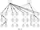
- FIG. 10 is a schematic diagram of a processing procedure performed when a target port is a downlink port of an aggregation device in a single-plane Clos architecture
- FIG. 11 is a schematic diagram of a processing procedure performed when a target port is an intra-group port in an architecture shown in FIG. 2 ;
- FIG. 12 is a schematic diagram of a processing procedure performed when a target port is an inter-group port in an architecture shown in FIG. 2 ;
- FIG. 13 is a schematic structural diagram of a network device according to an embodiment of this application.
- FIG. 14 is a schematic structural diagram of another network device according to an embodiment of this application.
- FIG. 15 is a schematic structural diagram of still another network device according to an embodiment of this application.
- Embodiments of this application provide a network congestion handling method and related apparatus, which can be applied to a system including a plurality of network devices.
- FIG. 1 is a schematic structural diagram of a network system according to an embodiment of this application.
- the network system uses a Clos architecture.
- the network system includes an access layer 11 , an aggregation layer 12 , and a core layer 13 .
- the access layer 11 includes a plurality of access devices T 1 to T 8
- the aggregation layer 12 includes a plurality of aggregation devices A 1 to A 7
- the core layer 13 includes a plurality of core devices C 1 to C 4 .
- Each access device is connected to one or more hosts Hx.
- the Clos architecture in FIG. 1 is a multi-plane architecture. Multi-plane means that there are a plurality of core device groups, and each aggregation device is connected to the core devices in the same core device group.
- FIG. 1 there are a core device group (C 1 , C 2 ) and a core device group (C 3 , C 4 ).
- the core device group (C 1 , C 2 ) includes the core devices C 1 and C 2
- the core device group (C 3 , C 4 ) includes the core devices C 3 and C 4 .
- Each core device group and the aggregation devices connected to the core device group form one forwarding plane.
- the core device group (C 1 , C 2 ) and the aggregation devices A 1 , A 3 , A 5 , and A 7 form one forwarding plane
- the core device group (C 3 , C 4 ) and the aggregation devices A 2 , A 4 , A 6 , and A 8 form one forwarding plane
- the access devices and the aggregation devices may further form different points of delivery (pod).
- Each pod includes a specific quantity of access devices and a specific quantity of aggregation devices, and an access device in a pod is connected to all aggregation devices in the same pod.
- the pod 1 includes the aggregation devices A 1 and A 2 , the access device T 1 in the pod 1 is connected to the aggregation devices A 1 and A 2 , and the access device T 2 is also connected to the aggregation devices A 1 and A 2 .
- Each core device at the core layer is connected to all pods.
- FIG. 1 shows a plurality of pods to describe a connection relationship between devices.
- pods are not drawn in subsequent accompanying drawings related to a Clos network.
- the multi-plane Clos architecture in FIG. 1 may be replaced with a single-plane Clos architecture, that is, each core device is connected to all aggregation devices.
- the access device in this application may be a switch, and the aggregation device and the core device may be switches or routers.
- FIG. 2 is a schematic structural diagram of another network system according to an embodiment of this application.
- the network architecture includes a plurality of switch groups (four switch groups are shown in FIG. 2 ).
- Each switch group may be referred to as a pod.
- Each switch group (pod) includes N switches.
- the number (identifier) of each switch uses a format of xy, where x indicates the pod to which the switch belongs, and y indicates the number of the switch in the pod to which the switch belongs.
- the pod 1 includes switches 11 , 12 , 13 , . . . , and 1 N; the pod 2 includes switches 21 , 22 , 23 , . . .
- a pod 3 includes switches 31 , 32 , 33 , . . . , and 3 N; and the pod 4 includes switches 41 , 42 , 43 , . . . , and 4 N. Every two of N switches in each switch group are directly connected. Each switch is directly connected to a corresponding switch in another pod to form N inter-group planes.
- the corresponding switch refers to a switch with the same number (identifier) in a different switch group.
- the switches 11 , 21 , 31 , and 41 are corresponding switches.
- the switches 11 , 21 , 31 , and 41 are interconnected to form an inter-group plane on the left of FIG.
- the direct connection means that there is no network device such as another switch or router between two switches, but there may be a device configured to provide a connection or a device configured to enhance a signal.
- Ports for connecting switches in different switch groups are referred to as inter-group ports, and ports for connecting switches in a same switch group are referred to as intra-group ports.
- Switches in one pod have the same configuration or specifications. Each pod forms one intra-group plane. Further, each switch shown in FIG. 2 is further connected to one or more hosts. FIG. 2 shows only hosts H 1 and H 2 corresponding to the switch 11 .
- this application provides a network congestion handling method as shown in FIG. 3 .
- the method is implemented by a first network device and a second network device in cooperation.
- the first network device may be any device in FIG. 1 or FIG. 2
- the second network device may be determined by the first network device, or may be preconfigured. The following describes the method with reference to FIG. 3 .
- step 301 the first network device determines a target port.
- the target port is an egress port that is in a congestion state or a pre-congestion state.
- the pre-congestion state is a state in which congestion is about to occur but has not yet occurred.
- the target port is an egress port of the first network device
- step 301 may include 301 - 1 and 301 - 2 .
- the first network device monitors egress ports of the first network device.
- the first network device may be any network device.
- the to-be-sent packet enters an egress port queue of an egress port.
- Each egress port corresponds to a plurality of (for example, eight) egress port queues. That the first network device monitors egress ports of the first network device may comprise monitoring each egress port of the first network device, or may be monitoring each egress port queue of the first network device.
- the first network device monitors whether a buffer usage of each egress port exceeds a first threshold, or the first network device monitors whether a length of each egress port queue exceeds a second threshold.
- the first threshold indicates an occupied proportion or a quantity of used bytes of a buffer of one egress port, and may also be referred to as a port buffer threshold.
- the second threshold indicates an occupied proportion or a quantity of used bytes in a buffer of one egress port queue, and may also be referred to as a queue buffer threshold.
- step 301 - 2 the first network device determines the target port based on a monitoring result.
- the first network device determines the egress port as the target port.
- the first threshold may be a pre-congestion threshold or a congestion threshold.
- the egress port is in the pre-congestion state.
- the egress port is in the congestion state.
- the first network device determines that an egress port corresponding to the egress port queue is the target port.
- the egress port queue may be referred to as a target egress port queue.
- the first network device allocates a buffer zone to each egress port queue.
- a maximum length of an egress port queue is the size of a buffer allocated to the egress port queue.
- the second threshold may be a length (a quantity of bytes) or a proportion.
- a maximum length of an egress port queue A is 2 MB, and the second threshold is 70%. If the amount of data stored in a buffer zone of the egress port queue A reaches or exceeds 1.4 MB, it may be determined that the egress port queue A is in a pre-congestion state or a congestion state (which is determined according to a setting).
- the first network device determines that an egress port corresponding to the egress port queue A is the target port.
- the first network device is not a network device to which the target port belongs, and step 301 includes: The first network device receives a notification A sent by a third network device.
- the third network device is the network device to which the target port belongs.
- the notification A includes information of the third network device and information of the target port.
- the first network device determines the target port based on the information of the target port in the notification A. Further, the notification A may further include an identifier of an egress port queue that is in the pre-congestion state or the congestion state in the target port.
- the first network device further stores congestion information.
- the congestion information includes the information of the target port and the information of the network device to which the target port belongs.
- the congestion information may further include a state of the target port, so that when a data flow is subsequently received, the data flow is processed based on the congestion information.
- the first network device sets an aging time for the congestion information, and deletes the congestion information when the aging time expires.
- the first network device sends a notification B to at least one second network device.
- the notification B includes the information of the network device to which the target port belongs and the information of the target port.
- the notification B may further include a type of the notification B, and the type is used to indicate that the target port identified in the notification B is a port that is in a pre-congestion state or a congestion state.
- the information of the target port in the notification B includes the state of the target port, and the state includes a pre-congestion state or a congestion state.
- the notification B further includes an identifier of an egress port queue that is in the congestion state or the pre-congestion state in the target port.
- the information of the network device to which the target port belongs and the information of the target port that are included in the notification B are collectively referred to as the congestion information.
- the first network device may send the notification B to the at least one second network device in a multicast mode, or may send the notification B to each of the at least one second network device in a unicast mode.
- the information of the network device to which the target port belongs includes an identifier of the network device, and the information of the target port includes an identifier of the target port or an identifier of a path on which the target port is located.
- the identifier of the path on which the target port is located may be an identifier of a network device on a forwarding path on which the target port is located.
- the information of the network device to which the target port belongs includes the identifier of the network device and a role of the network device, and the information of the target port includes the identifier of the target port and an attribute of the target port.
- the at least one second network device may be preconfigured, or may be determined by the first network device according to a preset rule.
- the at least one second network device includes one or more network devices capable of sending, through at least two forwarding paths, a data flow to a host corresponding to the target port.
- the at least one second network device includes one or more network devices that are capable of sending, through at least two forwarding paths, a data flow to a host corresponding to the target port and that have a smallest hop count to the network device to which the target port belongs.
- the host corresponding to the target port is a near-end host that can receive a data flow through the target port.
- the at least one second network device is determined based on the role of the network device to which the target port belongs, the attribute of the target port, and a role of the first network device.
- the attribute of the target port indicates a forwarding direction of a data flow in the target port
- the role of the network device indicates a location of the network device in the network system.
- the role of a network device may be an access device, an aggregation device, or a core device.
- An attribute of a port includes an uplink/downlink port.
- a port on the access device connected to the aggregation device and a port on the aggregation device connected to the core device are uplink ports.
- a port on the core device connected to the aggregation device and a port on the aggregation device connected to the access device are downlink ports.
- a near-end host with respect to a specific device is a host that when the device sends a data packet to the host, the data packet does not cross or go through a core device. For example, in FIG.
- near-end hosts corresponding to a port 4 of a core device C 2 are hosts connected to access devices T 7 and T 8 .
- near-end hosts corresponding to a port 3 of an aggregation device A 7 are hosts connected to access devices T 7 and T 8 .
- a near-end host corresponding to a port 3 of an access device T 7 is a host connected to the access device T 7 .
- near-end hosts corresponding to a port 1 of an aggregation device A 1 are hosts connected to access devices T 1 and T 2 .
- near-end hosts connected to a port 7 of a core device C 1 are hosts connected to access devices T 7 and T 8 .
- a near-end host corresponding to a port 1 of an access device T 7 is a host connected to the access device T 7 .
- a near-end host is a host connected to a switch that is directly connected to a target port.
- near-end hosts corresponding to a port 3 of a switch 3 N are hosts 34 connected to a switch 33 .
- near-end hosts corresponding to a port 2 of a switch 1 N are hosts connected to a switch 2 N.
- the first network device may further determine whether an idle egress port capable of forwarding a target data flow exists on the first network device. When no idle egress port is available, step 302 is performed. When an idle egress port is available, the first network device forwards the target data flow through the idle egress port.
- the target data flow is a data flow corresponding to a target address range.
- the target address range is an address range corresponding to the host corresponding to the target port, and the target address range is determined based on the information of the network device to which the target port belongs and the information of the target port.
- the target data flow includes a data flow sent to the host corresponding to the target port.
- the target data flow includes a data flow that is sent to the host corresponding to the target port and whose priority corresponds to the identifier of the egress port queue that is in the congestion state or the pre-congestion state.
- the target data flow may alternatively be an elephant flow in the data flow sent to the host corresponding to the target port, or an elephant flow in the data flow that is sent to the host corresponding to the target port and whose priority corresponds to the identifier of the egress port queue that is in the congestion state or the pre-congestion state.
- the elephant flow is a data flow whose traffic (in total bytes) in a unit time exceeds a specified threshold.
- a packet in a data flow carries a priority.
- a network device schedules data flows with a same priority to a same egress port queue. In this way, packets with different priorities enter different egress port queues on an egress port. Therefore, there is a correspondence between a packet priority and an identifier of an egress port queue.
- one network device may learn, based on a priority of a data flow received by the network device, of an identifier of an egress port queue that corresponds to the data flow and that is on another network device.
- the target port When the target port is a downlink port in the Clos architecture shown in FIG. 1 , that the target data flow corresponds to the target address range means that an address of the target data flow belongs to the target address range.
- the target port When the target port is an uplink port in the Clos architecture shown in FIG. 1 , that the target data flow corresponds to the target address range means that an address of the target data flow does not belong to the target address range.
- the target port is an intra-group port or an inter-group port in the architecture shown in FIG. 2 , that the target data flow corresponds to the target address range means that an address of the target data flow belongs to the target address range.
- step 303 the second network device receives the notification B.
- the second network device is any one of the at least one second network device.
- the second network device stores the information of the network device to which the target port belongs and the information of the target port that are carried in the notification B.
- the second network device may further store the state of the target port.
- the second network device sets a first table to store information of a port that is in the pre-congestion state or the congestion state, and each entry of the first table includes information about one target port and information of a network device to which the target port belongs.
- the second network device sets a second table, and each entry of the second table includes information about one target port, information of a network device to which the target port belongs, and a state of the target port.
- the second network device may set an aging time for information about each target port, and delete the information of the target port after the aging time expires.
- step 304 the second network device determines the target data flow.
- the second network device receives the notification B, the second network device is not the network device to which the target port belongs.
- the second network device determines the target address range based on the information of the network device to which the target port belongs and the information of the target port that are in the notification B, stores the target address range, and determines a subsequently received data flow whose destination address belongs to the target address range as the target data flow. For example, the second network device obtains a destination address of a received data flow. If the destination address belongs to the target address range, or the destination address belongs to the target address range and the priority of the data flow corresponds to the identifier of the target egress port queue, the second network device determines the data flow as the target data flow.
- the target address range is an address range corresponding to the host corresponding to the target port, and a first forwarding path (that is, an initial forwarding path before the notification B is received) of the target data flow includes the target port.
- the second network device determines whether an idle egress port capable of forwarding the target data flow exists on the second network device, obtains a result of the determination, and processes the target data flow based on the result of the determination.
- the idle egress port is another egress port that is on the second network device, is not in the congestion state or the pre-congestion state, and is different from a current egress port of the target data flow.
- a buffer usage of the idle egress port does not exceed the foregoing first threshold, or the length of no egress port queue in the idle egress port exceeds the foregoing second threshold.
- the target port is a downlink port 4 ; and when the second network device is an aggregation device A 1 , a target address range determined by the aggregation device A 1 is an address range corresponding to the hosts connected to the access devices T 7 and T 8 .
- the aggregation device A 1 receives a data flow whose destination address belongs to the target address range, the aggregation device A 1 determines whether an idle egress port exists in an uplink port of the aggregation device A 1 , and a forwarding path on which the idle egress port is located does not include the downlink port 4 of the core device C 2 .
- That the second network device processes the target data flow based on the result of the determining includes step 306 and step 307 .
- step 306 an idle egress port exists on the second network device, and the second network device sends the target data flow through the idle egress port.
- a forwarding path on which the idle egress port is located and that is determined by the second network device for the target data flow is referred to as a second forwarding path of the target data flow, and the second forwarding path does not include the target port.
- the second network device notifies the pre-congestion state or the congestion state of the target port to at least one third network device capable of sending a data flow to the host corresponding to the target port through the at least two forwarding paths.
- the second network device generates a notification C based on the information of the network device to which the target port belongs and the information of the target port, and sends the notification C to the third network device.
- the at least one third network device may be preconfigured on the second network device, or may be determined by the second network device based on the information of the network device to which the target port belongs and the information of the target port.
- the core device C 2 first determines whether another idle egress port capable of arriving at the host H 7 exists on the core device C 2 .
- the core device C 2 sends a multicast notification to a plurality of aggregation devices other than the aggregation device A 7 that is connected to the port 4 (step 302 ).
- the plurality of aggregation devices and the core device C 2 belong to a same forwarding plane.
- the core device 2 determines a target multicast group corresponding to the port 4 .
- the multicast notification may further include one or more of: a role of the core device C 2 , a port attribute (a downlink port) of the port 4 , and an identifier (Q 3 ) of the egress port queue 3 .
- the core device C 2 may further store congestion information of the port 4 .
- the multicast notification arrives at the aggregation devices A 1 , A 3 , and A 5 .
- the following uses the aggregation device A 1 as an example to describe a processing procedure of the aggregation device.
- the aggregation device A 1 receives the multicast notification sent by the core device C 2 (step 303 ). Optionally, the aggregation device A 1 obtains congestion information (“C 2 P 4 ”, “C 2 P 4 Q 3 ”, or “C 2 P 4 Q 3 downlink”) in the multicast notification, stores the congestion information, and sets an aging time. The aggregation device A 1 determines a target data flow (step 304 ).
- the core device C 2 determines address ranges of all hosts connected to the aggregation device A 7 connected to the P 4 .
- addresses may be allocated to a network device and a host based on the network architecture. For example, a number is allocated to each network device in FIG. 1 , and the number is an identifier of the network device. As shown in FIG. 5 , a number in each block representing a network device is a specific implementation of an identifier of a switch. For example, 10 may be a value of the C 2 . Each combination of an identifier of a network device and a downlink port identifier may uniquely identify a lower-layer device.
- an identifier of a network device included in the multicast notification received by the aggregation device A 1 is 10, and a port identifier is 11, so that the aggregation device A 1 determines, based on the multicast notification, that a host address range determined by the multicast notification is least significant five bits to least significant 10 bits, that is, 110000 or 111111, and that a determined priority is a priority corresponding to the Q 3 , for example, 3.
- the aggregation device A 1 determines, as the target data stream, a received data flow whose destination address falls within the host address range and whose priority is 3.
- the aggregation device A 1 determines, through table lookup, the address ranges of the hosts connected to the port P 4 of the core device C 2 .
- each network device stores three tables.
- a first table stores a correspondence between a core device, a port of the core device, and an aggregation device.
- a second table stores a connection relationship between an aggregation device, a port of the aggregation device, and an access device.
- a third table stores a connection relationship between an access device and a host address.
- the aggregation device A 1 After determining the target data flow (assuming that the target data flow is the data flow 1 ), the aggregation device A 1 determines whether an idle uplink egress port exists on the aggregation device A 1 (because the target port P 4 is the downlink port of the core device, and the downlink port of the core device corresponds to an uplink port of an aggregation device, the aggregation device A 1 needs to determine whether an idle uplink port exists) (step 305 ). When an idle uplink egress port exists or is available, the aggregation device A 1 uses the idle uplink egress port as an egress port of the target data flow, and forwards the target data flow through the idle uplink egress port (step 306 ). When no idle uplink egress port exists, the aggregation device A 1 continues to forward the target data flow through an initial forwarding path corresponding to the target data flow (step 307 ).
- the aggregation device A 1 further propagates the congestion information to the access device.
- the aggregation device A 1 further generates another notification, and sends the other notification to the access devices T 1 and T 2 (step 302 ).
- the other notification includes the congestion information.
- the access devices T 1 and T 2 perform corresponding processing.
- the following uses the access device T 2 as an example to describe a processing procedure of the access device.
- the access device T 2 After the access device T 2 receives the other notification (step 303 ), similar to the aggregation device A 1 , the access device T 2 obtains the congestion information in the other notification, stores the congestion information, and sets an aging time. The access device T 2 determines the target address range based on the congestion information, determines the target data flow based on the target address range (step 304 ), and determines whether an idle egress port capable of forwarding the target data flow exists on the access device T 2 (step 305 ). If an idle egress port exists, the access device T 2 forwards the target data flow through the idle egress port (step 306 ).
- the core device may send the congestion information to the aggregation device, and the aggregation device may send the congestion information to the access device.
- Each network device that receives the congestion information performs an operation of handling network congestion, so that network congestion can be avoided, and bandwidth utilization of the entire Clos system can be improved.
- FIG. 6 is a schematic diagram of a processing procedure performed when a target port is a downlink port of an aggregation device in a multi-plane Clos architecture shown in FIG. 1 .
- a thin solid line represents a link on which the target port is located, and a thick solid line represents a forwarding path of a notification.
- a host H 2 sends a data flow 1 to a host H 7 ; and when the data flow 1 enters a queue 3 of an egress port 3 on an aggregation device A 7 , the aggregation device A 7 detects that a length of the queue 3 of the egress port 3 exceeds a second threshold and determines that the queue 3 is in a pre-congestion state.
- the egress port 3 is the target port. No idle downlink port exists on the aggregation device A 7 .
- the aggregation device A 7 sends the notification to a plurality of second network devices (step 302 ).
- the plurality of second network devices are determined based on a port attribute (a downlink port) of the egress port 3 and an attribute (an aggregation device) of the aggregation device A 7 , and include all access devices except an access device T 7 connected to the egress port 3 .
- the notification includes an identifier (A 7 ) of the aggregation device A 7 and an identifier (P 3 ) of the egress port 3 .
- the notification may further include one or more of: a role (an aggregation device) of the aggregation device A 7 , the attribute (a downlink port) of the egress port 3 , and an identifier (Q 3 ) of the queue 3 .
- the notification may be sent in a unicast or multicast mode.
- a notification sent by the aggregation device A 7 to an access device T 8 may directly arrive at the access device T 8 , and a notification sent to access devices T 1 to T 6 first arrives at the core devices C 1 and C 2 that belong to a same forwarding plane as the aggregation device A 7 .
- the core devices C 1 and C 2 cannot send a data flow to a host corresponding to the egress port 3 of the aggregation device A 7 through at least two forwarding paths, the core devices C 1 and C 2 are not destinations of the notification. After receiving the notification, the core devices C 1 and C 2 forward the notification to ports other than the port that received the notification ( FIG. 6 shows only a forwarding path of the core device C 2 ).
- the notification After being forwarded by the core device C 1 or C 2 , the notification arrives at aggregation devices A 1 , A 3 , and A 5 that belong to a same forwarding plane as the aggregation device A 7 . Because the aggregation devices A 1 , A 3 , and A 5 cannot send a data flow to the host corresponding to the egress port 3 of the aggregation device A 7 through at least two forwarding paths, the aggregation devices A 1 , A 3 , and A 5 are not destinations of the notification, and the aggregation devices A 1 , A 3 , and A 5 still need to forward the received notification.
- the aggregation device A 1 is used as an example. After receiving the notification, the aggregation device A 1 replicates and forwards the notification to downlink ports, that is, sends the notification to connected access devices T 1 and T 2 .
- a destination of the notification sent by the aggregation device A 7 is an access device other than the access device T 7 . Therefore, after receiving the notification, both the core device and the aggregation device only forward the notification. After receiving the notification, any one of the access devices T 1 to T 6 and T 8 performs step 304 to step 307 with reference to the manners described in the foregoing embodiments.
- the aggregation device in the Clos system may send congestion information to all other access devices except an access device connected to the egress port.
- Each access device that receives the congestion information performs an operation of handling network congestion. Therefore, the foregoing process can alleviate network congestion and improve bandwidth utilization of the entire Clos system.
- FIG. 7 is a schematic diagram of a processing procedure performed when a target port is a downlink port of an access device in a multi-plane Clos architecture.
- a thin solid line represents a link on which the target port is located
- a thick solid line represents a forwarding path of a notification.
- a host H 2 sends a data flow 1 to a host H 7 ; and when the data flow 1 enters a queue 3 of an egress port 3 on an access device T 7 , the access device T 7 detects that a length of the queue 3 of the egress port 3 exceeds a second threshold and determines that the queue 3 is in a pre-congestion state.
- the egress port 3 is determined as the target port.
- no other downlink port that can send a data flow to arrive at the host H 7 exists on the access device T 7 .
- the access device T 7 generates a notification, where the notification includes an identifier (T 7 ) of the access device T 7 and an identifier (P 3 ) of the egress port 3 .
- the notification may include one or more of a role (an access device) of the access device T 7 , an attribute (a downlink port) of the egress port 3 , and an identifier (Q 3 ) of the queue 3 .
- the access device T 7 sends the notification to a plurality of second network devices.
- the plurality of second network devices include several or all other access devices except the access device T 7 .
- the access device T 7 is directly connected to the host H 7 , and the access device T 7 learns of an address of the host H 7 . Therefore, the notification may further include the address of the host H 7 . In this way, another access device that receives the notification may directly determine the target data flow based on the address of the host H 7 .
- the notification may be sent in a unicast or multicast mode.
- an aggregation device or a core device forwards the notification based on a destination address of the notification.
- each access device performs an operation similar to that performed by the access device T 2 in FIG. 4 .
- all target ports are downlink ports.
- the target port may alternatively be an uplink port.
- FIG. 8 is a schematic diagram of a processing procedure performed when a target port is an uplink port of an aggregation device in a multi-plane Clos architecture.
- a thin solid line represents a link on which the target port is located, and a thick solid line represents a forwarding path of a notification.
- a data flow 1 sent from a host H 2 to a host H 7 is still used as an example.
- an aggregation device A 1 detects that a length of an egress port queue 3 (Q 3 ) of a port 1 (P 1 ) on which the data flow 1 is located exceeds a second threshold, and determines that the egress port queue 3 is in a pre-congestion state.
- the egress port 1 is the target port.
- the aggregation device A 1 determines whether another idle egress port (an uplink port) capable of arriving at the host H 7 exists on the aggregation device A 1 . If another idle egress port capable of arriving at the host H 7 exists, the aggregation device A 1 switches the data flow 1 to the idle egress port, and sends the data flow 1 through the idle egress port. When no other idle egress port capable of arriving at the host H 7 exists, the aggregation device A 1 sends, in a multicast or unicast mode, a notification to a plurality of access devices connected to the aggregation device A 1 (step 302 ).
- the notification includes an identifier (A 1 ) of the aggregation device A 1 and an identifier (P 1 ) of the port 1 .
- the notification may further include a role (an aggregation device) of the aggregation device A 1 , an attribute (an uplink port) of the port 1 , and an identifier (Q 3 ) of the egress port queue 3 .
- aggregation devices A 3 , A 5 , and A 7 can send, through at least two forwarding paths, a data flow to a host corresponding to the target port.
- the aggregation device A 1 sends the notification only to access devices T 1 and T 2 , but does not send the notification to the aggregation devices A 3 , A 5 , A 7 , or another access device.
- the notification arrives at the access devices T 1 and T 2 .
- the following description uses the access device T 2 as an example to describe a processing procedure of the access device.
- the access device T 2 After receiving the notification (step 303 ), the access device T 2 obtains congestion information in the notification, stores the congestion information, and sets an aging time.
- the access device T 2 determines a target address range corresponding to the aggregation device A 1 , for example, addresses of hosts corresponding to all access devices connected to the aggregation device A 1 , and determines, as a target data flow, a data flow whose destination address does not belong to the target address range or whose destination address does not belong to the target address range and whose priority corresponds to the Q 3 (step 304 ).
- an uplink port of the aggregation device A 1 is faulty, and data flows sent between the hosts of the aggregation device A 1 do not pass through the uplink port of the aggregation device A 1 . Therefore, the access device T 2 selects a data flow sent to a host beyond a management range of the aggregation device A 1 as the target data flow. After determining the target data flow, the access device T 2 determines whether an idle egress port (an uplink port) corresponding to the congestion information exists on the access device T 2 (step 305 ). If an idle egress port exists, the access device T 2 forwards the target data flow through the idle egress port (step 306 ).
- the access device T 2 sends the target data flow through an initial forwarding path of the target data flow (step 307 ). Further, the access device T 2 determines a source host of the target data flow, and sends a backpressure message to the source host. The backpressure message is used to notify the source host to perform an operation of handling network congestion.
- the operation of handling network congestion may be reducing the rate of sending data to the access device T 2 or reducing the rate of sending the target data flow to the access device T 2 .
- the access device determines a data flow sent to the uplink port as the target data flow, and determines whether an idle egress port (an uplink port) capable of forwarding the target data flow exists on the access device. If an idle egress port exists, the target data flow is sent through the idle egress port. If no idle egress port exists, a source host of the target data flow is determined, and the back pressure message is sent to the source host. The backpressure message is used to indicate the source host to perform the operation of handling network congestion. It can be learned that when the target port is the uplink port of the access device, the access device does not need to send a notification.
- each core device is connected to all aggregation devices.
- FIG. 9 is a schematic diagram of a processing procedure performed when a target port is a downlink port of a core device in a single-plane Clos architecture.
- a thin solid line represents a link on which the target port is located
- a thick solid line represents a forwarding path of a notification.
- a data flow (denoted as a data flow 1 ) sent from a host H 2 to a host H 7 arrives at a core device C 1 through an access device T 2 and an aggregation device A 1 .
- the core device C 1 forwards the data flow 1 to an aggregation device A 7 through an egress port queue 3 (Q 3 ) of a port 7 (P 7 ).
- a core device C 2 detects that a length of the egress port queue 3 exceeds a second threshold and determines that the egress port queue 3 is in a pre-congestion state. In this case, the port 7 is determined as the target port (step 301 ). Because no idle egress port (that is, an idle downlink egress port) having a same attribute as the port 7 exists on the core device C 1 , the core device C 1 sends the notification to other aggregation devices except the aggregation device A 7 . For congestion information included in the notification, refer to the description related to FIG. 4 .
- the aggregation device or devices After receiving the notification, the aggregation device or devices (for example, A 1 ) determine a target address range (that is, the addresses of the hosts connected to the access devices T 7 and T 8 ) based on the notification, determines a target data flow based on the target address range after receiving the data flow, and then determines whether an idle egress port (an uplink port) capable of forwarding the target data flow exists.
- a target address range that is, the addresses of the hosts connected to the access devices T 7 and T 8
- an idle egress port exists
- the target data flow is switched to the idle egress port; and when no idle port exists, the data flow is forwarded through a current egress port of the target data flow, a notification is regenerated based on the congestion information, and the notification is sent to
- the access device After receiving the notification, the access device (for example, T 2 ) determines a target data flow based on the congestion information. In addition, when an idle egress port capable of forwarding the target data flow exists, the access device switches the target data flow to the idle egress port (the uplink port); and when no idle egress port exists, the access device sends the backpressure message to a source host of the target data flow. The backpressure message is used to indicate to the source host to perform an operation of handling network congestion.
- FIG. 10 is a schematic diagram of a processing procedure performed when a target port is a downlink port of an aggregation device in a single-plane Clos architecture.
- a thin solid line represents a link on which the target port is located
- a thick solid line represents a forwarding path of a notification.
- a data flow (denoted as a data flow 1 ) sent from a host H 2 to a host H 7 arrives at an aggregation device A 7 through an access device T 2 , an aggregation device A 1 , and a core device C 1 .
- the aggregation device A 7 forwards the data flow 1 to an access device T 7 through an egress port queue 3 (Q 3 ) of a port 1 (P 7 ).
- the aggregation device A 7 detects that a length of the egress port queue 3 exceeds a second threshold and determines that the egress port queue 3 is in a pre-congestion state. In this case, the port 1 is determined as the target port (step 301 ).
- the aggregation device A 7 sends the notification to all core devices and another access device (for example, the access device T 8 ) connected to the aggregation device.
- the notification includes congestion information (for the congestion information, refer to the foregoing embodiments).
- the core devices C 1 and C 2 can also send, through at least two forwarding paths, a data flow to a host corresponding to the port 1 of the aggregation device A 7 , and the core devices C 1 and C 2 have only one hop to the aggregation device A 7 .
- the aggregation device sends the notification to the core devices C 1 and C 2 and the access device T 8 .
- the core device After receiving the notification, the core device (for example, C 1 ) determines a target data flow based on the congestion information. If an idle downlink egress port capable of forwarding the target data flow exists on the core device, the core device sends the target data flow through the idle downlink egress port. If no idle downlink egress port capable of forwarding the target data flow exists on the core device, the notification is sent to an aggregation device other than the aggregation device A 7 , and the notification includes the congestion information.
- any aggregation device After receiving the notification sent by the core device, any aggregation device performs an operation that is the same as that performed by the aggregation device A 1 in FIG. 9 .
- any access device in FIG. 10 After receiving the notification, any access device in FIG. 10 performs an operation that is the same as that performed by the access device T 2 in FIG. 9 .
- a processing procedure performed when the target port is a downlink port of an access device in the single-plane Clos architecture is similar to a processing procedure performed when the target port is a downlink port of an access device in a multi-plane architecture.
- a processing method used when the target port is an uplink port in the single-plane Clos architecture is similar to a processing method used when the target port is an uplink port in the multi-plane Clos architecture.
- an identifier of each switch may be a number of the switch.
- the number of the switch may be xy, where x represents the number of the pod in which the switch is located, and y represents the number of the switch in the pod in which the switch is located.
- a switch 11 represents a switch whose number is 1 in the pod 1 . In this way, a first switch may learn of the role of a second switch based on the number of the second switch, and may also learn of an attribute of a port of the second switch.
- FIG. 11 is a schematic diagram of a processing procedure performed when a target port is an intra-group port in an architecture shown in FIG. 2 . It is assumed that in a process of sending a data flow 1 to a switch 33 , a switch 3 N detects that a length of an egress port queue 3 of a port 3 exceeds a second threshold and determines that the egress port queue 3 is in a pre-congestion state. In this case, the port 3 is determined as the target port (step 301 ). The switch 3 N sends a notification to a plurality of second network devices, and the notification includes an identifier of the switch 3 N and an identifier of the port 3 (step 302 ).
- the identifier of the switch 3 N may be obtained by parsing the identifier of the port 3 .
- the identifier of the switch 3 N and the identifier of the port 3 N may use only one field.
- the notification may further include an identifier of the egress port queue 3 .
- the notification may further include an attribute of the port 3 and a role (an inter-group switch) of the switch 3 N.
- the plurality of second network devices include inter-group switches connected to the switch 3 N, that is, switches 1 N, 2 N, and 4 N. There is only one hop between the switch 3 N and each of the inter-group switches.
- the switch 3 N sends the notification to the switches 1 N, 2 N, and 4 N in a multicast or unicast mode.
- the following uses the switch 1 N as an example to describe a process in which the switches 1 N, 2 N, and 4 N process the notification.
- the switch 1 N After receiving the notification (step 303 ), the switch 1 N obtains congestion information in the notification, stores the congestion information, and sets an aging time. The switch 1 N determines a target data flow based on the congestion information (step 304 ). The target data flow is a data flow sent to a host connected to the switch 3 N, or the target data flow is a data flow that is sent to a host connected to the switch 3 N and whose priority corresponds to the egress port queue 3 . The switch 1 N determines whether an idle egress port capable of sending the target data flow exists on the switch 1 N, that is, an idle inter-group port (step 305 ). If an idle egress port exists, the switch 1 N forwards the target data flow through the idle egress port (step 306 ).
- the switch 1 N sends the target data flow through an initial forwarding path of the target data flow (step 307 ). In addition, the switch 1 N sends the notification to another switch in a same switch group based on the congestion information. Switches 11 , 12 , and 13 receive the notification, and perform processing similar to that of an access device in a Clos architecture.
- an address may be allocated to a host based on a network architecture.
- an address of each host may be determined based on the number of a switch connected to the host. For example, an address of a host connected to the switch 1 N is 1N.XXX.XXX.
- the target data flow is a data flow whose destination address is 33.XXX.XXX and whose priority corresponds to the Q 3 .
- a processing procedure of the switch is similar to a processing procedure performed when the target port is the intra-group port.
- FIG. 12 is a schematic diagram of a processing procedure performed when a target port is an inter-group port in an architecture shown in FIG. 2 . It is assumed that in a process of sending a data flow 1 to a switch 2 N, a switch 1 N detects that a length of an egress port queue 3 of a port 2 of the switch 1 N exceeds a second threshold, that is, the egress port queue 3 is in a pre-congestion state. The switch 1 N determines the port 2 as the target port (step 301 ). A host corresponding to the target port is a host connected to the switch 2 N. The switch 1 N sends a notification to a plurality of second network devices (step 302 ).
- the plurality of second network devices include intra-group switches connected to the switch 1 N, that is, switches 11 , 12 , 13 , and the like.
- the notification includes an identifier ( 1 N) of the switch 1 N, and an identifier (P 2 ) of the port 2 .
- the notification may further include an identifier (Q 3 ) of the egress port queue 3 .
- the notification may further include an attribute of the port 2 and a role (an intra-group switch) of the switch 1 N.
- the switch 1 N sends the notification to the switches 11 , 12 , 13 , and the like in a multicast or unicast mode. Switches 11 , 12 , 13 , and the like receive the notification, and perform processing similar to that of an access device in a Clos architecture.
- a notification can be published to another network device in a network, and a network device that receives the notification selects an idle egress port for a target data flow or continues to propagate the congested state of the egress port or the egress port queue in the network, so that all network devices in the entire network can perform a network congestion handling operation, to alleviate network congestion in a plurality of network architectures.
- the network device in this application may forward the target data flow through the idle egress port, to implement end-to-end load balancing in the entire network, and improve network resource utilization.
- the target data flow in this application is based on the egress port queue, only the forwarding path of a data flow causing congestion is adjusted and the normal data flow is not affected, to further improve data flow forwarding efficiency.
- an embodiment of this application provides a network device 1300 .
- the network device 1300 may be any network device in FIG. 1 or FIG. 2 .
- the network device 1300 includes a determining unit 1310 and a sending unit 1320 .
- the network device 1300 further includes a receiving unit 1330 and a storage unit 1340 .
- the network device 1300 is configured to implement a function of the first network device in FIG. 3 .
- the determining unit 1310 is configured to determine a target port, where the target port is an egress port that is in a pre-congestion state or a congestion state.
- the sending unit 1320 is configured to send a first notification to at least one second network device.
- the at least one second network device includes one or more network devices capable of sending, through at least two forwarding paths, a data flow to a host corresponding to the target port, and the first notification includes information of a network device to which the target port belongs and information of the target port.
- the network device to which the target port belongs is the first network.
- the determining unit is configured to: monitor egress ports of the first network device; and when a buffer usage of one of the egress ports of the first network device exceeds a port buffer threshold, determine that the egress port is the target port.
- the network device to which the target port belongs is the first network.
- the determining unit is configured to: monitor egress port queues of the first network device; and when a length of one of the egress ports exceeds a queue buffer threshold, determine that an egress port corresponding to the egress port queue is the target port.
- the network device to which the target port belongs is a third network device.
- the receiving unit 1330 is configured to receive a second notification sent by the third network device, and the second notification includes information of the third network device and the information of the target port.
- the determining unit determines the target port based on the second notification.
- the information of the network device to which the target port belongs includes an identifier of the network device to which the target port belongs, and the information of the target port includes an identifier of the target port or an identifier of a forwarding path on which the target port is located.
- the information of the network device to which the target port belongs further includes a role of the network device to which the target port belongs, and the role indicates the location of the network device to which the target port belongs.
- the information of the target port further includes an attribute of the target port, and the attribute indicates the direction in which the target port sends a data flow.
- the determining unit is further configured to determine whether no idle egress port capable of forwarding a target data flow corresponding to the target port exists on the network device.
- the target data flow is a data flow corresponding to a target address range.
- the target address range is an address range corresponding to the host corresponding to the target port, and the target address range is determined based on the information of the network device to which the target port belongs and the information of the target port.
- the information of the target port may further include an identifier of a target egress port queue.
- the target egress port queue is an egress port queue that is in the congestion state or the pre-congestion state in the target port.
- the target data flow is a data flow that corresponds to the target address range and whose priority corresponds to an identifier of the egress port queue.
- the storage unit 1340 is configured to store the information of the network device to which the target port belongs and the information of the target port.
- the storage unit 1340 is further configured to store a state of the target port.
- the network device 1400 may be any network device in FIG. 1 or FIG. 2 .
- the network device 1400 includes a receiving unit 1410 , a first determining unit 1420 , a second determining unit 1430 , and a processing unit 1440 .
- the network device 1400 further includes a storage unit 1450 .
- the network device 1400 is configured to implement a function of the second network device in FIG. 3 .
- the receiving unit 1410 is configured to receive a first notification from a first network device.
- the first notification includes information of a network device to which a target port belongs and information of the target port.
- the target port is a port that is in a pre-congestion state or a congestion state.
- the second network device is a network device capable of sending, through at least two forwarding paths, a data flow to a host corresponding to the target port.
- the first determining unit 1420 is configured to determine a target data flow, where a first forwarding path of the target data flow includes the target port.
- the second determining unit 1430 is configured to determine whether an idle egress port capable of forwarding the target data flow exists on the second network device, and to obtain a result of the determination.
- the processing unit 1440 is configured to process the target data flow based on the result of the determination.
- the processing unit 1430 sends the target data flow through the idle egress port.
- a second forwarding path on which the idle egress port is located does not include the target port.
- the processing unit 1430 forwards the target data flow through the first forwarding path.
- the processing unit 1440 is further configured to: generate a second notification, where the second notification includes the information of the network device to which the target port belongs and the information of the target port; and send the second notification to at least one third network device, where the at least one third network device is capable of sending, through at least two forwarding paths, a data flow to a host corresponding to the target port.
- the processing unit 1440 is further configured to send a backpressure message to a source host of the target data flow.
- the backpressure message is used to enable the source host to perform an operation of handling network congestion.
- the first determining unit 1420 is configured to: determine a target address range based on the information of the network device to which the target port belongs and the information of the target port, where the target address range is an address range corresponding to the host corresponding to the target port; and determine a data flow whose destination address belongs to the target address range as the target data flow.
- the first notification further includes an identifier of a target egress port queue
- the target egress port queue is an egress port queue that is in the pre-congestion state or the congestion state in the target port.
- the first determining unit 1420 is further configured to determine, as the target data flow, a data flow whose destination address belongs to the target address range and whose priority corresponds to an identifier of the egress port queue.
- the storage unit 1450 is configured to store the information of the network device to which the target port belongs and the information of the target port.
- the storage unit 1450 is further configured to store a state of the target port.
- the network devices in FIG. 13 and FIG. 14 cooperate with each other, so that the method shown in FIG. 3 can be implemented, to alleviate network congestion and implement load balancing of an entire network.
- the network devices in FIG. 13 and FIG. 14 may be implemented by a network device 1500 shown in FIG. 15 .
- the network device 1500 may include a processor 1510 , a memory 1520 , and a bus system 1530 .
- the processor 1510 is connected to the memory 1520 through the bus system 1530 .
- the memory 1520 is configured to store program code
- the processor 1510 is configured to execute the program code stored in the memory 1520 .
- the processor 1510 may invoke the program code stored in the memory 1520 , to perform the network congestion handling method in the embodiments of this application.
- the processor 1510 may be a central processing unit (CPU).
- the processor 1510 may alternatively be another general purpose processor, a digital signal processor (DSP), an application-specific integrated circuit (ASIC), a field-programmable gate array (FPGA) or another programmable logic device, a discrete gate or transistor logic device, a discrete hardware component, or the like.
- the general purpose processor may be a microprocessor, or the processor may be any conventional processor or the like.
- the processor 1510 may include one or more processing cores.
- the memory 1520 may include a read-only memory (ROM) device or a random access memory (RAM) device. Any other suitable type of storage device may alternatively be used as the memory 1520 .
- the memory 1520 may include data 1522 accessed by the processor 1510 through the bus system 1530 .
- the memory 1520 may further include an operating system 1523 to support operation of the network device 1500 .
- the bus system 1530 may further include a power bus, a control bus, a status signal bus, and the like, in addition to a data bus. However, for clear description, various types of buses in the figure are marked as the bus system 1530 .
- the network device 1500 may further include one or more output devices, for example, a communications interface 1540 .
- the network device 1500 may communicate with another device through the communications interface 1540 .
- the communications interface 1540 may be connected to the processor 1510 through the bus system 1530 .
- the technical solutions of this application may be embodied in the form of a hardware product or a software product.
- the hardware product may be a dedicated chip.
- the software product may be stored in a non-volatile storage medium (which may be a CD-ROM, a USB flash drive, a removable hard disk, or the like), and includes instructions for instructing a computer device (which may be a personal computer, a server, a network device, or the like) to perform the methods described in the embodiments of this application.
Landscapes
- Engineering & Computer Science (AREA)
- Computer Networks & Wireless Communication (AREA)
- Signal Processing (AREA)
- Environmental & Geological Engineering (AREA)
- Data Exchanges In Wide-Area Networks (AREA)
Abstract
Description
Claims (19)
Applications Claiming Priority (5)
| Application Number | Priority Date | Filing Date | Title |
|---|---|---|---|
| CN201910673706 | 2019-07-24 | ||
| CN201910673706.7 | 2019-07-24 | ||
| CN201910913827.4A CN112311685B (en) | 2019-07-24 | 2019-09-25 | A method for processing network congestion and related device |
| CN201910913827.4 | 2019-09-25 | ||
| PCT/CN2020/099204 WO2021012902A1 (en) | 2019-07-24 | 2020-06-30 | Method for processing network congestion, and related apparatus |
Related Parent Applications (1)
| Application Number | Title | Priority Date | Filing Date |
|---|---|---|---|
| PCT/CN2020/099204 Continuation WO2021012902A1 (en) | 2019-07-24 | 2020-06-30 | Method for processing network congestion, and related apparatus |
Publications (2)
| Publication Number | Publication Date |
|---|---|
| US20220124036A1 US20220124036A1 (en) | 2022-04-21 |
| US12010023B2 true US12010023B2 (en) | 2024-06-11 |
Family
ID=74193168
Family Applications (1)
| Application Number | Title | Priority Date | Filing Date |
|---|---|---|---|
| US17/563,167 Active 2040-07-08 US12010023B2 (en) | 2019-07-24 | 2021-12-28 | Network congestion handling method and related apparatus |
Country Status (3)
| Country | Link |
|---|---|
| US (1) | US12010023B2 (en) |
| EP (1) | EP3972209A4 (en) |
| WO (1) | WO2021012902A1 (en) |
Families Citing this family (5)
| Publication number | Priority date | Publication date | Assignee | Title |
|---|---|---|---|---|
| CN116599885B (en) * | 2022-11-23 | 2025-09-30 | 同济大学 | A software-defined network routing method based on deep reinforcement learning |
| CN115883465B (en) * | 2022-12-01 | 2024-04-19 | 迈普通信技术股份有限公司 | Flow control method, device, server, system and storage medium |
| US12556494B2 (en) | 2023-02-27 | 2026-02-17 | Mellanox Technologies, Ltd. | Managing multiplane networks |
| US12568044B2 (en) | 2023-03-13 | 2026-03-03 | Mellanox Technologies, Ltd. | Inter-plane access |
| US12580850B2 (en) * | 2023-05-22 | 2026-03-17 | Mellanox Technologies, Ltd. | Dual software interfaces for multiplane devices to separate network management and communication traffic |
Citations (12)
| Publication number | Priority date | Publication date | Assignee | Title |
|---|---|---|---|---|
| US20070223372A1 (en) * | 2006-03-23 | 2007-09-27 | Lucent Technologies Inc. | Method and apparatus for preventing congestion in load-balancing networks |
| US7675857B1 (en) | 2006-05-03 | 2010-03-09 | Google Inc. | Method and apparatus to avoid network congestion |
| US20120092988A1 (en) * | 2009-06-23 | 2012-04-19 | Huawei Technologies Co., Ltd. | Method, apparatus, and system for judging path congestion |
| US20120233349A1 (en) * | 2011-03-09 | 2012-09-13 | Juniper Networks, Inc. | Methods and apparatus for path selection within a network based on flow duration |
| CN103907323A (en) | 2012-10-30 | 2014-07-02 | 华为技术有限公司 | Method for alleviating network congestion, core network equipment and access network equipment |
| CN104836743A (en) | 2015-05-25 | 2015-08-12 | 杭州华三通信技术有限公司 | Congestion control method and device |
| EP2950489A1 (en) | 2014-05-27 | 2015-12-02 | Huawei Technologies Co., Ltd. | Method and device for generating cnm |
| US20170048144A1 (en) | 2015-08-13 | 2017-02-16 | Futurewei Technologies, Inc. | Congestion Avoidance Traffic Steering (CATS) in Datacenter Networks |
| US10015096B1 (en) | 2016-06-20 | 2018-07-03 | Amazon Technologies, Inc. | Congestion avoidance in multipath routed flows |
| CN109981471A (en) | 2017-12-27 | 2019-07-05 | 华为技术有限公司 | A kind of method, apparatus and system for alleviating congestion |
| US20200044976A1 (en) * | 2018-07-31 | 2020-02-06 | Barefoot Networks, Inc. | Flow Control Visibility |
| US10812391B1 (en) * | 2017-01-27 | 2020-10-20 | Marvell Israel (M.I.S.L) Ltd. | Methods and apparatus for load balancing in a network |
-
2020
- 2020-06-30 WO PCT/CN2020/099204 patent/WO2021012902A1/en not_active Ceased
- 2020-06-30 EP EP20843498.5A patent/EP3972209A4/en active Pending
-
2021
- 2021-12-28 US US17/563,167 patent/US12010023B2/en active Active
Patent Citations (12)
| Publication number | Priority date | Publication date | Assignee | Title |
|---|---|---|---|---|
| US20070223372A1 (en) * | 2006-03-23 | 2007-09-27 | Lucent Technologies Inc. | Method and apparatus for preventing congestion in load-balancing networks |
| US7675857B1 (en) | 2006-05-03 | 2010-03-09 | Google Inc. | Method and apparatus to avoid network congestion |
| US20120092988A1 (en) * | 2009-06-23 | 2012-04-19 | Huawei Technologies Co., Ltd. | Method, apparatus, and system for judging path congestion |
| US20120233349A1 (en) * | 2011-03-09 | 2012-09-13 | Juniper Networks, Inc. | Methods and apparatus for path selection within a network based on flow duration |
| CN103907323A (en) | 2012-10-30 | 2014-07-02 | 华为技术有限公司 | Method for alleviating network congestion, core network equipment and access network equipment |
| EP2950489A1 (en) | 2014-05-27 | 2015-12-02 | Huawei Technologies Co., Ltd. | Method and device for generating cnm |
| CN104836743A (en) | 2015-05-25 | 2015-08-12 | 杭州华三通信技术有限公司 | Congestion control method and device |
| US20170048144A1 (en) | 2015-08-13 | 2017-02-16 | Futurewei Technologies, Inc. | Congestion Avoidance Traffic Steering (CATS) in Datacenter Networks |
| US10015096B1 (en) | 2016-06-20 | 2018-07-03 | Amazon Technologies, Inc. | Congestion avoidance in multipath routed flows |
| US10812391B1 (en) * | 2017-01-27 | 2020-10-20 | Marvell Israel (M.I.S.L) Ltd. | Methods and apparatus for load balancing in a network |
| CN109981471A (en) | 2017-12-27 | 2019-07-05 | 华为技术有限公司 | A kind of method, apparatus and system for alleviating congestion |
| US20200044976A1 (en) * | 2018-07-31 | 2020-02-06 | Barefoot Networks, Inc. | Flow Control Visibility |
Non-Patent Citations (3)
| Title |
|---|
| K. Ramakrishnan et al., "The Addition of Explicit Congestion Notification (ECN) to IP", Request for Comments: 3168, Network Working Group,Sep. 2001,total 63 pages. |
| M. Mahalingam et al., "Virtual extensible Local Area Network (VXLAN): A Framework for Overlaying Virtualized Layer 2 Networks over Layer 3 Networks",Request for Comments: 7348,Independent Submission,Aug. 2014,total 22 pages. |
| Mohammad Al-Fares et al.,"A scalable, commodity data center network architecture", ACM SIGCOMM Computer Communication Review,vol. 38,Issue 4,Oct. 2008,total 12 pages. |
Also Published As
| Publication number | Publication date |
|---|---|
| WO2021012902A1 (en) | 2021-01-28 |
| EP3972209A4 (en) | 2022-07-06 |
| US20220124036A1 (en) | 2022-04-21 |
| EP3972209A1 (en) | 2022-03-23 |
Similar Documents
| Publication | Publication Date | Title |
|---|---|---|
| US12010023B2 (en) | Network congestion handling method and related apparatus | |
| CN109981471B (en) | Method, equipment and system for relieving congestion | |
| US7733770B2 (en) | Congestion control in a network | |
| US9467522B2 (en) | Ingress based headroom buffering for switch architectures | |
| CN100466629C (en) | Network equipment and message transferring method based on multiple-core processor | |
| CN112311685B (en) | A method for processing network congestion and related device | |
| US20170048144A1 (en) | Congestion Avoidance Traffic Steering (CATS) in Datacenter Networks | |
| US9985910B2 (en) | Adaptive flow prioritization | |
| US10728156B2 (en) | Scalable, low latency, deep buffered switch architecture | |
| US10749803B1 (en) | Enhanced congestion avoidance in network devices | |
| US20080298397A1 (en) | Communication fabric bandwidth management | |
| WO2020062268A1 (en) | Method and device for load balancing and message reordering in network | |
| US20190238949A1 (en) | Multicast service providing method and software defined networking controller | |
| CN102025644B (en) | Method and device for load sharing | |
| CN104995884A (en) | Distributed switchless interconnect | |
| US11258723B2 (en) | Data processing method and apparatus, and switching device using footprint queues | |
| WO2023116611A1 (en) | Queue control method and apparatus | |
| US9172653B2 (en) | Sending request messages to nodes indicated as unresolved | |
| CN116318554A (en) | Network transmission method and device | |
| US9537764B2 (en) | Communication apparatus, control apparatus, communication system, communication method, method for controlling communication apparatus, and program | |
| CN118869576B (en) | A message transmission method, system, switch, medium and product | |
| CN115022227A (en) | Data transmission method and system based on circulation or rerouting in data center network | |
| US11936570B1 (en) | Modular switch and a method for scaling switches | |
| JP5501415B2 (en) | Network relay device | |
| CN104753820A (en) | Asymmetric forwarding method and device for service stream in aggregated link and switch |
Legal Events
| Date | Code | Title | Description |
|---|---|---|---|
| FEPP | Fee payment procedure |
Free format text: ENTITY STATUS SET TO UNDISCOUNTED (ORIGINAL EVENT CODE: BIG.); ENTITY STATUS OF PATENT OWNER: LARGE ENTITY |
|
| STPP | Information on status: patent application and granting procedure in general |
Free format text: DOCKETED NEW CASE - READY FOR EXAMINATION |
|
| STPP | Information on status: patent application and granting procedure in general |
Free format text: NON FINAL ACTION MAILED |
|
| STPP | Information on status: patent application and granting procedure in general |
Free format text: RESPONSE TO NON-FINAL OFFICE ACTION ENTERED AND FORWARDED TO EXAMINER |
|
| STPP | Information on status: patent application and granting procedure in general |
Free format text: FINAL REJECTION MAILED |
|
| STPP | Information on status: patent application and granting procedure in general |
Free format text: RESPONSE AFTER FINAL ACTION FORWARDED TO EXAMINER |
|
| AS | Assignment |
Owner name: HUAWEI TECHNOLOGIES CO., LTD., CHINA Free format text: ASSIGNMENT OF ASSIGNORS INTEREST;ASSIGNORS:YAN, QINGHUA;ZHENG, HEWEN;YIN, CHAO;AND OTHERS;SIGNING DATES FROM 20200828 TO 20220111;REEL/FRAME:066091/0977 |
|
| STPP | Information on status: patent application and granting procedure in general |
Free format text: ADVISORY ACTION MAILED |
|
| STPP | Information on status: patent application and granting procedure in general |
Free format text: DOCKETED NEW CASE - READY FOR EXAMINATION |
|
| STPP | Information on status: patent application and granting procedure in general |
Free format text: NOTICE OF ALLOWANCE MAILED -- APPLICATION RECEIVED IN OFFICE OF PUBLICATIONS |
|
| STPP | Information on status: patent application and granting procedure in general |
Free format text: NOTICE OF ALLOWANCE MAILED -- APPLICATION RECEIVED IN OFFICE OF PUBLICATIONS |
|
| STPP | Information on status: patent application and granting procedure in general |
Free format text: PUBLICATIONS -- ISSUE FEE PAYMENT VERIFIED |
|
| STCF | Information on status: patent grant |
Free format text: PATENTED CASE |