US12007367B2 - Computer-implemented method for the probabilistic assessment of fatigue of component parts in the presence of manufacturing defects and relevant system - Google Patents
Computer-implemented method for the probabilistic assessment of fatigue of component parts in the presence of manufacturing defects and relevant system Download PDFInfo
- Publication number
- US12007367B2 US12007367B2 US17/416,435 US201917416435A US12007367B2 US 12007367 B2 US12007367 B2 US 12007367B2 US 201917416435 A US201917416435 A US 201917416435A US 12007367 B2 US12007367 B2 US 12007367B2
- Authority
- US
- United States
- Prior art keywords
- computer
- implemented method
- defect
- determining
- region
- Prior art date
- Legal status (The legal status is an assumption and is not a legal conclusion. Google has not performed a legal analysis and makes no representation as to the accuracy of the status listed.)
- Active, expires
Links
- 230000007547 defect Effects 0.000 title claims abstract description 63
- 238000000034 method Methods 0.000 title claims abstract description 30
- 238000004519 manufacturing process Methods 0.000 title claims abstract description 16
- 238000009826 distribution Methods 0.000 claims abstract description 28
- 239000000463 material Substances 0.000 claims abstract description 16
- 238000004458 analytical method Methods 0.000 claims description 24
- 230000000694 effects Effects 0.000 claims description 11
- 238000012545 processing Methods 0.000 claims description 6
- 230000003068 static effect Effects 0.000 claims description 4
- 230000000007 visual effect Effects 0.000 claims description 2
- 230000002547 anomalous effect Effects 0.000 claims 1
- 238000004364 calculation method Methods 0.000 description 15
- 230000010354 integration Effects 0.000 description 9
- 238000010586 diagram Methods 0.000 description 6
- 239000006185 dispersion Substances 0.000 description 4
- 238000004088 simulation Methods 0.000 description 4
- 238000012360 testing method Methods 0.000 description 4
- 238000013459 approach Methods 0.000 description 3
- 230000008901 benefit Effects 0.000 description 3
- 239000000654 additive Substances 0.000 description 2
- 230000000996 additive effect Effects 0.000 description 2
- 238000005516 engineering process Methods 0.000 description 2
- 238000009472 formulation Methods 0.000 description 2
- 239000000203 mixture Substances 0.000 description 2
- GNFTZDOKVXKIBK-UHFFFAOYSA-N 3-(2-methoxyethoxy)benzohydrazide Chemical compound COCCOC1=CC=CC(C(=O)NN)=C1 GNFTZDOKVXKIBK-UHFFFAOYSA-N 0.000 description 1
- 229910003407 AlSi10Mg Inorganic materials 0.000 description 1
- FGUUSXIOTUKUDN-IBGZPJMESA-N C1(=CC=CC=C1)N1C2=C(NC([C@H](C1)NC=1OC(=NN=1)C1=CC=CC=C1)=O)C=CC=C2 Chemical compound C1(=CC=CC=C1)N1C2=C(NC([C@H](C1)NC=1OC(=NN=1)C1=CC=CC=C1)=O)C=CC=C2 FGUUSXIOTUKUDN-IBGZPJMESA-N 0.000 description 1
- 238000005266 casting Methods 0.000 description 1
- 230000008859 change Effects 0.000 description 1
- 238000004891 communication Methods 0.000 description 1
- 238000002591 computed tomography Methods 0.000 description 1
- 238000007796 conventional method Methods 0.000 description 1
- 239000013013 elastic material Substances 0.000 description 1
- 238000013213 extrapolation Methods 0.000 description 1
- 238000005242 forging Methods 0.000 description 1
- 230000006870 function Effects 0.000 description 1
- 210000003127 knee Anatomy 0.000 description 1
- 239000011159 matrix material Substances 0.000 description 1
- 238000005259 measurement Methods 0.000 description 1
- 230000001404 mediated effect Effects 0.000 description 1
- 239000002184 metal Substances 0.000 description 1
- 238000010606 normalization Methods 0.000 description 1
- 238000012797 qualification Methods 0.000 description 1
- 230000004044 response Effects 0.000 description 1
- 239000007787 solid Substances 0.000 description 1
Images


Classifications
-
- G—PHYSICS
- G01—MEASURING; TESTING
- G01M—TESTING STATIC OR DYNAMIC BALANCE OF MACHINES OR STRUCTURES; TESTING OF STRUCTURES OR APPARATUS, NOT OTHERWISE PROVIDED FOR
- G01M5/00—Investigating the elasticity of structures, e.g. deflection of bridges or air-craft wings
- G01M5/0033—Investigating the elasticity of structures, e.g. deflection of bridges or air-craft wings by determining damage, crack or wear
-
- G—PHYSICS
- G01—MEASURING; TESTING
- G01N—INVESTIGATING OR ANALYSING MATERIALS BY DETERMINING THEIR CHEMICAL OR PHYSICAL PROPERTIES
- G01N3/00—Investigating strength properties of solid materials by application of mechanical stress
- G01N3/08—Investigating strength properties of solid materials by application of mechanical stress by applying steady tensile or compressive forces
-
- G—PHYSICS
- G01—MEASURING; TESTING
- G01N—INVESTIGATING OR ANALYSING MATERIALS BY DETERMINING THEIR CHEMICAL OR PHYSICAL PROPERTIES
- G01N2203/00—Investigating strength properties of solid materials by application of mechanical stress
- G01N2203/0014—Type of force applied
- G01N2203/0016—Tensile or compressive
-
- G—PHYSICS
- G01—MEASURING; TESTING
- G01N—INVESTIGATING OR ANALYSING MATERIALS BY DETERMINING THEIR CHEMICAL OR PHYSICAL PROPERTIES
- G01N2203/00—Investigating strength properties of solid materials by application of mechanical stress
- G01N2203/0058—Kind of property studied
- G01N2203/0069—Fatigue, creep, strain-stress relations or elastic constants
- G01N2203/0073—Fatigue
Definitions
- the present invention relates to a computer-implemented method for the probabilistic assessment of fatigue of component parts in the presence of manufacturing defects and relevant system.
- Manufacturing defects are the most important and complex aspect of verifying the structural integrity of component parts obtained using different manufacturing methods (e.g. casting or forging), together with other causes of variability that have a significant effect.
- AM Additive Manufacturing
- the main aim of the present invention is to devise a computer-implemented method, and relevant system, for the probabilistic assessment of fatigue of component parts in the presence of manufacturing defects that allows assessing in a solid manner the fatigue strength and the critical positions of complex component parts in the presence of defects.
- FIG. 1 is a general diagram wherein the input and output data managed by means of the system according to the invention are illustrated;
- FIG. 2 is a general diagram of the method and system according to the invention.
- FIGS. 3 to 6 illustrate particular functions of the method and system according to the invention
- FIGS. 7 to 13 illustrate, by way of example, possible results obtainable by the method and the system according to the invention.
- reference letter S globally indicates a system for the probabilistic assessment of fatigue of component parts in the presence of manufacturing defects.
- the system S comprises at least one processing unit configured to carry out the steps of a computer-implemented method according to the invention.
- system S carried out such probabilistic assessment on the basis of the results obtained by means of finite element analysis method (FE— Finite Element).
- the system S is based on a number of input data from a finite element analysis of a component part.
- Such data comprise at least the strain (stress/deformation) and information on geometry (mesh or directly volumes).
- the use in input may be appropriate of all the data relating to the finite element simulation, e.g., the set of defined elements and nodes (here used to assess the symmetries and any regions to which to apply a distribution of the defects different from the main one), the steps and the whole, the data of the material, the loads and constraints applied, etc.
- the set of defined elements and nodes here used to assess the symmetries and any regions to which to apply a distribution of the defects different from the main one
- the steps and the whole the data of the material, the loads and constraints applied, etc.
- the system S comprises a standalone computer and software running on such computer.
- such software may be provided as a compiled executable suitable for common Windows operating systems.
- the language used for software programming is Python v3.
- the computer-implemented method and carried out by the processing unit of the system S comprises at least the following steps of:
- step h to determine the reliability of the entire part may not be carried out.
- the predefined imported input data (step a) comprise the following information:
- the load case may comprise a constant amplitude assessment supported by the response of the elastic material.
- the load case may comprise data such as loads, constraints and the application thereof.
- data such as loads, constraints and the application thereof.
- such data are those which define the finite element model used.
- the input parameters for analysis may comprise at least one of the following:
- R F min F max , wherein F is the applied stress
- the finite element static analysis (FE) data of the part can be obtained using appropriate simulation software (solver).
- the data determined by the finite element solver are defined in relation to the integration points. This ensures a determination of the stresses obtained without approximations due to extrapolations and nodal averages. Different embodiments cannot however be ruled out wherein, for example, such data are defined at the nodes, mediated on the elements or otherwise.
- the defect distribution parameters may comprise: number of distributions used, type of distribution, parameters for analytical description, density of defects.
- the material strength parameters preferably comprise a Kitagawa diagram for the studied load ratio.
- the material strength parameters may comprise an S-N curve and strength variability data.
- the input data are at least partly stored within at least one input file.
- the system S comprises a plurality of input files selected from:
- a first fundamental characteristic of the system S is given by the ability of the system to distinguish analytically between external surface regions RE and internal regions RI of the part to be assessed (step b).
- the aforementioned step of distinguishing at least one surface region RE of the part from at least one internal region RI of the part comprises determining the surface region RE on the basis of a grid (mesh) of the finite elements.
- this surface region RE can also be determined according to the distribution of defects and the resulting probability of occurrence of a defect in a surface region.
- such possibility allows performing an implicit (and therefore very fast) calculation, eliminating the assumption of considering all the defects as superficial (too conservative) or internal (often invalid and non-conservative assumptions).
- the implicit calculation also makes it possible to significantly shorten the calculation times compared to explicit analyses based on fracture propagation algorithms.
- the possibility of assessing the effect of various distributions of defects in different regions of the part makes it possible to consider the effect of anisotropy or of the non-random characteristics that could be found in the parts due to the manufacturing process.
- the aforementioned step of distinguishing at least one surface region RE of the part from at least one internal region RI of the part comprises assessing the surface region RE as the volume comprised in a predefined distance h from an external surface of the part ( FIG. 3 ).
- such volume can be determined by recognizing the external nodes and finding all the elements/nodes/points of integration comprised in that distance.
- the areas of each face can therefore be calculated starting from the positions of the nodes which make them up.
- the system S is configured to carry out at least one step of assessing the presence of symmetries and removing the nodes on the planes of symmetry from the list of surface nodes.
- the aforementioned step of determining the volume and stress/deformation applied to the surface region RE and the internal region RI provides for the following.
- the system S preferably provides for the determination of the maximum main stress, inasmuch as this parameter is the best suited to describe the fatigue strength of cracks and defects.
- the volume is a geometric quantity defined by the grid (mesh) used.
- the calculation of the volume can be done in different ways, and can change depending on the type of grid used.
- step d With reference to the step of assigning the correct distribution of the defects to all the groups of elements defined by the user (step d), it is pointed out that the system S always allows obtaining a “generic” distribution associated with the part. In addition, several distributions to be associated with regions selected by the user can be considered.
- the determination of the distribution of defects to be used may be based on the analysis of X-ray computed tomography data (see, for example, S. Romano, A. D. Brand ⁇ o, J. Gumpinger, M. Gschweitl, S. Beretta, Qualification of AM parts: Extreme value statistics applied to tomographic measurements, Mater. Des. 131 (2017) 32-48. doi:10.1016/j.matdes.2017.05.091).
- step e comprises the application of the statistics of extreme events.
- step f The step of determining the critical dimension of the defect in each surface region RE or internal region RI (step f) is made according to the stress/deformation applied to the part, to the strength of the material and to the fatigue life N being considered.
- One possible solution may be to assess the fatigue strength by describing life using a Wöhler curve and the fatigue limit using a Kitagawa diagram.
- a possible and effective way to describe the Wöhler curve is to use a linear relation in double logarithmic coordinates, defined through the position of the knee N k, ⁇ and of the inverse negative slope k ⁇ .
- a possible and effective way to describe the Kitagawa diagram foresees the use of the El-Haddad model based on the parameter ⁇ square root over (area) ⁇ of Murakami.
- This formulation of the El-Haddad model is defined by the parameters ⁇ w0 and ⁇ square root over (area) ⁇ 0 (see, for example, document S. Romano, A. Brückner-Foit, A. D. Brand ⁇ o, J. Gumpinger, T. Ghidini, S. Beretta, Fatigue properties of AlSi10Mg obtained by additive manufacturing: Defect-based modelling and prediction of fatigue strength, Eng. Fract. Mech. 187 (2016) 165-189. doi: 10.1016/j.engfracmech.2017.11.002).
- the critical dimension of the defect is determined by means of the following equation:
- the critical dimension of the defect is determined as a safe percentile target defined by the user ( FIG. 6 ).
- the system S also provides for performing the aforementioned steps c) to f) for all fatigue lives and for all applied loads under consideration.
- the step of calculating the reliability is carried out for all the surface or internal regions RE, RI considered.
- the aforementioned step of determining the reliability R V of the entire component is carried out by applying the Weakest-Link model, considering the symmetries where applicable, using the following formula:
- N V is the number of sub-volumes that make up the part
- N symm is the number of units that are symmetrical to that assessed making up the model as a whole
- R i is the reliability of the i-th region.
- the processing unit of the system S is configured to carry out a step of determining the final reliability R f (with uncertainties) of the component (step i), starting from the determined reliability R V of the component and assessing the effect of the variability of the stress applied and of the fatigue strength of the material.
- R f ⁇ f ( x ) ⁇ R V ( x ) ⁇ dx
- x is the variable considered and f(x) is its probability density.
- the system is able to carry out a fully probabilistic analysis by assessing the effect of applied stress/deformation and strength variability by means of numerical integration ( FIGS. 4 and 5 ).
- the system S also comprises carrying out at least one step of generating output data comprising at least one text file containing the overall probability of damage to the part for the duration and the loads examined (values of Pf relative to the possible life or load).
- the output data comprise at least a new output database file (.odb) containing the finite element static analysis (FE) data together with:
- the quantitative map of the defect critical dimensions is calculated as a percentile (e.g. ⁇ -3 ⁇ ) defined by the user ( FIG. 6 ).
- system S comprises a simple graphical user interface (GUI) configured to enter the input data or to load previously defined input data.
- GUI graphical user interface
- the input files (except those relating to the FE analysis) are automatically written and saved by the system S.
- the system S then reads the input files, carries out the calculations based on this data, and writes the output files to the working directory.
- the output database can then be opened inside the post-processor FE (which may be the solver used for the finite element analysis or a different mesh display software) for displaying the local results.
- the post-processor FE which may be the solver used for the finite element analysis or a different mesh display software
- system S is implemented by means of a software program comprising a plurality of software components configured to perform the steps described above.
- the system S comprises a graphical interface module (GUI) for I/O communication with the user.
- GUI graphical interface module
- the graphical interface module requires the user to enter all the necessary data and input file positions of the finite element simulations.
- the system S may also comprise a pre-processor finite element analysis module.
- the pre-processor module prepares (and launches) the finite element analysis.
- the system S comprises an input data processing module configured to perform the steps a, c, and d described above.
- the input data processing module is one of the core modules of the system S and takes in input the input data entered by the user and the results of the finite element analysis to create the input files.
- the system S comprises a surface module configured to carry out the step b described above.
- the surface module is configured to:
- the system S may comprise a symmetry module.
- the symmetry module is configured to read the mesh used and the inputs given by the user in relation to the symmetries and eliminate the nodes belonging to the planes of symmetry from the list of surface nodes.
- the system S comprises a local calculation module configured to carry out the aforementioned steps e, f, g.
- the local calculation module is configured to read the input files, apply statistics of extreme events to determine the dimension of the maximum defect in each area considered and calculate the local magnitudes (probability of failure, critical dimension of defect).
- the system S comprises a global calculation module configured to perform the step h described above.
- the global calculation module is configured to take at input the results obtained through the local calculation module and determine the global results through the Weakest-Link approach, also considering the symmetries of the problem.
- the system S comprises a variability module configured to carry out the step i described above.
- the variability module is configured to take at input the results obtained through the global calculation module and make the necessary integrations to determine the global results considering the variability of applied stress and/or strength of the material.
- the system S comprises a results module configured to take at input all the previously obtained results, write the output files and produce the required graphs.
- the system S comprises a post-processor module configured to read the output files and translate the output files for final display inside a mesh display software.
- FIGS. 7 and 8 show a comparison, by way of example, of the results obtained using conventional methods of analysis, compared to results obtained using the system according to the invention.
- FIG. 7 illustrates the probability of failure of a cut test piece as the fatigue life varies.
- FIG. 7 also shows the important decrease in conservativity obtained by distinguishing between the surface regions RE and the internal regions RI.
- FIG. 8 illustrates the probability of failure of a cut test piece as fatigue life varies obtained through the system S and compared to a classical analytical methodology based on 90% volume, and with a methodology described in literature.
- FIGS. 9 and 10 show, by way of example, a comparison between the results obtained using semi-probabilistic methods of the conventional type, compared to results obtained using the system according to the invention.
- FIG. 9 illustrates the influence of the variability of applied stress/deformation and strength on the end result compared to a semi-probabilistic simulation introducing a variability of 10% on strength.
- FIG. 10 illustrates the probability of failure according to the fatigue life assessed by describing strength as deterministic or introducing a 10% variability on strength.
- Another advantage is given by the fact that the definition of the critical dimensions of the defect as a safe percentile target defined by the user makes it possible to assess the acceptability of the defects in each region of the component and to qualify the part.
- FIG. 11 shows a map of the critical dimension of the defect for a cut test piece subject to axial stress.
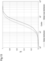
- a further technical effect is given by the fact that, giving the user the possibility to assess the effect of various distributions of defects in different regions of the part, the system according to the invention makes it possible to consider the effect of anisotropy or of non-random characteristics that could be found in the parts due to the manufacturing process.
- FIGS. 12 and 13 show examples of use of several distributions of defects.
- the use of the system according to the invention makes it possible to considerably relax the assumptions related to the distribution of the defects, description of the fatigue life, of the distribution of the sources of dispersion or of the diagram of Kitagawa (Formulation of El-Haddad or other), the relaxation of the previous hp provides more flexibility to the model to obtain a better description of the phenomenon, but does not affect the calculation time.
Landscapes
- Physics & Mathematics (AREA)
- General Physics & Mathematics (AREA)
- General Health & Medical Sciences (AREA)
- Chemical & Material Sciences (AREA)
- Analytical Chemistry (AREA)
- Biochemistry (AREA)
- Life Sciences & Earth Sciences (AREA)
- Health & Medical Sciences (AREA)
- Immunology (AREA)
- Pathology (AREA)
- Engineering & Computer Science (AREA)
- Aviation & Aerospace Engineering (AREA)
- Investigating Strength Of Materials By Application Of Mechanical Stress (AREA)
Abstract
Description
-
- a) importing predefined input data I concerning at least one part of a component to be assessed;
- b) distinguishing at least one surface region RE of the part from at least one internal region RI of said part;
- c) determining the volume and stress/deformation applied to the surface region RE and to the internal region RI (e.g., as part of the results obtained by means of finite element analysis method (FE));
- d) assigning the correct distribution of defects to all groups of elements defined by the user;
- e) determining the maximum dimension of the defect in each surface or internal region RE, RI considered;
- f) determining the critical dimension of the defect in each surface region or internal region by considering the fatigue strength of the material at the number of cycles under consideration, the position of each surface or internal region RE, RI and the stress/deformation applied on the surface region RE and on the internal region RI;
- g) calculating the reliability of at least one of the surface or internal regions RE, RI considered.
- h) determining the reliability of the entire part.
-
- finite element analysis data (FE) of the part (supported by a simulation software, e.g. Abaqus);
- input parameters for analysis;
- parameters relating to the distribution/s of the defect;
- parameters relating to the strength of the material.
-
- cycle ratio
wherein F is the applied stress;
-
- fatigue life to be assessed N;
- variability and distribution of material strength (e.g. described by Lognormal distribution and considering a given coefficient of variation);
- variability and distribution of the applied stress (e.g. described by Lognormal distribution and a given coefficient of variation);
- parameters for the description of the strength;
- number of symmetrical units Nsymm.
-
- at least one output file generated by a simulation software (e.g., Abaqus) and containing the data and results of the finite element static analysis (FE);
- at least one file containing the input parameters for analysis;
- at least one file containing the parameters relating to the distribution of the defect;
- at least one file containing the parameters relating to the strength of the material.
V=|J|·ω ξ·ωη·ωζ
where (ξ, η, ζ) are the isoparametric coordinates relating to each finite element, the terms ωξ, ωη, ωζ are the Gauss weights for such coordinates, while |J| is the determinant of the Jacobean matrix of the rigidity.
R f =∫f(x)·R V(x)·dx
-
- a map of the normalized failure probability, for a qualitative and visual assessment of the more critical regions of said part (normalization is performed automatically by the system S to improve the display of results);
- a quantitative map of the defect critical dimension;
- a quantitative map of local failure probability relating to any mesh integration point.
-
- take the grid (mesh) at input;
- determine the surface nodes;
- calculate the surface area associated with them;
- define the volume associated with such regions as a product of the area calculated for a suitably calculated thickness h.
Claims (13)
Applications Claiming Priority (3)
| Application Number | Priority Date | Filing Date | Title |
|---|---|---|---|
| IT102018000020743A IT201800020743A1 (en) | 2018-12-21 | 2018-12-21 | SYSTEM FOR THE PROBABILISTIC EVALUATION OF FATIGUE OF PARTS IN THE PRESENCE OF MANUFACTURING DEFECTS |
| IT102018000020743 | 2018-12-21 | ||
| PCT/IB2019/061016 WO2020128896A1 (en) | 2018-12-21 | 2019-12-18 | Computer-implemented method for the probabilistic assessment of fatigue of component parts in the presence of manufacturing defects and relevant system |
Publications (2)
| Publication Number | Publication Date |
|---|---|
| US20220074837A1 US20220074837A1 (en) | 2022-03-10 |
| US12007367B2 true US12007367B2 (en) | 2024-06-11 |
Family
ID=66379972
Family Applications (1)
| Application Number | Title | Priority Date | Filing Date |
|---|---|---|---|
| US17/416,435 Active 2041-02-25 US12007367B2 (en) | 2018-12-21 | 2019-12-18 | Computer-implemented method for the probabilistic assessment of fatigue of component parts in the presence of manufacturing defects and relevant system |
Country Status (4)
| Country | Link |
|---|---|
| US (1) | US12007367B2 (en) |
| EP (1) | EP3899479B1 (en) |
| IT (1) | IT201800020743A1 (en) |
| WO (1) | WO2020128896A1 (en) |
Families Citing this family (4)
| Publication number | Priority date | Publication date | Assignee | Title |
|---|---|---|---|---|
| CN113987682B (en) * | 2021-11-02 | 2024-06-21 | 电子科技大学 | A probabilistic fatigue life prediction method for notched structures based on weighted coupled weakest link model |
| CN116663190B (en) * | 2023-06-06 | 2023-11-07 | 嘉丰盛精密电子科技(孝感)有限公司 | Method for identifying splicing strength of stamping parts in shielding cover |
| US12346544B2 (en) * | 2023-11-08 | 2025-07-01 | Jmp Statistical Discovery Llc | Systems, methods, and graphical user interfaces for adaptive design exploration and model management |
| CN120611159B (en) * | 2025-08-06 | 2025-10-21 | 天津市新宇彩板有限公司 | Metal pitting defect degree assessment method and system based on artificial intelligence |
Citations (4)
| Publication number | Priority date | Publication date | Assignee | Title |
|---|---|---|---|---|
| EP2909760A1 (en) | 2012-10-16 | 2015-08-26 | Siemens Aktiengesellschaft | Method and system for probabilistic fatigue crack life estimation |
| CN107563054A (en) | 2017-08-31 | 2018-01-09 | 北京航空航天大学 | A kind of turbine disk life expectance analysis method of the Weakest Link methods based on SWT parameters |
| CN108344372A (en) * | 2017-01-23 | 2018-07-31 | 通用电气公司 | The method for making and monitoring the component with integral type strain indicator |
| US20190166673A1 (en) * | 2017-11-30 | 2019-05-30 | Osram Gmbh | External assessment device for a lighting system and method of assessing a lighting system |
-
2018
- 2018-12-21 IT IT102018000020743A patent/IT201800020743A1/en unknown
-
2019
- 2019-12-18 WO PCT/IB2019/061016 patent/WO2020128896A1/en not_active Ceased
- 2019-12-18 US US17/416,435 patent/US12007367B2/en active Active
- 2019-12-18 EP EP19836561.1A patent/EP3899479B1/en active Active
Patent Citations (4)
| Publication number | Priority date | Publication date | Assignee | Title |
|---|---|---|---|---|
| EP2909760A1 (en) | 2012-10-16 | 2015-08-26 | Siemens Aktiengesellschaft | Method and system for probabilistic fatigue crack life estimation |
| CN108344372A (en) * | 2017-01-23 | 2018-07-31 | 通用电气公司 | The method for making and monitoring the component with integral type strain indicator |
| CN107563054A (en) | 2017-08-31 | 2018-01-09 | 北京航空航天大学 | A kind of turbine disk life expectance analysis method of the Weakest Link methods based on SWT parameters |
| US20190166673A1 (en) * | 2017-11-30 | 2019-05-30 | Osram Gmbh | External assessment device for a lighting system and method of assessing a lighting system |
Non-Patent Citations (3)
| Title |
|---|
| Torries Brian et al: "Overview on Microstructure- and Defect-Sensitive Fatigue Modeling of Additively Manufactured Materials", JOM Journal of Metals, Springer New York LLC, United States, vol. 70, No. 9, Jul. 25, 2018, pp. 1853-1862, XP036570396, ISSN: 1047-4838. |
| Ws Johnson et al: "Probabilistic Aspects of Life Prediction" IN: "ASTM International. Journal", Jan. 1, 2004, ASTM International, US, XP055403629, ISSN: 1546-962X, vol. 1, pp. ii-276. |
| Y. Hong et al., "Parallel Reflective Symmetry Transformation for Volume Data", Eurographics Symposium on Parallel Graphics and Visualization (2007), https://www.sciencedirect.com/science/article/pii/S009784930700204X. * |
Also Published As
| Publication number | Publication date |
|---|---|
| EP3899479A1 (en) | 2021-10-27 |
| EP3899479B1 (en) | 2024-04-03 |
| EP3899479C0 (en) | 2024-04-03 |
| IT201800020743A1 (en) | 2020-06-21 |
| WO2020128896A1 (en) | 2020-06-25 |
| US20220074837A1 (en) | 2022-03-10 |
Similar Documents
| Publication | Publication Date | Title |
|---|---|---|
| US12007367B2 (en) | Computer-implemented method for the probabilistic assessment of fatigue of component parts in the presence of manufacturing defects and relevant system | |
| Chen et al. | Model validation via uncertainty propagation and data transformations | |
| Giannella | Uncertainty quantification in fatigue crack-growth predictions: V. Giannella | |
| Hales et al. | Verification of the BISON fuel performance code | |
| Peng et al. | Life cycle reliability assessment of new products—A Bayesian model updating approach | |
| US7877229B2 (en) | Computational method for load enhancement factors and apparatus for executing same | |
| Olson et al. | A new mechanical method for biaxial residual stress mapping | |
| Melson | Fatigue crack growth analysis with finite element methods and a monte carlo simulation | |
| Sankararaman et al. | Uncertainty quantification in fatigue damage prognosis | |
| Gottschalk et al. | Shape gradients for the failure probability of a mechanic component under cyclic loading: a discrete adjoint approach | |
| Ozkan et al. | Determination of theoretical stress concentration factor for circular/elliptical holes with reinforcement using analytical, finite element method and artificial neural network techniques | |
| Zaitseva et al. | High performance computing for aircraft assembly optimization | |
| Marques Ferreira et al. | Stochastic assessment of burst pressure for corroded pipelines | |
| CN116227045B (en) | A local stress and strain field construction method and system for structural specimens | |
| Ocampo et al. | An ultrafast crack growth lifing model to support digital twin, virtual testing, and probabilistic damage tolerance applications | |
| Wang et al. | Bivariate Fourier-series-based prediction of surface residual stress fields using stresses of partial points | |
| Karlson et al. | Sandia Fracture Challenge 3: detailing the Sandia Team Q failure prediction strategy | |
| Dvurecenska et al. | The validation of a full-field deformation analysis of an aircraft panel: A case study | |
| Salmi et al. | Numerical Study of SIF for a Crack in P265GH Steel by XFEM | |
| Duan et al. | The numerical simulation of fatigue crack propagation in Inconel 718 alloy at different temperatures | |
| Xu et al. | Identify structural flaw location and type with an inverse algorithm of resonance inspection | |
| Rodrigues et al. | Damage index proposals applied to quasi-brittle materials simulated using the lattice discrete element method | |
| Allen | SDE models with exponential drift and diffusion for approximating fatigue crack growth dynamics | |
| Valente et al. | Parameter identification and shape optimization: An integrated methodology in metal forming and structural applications | |
| Momin et al. | A non-intrusive method to add finite element-based random variables to a probabilistic design code |
Legal Events
| Date | Code | Title | Description |
|---|---|---|---|
| FEPP | Fee payment procedure |
Free format text: ENTITY STATUS SET TO UNDISCOUNTED (ORIGINAL EVENT CODE: BIG.); ENTITY STATUS OF PATENT OWNER: SMALL ENTITY |
|
| FEPP | Fee payment procedure |
Free format text: ENTITY STATUS SET TO SMALL (ORIGINAL EVENT CODE: SMAL); ENTITY STATUS OF PATENT OWNER: SMALL ENTITY |
|
| AS | Assignment |
Owner name: POLITECNICO DI MILANO, ITALY Free format text: ASSIGNMENT OF ASSIGNORS INTEREST;ASSIGNORS:BERETTA, STEFANO;ROMANO, SIMONE;MICCOLI, STEFANO;SIGNING DATES FROM 20210726 TO 20210727;REEL/FRAME:057071/0899 |
|
| STPP | Information on status: patent application and granting procedure in general |
Free format text: DOCKETED NEW CASE - READY FOR EXAMINATION |
|
| STPP | Information on status: patent application and granting procedure in general |
Free format text: NON FINAL ACTION MAILED |
|
| STPP | Information on status: patent application and granting procedure in general |
Free format text: RESPONSE TO NON-FINAL OFFICE ACTION ENTERED AND FORWARDED TO EXAMINER |
|
| STPP | Information on status: patent application and granting procedure in general |
Free format text: NOTICE OF ALLOWANCE MAILED -- APPLICATION RECEIVED IN OFFICE OF PUBLICATIONS |
|
| STPP | Information on status: patent application and granting procedure in general |
Free format text: PUBLICATIONS -- ISSUE FEE PAYMENT RECEIVED |
|
| STPP | Information on status: patent application and granting procedure in general |
Free format text: PUBLICATIONS -- ISSUE FEE PAYMENT VERIFIED |
|
| STCF | Information on status: patent grant |
Free format text: PATENTED CASE |