US12005807B2 - Method for control power of battery, control apparatus, and electric vehicle - Google Patents
Method for control power of battery, control apparatus, and electric vehicle Download PDFInfo
- Publication number
- US12005807B2 US12005807B2 US17/013,630 US202017013630A US12005807B2 US 12005807 B2 US12005807 B2 US 12005807B2 US 202017013630 A US202017013630 A US 202017013630A US 12005807 B2 US12005807 B2 US 12005807B2
- Authority
- US
- United States
- Prior art keywords
- power
- battery
- charge
- discharge
- comparison
- Prior art date
- Legal status (The legal status is an assumption and is not a legal conclusion. Google has not performed a legal analysis and makes no representation as to the accuracy of the status listed.)
- Active, expires
Links
Images


Classifications
-
- B—PERFORMING OPERATIONS; TRANSPORTING
- B60—VEHICLES IN GENERAL
- B60L—PROPULSION OF ELECTRICALLY-PROPELLED VEHICLES; SUPPLYING ELECTRIC POWER FOR AUXILIARY EQUIPMENT OF ELECTRICALLY-PROPELLED VEHICLES; ELECTRODYNAMIC BRAKE SYSTEMS FOR VEHICLES IN GENERAL; MAGNETIC SUSPENSION OR LEVITATION FOR VEHICLES; MONITORING OPERATING VARIABLES OF ELECTRICALLY-PROPELLED VEHICLES; ELECTRIC SAFETY DEVICES FOR ELECTRICALLY-PROPELLED VEHICLES
- B60L58/00—Methods or circuit arrangements for monitoring or controlling batteries or fuel cells, specially adapted for electric vehicles
- B60L58/10—Methods or circuit arrangements for monitoring or controlling batteries or fuel cells, specially adapted for electric vehicles for monitoring or controlling batteries
- B60L58/12—Methods or circuit arrangements for monitoring or controlling batteries or fuel cells, specially adapted for electric vehicles for monitoring or controlling batteries responding to state of charge [SoC]
- B60L58/13—Maintaining the SoC within a determined range
-
- H—ELECTRICITY
- H02—GENERATION; CONVERSION OR DISTRIBUTION OF ELECTRIC POWER
- H02J—ELECTRIC POWER NETWORKS; CIRCUIT ARRANGEMENTS OR SYSTEMS FOR SUPPLYING OR DISTRIBUTING ELECTRIC POWER; SYSTEMS FOR STORING ELECTRIC ENERGY
- H02J7/00—Circuit arrangements for charging or discharging batteries or for supplying loads from batteries
- H02J7/80—Circuit arrangements for charging or discharging batteries or for supplying loads from batteries including monitoring or indicating arrangements
- H02J7/82—Control of state of charge [SOC]
-
- B—PERFORMING OPERATIONS; TRANSPORTING
- B60—VEHICLES IN GENERAL
- B60L—PROPULSION OF ELECTRICALLY-PROPELLED VEHICLES; SUPPLYING ELECTRIC POWER FOR AUXILIARY EQUIPMENT OF ELECTRICALLY-PROPELLED VEHICLES; ELECTRODYNAMIC BRAKE SYSTEMS FOR VEHICLES IN GENERAL; MAGNETIC SUSPENSION OR LEVITATION FOR VEHICLES; MONITORING OPERATING VARIABLES OF ELECTRICALLY-PROPELLED VEHICLES; ELECTRIC SAFETY DEVICES FOR ELECTRICALLY-PROPELLED VEHICLES
- B60L58/00—Methods or circuit arrangements for monitoring or controlling batteries or fuel cells, specially adapted for electric vehicles
- B60L58/10—Methods or circuit arrangements for monitoring or controlling batteries or fuel cells, specially adapted for electric vehicles for monitoring or controlling batteries
- B60L58/12—Methods or circuit arrangements for monitoring or controlling batteries or fuel cells, specially adapted for electric vehicles for monitoring or controlling batteries responding to state of charge [SoC]
- B60L58/14—Preventing excessive discharging
-
- G—PHYSICS
- G01—MEASURING; TESTING
- G01R—MEASURING ELECTRIC VARIABLES; MEASURING MAGNETIC VARIABLES
- G01R31/00—Arrangements for testing electric properties; Arrangements for locating electric faults; Arrangements for electrical testing characterised by what is being tested not provided for elsewhere
- G01R31/36—Arrangements for testing, measuring or monitoring the electrical condition of accumulators or electric batteries, e.g. capacity or state of charge [SoC]
- G01R31/382—Arrangements for monitoring battery or accumulator variables, e.g. SoC
-
- H—ELECTRICITY
- H01—ELECTRIC ELEMENTS
- H01M—PROCESSES OR MEANS, e.g. BATTERIES, FOR THE DIRECT CONVERSION OF CHEMICAL ENERGY INTO ELECTRICAL ENERGY
- H01M10/00—Secondary cells; Manufacture thereof
- H01M10/42—Methods or arrangements for servicing or maintenance of secondary cells or secondary half-cells
- H01M10/425—Structural combination with electronic components, e.g. electronic circuits integrated to the outside of the casing
- H01M10/4257—Smart batteries, e.g. electronic circuits inside the housing of the cells or batteries
-
- H—ELECTRICITY
- H02—GENERATION; CONVERSION OR DISTRIBUTION OF ELECTRIC POWER
- H02J—ELECTRIC POWER NETWORKS; CIRCUIT ARRANGEMENTS OR SYSTEMS FOR SUPPLYING OR DISTRIBUTING ELECTRIC POWER; SYSTEMS FOR STORING ELECTRIC ENERGY
- H02J7/00—Circuit arrangements for charging or discharging batteries or for supplying loads from batteries
- H02J7/90—Regulation of charging or discharging current or voltage
- H02J7/933—Regulation of charging or discharging current or voltage the cycle being controlled or terminated in response to electric parameters
-
- B—PERFORMING OPERATIONS; TRANSPORTING
- B60—VEHICLES IN GENERAL
- B60L—PROPULSION OF ELECTRICALLY-PROPELLED VEHICLES; SUPPLYING ELECTRIC POWER FOR AUXILIARY EQUIPMENT OF ELECTRICALLY-PROPELLED VEHICLES; ELECTRODYNAMIC BRAKE SYSTEMS FOR VEHICLES IN GENERAL; MAGNETIC SUSPENSION OR LEVITATION FOR VEHICLES; MONITORING OPERATING VARIABLES OF ELECTRICALLY-PROPELLED VEHICLES; ELECTRIC SAFETY DEVICES FOR ELECTRICALLY-PROPELLED VEHICLES
- B60L2240/00—Control parameters of input or output; Target parameters
- B60L2240/40—Drive Train control parameters
- B60L2240/54—Drive Train control parameters related to batteries
- B60L2240/547—Voltage
-
- H—ELECTRICITY
- H01—ELECTRIC ELEMENTS
- H01M—PROCESSES OR MEANS, e.g. BATTERIES, FOR THE DIRECT CONVERSION OF CHEMICAL ENERGY INTO ELECTRICAL ENERGY
- H01M10/00—Secondary cells; Manufacture thereof
- H01M10/42—Methods or arrangements for servicing or maintenance of secondary cells or secondary half-cells
- H01M10/425—Structural combination with electronic components, e.g. electronic circuits integrated to the outside of the casing
- H01M2010/4271—Battery management systems including electronic circuits, e.g. control of current or voltage to keep battery in healthy state, cell balancing
-
- Y—GENERAL TAGGING OF NEW TECHNOLOGICAL DEVELOPMENTS; GENERAL TAGGING OF CROSS-SECTIONAL TECHNOLOGIES SPANNING OVER SEVERAL SECTIONS OF THE IPC; TECHNICAL SUBJECTS COVERED BY FORMER USPC CROSS-REFERENCE ART COLLECTIONS [XRACs] AND DIGESTS
- Y02—TECHNOLOGIES OR APPLICATIONS FOR MITIGATION OR ADAPTATION AGAINST CLIMATE CHANGE
- Y02E—REDUCTION OF GREENHOUSE GAS [GHG] EMISSIONS, RELATED TO ENERGY GENERATION, TRANSMISSION OR DISTRIBUTION
- Y02E60/00—Enabling technologies; Technologies with a potential or indirect contribution to GHG emissions mitigation
- Y02E60/10—Energy storage using batteries
-
- Y—GENERAL TAGGING OF NEW TECHNOLOGICAL DEVELOPMENTS; GENERAL TAGGING OF CROSS-SECTIONAL TECHNOLOGIES SPANNING OVER SEVERAL SECTIONS OF THE IPC; TECHNICAL SUBJECTS COVERED BY FORMER USPC CROSS-REFERENCE ART COLLECTIONS [XRACs] AND DIGESTS
- Y02—TECHNOLOGIES OR APPLICATIONS FOR MITIGATION OR ADAPTATION AGAINST CLIMATE CHANGE
- Y02T—CLIMATE CHANGE MITIGATION TECHNOLOGIES RELATED TO TRANSPORTATION
- Y02T10/00—Road transport of goods or passengers
- Y02T10/60—Other road transportation technologies with climate change mitigation effect
- Y02T10/70—Energy storage systems for electromobility, e.g. batteries
Definitions
- the disclosure relates to a battery, and particularly relates to a method for controlling a power of a battery, a control apparatus, and an electric vehicle.
- Embodiments of the disclosure provide a method for controlling a power of a battery, a control apparatus, and an electric vehicle capable of effectively utilizing the energy of the battery.
- an embodiment of the disclosure provides a method for controlling a power of a battery.
- the method includes: obtaining rated powers of the battery and a current actual power of the battery; and adjusting the actual power according to a difference between the rated powers and the current actual power when the current actual power is greater than or equal to the rated powers.
- an embodiment of the disclosure provides a control apparatus for a power of a battery.
- the control apparatus includes an obtainer and an adjuster.
- the obtainer is configured for obtaining rated powers of the battery and a current actual power of the battery.
- the adjuster is configured for adjusting the actual power according to a difference between the rated powers and the current actual power when the current actual power is greater than or equal to the rated powers.
- an embodiment of the disclosure provides an electric vehicle including a battery and a controller.
- the controller includes the control apparatus according to the embodiments of the disclosure, or the controller controls a power of the battery according to the method according to the embodiments of the disclosure.
- the control apparatus for the power of the battery, and the electric vehicle by adjusting the actual power according to a difference between the rated powers and the current actual power, the power output by the battery and the power fed back to the battery can be optimized.
- FIG. 1 is a flowchart illustrating a method for controlling a power of a battery according to an embodiment of the disclosure.
- FIG. 2 is a schematic diagram illustrating dynamically adjusting a battery output power according to an embodiment of the disclosure.
- FIG. 3 is a schematic diagram illustrating dynamically adjusting a power fed back to a battery according to an embodiment of the disclosure.
- FIG. 4 is a schematic view illustrating results of discharge peak power of a battery cell under different temperatures and different states of charge (SOCs).
- FIG. 5 is a schematic view illustrating results of discharge rated power of a battery cell under different temperatures and different SOCs.
- FIG. 6 is a schematic view illustrating results of charge peak power of a battery cell under different temperatures and different SOCs.
- FIG. 7 is a schematic view illustrating results of charge rated power of a battery cell under different temperatures and different SOCs.
- FIG. 8 is a flowchart illustrating a method according to Example 1.
- FIG. 9 is a flowchart illustrating a method according to Example 2.
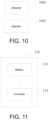
- FIG. 10 is a schematic view illustrating a structure of a control apparatus for a power of a battery according to an embodiment of the disclosure.
- FIG. 11 is a schematic view illustrating a structure of an electric vehicle according to an embodiment of the disclosure.
- FIG. 12 is another flowchart illustrating a method for controlling a power of a battery according to an embodiment of the disclosure.
- FIG. 13 is another schematic view illustrating a structure of a control apparatus for a power of a battery according to an embodiment of the disclosure.
- first”, “second” and the like are only used for illustrative purposes and are not to be construed as expressing or implying a relative importance.
- the term “plurality” is two or more.
- the term “and/or” includes any and all combinations of one or more of the associated listed items.
- An embodiment of the disclosure provides a method for controlling a power of a battery. As shown in FIG. 1 , the method includes the following.
- Step S 101 Obtain the rated powers of the battery and a current actual power of the battery.
- the rated powers and/or the peak powers of the battery are construed as prescribed power parameters.
- a battery management system may periodically transmit the prescribed power parameters to a control apparatus, such as, but not limited to, transmitting the prescribed power parameters every 0.1 s, so that the control apparatus obtains the prescribed power parameters.
- the prescribed power parameters may be construed as the power parameters predetermined in the battery, such as a predetermined discharge rated power and a predetermined charge rated power.
- the current power of the battery may be obtained periodically or obtained at any time. That is, the time when the current power of the battery is obtained may be set based on practical needs.
- any process well-known by people skilled in the art for obtaining the current power of the battery may be adopted when obtaining the current power of the battery.
- the disclosure is not particularly limited in this regard.
- Step S 102 Adjust the actual power according to a difference between the rated powers and the current actual power when the current actual power is greater than or equal to the rated powers.
- the embodiment of the disclosure by adjusting the actual power according to a difference between the rated powers and the current actual power, the power output by the battery and the power fed back to the battery can be optimized. Accordingly, the energy of the battery can be utilized effectively to avoid excessive use of the battery while ensuring that the energy released by the battery satisfies the need of the electric vehicle for power. Therefore, the embodiment of the disclosure exhibits crucial effects in facilitating the performance of the electric vehicle, avoiding an operation failure of the battery, elongating the lifetime of the battery, etc.
- the prescribed power parameters further includes peak powers.
- a maximum power output by the battery is controlled to be not greater than the rated powers after a power output by the battery is controlled to drop the power to the rated powers when the current actual power is greater than the peak powers.
- a maximum power output by the battery is controlled to be not greater than peak powers when the current actual power is less than the rated powers.
- adjusting the actual power according to the comparison power includes: controlling a maximum power output by the battery to be not greater than the peak powers, or to drop the power to the rated powers according to the comparison power.
- an embodiment of the disclosure provides a method for controlling a power of a battery. As shown in FIG. 12 , the method includes the following.
- Step S 201 Obtain rated powers and peak powers of the battery, and a current actual power of the battery.
- the rated powers and/or the peak powers of the battery are construed as prescribed power parameters.
- the prescribed power parameters may include a discharge rated power and a charge rated power.
- a battery management system may periodically transmit the prescribed power parameters to a control apparatus, such as, but not limited to, transmitting the prescribed power parameters every 0.1 s, so that the control apparatus obtains the prescribed power parameters.
- the prescribed power parameters may be construed as the power parameters predetermined in the battery, such as a predetermined discharge rated power and a predetermined charge rated power.
- the current power of the battery may be obtained periodically or obtained at any time. That is, the time when the current power of the battery is obtained may be set based on practical needs.
- any process well-known by people skilled in the art for obtaining the current power of the battery may be adopted when obtaining the current power of the battery.
- the disclosure is not particularly limited in this regard.
- Step S 202 Determine a difference between the peak powers and the rated power according to the rated power and the peak powers.
- the reference power may include a discharge reference power or a charge reference power.
- Step S 203 Determine a difference between the current actual power and the prescribed power parameters according to the prescribed power parameters and the current actual power.
- the comparison power may include a discharge comparison power and/or a charge comparison power.
- a difference between the peak powers and the rated powers is construed as a comparison power.
- a difference between the current actual power and the prescribed power parameters is construed as a reference power.
- Step S 204 Adjust the actual power according to the reference power and the comparison power.
- the embodiment of the disclosure by adjusting the actual power according to the reference power and the comparison power, the power output by the battery and the power fed back to the battery can be optimized. Accordingly, the energy of the battery can be utilized effectively to avoid excessive use of the battery while ensuring that the energy released by the battery satisfies the need of the electric vehicle for power. Therefore, the embodiment of the disclosure exhibits crucial effects in facilitating the performance of the electric vehicle, avoiding an operation failure of the battery, elongating the lifetime of the battery, etc.
- the prescribed power parameters include a discharge peak power or a charge peak power
- the prescribed power parameters further include the discharge rated power or the charge rated power
- the methods as follows may be adopted to determine the reference power and the comparison power.
- a difference between the peak powers and the rated powers is determined according to the rated powers and the peak powers.
- determining a difference between the peak powers and the rated powers according to the rated powers and the peak powers includes: calculating the discharge reference power according to a difference between the discharge peak power and the discharge rated power; and calculating the charge reference power according to a difference between the charge peak power and the charge rated power.
- T represents a temperature
- SOC represents a state of charge
- t1 represents a time of applying a discharge power to the battery
- t2 represents a time of applying a charge power to the battery
- S 1_d represents the discharge reference power
- S 1_c represents the charge reference power
- P d_m (SOC, T, t1) represents the discharge peak power when the temperature is T, the state of charge of the battery is SOC
- P d_r SOC, T, t1
- P c_m represents the charge peak power when the temperature is T, the state of charge of the battery is SOC
- P c_r represents the charge rated power when the temperature is T, the state of charge of the battery is SOC
- P c_r represents the charge rated power when the temperature is T, the state of charge of the battery is SOC
- P c_r represents the charge rated power when the temperature is T, the state of charge of the battery is SOC
- P c_r represents the charge rated power when
- t1 may be set as 30 s, but is not limited to 30 s
- t2 may be set as 10 s, but is not limited to 10 s.
- the values of t1 and t2 may be set according to practical situations to satisfy the needs under various scenarios and provide flexibility in design.
- the reference power can be determined through a simple method, and the actual power can be adjusted by using the reference power. As a result, the control over the power of the battery can be realized.
- determining a difference between the current actual power and the prescribed power parameters according to the prescribed power parameters and the current actual power includes: performing an integral process on a difference between the current actual power and the discharge rated power to obtain the discharge comparison power; performing an integral process on a difference between the current actual power and the charge rated power to obtain the charge comparison power.
- T represents the temperature
- SOC represents the state of charge
- t1 represents the time of applying the discharge power to the battery
- t2 represents the time of applying the charge power to the battery
- S2_d represents the discharge comparison power
- S2_c represents the charge comparison power
- Pd_r(SOC, T, t1) represents the discharge rated power when the temperature is T, the state of charge of the battery is SOC
- the time of applying the discharge power is t1
- Pc_r(SOC, T, t2) represents the charge rated power when the temperature is T, the state of charge of the battery is SOC
- the time of applying the charge power is t2
- a and b are time parameters
- P1 represents the actual power output by the battery.
- the comparison power can be determined through a simple method, and the actual power can be adjusted by using the comparison power. As a result, the control over the power of the battery can be realized.
- a difference between the peak powers and the rated power is determined according to the rated power and the peak powers.
- determining a difference between the peak powers and the rated power according to the rated power and the peak power includes: performing an integral process on the discharge peak power to calculate the discharge reference power; or performing an integral process on the charge peak power to determine the charge reference power.
- determine a difference between the current actual power and the prescribed power parameters according to the prescribed power parameters and the current actual power specifically includes: performing an integral process on the current actual power to obtain the discharge comparison power; or performing an integral process on the current actual power to obtain the charge comparison power.
- Method 1 and Method 2 above other methods may also be adopted to determine the reference power and the comparison power, such as, but not limited to, performing an integral process on the difference between the current actual power and the peak power (including the discharge peak power or the charge peak power) to obtain the comparison power or performing an integral process on a ratio between the current actual power and the peak power to obtain the comparison power; or performing an integral process on a ratio between the current actual power and the rated power (including the discharge rated power or the charge rated power) to obtain the comparison power, etc.
- performing an integral process on the difference between the current actual power and the peak power including the discharge peak power or the charge peak power
- performing an integral process on a ratio between the current actual power and the peak power to obtain the comparison power
- performing an integral process on a ratio between the current actual power and the rated power including the discharge rated power or the charge rated power
- the reference power and the comparison power may also be obtained by performing an averaging process or other processes, such as, but not limited to, performing an averaging process on the difference between the current actual power and the peak power (including the discharge peak power or the charge peak power) to obtain the comparison power; or performing an averaging process on the ratio between the current actual power and the peak power to obtain the comparison power; or performing an averaging process on the ratio between the current actual power and the rated power (including the discharge rated power or the charge rated power) to obtain the comparison power, etc., just to name a few.
- the method when determining the reference power and the comparison power, the method may be designed according to practical needs, as long as the reference power and the comparison power can be determined for the subsequent adjustment to the actual power.
- the disclosure does not intend to impose a specific limitation on the specific details of the determining method.
- adjusting the actual power according to the reference power and the comparison power includes: adjusting the actual power according to the reference power and the comparison power under the condition that a predetermined control rule is satisfied.
- the predetermined control rule may include, within a prescribed time, an actual polarization voltage of the battery being not greater than a maximum polarization voltage of the battery, and an actual amount of accumulated heat of the battery being not greater than a maximum amount of accumulated heat of the battery.
- the prescribed power parameters include the discharge peak power or the charge peak power, and the prescribed time is the time adopted for obtaining the discharge peak power.
- t represents time, and the value range of t is set as [0, t0], t0 being the prescribed time
- ⁇ U max (t0) represents the maximum polarization voltage of the battery within the prescribed time
- ⁇ Us(t) represents the actual polarization voltage of the battery within the arbitrary time t
- I max 2 ⁇ R ⁇ t0 represents the amount of accumulated heat of the battery within the prescribed time
- Is 2 ⁇ t represents the actual amount of accumulated heat of the battery within the arbitrary time t
- Is represents a current generated by the battery at the arbitrary time t
- I max represents the maximum current generated by the battery
- R represents the internal resistance of the battery under a specific temperature, a specific SOC, and a specific current.
- the prescribed time is the time adopted for obtaining the discharge peak power, and may be determined by referring to the Hybrid Pulse Power Characteristic (HPPC) test when determining the discharge peak power of the battery. Therefore, the prescribed time is normally set as 30 s. However, the disclosure is not limited thereto, and the prescribed time may also be set based on practical situations.
- the battery may generate a polarization voltage through use of the battery. If the polarization voltage is higher, the performance of the battery is lower, and the power that is actual output is decreased.
- the battery may generate heat through use of the battery.
- a larger amount of accumulated heat in the battery within the prescribed time indicates that the battery has generated a great amount of heat, so the temperature of the battery may increase.
- the internal structure of the battery may be damaged, and the performance of the battery may thus be affected.
- the control rule needs to be satisfied during the process of controlling the output power of the battery, so as to facilitate the performance and increase the endurance of the battery.
- adjusting the actual power according to the reference power and the comparison power includes: controlling the maximum power output by the battery to be not greater than the discharge peak power or to drop the maximum power to the discharge rated power according to the discharge reference power and the discharge comparison power if the battery is currently in a discharging stage, the actual power is a discharge actual power, the reference power is the discharge reference power, the comparison power is the discharge comparison power, and the prescribed power parameters include the discharge peak power or the discharge rated power; or controlling the maximum power fed back to the battery to be not greater than the charge peak power or to drop the maximum power to the charge rated power according to the charge reference power and the charge comparison power if the battery is currently in a charging stage, the actual power is a charge actual power, the reference power is the charge reference power, the comparison power is the charge comparison power, and the prescribed power parameters include the charge peak power or the charge rated power.
- the actual power of the battery may include: the actual power output by the battery during the discharge process and the actual power fed back to the battery during the charge process.
- the maximum power output by the battery may be construed as the maximum value in the actual power output by the battery
- the maximum power fed back to the battery may correspondingly be construed as the maximum value in the actual power fed back to the battery.
- the battery when the battery is applied to the electric vehicle, the needs of the electric vehicle for power may be associated with the actual charge and discharge capabilities of the battery.
- the maximum power output by/fed back to the battery can be dynamically switched between the discharge/charge peak power and the discharge/charge rated power.
- an optimized design for the power of the battery can be realized. Accordingly, the energy of the battery can be utilized effectively, and the battery can be prevented from being used excessively while ensuring that the energy released by the battery satisfies the need of the electric vehicle for power. Therefore, the embodiment of the disclosure exhibits crucial effects in facilitating the performance of the electric vehicle, avoiding an operation failure of the battery, elongating the lifetime of the battery, etc.
- controlling the maximum power output by the battery to be not greater than the discharge peak power or to drop the maximum power to the discharge rated power according to the discharge reference power and the discharge comparison power specifically includes: determining whether the discharge comparison power is greater than N1 times of the discharge reference power; if the discharge comparison power is not greater than N1 times of the discharge reference power, controlling the maximum power output by the battery to be not greater than the discharge peak power; if the discharge comparison power is greater than N1 times of the discharge reference power, further determining whether the discharge comparison power is greater than N2 times of the discharge reference power; if the discharge comparison power is greater than N2 times of the discharge reference power, controlling the maximum power output by the battery to be not greater than the discharge rated power after controlling the power output by the battery to drop the power to the discharge rated power; and if the discharge comparison power is not greater than N2 times of the discharge reference power, controlling the maximum power output by the battery to be not greater than the discharge peak power.
- Controlling the maximum power fed back to the battery to be not greater than the charge peak power or to drop the power to the charge rated power according to the charge reference power and the charge comparison power specifically includes: determining whether the charge comparison power is less than N1 times of the charge reference power; if the charge comparison power is not less than N1 times of the charge reference power, controlling the absolute value of the maximum power fed back to the battery to be not greater than the absolute value of the charge peak power; if the charge comparison power is less than N1 times of the charge reference power, further determining whether the charge comparison power is less than N2 times of the charge reference power; if the charge comparison power is less than N2 times of the charge reference power, controlling the absolute value of the maximum power fed back to the battery to be not greater than the absolute value of the charge rated power after controlling the absolute value of the power fed back to the battery to drop the absolute value of the power to the absolute value of the charge rated power; if the charge comparison power is not less than N2 times of the charge reference power, controlling the absolute value of the maximum power fed back to
- the maximum power which the battery allows to output can be dynamically switched between the discharge peak power and the absolute value of the charge peak power, and the maximum power input to the battery can be dynamically switched between the discharge rated power and the absolute value of the charge rated power.
- the design controls the power output of the battery while ensuring stable and effective use of the battery for a long time. Such design serves as an effective example for the applications of batteries in electric vehicles.
- the discharge process may be construed as, but not limited to, the traveling process of the electric vehicle. At this time, the discharge peak power, the discharge rated power, and the current actual power during the discharge process may all be defined as positive values. Meanwhile, the charge process may be construed as, but not limited to, the braking process of the electric vehicle. At this time, the charge peak power, the charge rated power, and the current actual power during the charge process may all be defined as negative values. Accordingly, the charge process and the discharge process are distinguished from each other, so as to effectively control the power of the battery.
- the charge peak power, the charge rated power, and the current actual power during the charge process may all be defined as positive values and may be set according to practical needs to satisfy the needs under various scenarios and provide flexibility in design.
- the adjustment made to the actual power may differ.
- the descriptions are made, as example, by using the reference power and the comparison power determined according to Method 1 and Method 2 described above.
- the discharge comparison power determined according to Method 1 is obtained according to the integral of the difference between the current actual power and the discharge rated power, whether the discharge comparison power is greater than the first threshold may be first determined, and then whether the discharge comparison power is greater than N1 times of the discharge reference power is determined, so as to accurately control the actual power output by the battery.
- the value of the first threshold may be set as 0 or other values, and may be set according to practical situations.
- the disclosure is not particularly limited in this regard.
- the discharge comparison power is not greater than the first threshold, when the first threshold is zero, the current output power of the battery is less than the discharge rated power. At this time, for the ease of control, the discharge comparison power may be construed as zero. In addition, in order to allow the electric vehicle to accelerate, climb uphill, etc., during traveling, the maximum power which the battery allows to output may be controlled as the discharge peak power.
- the discharge comparison power is greater than the first threshold, when the first threshold is zero, the current output power of the battery is greater than the discharge rated power. At this time, whether the discharge comparison power is greater than N1 times of the discharge reference power may be further determined.
- the discharge comparison power is not greater than N1 times of the discharge reference power, the current output power of the battery is not the discharge peak power, and the output power is closer to the discharge rated power. Therefore, the maximum power output by the battery may be controlled to be not greater than the discharge peak power, so that the electric vehicle can accelerate, climb uphill, etc., during traveling.
- discharge comparison power is greater than N1 times of the discharge reference power, whether the discharge comparison power is greater than N2 times of the discharge reference power may be further determined.
- the discharge comparison power is greater than N2 times of the discharge reference power, the current output power of the battery is relatively large, and the output power is possibly the discharge peak power. If the battery outputs a greater power for a long time, the battery may be used excessively, the power may be lost rapidly, and the polarization voltage and the amount of accumulated heat of the battery may increase, which cause adverse effects to the performance of the battery. Therefore, at this time, the output power of the battery may be controlled to drop to the discharge rated power, then the maximum power output by the battery may be controlled to be not greater than the discharge rated power.
- such a process may specifically include controlling the battery to smoothly drop the output power from the current output power to the discharge rated power at a first predetermined rate.
- the value of the first predetermined rate is not particularly limited herein, but may be set according to practical situations, so as to satisfy the needs under various scenarios and provide flexibility in design.
- the maximum power output by the battery may be controlled to be not greater than the discharge peak power, so that the electric vehicle can accelerate, climb uphill, etc., during traveling.
- part (a) in FIG. 2 is a schematic diagram illustrating the output power of the battery during an experimental stage
- part (b) in FIG. 2 is a schematic diagram illustrating the output power of the battery during the operating mode.
- the duration during which the battery outputs the discharge peak power is 30 s, and the duration during which the battery outputs the discharge rated power is also 30 s.
- the battery alternately outputs the discharge peak power and the discharge rated power.
- the regions filled with oblique lines represent the discharge reference power.
- the broken line represents the power which the battery is able to undertake, that is, the maximum power which the battery allows to output.
- the regions filled with sparse dots represent the discharge comparison power.
- t3 may be, but not limited to, greater than or equal to 24 s
- t4 may be, but not limited to, less than or equal to 12 s.
- the power output by the battery drops at the first predetermined rate until the discharge rated power.
- the power output by the battery varies within the power range which the battery is able to undertake, the power output by the battery is controlled while the battery is ensured to operate effectively and normally. Accordingly, an optimized design of the operating mode of the battery is realized.
- whether the charge comparison power is less than N1 times of the charge reference power whether the charge comparison power is less than a second threshold also needs to be determined first.
- the charge comparison power, the charge peak power, and the current actual power of the battery in the charging stage of the battery are all negative values.
- the value of the second threshold may be set as 0 or other values, and may be set according to practical situations.
- the disclosure is not particularly limited in this regard.
- the charge comparison power is not less than the second threshold, when the second threshold is zero, the current power fed back to the battery is less than the charge rated power. At this time, for the ease of control, the charge comparison power may be construed as zero. In addition, the maximum power fed back to the battery may be controlled as the charge peak power.
- controlling the absolute value of the power fed back to the battery to drop the absolute value of the power to the absolute value of the charge rated power may be realized by controlling the absolute value of the current power fed back to the battery to drop smoothly to the absolute value of the charge rated power at a second predetermined rate.
- the value of the second predetermined rate is not particularly limited.
- the first predetermined rate and the second predetermined rate may be set to be the same or different, and may be set according to practical situations, so as to satisfy the needs under various scenarios and provide flexibility in design.
- part (a) in FIG. 3 is a schematic diagram illustrating the absolute value of the power fed back to the battery during the experimental stage
- part (b) in FIG. 3 is a schematic diagram illustrating the absolute value of the power fed back during the operating mode of the battery.
- the duration during which the charge peak power is fed back to the battery is 30 s, and the duration during which the charge rated power is fed back is also 30 s.
- the absolute value of the charge peak power and the absolute value of the charge rated power are alternately fed back to the battery.
- the regions filled with oblique lines represent the absolute value of the charge reference power.
- the broken line represents the absolute value of the power which the battery is able to undertake, that is, the absolute value of the maximum power fed back to the battery.
- the regions filled with sparse dots represent the absolute value of the charge comparison power.
- t5 may be, but not limited to, greater than or equal to 8 s
- t6 may be, but not limited to, less than or equal to 4 s.
- the absolute value of the power fed back to the battery drops at the second predetermined rate until the absolute value of the charge rated power.
- the power fed back to the battery varies within the power range which the battery is able to undertake, and the power output to the battery is controlled and optimized while the battery is ensured to operate effectively and normally.
- the smooth transition of the power output by the battery needs to be considered to ensure normal and stable traveling of the electric vehicle, while the wearing of the battery and the impact on the lifetime of the battery when the battery operates at full power for a long time also needs to be taken into consideration.
- the values of N1 and N2 may be set based on the needs according to actual road conditions, such as road conditions in the mountains, cities, suburbs, etc., and may be determined by modulating the calibration parameters and adjusting the output times of the peak power and the rated power, so as to be adapted to various road conditions.
- the embodiment further includes maintaining the value of a first flag representing a discharge degree at a first initial value.
- the embodiment further includes setting the value of the first flag as a first predetermined value.
- the embodiment further includes maintaining the value of a second flag representing a charge degree at a second initial value.
- the embodiment further includes setting the value of the second flag as a second predetermined value.
- the current actual power output situation of the battery can be labeled by using the value of the first flag, so as to make a determination quickly in the subsequent adjustment and control processes, thereby making the adjustment and control more efficient.
- the second flag during the charge process, after determining that the charge comparison power is not greater than N1 times of the charge reference power, the current actual power feedback situation of the battery can be labeled by using the value of the second flag, so as to make a determination quickly in the subsequent adjustment and control processes, thereby making the adjustment and control more efficient.
- the embodiment further includes determining whether the value of the first flag is the first initial value. If the value of the first flag is the first initial value, whether the discharge comparison power is greater than N2 times of the discharge reference power is determined. If the value of the first flag is not the first initial value, the maximum power output by the battery is controlled to be not greater than the discharge rated power after controlling the power output by the battery to drop the power to the discharge rated power. Or, after determining that the charge comparison power is less than N1 times of the charge reference power, the embodiment further includes determining whether the value of the second flag is the second initial value.
- the value of the second flag is the second initial value, whether the charge comparison power is less than N2 times of the charge reference power is determined. If the value of the second flag is not the second initial value, the absolute value of the maximum power fed back to the battery is controlled to be not greater than the absolute value of the charge rated power after controlling the absolute value of the power fed back to the battery to drop the absolute value of the power to the absolute value of the charge rated power.
- a quick determination may be made according to the value of the first flag, so as to determine whether to control the power output by the battery to drop the power to the discharge rated power, thereby facilitating the dynamic switching efficiency, i.e., facilitating the efficiency to adjust and control the power of the battery, while realizing dynamic switching of the maximum power output by the battery between the discharge peak power and the discharge rated power.
- a quick determination may be made according to the value of the second flag, so as to determine whether to control the absolute value of the power fed back to the battery to drop the absolute value of the power to the absolute value of the charge rated power, thereby facilitating the dynamic switching efficiency, i.e., facilitating the efficiency to adjust and control the power of the battery, while realizing control for the dynamic switching of the absolute value of the maximum power fed back to the battery between the absolute value of the charge peak power and the absolute value of the charge rated power.
- the prescribed power parameters obtained in Step S 101 may be power parameters after correction. That is, the prescribed power parameters include a corrected discharge peak power, a corrected discharge rated power, a corrected charge peak power, and a corrected charge rated power.
- a battery health state index may be determined according to the internal resistance and the current power of the battery, and the battery health state index may serve as a correction index to correct the initial power parameters by using the correction index.
- the internal resistance of the battery reflects the aging property of the battery. Therefore, the initial power parameters may be corrected according to the aging property of the battery. By doing so, the capability of the battery for supplying power can be more reliably reflected, so that the battery can exhibit outstanding performance, and the energy supplied by the battery can be utilized sufficiently and effectively.
- the discharge peak power described above may be replaced by the corrected discharge peak power
- the discharge rated power may be replaced by the corrected discharge rated power
- the charge peak power may be replaced by the corrected charge peak power
- the charge rated power may be replaced by the corrected charge rated power.
- a method for determining the power parameters after correction may include:
- Step 1 Determine the initial power parameters of the battery under different temperatures and different SOCs.
- the initial power parameters may include the initial discharge peak power, the initial discharge rated power, the initial charge peak power, and the initial charge rated power.
- the two indexes i.e., temperature and SOC, may be set based on practical needs, as long as the initial power parameters can be accurately determined.
- the disclosure is not particularly limited in this regard.
- Step 2 Determine the battery health state index of the battery according to the internal resistance and the current power of the battery.
- the current power of the battery may be construed as the actual power of the battery at the current moment. For example, if the battery is in the discharging stage, the current power of the battery is the actual power at a moment in the discharging stage. If the battery is in the charging stage, the current power of the battery is the actual power at a moment in the charging stage.
- Step 3 Correct the initial power parameters according to the battery health state index to obtain the SOP of the battery.
- the corrected initial power parameters may include the corrected discharge peak power, the corrected discharge rated power, the corrected charge peak power, and the corrected charge rated power.
- the SOP of the battery may be construed as the maximum power which the battery is able to undertake under a time t (any time), a specific temperature T, and a specific SOC.
- the maximum power which the battery is able to undertake varies as time varies.
- the maximum power which the battery is able to undertake may be the peak power or the rated power, depending on the different scenarios.
- the corrected initial power parameters are able to represent the capability of the battery for supplying power and therefore able to reflect the performance of the battery.
- the battery may include a plurality of battery cells.
- the battery cells may be connected in serial and parallel connection to form the battery.
- determining the initial power parameters of the battery under different temperatures and different SOCs specifically includes: adopting a predetermined power test method to calculate first power parameters of each battery cell under different temperatures and different SOCs, the first power parameters including a first discharge peak power, a first discharge rated power, a first charge peak power, and a first charge rated power; smoothing the first power parameters that are calculated to obtain second power parameters of each battery cell under different temperatures and difference SOCs; determining the initial power parameters of the battery under different temperatures and different SOCs based on the serial/parallel connection relationship among the respective battery cells according to the second power parameters of each battery cell that are obtained.
- the initial power parameters can be determined.
- the above processes not only facilitate the efficiency of determining the SOP but also increase the accuracy of the SOP of the battery, so that the SOP better fits the performance of the battery.
- the predetermined power test method may be the HPPC test method for batteries.
- the predetermined power test method may also be other methods for testing the first power parameters of the respective battery cells under different temperatures and different SOCs that are well-known by people skilled in the art. The disclosure shall not be limited in this regard.
- linear interpolation when smoothing the first power parameters that are calculated, linear interpolation may be carried out for smoothing, so that the power can be output smoothly. Meanwhile, a sudden change or a jump in the data of two adjacent intervals is avoided to prevent the accuracy of the determined SOP from dropping due to the sudden change or the jump, thereby increasing the accuracy in determining the SOP. Accordingly, reference data that are more valuable can be provided for the applications of the battery.
- FIGS. 4 to 7 illustrate the discharge peak power of the battery cell under different temperatures and different SOCs.
- FIG. 5 illustrates the discharge rated power of the battery cell under different temperatures and different SOCs.
- FIG. 6 illustrates the charge peak power of the battery cell under different temperatures and different SOCs.
- FIG. 7 illustrates the charge rated power of the battery cell under different temperatures and different SOCs.
- the results illustrated in FIGS. 4 to 7 clearly indicate the second power parameters of the battery cell under different temperatures and different SOCs, and the initial power parameters can be conveniently determined by using the second power parameters.
- T represents the temperature
- SOC represents the state of charge
- S1 represents the number of battery cells connected in series in the battery
- S2 represents the number of battery cells connected in parallel in the battery
- P0-c-m′(SOC, T, t11) represents the initial charge peak power of the battery cell when the temperature is T, the state of charge is SOC
- the time of applying the charge pulse power is t11
- P0-d-m′(SOC, T, t31) represents the initial discharge peak power of the battery cell when the temperature is T, the state of charge is SOC
- the time of applying the discharge pulse power is t31
- P0-c-r′(SOC, T, t21) represents the initial charge rated power of the battery cell when the temperature is T, the state of charge is SOC
- P0-d-r′(SOC, T, t41) represents the initial discharge rated power of the battery cell when the temperature is T, the state of charge is SOC, and the time of applying the charge pulse power is t21
- P 11 represents the current power when the battery is in the charging stage
- U max represents a charge cutoff voltage of the battery
- C 1 represents an open circuit voltage under any SOC
- D c represents the internal resistance of the battery under the current charge power
- P 21 represents the current power when the battery is in the discharging stage
- U min represents a discharge cutoff voltage of the battery
- D d represents the internal resistance of the battery under the current discharge power
- SOH represents the battery health state index of the battery
- D EOL represents the internal resistance when the lifetime of the battery ends
- D BOL represents an initial internal resistance of the battery
- D represents a current internal resistance of the battery
- the current internal resistance of the battery when the battery is in the charging stage is the internal resistance of the battery under the current charge power
- the current internal resistance of the battery when the battery is in the discharging stage is the internal resistance of the battery under the current discharge power.
- the internal resistance D d of the battery at a certain moment in the discharging stage is first determined according to Formula 2.
- the battery health state index of the battery at the moment can be determined.
- the internal resistance D c of the battery at a certain moment in the charging stage is first determined according to Formula 1.
- the battery health state index of the battery at the moment can be determined.
- the internal resistance property of the battery affects the output power of the battery. Therefore, the internal resistance property is one of the important parameters for evaluating the SOP of the battery, and the battery health state index reflects the aging degree of the battery.
- the formulae (e.g., Formula 1 and Formula 2) for determining P11 and P21 can be derived based on the test method of HPPC based on the battery equivalent circuit model (i.e., the Rint model). Since C 1 under a specific SOC may be set as a fixed value, U max may be set as a fixed value, and U min may be set as a fixed value, it can be determined that the internal resistance of the battery is negatively correlated with the current power (including the current charge power and the current discharge power) of the battery.
- the current power of the battery is lower if the internal resistance of the battery is higher, whereas the current power of the battery is higher if the internal resistance of the battery is lower.
- the formula for determining SOH (i.e., Formula 3) can be derived. Since D EOL may be set as a fixed value, and D BOL may be set as a fixed value, it can be determined that SOH is negatively correlated with the current internal resistance of the battery.
- SOH is smaller if the internal resistance of the battery is higher, whereas SOH is greater if the internal resistance of the battery is lower.
- SOH and the current power of the battery are in a linear relationship according to Formulae 1 to 3. Therefore, SOH can be determined according to the current power of the battery.
- the initial power parameters are corrected by using the SOH so determined, the correction according to the aging degree of the battery can be realized. Consequently, the results after correction can more accurately reflect the performance of the battery, thereby alleviating the deviation between the SOP of the battery that is determined and the practical situations.
- correcting the initial power parameters according to the battery health state index includes: multiplying the initial discharge peak power by the first index to obtain the corrected discharge peak power; multiplying the initial discharge rated power by the second index to obtain the corrected discharge rated power; multiplying the initial charge peak power by the third index to obtain the corrected charge peak power; and multiplying the initial charge rated power by the fourth index to obtain the corrected charge rated power.
- T represents the temperature
- SOC represents the state of charge
- Pc-m′(SOC, T, t1l) represents the initial charge peak power before correction when the temperature is T
- the state of charge is SOC
- the time of applying the charge pulse power is t11
- Pc-m(SOC, T, t11) represents the corrected charge peak power after correction when the temperature is T
- the state of charge is SOC
- the time of applying the charge pulse power is t11
- Pc-r′(SOC, T, t21) represents the initial charge rated power before correction when the temperature is T, the state of charge is SOC
- the time of applying the charge pulse power is t21
- Pc-r(SOC, T, t21) represents the corrected charge rated power after correction when the temperature is T, the state of charge is SOC
- the time of applying the charge pulse power is t21
- Pd-m′(SOC, T, t31) represents the initial discharge peak power before correction when the temperature is T
- the results after correction can more accurately reflect the performance of the battery, thereby alleviating the deviation between the SOP of the battery that is determined and the practical situations. Consequently, the SOP of the battery can more reliably reflect the capability of the battery for supplying power, so that the battery can exhibit outstanding performance and the energy supplied by the battery can be utilized sufficiently and effectively.
- t11 and t21 are related to the charge process of the battery
- t31 and t41 are related to the discharge process of the battery
- t11 and t31 are related to the peak power of the battery
- t21 and t41 are related to the rated power of the battery. Therefore, considering the properties of the battery, in order to prevent the battery from being maintained at the peak power and thus damaged and to ensure the battery is used normally, t11 and t31 may normally be set at 30 s. However, the disclosure is not limited thereto, and t11 and t31 may be set based on practical situations to satisfy the needs under various scenarios and provide flexibility in design.
- the values of t21 and t41 may be set to be quite large or small. That is, the values of t21 and t41 may be set based on practical situations to satisfy the needs under various scenarios and provide flexibility in design.
- the first index, the second index, the third index, and the fourth index are the same.
- the process for determining the battery health state index can be simplified, and the efficiency of determining the battery health state index can be facilitated. As a consequence, the efficiency of determining the SOP can be facilitated.
- the first index, the second index, the third index, and the fourth index may also be set to be different from one another, and the specific values for the indexes are not particularly limited. Accordingly, the correction made to the respective power parameters can be customized and consequently can be more accurate, and the SOP of the battery can be more accurately determined.
- Example 1 The following descriptions are made, as an example, according to the discharge process of the battery and the discharge reference power and the discharge comparison power determined according to Method 1.
- N1 is 40%
- N2 is 80%
- the descriptions are made with reference to the flowchart of FIG. 8 illustrating a method.
- Step S 805 Determine whether the discharge comparison power is greater than 0, perform Step S 806 if the discharge comparison power is not greater than 0, and perform Step S 807 if the discharge comparison power is greater than 0.
- Step S 807 Determine whether the discharge comparison power is greater than 80% of the discharge reference power, perform Step S 808 if the discharge comparison power is greater than 80% of the discharge reference power, and maintain the value of the first flag as 0 and perform S 806 if the discharge comparison power is not greater than 80% of the discharge reference power, wherein the initial value of the first flag may be set as 0.
- Step S 808 Determine whether the value of the first flag is 0, perform Step S 809 if the value of the first flag is 0, and perform Step S 811 if the value of the first flag is not 0.
- Step S 809 Determine whether the discharge comparison power is greater than 80% of the discharge reference power, perform Step S 810 if the discharge comparison power is greater than 80% of the discharge reference power, and perform Step S 806 if the discharge comparison power is not greater than 80% of the discharge reference power.
- Example 2 The following descriptions are made, as an example, according to the feedback process to the battery and the charge reference power and the charge comparison power determined according to Method 1.
- N1 is 40%
- N2 is 80%
- the descriptions are made with reference to the flowchart of FIG. 9 illustrating a method.
- S 902 Determine the charge reference power according to the corrected charge peak power and the corrected charge rated power.
- Step S 905 Determine whether the charge comparison power is less than 0, perform Step S 906 if the charge comparison power is not less than 0; and perform Step S 907 if the charge comparison power is less than 0.
- Step S 907 Determine whether the charge comparison power is less than 40% of the charge reference power, perform Step S 908 if the charge comparison power is less than 40% of the charge reference power, and maintain the value of the second flag as 0 and perform S 906 if the charge comparison power is not less than 40% of the charge reference power, wherein the initial value of the second flag may be set as 0.
- Step S 908 Determine whether the value of the second flag is 0, perform Step S 909 if the value of the second flag is 0, and perform Step S 911 if the value of the second flag is not 0.
- Step S 909 Determine whether the charge comparison power is less than 80% of the charge reference power, perform Step S 910 if the charge comparison power is less than 80% of the charge reference power, and perform Step S 906 if the charge comparison power is not less than 80% of the charge reference power.
- an embodiment of the disclosure provides a control apparatus for a power of a battery.
- the principle for realizing the control apparatus is similar to the principle for realizing the method for controlling the power of the battery. Therefore, the specific details for implementing the control apparatus have been described above for the method controlling the power of the battery, and the same details will not be reiterated in the following.
- the control apparatus for the power of the battery includes: an obtainer 1001 , configured for obtaining rated powers of the battery and a current actual power of the battery; and an adjuster 1003 , configured for adjusting the actual power according to a difference between the rated powers and the current actual power when the current actual power is greater than or equal to the rated powers.
- the control apparatus for the power of the battery includes an obtainer 1001 , configured for obtaining the prescribed power parameters of the battery and the current actual power of the battery; a determiner 1002 , configured for determining the reference power according to the prescribed power parameters; and determining a comparison power according to prescribed power parameters and current actual power; and the adjuster 1003 , configured for adjusting the actual power according to the reference power and the comparison power.
- the adjuster 1003 is configured for: controlling the maximum power output by the battery to be not greater than the discharge peak power or to drop the maximum power to the discharge rated power according to the discharge reference power and the discharge comparison power if the battery is currently in a discharging stage, the actual power is a discharge actual power, the reference power is the discharge reference power, the comparison power is the discharge comparison power, and the prescribed power parameters include the discharge peak power or the discharge rated power; or controlling the maximum power fed back to the battery to be not greater than the charge peak power or to drop the maximum power to the charge rated power according to the charge reference power and the charge comparison power if the battery is currently in a charging stage, the actual power is a charge actual power, the reference power is the charge reference power, the comparison power is the charge comparison power, and the prescribed power parameters include the charge peak power or the charge rated power.
- the adjuster 1003 is configured for: determining whether the discharge comparison power is greater than N1 times of the discharge reference power; if the discharge comparison power is not greater than N1 times of the discharge reference power, controlling the maximum power output by the battery to be not greater than the discharge peak power; if the discharge comparison power is greater than N1 times of the discharge reference power, further determining whether the discharge comparison power is greater than N2 times of the discharge reference power; if the discharge comparison power is greater than N2 times of the discharge reference power, controlling the maximum power output by the battery to be not greater than the discharge rated power after controlling the power output by the battery to drop the power to the discharge rated power; and if the discharge comparison power is not greater than N2 times of the discharge reference power, controlling the maximum power output by the battery to be not greater than the discharge peak power.
- the adjuster 1003 is configured for: determining whether the charge comparison power is less than N1 times of the charge reference power; if the charge comparison power is not less than N1 times of the charge reference power, controlling the absolute value of the maximum power fed back to the battery to be not greater than the absolute value of the charge peak power; if the charge comparison power is less than N1 times of the charge reference power, further determining whether the charge comparison power is less than N2 times of the charge reference power; if the charge comparison power is less than N2 times of the charge reference power, controlling the absolute value of the maximum power fed back to the battery to be not greater than the absolute value of the charge rated power after controlling the absolute value of the power fed back to the battery to drop the absolute value of the power to the absolute value of the charge rated power; if the charge comparison power is not less than N2 times of the charge reference power, controlling the absolute value of the maximum power fed back to the battery to be not greater than the absolute value of the charge peak power, N1 and N2 being positive numbers, and N1 being smaller than N2.
- the adjuster 1003 after determining that the discharge comparison power is not greater than N1 times of the discharge reference power and before controlling the maximum power output by the battery to be not greater than the discharge peak power, the adjuster 1003 is further configured for: maintaining the value of the first flag representing the discharge degree at the first initial value; and after determining that the discharge comparison power is greater than N2 times of the discharge reference power and before controlling the power output by the battery to drop the power to the discharge rated power, the adjuster 1003 is further configured for: setting the value of the first flag as the first predetermined value.
- the adjuster 1003 is further configured for: maintaining the value of the second flag representing the charge degree at the second initial value; and after determining that the charge comparison power is less than N2 times of the charge reference power and before controlling the absolute value of the power fed back to the battery to drop the absolute value of the power to the absolute value of the charge rated power, the adjuster 1003 is further configured for: setting the value of the second flag as the second predetermined value.
- the adjuster 1003 is further configured for: determining whether the value of the first flag is the first initial value; if the value of the first flag is the first initial value, determining whether the discharge comparison power is greater than N2 times of the discharge reference power; and if the value of the first flag is not the first initial value, controlling the maximum power output by the battery to be not greater than the discharge rated power after controlling the power output by the battery to drop the power to the discharge rated power.
- the adjuster 1003 is further configured for: determining whether the value of the second flag is the second initial value; if the value of the second flag is the second initial value, determining whether the charge comparison power is less than N2 times of the charge reference power; and if the value of the second flag is not the second initial value, controlling the absolute value of the maximum power fed back to the battery to be not greater than the absolute value of the charge rated power after controlling the absolute value of the power fed back to the battery to drop the absolute value of the power to the absolute value of the charge rated power.
- the determiner 1002 is specifically configured for: calculating the discharge reference power according to the difference between the discharge peak power and the discharge rated power; or calculating the charge reference power according to the difference between the charge peak power and the charge rated power; and performing an integral process on the difference between the current actual power and the discharge rated power to obtain the discharge comparison power; or performing an integral process on the difference between the current actual power and the charge rated power to obtain the charge comparison power.
- the determiner 1002 is specifically configured for: performing an integral process on the discharge peak power to calculate the discharge reference power; or performing an integral process on the charge peak power to determine the charge reference power; and performing an integral process on the current actual power to obtain the discharge comparison power; or performing an integral process on the current actual power to obtain the charge comparison power.
- an embodiment of the disclosure provides an electric vehicle 110 .
- the electric vehicle 110 includes a battery 111 and a controller 112 .
- the controller 112 includes the control apparatus according to the embodiment of the disclosure. Or, the controller 112 controls the power output by the battery 111 according to the method provided in the embodiment of the disclosure.
- the electric vehicle further includes other structures (not shown in FIG. 11 ) that allow the electric vehicle to operate normally.
- the disclosure is not particularly limited in this regard.
Landscapes
- Engineering & Computer Science (AREA)
- Power Engineering (AREA)
- Life Sciences & Earth Sciences (AREA)
- Mechanical Engineering (AREA)
- Transportation (AREA)
- Sustainable Energy (AREA)
- Sustainable Development (AREA)
- Chemical & Material Sciences (AREA)
- Physics & Mathematics (AREA)
- General Physics & Mathematics (AREA)
- General Chemical & Material Sciences (AREA)
- Electrochemistry (AREA)
- Chemical Kinetics & Catalysis (AREA)
- Manufacturing & Machinery (AREA)
- Microelectronics & Electronic Packaging (AREA)
- Charge And Discharge Circuits For Batteries Or The Like (AREA)
- Electric Propulsion And Braking For Vehicles (AREA)
Abstract
Description
S 1_d =[P d_m(SOC,T,t1)−P d_r(SOC,T,t1)]×t1;
S 1_c =[P c_m(SOC,T,t2)−P c_r(SOC,T,t2)]×t2;
S2_d=∫a b(P1−Pd_r(SOC,T,t1))×dt;
S2_c=∫a b(P1−Pc_r(SOC,T,t2))×dt;
-
- 1) the polarization voltage of the battery; and
- 2) the accumulated heat of the battery.
ΔU max(t0)≥ΔUs(t); and
I max 2 ×R×t0≥Is 2 ×R×t,
Pc-m′(SOC,T,t11)=S1×S2×P0-c-m′(SOC,T,t11);
Pd-m′(SOC,T,t31)=S1×S2×P0-d-m′(SOC,T,t31);
Pc-r′(SOC,T,t21)=S1×S2×P0-c-r′(SOC,T,t21);
Pd-r′(SOC,T,t41)=S1×S2×P0-d-r′(SOC,T,t41);
P 11 =U max×[(C 1 −U max)/D c]
or P 21 =U min×[(C 1 −U min)/D d] Formula 2;
SOH=[(D EOL −D)/(D EOL −D BOL)]×100% Formula 3,
Pc-m(SOC,T,t11)=SOH1 ×Pc-m′(SOC,T,t11);
Pc-r(SOC,T,t21)=SOH2 ×Pc-r′(SOC,T,t21);
Pd-m(SOC,T,t31)=SOH3 ×Pd-m′(SOC,T,t31);
Pd-r(SOC,T,t41)=SOH4 ×Pd-r′(SOC,T,t41),
Claims (14)
Applications Claiming Priority (2)
| Application Number | Priority Date | Filing Date | Title |
|---|---|---|---|
| CN201911419478.7A CN111016734B (en) | 2019-12-31 | 2019-12-31 | A battery power control method, control device and electric vehicle |
| CN201911419478.7 | 2019-12-31 |
Publications (2)
| Publication Number | Publication Date |
|---|---|
| US20210197690A1 US20210197690A1 (en) | 2021-07-01 |
| US12005807B2 true US12005807B2 (en) | 2024-06-11 |
Family
ID=70201687
Family Applications (1)
| Application Number | Title | Priority Date | Filing Date |
|---|---|---|---|
| US17/013,630 Active 2041-12-27 US12005807B2 (en) | 2019-12-31 | 2020-09-06 | Method for control power of battery, control apparatus, and electric vehicle |
Country Status (3)
| Country | Link |
|---|---|
| US (1) | US12005807B2 (en) |
| EP (1) | EP3846306A1 (en) |
| CN (1) | CN111016734B (en) |
Cited By (2)
| Publication number | Priority date | Publication date | Assignee | Title |
|---|---|---|---|---|
| US20230179005A1 (en) * | 2021-01-13 | 2023-06-08 | Lg Energy Solution, Ltd. | Battery bank power control apparatus and method |
| US20250313124A1 (en) * | 2024-04-09 | 2025-10-09 | Ford Global Technologies, Llc | Battery capacity estimation and control |
Families Citing this family (18)
| Publication number | Priority date | Publication date | Assignee | Title |
|---|---|---|---|---|
| CN111016734B (en) * | 2019-12-31 | 2021-07-23 | 中航锂电(洛阳)有限公司 | A battery power control method, control device and electric vehicle |
| CN111890985A (en) * | 2020-06-30 | 2020-11-06 | 汉腾汽车有限公司 | Method for adjusting available power of battery of electric vehicle |
| CN111987891A (en) * | 2020-10-16 | 2020-11-24 | 北京理工大学深圳汽车研究院 | Power output control apparatus and method for hydrogen fuel cell power system |
| CN113022311B (en) * | 2021-02-26 | 2022-03-25 | 三一汽车制造有限公司 | Power control method, power control device and vehicle |
| EP4307516B1 (en) * | 2021-07-22 | 2026-02-18 | LG Energy Solution, Ltd. | Battery management apparatus and method |
| CN113665435A (en) * | 2021-09-23 | 2021-11-19 | 东风汽车股份有限公司 | Method for determining real-time discharge current allowable value of power battery |
| CN113824143B (en) * | 2021-10-13 | 2023-11-10 | 王勇 | A secondary utilization system for retired electric vehicle batteries based on H-bridge cascade |
| PL4304044T3 (en) * | 2021-11-02 | 2026-04-27 | Lg Energy Solution, Ltd. | Power storage source management apparatus and method for controlling the same |
| CN114167289B (en) * | 2021-12-01 | 2024-01-16 | 中国第一汽车股份有限公司 | Battery output power determining method and device and vehicle |
| CN114194070A (en) * | 2021-12-28 | 2022-03-18 | 三一汽车起重机械有限公司 | Energy management method and device of power system and engineering machinery |
| CN114194069B (en) * | 2021-12-31 | 2024-02-02 | 上海洛轲智能科技有限公司 | Power battery output power control method and device and vehicle |
| CN114274942B (en) * | 2022-01-14 | 2024-07-26 | 中国第一汽车股份有限公司 | Method and device for controlling charge and discharge power of battery of hybrid electric vehicle |
| CN114844084B (en) * | 2022-06-08 | 2026-04-03 | 中国第一汽车股份有限公司 | Power control methods, devices, storage media, processors and electronic devices |
| CN115489388B (en) * | 2022-09-22 | 2025-07-01 | 湖北亿纬动力有限公司 | A battery pack power control method, electronic device and storage medium |
| CN116148673A (en) * | 2023-01-11 | 2023-05-23 | 北京海博思创科技股份有限公司 | Method, device and storage medium for determining battery pulse power |
| CN116353419A (en) * | 2023-04-11 | 2023-06-30 | 联合汽车电子有限公司 | Battery power adjustment method and device, vehicle controller |
| CN117087497B (en) * | 2023-08-17 | 2024-03-08 | 广州巨湾技研有限公司 | Power control method for power battery system, and storage medium |
| CN117559010B (en) * | 2023-11-16 | 2024-08-06 | 浙江启辰新能科技有限公司 | Power control device and method of energy storage system, storage medium and energy storage system |
Citations (6)
| Publication number | Priority date | Publication date | Assignee | Title |
|---|---|---|---|---|
| CN108162968A (en) | 2016-12-05 | 2018-06-15 | 郑州宇通客车股份有限公司 | Power output control method and device, power back off control method and device |
| CN108227817A (en) | 2018-01-23 | 2018-06-29 | 北京新能源汽车股份有限公司 | Power battery power state control method, device and equipment |
| CN109284563A (en) | 2018-09-30 | 2019-01-29 | 桑顿新能源科技有限公司 | It is a kind of about peak value and continuous power switching BMS to battery system SOP evaluation method |
| CN109532515A (en) | 2018-12-19 | 2019-03-29 | 深圳腾势新能源汽车有限公司 | A kind of transfinite power guard method and the system of electric automobile power battery |
| CN110031767A (en) | 2019-01-16 | 2019-07-19 | 上海理工大学 | A method of test SOP power |
| US20200313255A1 (en) * | 2017-09-30 | 2020-10-01 | Byd Company Limited | Temperature adjustment method and temperature adjustment system for vehicle-mounted battery |
Family Cites Families (4)
| Publication number | Priority date | Publication date | Assignee | Title |
|---|---|---|---|---|
| JP4182708B2 (en) * | 2002-08-29 | 2008-11-19 | トヨタ自動車株式会社 | Power supply and operation method of power supply |
| CN103683391B (en) * | 2013-11-21 | 2016-01-20 | 惠州市亿能电子有限公司 | A kind of Poewr control method of battery management system |
| CN109546238B (en) * | 2018-11-01 | 2021-07-13 | 东软睿驰汽车技术(沈阳)有限公司 | Method and device for controlling battery power |
| CN111016734B (en) * | 2019-12-31 | 2021-07-23 | 中航锂电(洛阳)有限公司 | A battery power control method, control device and electric vehicle |
-
2019
- 2019-12-31 CN CN201911419478.7A patent/CN111016734B/en active Active
-
2020
- 2020-09-06 US US17/013,630 patent/US12005807B2/en active Active
- 2020-09-09 EP EP20195216.5A patent/EP3846306A1/en not_active Withdrawn
Patent Citations (6)
| Publication number | Priority date | Publication date | Assignee | Title |
|---|---|---|---|---|
| CN108162968A (en) | 2016-12-05 | 2018-06-15 | 郑州宇通客车股份有限公司 | Power output control method and device, power back off control method and device |
| US20200313255A1 (en) * | 2017-09-30 | 2020-10-01 | Byd Company Limited | Temperature adjustment method and temperature adjustment system for vehicle-mounted battery |
| CN108227817A (en) | 2018-01-23 | 2018-06-29 | 北京新能源汽车股份有限公司 | Power battery power state control method, device and equipment |
| CN109284563A (en) | 2018-09-30 | 2019-01-29 | 桑顿新能源科技有限公司 | It is a kind of about peak value and continuous power switching BMS to battery system SOP evaluation method |
| CN109532515A (en) | 2018-12-19 | 2019-03-29 | 深圳腾势新能源汽车有限公司 | A kind of transfinite power guard method and the system of electric automobile power battery |
| CN110031767A (en) | 2019-01-16 | 2019-07-19 | 上海理工大学 | A method of test SOP power |
Non-Patent Citations (5)
| Title |
|---|
| "Office Action of China Counterpart Application" with English translation thereof, issued on Apr. 2, 2021, p1-p8. |
| "Office Action of China Counterpart Application", issued on Dec. 1, 2020, with partial English translation thereof, p1-p9. |
| "Office Action of Europe Counterpart Application", issued on Feb. 28, 2024, p1-p4. |
| "Office Action of Europe Counterpart Application", issued on Sep. 7, 2022, pp. 1-5. |
| 1 "Search Report of Europe Counterpart Application", issued on Mar. 1, 2021, p1-p9. |
Cited By (3)
| Publication number | Priority date | Publication date | Assignee | Title |
|---|---|---|---|---|
| US20230179005A1 (en) * | 2021-01-13 | 2023-06-08 | Lg Energy Solution, Ltd. | Battery bank power control apparatus and method |
| US20250313124A1 (en) * | 2024-04-09 | 2025-10-09 | Ford Global Technologies, Llc | Battery capacity estimation and control |
| US12533990B2 (en) * | 2024-04-09 | 2026-01-27 | Ford Global Technologies, Llc | Battery capacity estimation and control |
Also Published As
| Publication number | Publication date |
|---|---|
| CN111016734B (en) | 2021-07-23 |
| US20210197690A1 (en) | 2021-07-01 |
| CN111016734A (en) | 2020-04-17 |
| EP3846306A1 (en) | 2021-07-07 |
Similar Documents
| Publication | Publication Date | Title |
|---|---|---|
| US12005807B2 (en) | Method for control power of battery, control apparatus, and electric vehicle | |
| US11639970B2 (en) | Method and apparatus for determining state of power of battery system | |
| US10840722B2 (en) | Battery control device | |
| US8148951B2 (en) | Battery controlling apparatus for a vehicle | |
| US10591550B2 (en) | Secondary-battery monitoring device and prediction method of battery capacity of secondary battery | |
| US20130113432A1 (en) | Apparatus and method for battery equalization | |
| US9252620B2 (en) | Battery energy storage system | |
| US9077184B2 (en) | Control device to control deterioration of batteries in a battery stack | |
| US20160187431A1 (en) | Storage battery, storage-battery evaluating device, and storage-battery evaluating method | |
| JP6189459B2 (en) | Battery life prior detection method, battery system, and battery controller | |
| CN105846001A (en) | Method and device for the temperature-dependent current limitation of an energy storage device for electrical energy | |
| KR102221618B1 (en) | Battery module and electronic device including the same | |
| US20130221903A1 (en) | Battery charging device and method | |
| US11828806B2 (en) | Apparatus and method for calculating battery power | |
| WO2012132160A1 (en) | Device for measuring degradation, rechargeable battery pack, method for measuring degradation, and program | |
| WO2017170622A1 (en) | Device for estimating degradation of secondary cell, and method for estimating degradation of secondary cell | |
| KR101866020B1 (en) | Method for controlling start of fuel cell vehicle | |
| WO2014148018A1 (en) | Secondary-battery charging system and method and battery pack | |
| WO2015178075A1 (en) | Battery control device | |
| CN112068014A (en) | Peak power prediction method and device of power battery pack and battery management system | |
| US9466990B2 (en) | Method for enhancing a battery management system, battery management system, battery system and motor vehicle | |
| CN118137603A (en) | A lithium-ion battery pack charge and discharge balance control method | |
| WO2017047277A1 (en) | Secondary battery system | |
| CN119628135B (en) | Equalization control methods, batteries and battery systems | |
| CN118748459B (en) | A method for calculating the equalization time of a battery cell and a method for controlling the equalization of a battery |
Legal Events
| Date | Code | Title | Description |
|---|---|---|---|
| FEPP | Fee payment procedure |
Free format text: ENTITY STATUS SET TO UNDISCOUNTED (ORIGINAL EVENT CODE: BIG.); ENTITY STATUS OF PATENT OWNER: LARGE ENTITY |
|
| AS | Assignment |
Owner name: AVIC LITHIUM BATTERY (LUOYANG) CO., LTD, CHINA Free format text: ASSIGNMENT OF ASSIGNORS INTEREST;ASSIGNOR:QIAO, PEIPEI;REEL/FRAME:053728/0723 Effective date: 20200904 |
|
| STPP | Information on status: patent application and granting procedure in general |
Free format text: DOCKETED NEW CASE - READY FOR EXAMINATION |
|
| AS | Assignment |
Owner name: CHINA LITHIUM BATTERY TECHNOLOGY CO., LIMITED, CHINA Free format text: CHANGE OF NAME;ASSIGNOR:AVIC LITHIUM BATTERY (LUOYANG) CO., LTD;REEL/FRAME:054612/0326 Effective date: 20200923 |
|
| AS | Assignment |
Owner name: CALB CO., LTD., CHINA Free format text: ASSIGNMENT OF ASSIGNORS INTEREST;ASSIGNOR:CHINA LITHIUM BATTERY TECHNOLOGY CO., LIMITED;REEL/FRAME:058453/0022 Effective date: 20211220 |
|
| STPP | Information on status: patent application and granting procedure in general |
Free format text: NON FINAL ACTION MAILED |
|
| STPP | Information on status: patent application and granting procedure in general |
Free format text: RESPONSE TO NON-FINAL OFFICE ACTION ENTERED AND FORWARDED TO EXAMINER |
|
| STPP | Information on status: patent application and granting procedure in general |
Free format text: AWAITING TC RESP., ISSUE FEE NOT PAID |
|
| ZAAB | Notice of allowance mailed |
Free format text: ORIGINAL CODE: MN/=. |
|
| STPP | Information on status: patent application and granting procedure in general |
Free format text: NOTICE OF ALLOWANCE MAILED -- APPLICATION RECEIVED IN OFFICE OF PUBLICATIONS |
|
| STPP | Information on status: patent application and granting procedure in general |
Free format text: PUBLICATIONS -- ISSUE FEE PAYMENT VERIFIED |
|
| STCF | Information on status: patent grant |
Free format text: PATENTED CASE |