US11986153B2 - Insertion assist device for endoscope and endoscope system - Google Patents
Insertion assist device for endoscope and endoscope system Download PDFInfo
- Publication number
- US11986153B2 US11986153B2 US17/024,777 US202017024777A US11986153B2 US 11986153 B2 US11986153 B2 US 11986153B2 US 202017024777 A US202017024777 A US 202017024777A US 11986153 B2 US11986153 B2 US 11986153B2
- Authority
- US
- United States
- Prior art keywords
- endoscope
- grip
- assist device
- lever
- tubular sheath
- Prior art date
- Legal status (The legal status is an assumption and is not a legal conclusion. Google has not performed a legal analysis and makes no representation as to the accuracy of the status listed.)
- Active, expires
Links
- 238000003780 insertion Methods 0.000 title claims abstract description 109
- 230000037431 insertion Effects 0.000 title claims abstract description 109
- 239000007788 liquid Substances 0.000 claims abstract description 90
- 238000011282 treatment Methods 0.000 claims description 29
- 239000000463 material Substances 0.000 claims description 17
- 230000002093 peripheral effect Effects 0.000 claims description 9
- 238000000605 extraction Methods 0.000 claims description 8
- 230000008859 change Effects 0.000 claims description 4
- 239000003814 drug Substances 0.000 claims description 3
- 229940079593 drug Drugs 0.000 claims description 3
- 210000004086 maxillary sinus Anatomy 0.000 description 32
- 210000003928 nasal cavity Anatomy 0.000 description 27
- 230000004048 modification Effects 0.000 description 16
- 238000012986 modification Methods 0.000 description 16
- 210000003695 paranasal sinus Anatomy 0.000 description 15
- 238000005452 bending Methods 0.000 description 14
- 239000011347 resin Substances 0.000 description 14
- 229920005989 resin Polymers 0.000 description 14
- 239000000835 fiber Substances 0.000 description 13
- 238000005286 illumination Methods 0.000 description 8
- 238000000034 method Methods 0.000 description 7
- 239000000126 substance Substances 0.000 description 7
- 230000008901 benefit Effects 0.000 description 4
- 239000007924 injection Substances 0.000 description 4
- 238000002347 injection Methods 0.000 description 4
- 230000002349 favourable effect Effects 0.000 description 3
- 239000000758 substrate Substances 0.000 description 3
- 239000004925 Acrylic resin Substances 0.000 description 2
- 229920000178 Acrylic resin Polymers 0.000 description 2
- 239000002504 physiological saline solution Substances 0.000 description 2
- 229920003229 poly(methyl methacrylate) Polymers 0.000 description 2
- 239000004926 polymethyl methacrylate Substances 0.000 description 2
- 230000008569 process Effects 0.000 description 2
- 239000000243 solution Substances 0.000 description 2
- 238000006243 chemical reaction Methods 0.000 description 1
- 210000000078 claw Anatomy 0.000 description 1
- 239000000470 constituent Substances 0.000 description 1
- 230000000994 depressogenic effect Effects 0.000 description 1
- 230000006866 deterioration Effects 0.000 description 1
- 239000004973 liquid crystal related substance Substances 0.000 description 1
- 238000004519 manufacturing process Methods 0.000 description 1
- 230000007246 mechanism Effects 0.000 description 1
- 238000000465 moulding Methods 0.000 description 1
- 229920005668 polycarbonate resin Polymers 0.000 description 1
- 239000004431 polycarbonate resin Substances 0.000 description 1
- 239000012260 resinous material Substances 0.000 description 1
- 206010039083 rhinitis Diseases 0.000 description 1
- 239000012780 transparent material Substances 0.000 description 1
Images


Classifications
-
- A—HUMAN NECESSITIES
- A61—MEDICAL OR VETERINARY SCIENCE; HYGIENE
- A61B—DIAGNOSIS; SURGERY; IDENTIFICATION
- A61B1/00—Instruments for performing medical examinations of the interior of cavities or tubes of the body by visual or photographical inspection, e.g. endoscopes; Illuminating arrangements therefor
- A61B1/00147—Holding or positioning arrangements
- A61B1/00154—Holding or positioning arrangements using guiding arrangements for insertion
-
- A—HUMAN NECESSITIES
- A61—MEDICAL OR VETERINARY SCIENCE; HYGIENE
- A61B—DIAGNOSIS; SURGERY; IDENTIFICATION
- A61B1/00—Instruments for performing medical examinations of the interior of cavities or tubes of the body by visual or photographical inspection, e.g. endoscopes; Illuminating arrangements therefor
- A61B1/00064—Constructional details of the endoscope body
- A61B1/00066—Proximal part of endoscope body, e.g. handles
-
- A—HUMAN NECESSITIES
- A61—MEDICAL OR VETERINARY SCIENCE; HYGIENE
- A61B—DIAGNOSIS; SURGERY; IDENTIFICATION
- A61B1/00—Instruments for performing medical examinations of the interior of cavities or tubes of the body by visual or photographical inspection, e.g. endoscopes; Illuminating arrangements therefor
- A61B1/00064—Constructional details of the endoscope body
- A61B1/00071—Insertion part of the endoscope body
- A61B1/0008—Insertion part of the endoscope body characterised by distal tip features
- A61B1/00087—Tools
-
- A—HUMAN NECESSITIES
- A61—MEDICAL OR VETERINARY SCIENCE; HYGIENE
- A61B—DIAGNOSIS; SURGERY; IDENTIFICATION
- A61B1/00—Instruments for performing medical examinations of the interior of cavities or tubes of the body by visual or photographical inspection, e.g. endoscopes; Illuminating arrangements therefor
- A61B1/00112—Connection or coupling means
- A61B1/00121—Connectors, fasteners and adapters, e.g. on the endoscope handle
- A61B1/00128—Connectors, fasteners and adapters, e.g. on the endoscope handle mechanical, e.g. for tubes or pipes
-
- A—HUMAN NECESSITIES
- A61—MEDICAL OR VETERINARY SCIENCE; HYGIENE
- A61B—DIAGNOSIS; SURGERY; IDENTIFICATION
- A61B1/00—Instruments for performing medical examinations of the interior of cavities or tubes of the body by visual or photographical inspection, e.g. endoscopes; Illuminating arrangements therefor
- A61B1/00131—Accessories for endoscopes
- A61B1/00135—Oversleeves mounted on the endoscope prior to insertion
-
- A—HUMAN NECESSITIES
- A61—MEDICAL OR VETERINARY SCIENCE; HYGIENE
- A61B—DIAGNOSIS; SURGERY; IDENTIFICATION
- A61B1/00—Instruments for performing medical examinations of the interior of cavities or tubes of the body by visual or photographical inspection, e.g. endoscopes; Illuminating arrangements therefor
- A61B1/00131—Accessories for endoscopes
- A61B1/0014—Fastening element for attaching accessories to the outside of an endoscope, e.g. clips, clamps or bands
-
- A—HUMAN NECESSITIES
- A61—MEDICAL OR VETERINARY SCIENCE; HYGIENE
- A61B—DIAGNOSIS; SURGERY; IDENTIFICATION
- A61B1/00—Instruments for performing medical examinations of the interior of cavities or tubes of the body by visual or photographical inspection, e.g. endoscopes; Illuminating arrangements therefor
- A61B1/00147—Holding or positioning arrangements
-
- A—HUMAN NECESSITIES
- A61—MEDICAL OR VETERINARY SCIENCE; HYGIENE
- A61B—DIAGNOSIS; SURGERY; IDENTIFICATION
- A61B1/00—Instruments for performing medical examinations of the interior of cavities or tubes of the body by visual or photographical inspection, e.g. endoscopes; Illuminating arrangements therefor
- A61B1/012—Instruments for performing medical examinations of the interior of cavities or tubes of the body by visual or photographical inspection, e.g. endoscopes; Illuminating arrangements therefor characterised by internal passages or accessories therefor
- A61B1/015—Control of fluid supply or evacuation
-
- A—HUMAN NECESSITIES
- A61—MEDICAL OR VETERINARY SCIENCE; HYGIENE
- A61B—DIAGNOSIS; SURGERY; IDENTIFICATION
- A61B1/00—Instruments for performing medical examinations of the interior of cavities or tubes of the body by visual or photographical inspection, e.g. endoscopes; Illuminating arrangements therefor
- A61B1/233—Instruments for performing medical examinations of the interior of cavities or tubes of the body by visual or photographical inspection, e.g. endoscopes; Illuminating arrangements therefor for the nose, i.e. nasoscopes, e.g. testing of patency of Eustachian tubes
-
- A—HUMAN NECESSITIES
- A61—MEDICAL OR VETERINARY SCIENCE; HYGIENE
- A61B—DIAGNOSIS; SURGERY; IDENTIFICATION
- A61B17/00—Surgical instruments, devices or methods
- A61B17/24—Surgical instruments, devices or methods for use in the oral cavity, larynx, bronchial passages or nose; Tongue scrapers
-
- A—HUMAN NECESSITIES
- A61—MEDICAL OR VETERINARY SCIENCE; HYGIENE
- A61M—DEVICES FOR INTRODUCING MEDIA INTO, OR ONTO, THE BODY; DEVICES FOR TRANSDUCING BODY MEDIA OR FOR TAKING MEDIA FROM THE BODY; DEVICES FOR PRODUCING OR ENDING SLEEP OR STUPOR
- A61M1/00—Suction or pumping devices for medical purposes; Devices for carrying-off, for treatment of, or for carrying-over, body-liquids; Drainage systems
-
- A—HUMAN NECESSITIES
- A61—MEDICAL OR VETERINARY SCIENCE; HYGIENE
- A61M—DEVICES FOR INTRODUCING MEDIA INTO, OR ONTO, THE BODY; DEVICES FOR TRANSDUCING BODY MEDIA OR FOR TAKING MEDIA FROM THE BODY; DEVICES FOR PRODUCING OR ENDING SLEEP OR STUPOR
- A61M31/00—Devices for introducing or retaining media, e.g. remedies, in cavities of the body
-
- A—HUMAN NECESSITIES
- A61—MEDICAL OR VETERINARY SCIENCE; HYGIENE
- A61M—DEVICES FOR INTRODUCING MEDIA INTO, OR ONTO, THE BODY; DEVICES FOR TRANSDUCING BODY MEDIA OR FOR TAKING MEDIA FROM THE BODY; DEVICES FOR PRODUCING OR ENDING SLEEP OR STUPOR
- A61M39/00—Tubes, tube connectors, tube couplings, valves, access sites or the like, specially adapted for medical use
- A61M39/02—Access sites
- A61M39/06—Haemostasis valves, i.e. gaskets sealing around a needle, catheter or the like, closing on removal thereof
- A61M39/0606—Haemostasis valves, i.e. gaskets sealing around a needle, catheter or the like, closing on removal thereof without means for adjusting the seal opening or pressure
-
- A—HUMAN NECESSITIES
- A61—MEDICAL OR VETERINARY SCIENCE; HYGIENE
- A61M—DEVICES FOR INTRODUCING MEDIA INTO, OR ONTO, THE BODY; DEVICES FOR TRANSDUCING BODY MEDIA OR FOR TAKING MEDIA FROM THE BODY; DEVICES FOR PRODUCING OR ENDING SLEEP OR STUPOR
- A61M39/00—Tubes, tube connectors, tube couplings, valves, access sites or the like, specially adapted for medical use
- A61M39/22—Valves or arrangement of valves
-
- A—HUMAN NECESSITIES
- A61—MEDICAL OR VETERINARY SCIENCE; HYGIENE
- A61B—DIAGNOSIS; SURGERY; IDENTIFICATION
- A61B1/00—Instruments for performing medical examinations of the interior of cavities or tubes of the body by visual or photographical inspection, e.g. endoscopes; Illuminating arrangements therefor
- A61B1/005—Flexible endoscopes
- A61B1/01—Guiding arrangements therefore
-
- A—HUMAN NECESSITIES
- A61—MEDICAL OR VETERINARY SCIENCE; HYGIENE
- A61M—DEVICES FOR INTRODUCING MEDIA INTO, OR ONTO, THE BODY; DEVICES FOR TRANSDUCING BODY MEDIA OR FOR TAKING MEDIA FROM THE BODY; DEVICES FOR PRODUCING OR ENDING SLEEP OR STUPOR
- A61M39/00—Tubes, tube connectors, tube couplings, valves, access sites or the like, specially adapted for medical use
- A61M39/02—Access sites
- A61M39/06—Haemostasis valves, i.e. gaskets sealing around a needle, catheter or the like, closing on removal thereof
- A61M2039/062—Haemostasis valves, i.e. gaskets sealing around a needle, catheter or the like, closing on removal thereof used with a catheter
-
- A—HUMAN NECESSITIES
- A61—MEDICAL OR VETERINARY SCIENCE; HYGIENE
- A61M—DEVICES FOR INTRODUCING MEDIA INTO, OR ONTO, THE BODY; DEVICES FOR TRANSDUCING BODY MEDIA OR FOR TAKING MEDIA FROM THE BODY; DEVICES FOR PRODUCING OR ENDING SLEEP OR STUPOR
- A61M39/00—Tubes, tube connectors, tube couplings, valves, access sites or the like, specially adapted for medical use
- A61M39/02—Access sites
- A61M39/06—Haemostasis valves, i.e. gaskets sealing around a needle, catheter or the like, closing on removal thereof
- A61M2039/0626—Haemostasis valves, i.e. gaskets sealing around a needle, catheter or the like, closing on removal thereof used with other surgical instruments, e.g. endoscope, trocar
-
- A—HUMAN NECESSITIES
- A61—MEDICAL OR VETERINARY SCIENCE; HYGIENE
- A61M—DEVICES FOR INTRODUCING MEDIA INTO, OR ONTO, THE BODY; DEVICES FOR TRANSDUCING BODY MEDIA OR FOR TAKING MEDIA FROM THE BODY; DEVICES FOR PRODUCING OR ENDING SLEEP OR STUPOR
- A61M2210/00—Anatomical parts of the body
- A61M2210/06—Head
- A61M2210/0681—Sinus (maxillaris)
Definitions
- the present invention relates to an insertion assist device for an endoscope and an endoscope system for inserting an endoscope into a sinus of an examinee.
- An endoscope including a handle with an operation lever is disclosed in, for example, Jpn. Pat. Appln. KOKAI Publication No. 2008-264517.
- an insertion assist device for an endoscope includes a grip, an operation portion, a liquid storage, and a tubular member.
- the grip includes a channel through an inside of which an insertion portion of the endoscope is inserted.
- the operation portion is configured to advance the insertion section by moving forward relative to the grip, and is configured to retreat the insertion section by moving backward relative to the grip.
- the liquid storage is provided on an interior portion of the grip and configured to store a liquid.
- the tubular member is provided on an interior portion or an exterior portion of the insertion portion of the endoscope, is connected to the liquid storage at one end of the tubular member, and is configured to guide the liquid toward another end of the tubular member opposite to said one end.
- FIG. 1 is a schematic view showing an overall configuration of an endoscope system according to an embodiment.
- FIG. 2 is a schematic view schematically showing the vicinity of a distal component of an endoscope shown in FIG. 1 .
- FIG. 3 is a schematic view showing an insertion assist device, an endoscope, a slider, and a sheath of the endoscope system shown in FIG. 1 .
- FIG. 4 is a cross-sectional view of the endoscope system shown in FIG. 3 taken at a position along line F 4 -F 4 .
- FIG. 5 is a cross-sectional view of the sheath, a grip, and a lever of the endoscope system shown in FIG. 1 , cut along a plane passing through a central axis C of an insertion portion of the endoscope.
- FIG. 6 is a cross-sectional view of the endoscope system shown in FIG. 5 taken at a position along line F 6 -F 6 .
- FIG. 7 is a cross-sectional view of a liquid storage of the insertion assist device of the endoscope system shown in FIG. 1 , cut along a plane passing through the central axis C.
- FIG. 8 is a schematic view schematically showing the insertion assist device, an endoscope at a position along a linear portion of the insertion assist device, and a lever of the endoscope system shown in FIG. 1 .
- FIG. 9 is a schematic view schematically showing an insertion assist device, an endoscope at a position protruding from the insertion assist device, and a lever of the endoscope system shown in FIG. 1 .
- FIG. 10 is a schematic view showing a state in which the endoscope of the endoscope system shown in FIG. 1 protrudes from the insertion assist device, with the endoscope positioned in the vicinity of an entrance of the paranasal sinuses (maxillary sinus).
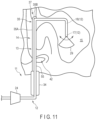
- FIG. 11 is a schematic view showing a state in which the endoscope of the endoscope system shown in FIG. 1 protrudes from the insertion assist device, with the endoscope positioned in an interior portion of the paranasal sinuses (maxillary sinus).
- FIG. 12 is a cross-sectional view showing a step in which the liquid storage shown in FIG. 7 is filled with a liquid by a syringe.
- FIG. 13 is a perspective view showing a grip in a second state in which the grip can be attached to and detached from the sheath in the endoscope system shown in FIG. 1 .
- FIG. 14 is a perspective view showing a grip in a first state in which the grip is fixed to the sheath in the endoscope system of FIG. 1 .
- FIG. 15 is a schematic view showing an insertion assist device and an endoscope of an endoscope system according to a first modification.
- FIG. 16 is a schematic view showing the vicinity of a distal component of an endoscope of an endoscope system according to a second modification.
- the endoscope system 11 includes an endoscope 12 and an insertion assist device 13 for an endoscope configured to guide the endoscope 12 into a sinus of the examinee.
- the endoscope 12 is configured of a so-called soft endoscope which has flexibility.
- the endoscope 12 may be configured of a scanning-type endoscope.
- the insertion assist device 13 is attached to the endoscope 12 .
- the endoscope 12 includes: an insertion portion 16 used for insertion into a nasal cavity 14 , the paranasal sinuses (a maxillary sinus 15 ), etc.; a distal component 17 provided on the vicinity of a distal end of the insertion portion 16 ; a bending portion 18 provided on the proximal side with respect to the distal component 17 and configured to adjust a direction in which the distal component 17 extends; a channel through which a treatment tool that performs a predetermined treatment on the interior of the sinus is passed; an illumination lens 21 ; a plurality of illumination fibers 22 ; a plurality of light-receiving fibers 23 ; a handle 24 for applying various operations (e.g., a bending operation) to the insertion portion 16 ; a controller 26 electrically connected to the insertion portion 16 and the image pickup device 25 by a power line and various signal lines; and a display 27 connected to the controller 26 .
- a central axis C is defined
- the display 27 is configured of a general liquid crystal monitor, and can display an image acquired by the endoscope 12 as an image.
- the bending portion 18 includes a rotatable joint portion and paired wires 28 , 28 extending between the distal component 17 and the handle 24 .
- the handle 24 includes, for example, a dial, and the paired wires 28 , 28 are wound around a rotation shaft of the dial with a pulley or the like interposed therebetween.
- the user can pull the paired wires 28 , 28 by rotating the dial. That is, when one of the pair of wires 28 , 28 is pulled in accordance with the rotation of the dial and the other of the paired wires 28 , 28 is loosened, the distal component 17 is pulled and the bending portion 18 is bent toward either the left or the right. In this manner, the user can make the bending portion 18 bend by operating the dial, thereby changing the direction in which the distal component 17 extends to a desired direction.
- the endoscope 12 has a structure capable of bending in the right-left direction (or the up-down direction).
- the bending direction of the bending portion 18 is an example; the bending portion 18 may be bent in the right-left direction as illustrated by the arrow in FIG. 11 , may be bent to the back side and the front side as illustrated in FIG. 11 , or may be bent in four directions (up, down, right, and left) by providing four wires 28 .
- the illumination fiber 22 is optically connected to a light source provided adjacent to the controller 26 .
- the illumination fiber 22 may emit illumination light to an exterior portion through the illumination lens 21 .
- a plurality of light-receiving fibers 23 are optically connected to the image pickup device 25 .
- a distal end of the light-receiving fiber 23 is exposed to an exterior portion by the light-receiving lens 31 in the vicinity of the distal component 17 . This allows the endoscope 12 to acquire an image through the light-receiving fiber 23 at the distal component 17 .
- the endoscope 12 can acquire an image around a central axis C shown in FIG. 2 through the light-receiving fiber 23 .
- the endoscope 12 includes an image pickup device 25 configured of a CCD, a CMOS, etc.
- the endoscope 12 causes the image pickup device 25 to acquire an image. More specifically, the image pickup device 25 converts light from the light-receiving fiber 23 into an electrical signal and sends the electrical signal to the controller 26 .
- the light-receiving fibers 23 receive return light from the subject and guide the light to the image pickup device 25 .
- the image pickup device 25 sends the light received by light-receiving fibers 23 to the controller 26 as an electrical signal.
- the controller 26 converts the electrical signal into an image, appropriately processes the image, and displays the processed image on the display 27 .
- the controller 26 shown in FIG. 1 is configured by, for example, a general computer.
- the controller 26 is configured of a housing, a circuit substrate 32 built into the housing, a CPU, a ROM, and a RAM mounted on the circuit substrate 32 , and a hard disk drive (HDD) 33 provided separately from the circuit substrate.
- the controller 26 can process an electrical signal corresponding to the image acquired by the image pickup device 25 of the insertion portion 16 for conversion into an image, and display the image (endoscopic image) on the display 27 .
- the insertion assist device 13 includes: a grip 34 which configures a portion gripped by a user's hand; a rail 35 linearly protruding from the grip 34 ; an operation lever 36 provided on the grip 34 ; a liquid storage 39 provided on an interior portion of the grip 34 and configured to store a liquid for treatment; and a sheath 55 provided on an exterior portion of the endoscope 12 .
- the grip 34 has a tubular (cylindrical) shape.
- the grip 34 includes a channel 34 A through the inside of which the endoscope 12 is inserted, and paired open ends 48 , 48 which communicate with the channel 34 A.
- the grip 34 is formed of, for example, a resin material which has flexibility.
- the grip 34 is deformable between a first state S 1 in which the paired open ends 48 and 48 are adjacent to, or abut against each other, and a second state S 2 in which the paired open ends 48 , 48 are separated from each other to allow the endoscope 12 to be inserted into and removed from the channel 34 A. As shown in FIG.
- the grip 34 in the first state S 1 has a tubular shape that surrounds the periphery of the channel 34 A.
- the grip 34 is fixed to the sheath 55 .
- the grip 34 can be attached to and detached from the sheath 55 (endoscope 12 ) through the open ends 48 , as shown in FIG. 13 .
- a holding member 36 B (to be described later) is attached in advance to the outer side of the sheath 55 (endoscope 12 ).
- the grip 34 includes a fixture for fixing the open ends 48 , 48 to each other to maintain the first state S 1 .
- the fixture is configured by, for example, a screw, but is not limited thereto, and may be, for example, a fastener, an engagement structure with a claw, etc.
- the rail 35 is provided so as to be continuous with the grip 34 , and is configured to guide the endoscope 12 .
- the rail 35 includes a linear portion 35 A connected to the grip 34 at one end, an intersecting portion 35 B provided continuously with the other end of the linear portion 35 A, and a field-of-view widening portion 37 provided at at least one of the linear portion 35 A and the intersecting portion 35 B.
- the linear portion 35 A extends linearly in, for example, the same direction as the direction in which the grip 34 extends.
- the rail 35 be formed of, for example, a transparent resin material.
- transparent includes, for example, semi-transparent.
- the rail 35 be configured of a transparent material such as a polycarbonate resin or an acrylic resin. In the case of an acrylic resin, it is preferable, for example, that a polymethyl methacrylate resin (PMMA) be used.
- PMMA polymethyl methacrylate resin
- the field-of-view widening portion 37 is configured of the transparent rail 35 , namely, the entirety of the linear portion 35 A and the entirety of the intersecting portion 35 B.
- the entire rail 35 is formed of a transparent resin material; however, the linear portion 35 A (to be described later) need not be transparent, while it is preferable that at least the intersecting portion 35 B (to be described later) be formed of a transparent resin material.
- the field-of-view widening portion 37 is configured of the entirety of the linear portion 35 A and the entirety of the intersecting portion 35 B.
- the configuration is not limited thereto, and only the intersecting portion 35 B may be formed of a transparent resin material, with the field-of-view widening portion 37 configured of the entirety of the intersecting portion 35 B.
- a distal end portion of the rail 35 is laterally bent to form a substantially “L” shape as a whole.
- the rail 35 is a holding mechanism which holds the endoscope 12 (soft endoscope) in a predetermined shape along the linear portion 35 A.
- a cross-sectional shape of the rail 35 cut along a plane intersecting (orthogonal to) the central axis C of the endoscope 12 is either an arc-like or substantially tabular shape that follows the cross-sectional shape of the columnar endoscope 12 .
- the rail 35 includes: a main body section 43 ; a guide 44 that protrudes from the main body section 43 to form a continuous protrusion along the longitudinal direction of the rail 35 (linear portion 35 A) (the direction of the central axis C of the endoscope 12 ); a slider 45 that can slidably move relative to the guide 44 ; and a fixing portion 46 that fixes the slider 45 and the sheath 55 .
- the guide 44 is provided over the entire length of the rail 35 (the linear portion 35 A and the intersecting portion 35 B) in the longitudinal direction.
- the slider 45 can be fitted onto the outer side of the guide 44 and can slidably move along the guide 44 .
- the slider 45 is formed of, for example, a flexible material, and can be bent along the bend of the rail 35 .
- the fixing portion 46 is configured of, for example, a sheet having adhesiveness on both surfaces, that is, a so-called double-sided tape.
- the slider 45 and the sheath 55 may be integrally formed, with the fixing portion 46 omitted.
- the sheath 55 is formed of a resin material (e.g., rubber) having flexibility in a tubular shape.
- the sheath 55 covers and protects the outer periphery of the endoscope 12 .
- a liquid delivered from the liquid storage 39 is allowed to pass through an interior portion of the sheath 55 .
- the sheath 55 is an example of a tubular member that is provided on an exterior portion of the endoscope 12 .
- the sheath 55 is connected to the liquid storage 39 (via the connecting tube 47 ) at one end, and guides the liquid toward the other end opposite to the one end.
- the sheath 55 includes an opening provided at the other end of the sheath 55 , that is open along the direction (longitudinal direction) in which the endoscope 12 advances and retreats.
- the sheath 55 is an example of a tubular member that is provided on an exterior portion of the endoscope 12 .
- the sheath 55 is connected to a suction device 62 (via the connecting tube 47 ) at one end, and is introduced into a sinus of the examinee at the other end opposite to the one end to remove by suction an undesired substance in the sinus.
- the lever 36 includes a lever main body 36 A and a holding member 36 B against which a lever main body 36 A abuts.
- the lever main body 36 A is formed of a hard resinous material.
- the holding member 36 B is configured in a tubular (cylindrical) shape using, for example, a resin material having a rubber-like elasticity.
- the holding member 36 B is provided to surround part of an outer peripheral surface of the sheath 55 .
- the lever main body 36 A may be molded integrally with the holding member 36 B (2-color molding).
- the grip 34 includes an elongated hole 41 through which a shaft portion of the lever main body 36 A is passed.
- the lever main body 36 A and the sheath 55 are fixed to each other by means of a frictional force using the holding member 36 B, thus causing the sheath 55 (endoscope 12 ) to advance and retreat.
- the mode of fixation between the lever main body 36 A and the sheath 55 is not limited thereto, and the lever main body 36 A may be fixed to the sheath 55 by screwing, etc.
- the lever main body 36 A includes: a head portion 36 AA; a shaft portion 36 AB connected to the head portion 36 AA at one end; and an anti-slip portion 36 AC connected to the other end of the shaft portion 36 AB.
- a width dimension of the head portion 36 AA of the lever main body 36 A is larger than a width dimension of the elongated hole 41 , as viewed in a width direction W intersecting the direction of the central axis C. This prevents the head portion 36 AA from entering the inside of the elongated hole 41 , even when the user presses the head portion 36 AA.
- the width dimension of the anti-slip portion 36 AC is larger than the width dimension of the elongated hole 41 as viewed in the width direction W, to prevent the lever main body 36 A from slipping from the elongated hole 41 .
- the lever 36 can slidably move along the elongated hole 41 .
- the lever 36 is configured to be engageable with the sheath 55 by means of a frictional force of the holding member 36 B.
- the lever 36 By causing the lever 36 to advance and retreat, as shown in FIGS. 8 and 9 , the user can cause the endoscope 12 to protrude from the insertion assist device 13 , or place the endoscope 12 back into the insertion assist device 13 .
- the lever 36 is an example of an operation portion that abuts against an outer peripheral surface of the sheath 55 (tubular member) and causes the sheath 55 to advance and retreat together with the endoscope 12 by means of a frictional force with the outer peripheral surface.
- the liquid storage 39 defines the periphery of a cavity formed in an interior portion of the grip 34 .
- a liquid is stored in an interior portion (cavity portion) of the liquid storage 39 .
- the liquid is configured of, for example, a drug solution for treating rhinitis or the like, but may be another liquid such as physiological saline.
- the liquid storage 39 includes a hard portion 39 A formed of a hard resin material or the like, a protrusion 39 B formed of a material (elastic member) having a rubber-like elasticity, a liquid extraction port 39 C connected to the hard portion 39 A, and a valve that seals the liquid extraction port 39 C.
- the cavity in the liquid storage 39 can be filled with a liquid for treatment or other liquids such as physiological saline using a syringe 40 shown in FIG. 12 .
- the valve When the protrusion 39 B is not pressed, the valve seals the liquid extraction port 39 C. When the protrusion 39 B is depressed by the user's finger, the valve opens, causing the liquid to be delivered toward the sheath 55 via the liquid extraction port 39 C.
- the liquid extraction port 39 C and the sheath 55 are connected by a connecting tube 47 .
- the user introduces the endoscope 12 into the inside of the sheath 55 .
- the sheath 55 is fixed in advance to the slider 45 by the fixing portion 46 .
- the slider 45 is introduced into the guide 44 of the rail 35 to integrate the rail 35 and the sheath 55 .
- the user can introduce the endoscope 12 and the insertion assist device 13 into the nasal cavity 14 of the examinee.
- the user introduces a distal end of the insertion assist device 13 into a nasal cavity 14 of the examinee from an external nostril 42 .
- a distal end portion of the insertion assist device 13 can be advanced toward the back of the nasal cavity 14 , while allowing the endoscope 12 to have a down view of the interior of the nasal cavity 14 .
- a distal end portion (intersecting portion 35 B) of the insertion assist device 13 is shown, together with the nasal cavity 14 , in a field of view 29 of the endoscope 12 .
- a more favorable field of view 29 is ensured if the rail 35 is transparent, since the field of view 29 of the endoscope 12 will not be blocked by the rail 35 . This prevents the user from accidentally hitting the distal end of the rail 35 of the insertion assist device 13 against the inner wall or the like of the nasal cavity 14 .
- the lever 36 is moved (advanced) in the direction of the arrow, as shown in FIGS. 8 and 9 .
- the anti-slip portion 36 AC of the lever 36 deforms the holding member 36 B, thereby increasing the contact area between the holding member 36 B and the sheath 55 .
- a large frictional force is generated between the holding member 36 B and the sheath 55 , allowing the holding member 36 B to grip the sheath 55 .
- the distal component 17 of the endoscope 12 is moved in position from a state of extending along the linear portion 35 A of the rail 35 to a state of extending along the intersecting portion 35 B, and the direction in which the distal component 17 extends is changed by approximately 90°. Thereby, the state shown in FIG. 10 is obtained.
- the user can cause the endoscope 12 to advance into the maxillary sinus 15 by further moving the lever 36 in the direction of the arrow in FIG. 9 , while capturing the entrance of the maxillary sinus 15 (paranasal sinuses) at the front based on the image obtained by the endoscope 12 . As shown in FIG.
- the user can observe the interior of the maxillary sinus 15 by operating the handle 24 to make the endoscope 12 bend using the bending portion 18 , with the distal component 17 of the endoscope 12 reaching the interior of the maxillary sinus 15 .
- the user can perform a treatment on the interior of the maxillary sinus 15 as necessary. On this occasion, various treatments can be performed by using a treatment tool passed through an interior portion of the channel of the endoscope 12 .
- the user can also remove the endoscope 12 from the sheath 55 , and then inject a liquid into the maxillary sinus 15 (paranasal sinuses) via the sheath 55 . Thereby, the liquid can be applied to the inner wall inside the maxillary sinus 15 .
- a branch portion may be provided at the connecting tube 47 , and a proximal end portion of the sheath 55 may be connected to the suction device 62 such as a vacuum pump via the branch portion.
- the user can remove the endoscope 12 from the sheath 55 , and then perform a treatment of removal by suction of pus (an desired substance) gathered in the maxillary sinus 15 (in the sinus of the examinee) by a distal end portion of the sheath 55 . On this occasion, the endoscope 12 is prevented from being contaminated with the pus (undesired substance).
- a withdrawal portion (withdrawal bin) be interposed between the branch portion and the suction device 62 , and an undesired substance is withdrawn into the withdrawal portion.
- the endoscope 12 can be introduced back into the interior portion of the sheath 55 , as necessary.
- the user moves (retracts) the lever 36 in a direction opposite to the direction of the arrow in FIG. 9 , thus placing the endoscope 12 into the insertion assist device 13 .
- the insertion assist device 13 can be safely extracted from the nasal cavity 14 of the examinee, while allowing the endoscope 12 to have a down view of the nasal cavity 14 and the insertion assist device 13 .
- the endoscope 12 is removed prior to the liquid injection, the insertion assist device 13 is extracted from the inside of the nasal cavity 14 , without using the endoscope 12 .
- a liquid is injected into the paranasal sinuses of the examinee using the interior portion of the sheath 55 as a flow path; however, part of the flow path may be formed in an interior portion of the rail 35 .
- the insertion assist device for an endoscope attached to the endoscope 12 includes: a grip 34 including a channel 34 A through the inside of which the endoscope 12 is inserted; an operation portion engaged with the endoscope 12 and configured to move forward and backward relative to the grip 34 to cause the endoscope 12 to advance and retreat; a liquid storage 39 provided on an interior portion of the grip 34 and configured to store a liquid; and a tubular member provided on an interior portion or an exterior portion of the endoscope 12 , connected to the liquid storage 39 at one end, and configured to guide the liquid toward the other end opposite to the one end.
- the endoscope system 11 includes the insertion assist device 13 and the endoscope 12 to be inserted through the channel 34 A of the insertion assist device 13 .
- the insertion assist device for an endoscope includes: a grip 34 attached to the endoscope 12 and including a channel 34 A through the inside of which the endoscope 12 is inserted; an operation portion engaged with the endoscope 12 and configured to move the endoscope 12 forward and backward relative to the grip 34 to cause the endoscope 12 to advance and retreat; and a tubular member provided on an exterior portion of the endoscope 12 to cover the endoscope 12 , connected to a suction device 62 at one end, and introduced into the sinus of the examinee at the other end opposite to the one end to remove by suction an undesired substance in the sinus.
- the tubular member is provided on an exterior portion of the endoscope 12 so as to surround the periphery of the endoscope 12 , and the endoscope 12 can be introduced into and extracted from the tubular member.
- the endoscope 12 can be placed back into the tubular member as necessary. Thereby, it is possible, for example, to confirm the state of completion of the liquid injection using the endoscope 12 .
- the operation portion abuts against an outer peripheral surface of the tubular member, and causes the tubular member to advance and retreat together with the endoscope 12 by means of a frictional force with the outer peripheral surface.
- a grip 34 which includes paired open ends 48 , 48 that communicate with a channel 34 A, is deformable between a first state S 1 in which the paired open ends 48 , 48 are adjacent to, or abut against each other, and a second state S 2 in which the paired open ends 48 , 48 are separated from each other to allow the endoscope 12 to be inserted into and removed from the channel 34 A.
- the grip 34 can be configured with a structure that can be easily attached to and detached from the endoscope 12 .
- the liquid is a drug solution for treatment.
- FIGS. 15 and 16 A modification of the endoscope system 11 will be described with reference to FIGS. 15 and 16 .
- descriptions will be given mainly of configurations different from those of the above-described embodiment, and descriptions and illustrations of configurations common to those of the above-described embodiment will be omitted.
- a first modification of the endoscope system 11 will be described with reference to FIG. 15 .
- a configuration of the insertion assist device 13 is different from that of the above-described embodiment; however, the other configurations are the same as those of the above-described embodiment.
- the insertion assist device 13 includes: a grip 34 which configures a portion gripped by a user's hand; a rail 35 linearly protruding from the grip 34 ; an operation lever 36 provided on the grip 34 ; a liquid storage 39 provided on an interior portion of the grip 34 and configured to store a liquid for treatment; a sheath 55 provided on an exterior portion of the endoscope 12 ; and a second lever 36 provided on the grip 34 and configured to adjust a direction (position) in which the rail 35 extends.
- the rail 35 includes: a linear portion 35 A; a pin 56 provided at one end of the linear portion 35 A; an intersecting portion 35 B provided continuously with the other end of the linear portion 35 A; and a field-of-view widening portion 37 provided at at least one of the linear portion 35 A and the intersecting portion 35 B.
- the linear portion 35 A extends linearly in, for example, the same direction as the direction in which the grip 34 extends.
- the pin 56 is passed through a hole provided on the grip 34 (a boss protruding inside the grip 34 ), and is rotatably supported by the grip 34 . This allows the rail 35 , which is attached to the grip 34 , to be pivoted about the pin 56 by a predetermined angle.
- One end of the linear portion 35 A is connected to a second lever 57 at a further distal position than the pin 56 .
- the second lever 57 is an example of a second operation portion provided on the grip 34 , and is configured to change the position of the rail 35 .
- the rail 35 be formed of, for example, a transparent resin material.
- the entire rail 35 is formed of a transparent resin material; however, the linear portion 35 A (to be described later) need not be transparent, while it is preferable that at least the intersecting portion 35 B (to be described later) be formed of a transparent resin material.
- the user introduces the endoscope 12 into the inside of the sheath 55 , to integrate the endoscope 12 , the rail 35 , and the sheath 55 in advance. In this state, the user can introduce the endoscope 12 and the insertion assist device 13 into the nasal cavity 14 of the examinee.
- the user introduces a distal end of the insertion assist device 13 into a nasal cavity 14 of the examinee from an external nostril 42 .
- a distal end portion of the insertion assist device 13 can be advanced toward the back of the nasal cavity 14 , while allowing the endoscope 12 to have a down view of the interior of the nasal cavity 14 .
- a distal end portion (intersecting portion 35 B) of the insertion assist device 13 is shown, together with the nasal cavity 14 , in a field of view 29 of the endoscope 12 .
- a more favorable field of view 29 is ensured if the rail 35 is transparent, since the field of view 29 of the endoscope 12 will not be blocked by the rail 35 .
- the lever 36 is moved (advanced) in the direction of the arrow, as shown in FIGS. 8 and 9 .
- the state shown in FIG. 10 is obtained.
- the user can cause the endoscope 12 to advance into the maxillary sinus 15 by further moving the lever 36 in the direction of the arrow in FIG. 9 , while capturing the entrance of the maxillary sinus 15 (paranasal sinuses) at the front based on the image obtained by the endoscope 12 .
- the user can finely adjust the position of the rail 35 (the direction in which the rail 35 extends) by operating the second lever 57 .
- various fine adjustments can be performed, for example, to make the endoscope 12 and the sheath 55 face each other with respect to the entrance of the maxillary sinus 15 (paranasal sinuses), or to avoid an obstacle present at the entrance of the maxillary sinus 15 .
- the user can observe the interior of the maxillary sinus 15 by operating the handle 24 to make the endoscope 12 bend using the bending portion 18 , with the distal component 17 of the endoscope 12 reaching the interior of the maxillary sinus 15 .
- the user can also finely adjust the angle of the field of view 29 of the endoscope 12 , by operating the second lever 57 .
- the user can perform a treatment on the interior of the maxillary sinus 15 as necessary. On this occasion, various treatments can be performed by using a treatment tool passed through an interior portion of the channel of the endoscope 12 .
- the user can also remove the endoscope 12 from the sheath 55 , and then inject a liquid into the maxillary sinus 15 (paranasal sinuses) by means of the sheath 55 .
- a suction device such as a vacuum pump, it is possible to perform a treatment of removal by suction of pus gathered inside the maxillary sinus 15 by means of the sheath 55 .
- the user moves (retracts) the lever 36 in a direction opposite to the direction of the arrow in FIG. 9 , thus placing the endoscope 12 into the insertion assist device 13 .
- the insertion assist device 13 can be safely extracted from the nasal cavity 14 of the examinee, while allowing the endoscope 12 to have a down view of the nasal cavity 14 and the insertion assist device 13 .
- the insertion assist device 13 includes: a rail 35 provided so as to be continuous with the grip 34 and configured to guide the endoscope 12 ; and a second operation portion provided on the grip 34 and configured to change the position of the rail 35 .
- a second modification of the endoscope system 11 will be described with reference to FIG. 16 .
- a sheath 55 is not provided on the periphery of the endoscope 12 , unlike the above-described embodiment; however, the other configurations are the same as those of the above-described embodiment.
- the insertion assist device 13 has the same configuration as that of the above-described embodiment except that the sheath 55 is not provided.
- the endoscope 12 includes: an insertion portion 16 used for insertion into a nasal cavity 14 , the paranasal sinuses (a maxillary sinus 15 ), etc.; a distal component 17 provided on the vicinity of a distal end of the insertion portion 16 ; a bending portion 18 provided on the proximal side with respect to the distal component 17 and configured to adjust a direction in which the distal component 17 extends; a channel through which a treatment tool that performs a predetermined treatment on the interior of the sinus is passed; an illumination lens 21 ; a plurality of illumination fibers 22 ; a plurality of light-receiving fibers 23 ; a handle 24 for applying various operations (e.g., a bending operation) to the insertion portion 16 ; a controller 26 electrically connected to the insertion portion 16 and the image pickup device 25 by power lines and various signal lines; and a display 27 connected to the controller 26 .
- various operations e.g., a bending operation
- the holding member 36 B included in the lever 36 of the insertion assist device 13 is configured in a tubular (cylindrical) shape using, for example, a resin material having a rubber-like elasticity.
- the holding member 36 B is provided to surround part of an outer peripheral surface of the endoscope 12 .
- the lever main body 36 A and the endoscope 12 are fixed to each other by means of a frictional force using the holding member 36 B, thus causing the endoscope 12 to advance and retreat.
- the insertion assist device 13 includes a liquid delivery tube 61 passed through an interior portion of the insertion portion 16 .
- the liquid delivery tube 61 is configured of a general flexible tube formed of a resin or the like.
- the liquid delivery tube 61 is provided on an interior portion of the endoscope 12 .
- the liquid delivery tube 61 is connected to a liquid storage 39 at one end.
- the liquid delivery tube 61 can direct the liquid toward the other end (i.e., a distal end of the endoscope) opposite to the one end.
- the endoscope 12 is fixed in advance to a slider 45 with a fixing portion 46 (double-sided tape). Furthermore, the user introduces the slider 45 into the guide 44 of the rail 35 to integrate the rail 35 and the endoscope 12 . In this state, the user can introduce the endoscope 12 and the insertion assist device 13 into the nasal cavity 14 of the examinee.
- the user introduces a distal end of the insertion assist device 13 into a nasal cavity 14 of the examinee from an external nostril 42 .
- a distal end portion of the insertion assist device 13 can be advanced toward the back of the nasal cavity 14 , while allowing the endoscope 12 to have a down view of the interior of the nasal cavity 14 .
- a more favorable field of view 29 is ensured if the rail 35 is transparent, since the field of view 29 of the endoscope 12 will not be blocked by the rail 35 .
- the lever 36 is moved (advanced) in the direction of the arrow, as shown in FIGS. 8 and 9 .
- the anti-slip portion 36 AC of the lever 36 deforms the holding member 36 B, thereby increasing the contact area between the holding member 36 B and the endoscope 12 .
- a large frictional force is generated between the holding member 36 B and the endoscope 12 , allowing the holding member 36 B to grip the endoscope 12 .
- the lever 36 is moved (advanced) in this state, the endoscope 12 is moved (advanced) together with the lever 36 . In this manner, the endoscope 12 protrudes from the rail 35 of the insertion assist device 13 . Thereby, the state shown in FIG. 10 is obtained.
- the user can cause the endoscope 12 to advance into the maxillary sinus 15 by further moving the lever 36 in the direction of the arrow in FIG. 9 , while capturing the entrance of the maxillary sinus 15 (paranasal sinuses) at the front based on the image obtained by the endoscope 12 .
- the user can observe the interior of the maxillary sinus 15 by operating the handle 24 to make the endoscope 12 bend using the bending portion 18 , with the distal component 17 of the endoscope 12 reaching the interior of the maxillary sinus 15 .
- the user can perform a treatment on the interior of the maxillary sinus 15 as necessary. On this occasion, various treatments can be performed by using a treatment tool passed through an interior portion of the channel of the endoscope 12 .
- the liquid delivery tube 61 is provided on the endoscope 12 , removal of the endoscope 12 is not required before the liquid is injected (applied) into the maxillary sinus 15 .
- the user can inject a liquid into the maxillary sinus 15 (paranasal sinuses) or apply a liquid onto the inner wall of the maxillary sinus 15 using the liquid delivery tube 61 built into the endoscope 12 .
- the user moves (retracts) the lever 36 in a direction opposite to the direction of the arrow in FIG. 9 , thus placing the endoscope 12 into the insertion assist device 13 .
- the insertion assist device 13 can be safely extracted from the nasal cavity 14 of the examinee, while allowing the endoscope 12 to have a down view of the nasal cavity 14 and the insertion assist device 13 .
- the tubular member is a liquid delivery tube 61 provided on an interior portion of the endoscope 12 .
- a single endoscope system 11 can be achieved by suitably combining the constituent elements disclosed in the embodiment and its modifications.
Landscapes
- Health & Medical Sciences (AREA)
- Life Sciences & Earth Sciences (AREA)
- Surgery (AREA)
- Heart & Thoracic Surgery (AREA)
- Engineering & Computer Science (AREA)
- Veterinary Medicine (AREA)
- General Health & Medical Sciences (AREA)
- Animal Behavior & Ethology (AREA)
- Public Health (AREA)
- Biomedical Technology (AREA)
- Nuclear Medicine, Radiotherapy & Molecular Imaging (AREA)
- Molecular Biology (AREA)
- Medical Informatics (AREA)
- Radiology & Medical Imaging (AREA)
- Physics & Mathematics (AREA)
- Pathology (AREA)
- Optics & Photonics (AREA)
- Biophysics (AREA)
- Anesthesiology (AREA)
- Hematology (AREA)
- Otolaryngology (AREA)
- Pulmonology (AREA)
- Mechanical Engineering (AREA)
- Dentistry (AREA)
- Oral & Maxillofacial Surgery (AREA)
- Vascular Medicine (AREA)
- Endoscopes (AREA)
- Surgical Instruments (AREA)
- External Artificial Organs (AREA)
Abstract
Description
Claims (19)
Applications Claiming Priority (3)
| Application Number | Priority Date | Filing Date | Title |
|---|---|---|---|
| JP2018051242A JP2021119800A (en) | 2018-03-19 | 2018-03-19 | Insertion aid for endoscope and endoscope system |
| JP2018-051242 | 2018-03-19 | ||
| PCT/JP2018/039492 WO2019181042A1 (en) | 2018-03-19 | 2018-10-24 | Endoscope insertion aid, endoscope system |
Related Parent Applications (1)
| Application Number | Title | Priority Date | Filing Date |
|---|---|---|---|
| PCT/JP2018/039492 Continuation WO2019181042A1 (en) | 2018-03-19 | 2018-10-24 | Endoscope insertion aid, endoscope system |
Publications (2)
| Publication Number | Publication Date |
|---|---|
| US20210000333A1 US20210000333A1 (en) | 2021-01-07 |
| US11986153B2 true US11986153B2 (en) | 2024-05-21 |
Family
ID=67988336
Family Applications (1)
| Application Number | Title | Priority Date | Filing Date |
|---|---|---|---|
| US17/024,777 Active 2040-07-10 US11986153B2 (en) | 2018-03-19 | 2020-09-18 | Insertion assist device for endoscope and endoscope system |
Country Status (3)
| Country | Link |
|---|---|
| US (1) | US11986153B2 (en) |
| JP (1) | JP2021119800A (en) |
| WO (1) | WO2019181042A1 (en) |
Families Citing this family (3)
| Publication number | Priority date | Publication date | Assignee | Title |
|---|---|---|---|---|
| TWI724682B (en) * | 2019-12-11 | 2021-04-11 | 林伯彥 | Bidirectional vascular tube device |
| WO2021209809A1 (en) * | 2020-04-17 | 2021-10-21 | 3Nt Medical Ltd. | Office endoscope |
| JP2025503209A (en) * | 2022-01-27 | 2025-01-30 | クック・メディカル・テクノロジーズ・リミテッド・ライアビリティ・カンパニー | ENDOSCOPE WITH INTERFACE-TYPE ORIENTATION MECHANISM - Patent application |
Citations (29)
| Publication number | Priority date | Publication date | Assignee | Title |
|---|---|---|---|---|
| US5020514A (en) * | 1989-07-19 | 1991-06-04 | Richard Wolf Gmbh | Endoscope for nasal surgery |
| US20010044570A1 (en) * | 2000-05-21 | 2001-11-22 | Asahi Kogaku Kogyo Kabushiki Kaisha | Treating instrument erecting device for use in endoscope |
| US20060063973A1 (en) * | 2004-04-21 | 2006-03-23 | Acclarent, Inc. | Methods and apparatus for treating disorders of the ear, nose and throat |
| US20060095066A1 (en) * | 2004-04-21 | 2006-05-04 | Exploramed Nc1, Inc. | Devices, systems and methods for treating disorders of the ear, nose and throat |
| US20080214890A1 (en) * | 2007-03-01 | 2008-09-04 | Olympus Medical Systems Corporation | Therapeutic method and therapeutic system used with steps for approaching to lesion using overtube |
| US20080228034A1 (en) * | 2007-03-14 | 2008-09-18 | Tetsuya Fujikura | Endoscope apparatus |
| US20080249356A1 (en) * | 2007-04-04 | 2008-10-09 | Olympus Medical Systems Corporation | Therapeutic method and endoscopic system that use overtube |
| JP2008264517A (en) | 2007-04-19 | 2008-11-06 | Olympus Medical Systems Corp | Endoscope operation assistance device |
| US20080275483A1 (en) * | 2004-04-21 | 2008-11-06 | Acclarent, Inc. | Methods and Apparatus for Treating Disorders of the Ear Nose and Throat |
| US20080287961A1 (en) * | 2005-12-01 | 2008-11-20 | Olympus Medical Systems Corp. | Elongated medical member and procedure method using elongated medical member |
| US20090030380A1 (en) * | 2004-12-08 | 2009-01-29 | Xlumena, Inc. | Method and Apparatus for Performing Needle Guided Interventions |
| US20090054727A1 (en) * | 2005-03-31 | 2009-02-26 | Olympus Medical Systems Corp. | Endoscope |
| US20100069712A1 (en) * | 2008-09-12 | 2010-03-18 | Olympus Medical Systems Corp. | Mother-baby endoscope |
| US20100099946A1 (en) * | 2004-04-21 | 2010-04-22 | Acclarent, Inc. | Methods and apparatus for treating disorders of the ear nose and throat |
| US20120071856A1 (en) * | 2010-09-22 | 2012-03-22 | Goldfarb Eric A | Medical Device and Method for Treatment of a Sinus Opening |
| US20120078041A1 (en) * | 2010-05-28 | 2012-03-29 | Olympus Medical Systems Corp. | Endoscope |
| US8241266B2 (en) * | 2007-04-05 | 2012-08-14 | Entellus Medical, Inc. | Apparatus and method for treatment of ethmoids |
| US20130172673A1 (en) * | 2011-12-29 | 2013-07-04 | Cook Medical Technologies Llc | Space-optimized visualization catheter |
| US20150073211A1 (en) * | 2013-09-06 | 2015-03-12 | Covidien Lp | Microwave ablation catheter, handle, and system |
| US20150105818A1 (en) * | 2007-01-16 | 2015-04-16 | Entellus Medical Inc. | Apparatus and method for treatment of sinusitis |
| US20160045100A1 (en) * | 2013-11-21 | 2016-02-18 | Olympus Corporation | Endoscopic treatment device |
| US20160073861A1 (en) * | 2013-12-24 | 2016-03-17 | Olympus Corporation | Sheath for endoscope |
| US20160198934A1 (en) * | 2013-11-14 | 2016-07-14 | Olympus Winter & Ibe Gmbh | Resectoscope with laser fibers |
| WO2016117432A1 (en) | 2015-01-20 | 2016-07-28 | オリンパス株式会社 | Insertion assistance tool and medical device |
| US20160249796A1 (en) * | 2015-02-27 | 2016-09-01 | Olympus Corporation | Treatment method |
| US20160287065A1 (en) * | 2015-03-30 | 2016-10-06 | Acclarent, Inc. | Handle with features to secure a catheter assembly to an endoscope |
| US20160287059A1 (en) * | 2015-03-30 | 2016-10-06 | Acclarent, Inc. | Balloon catheter with image capture and light emission features |
| US20170172389A1 (en) * | 2014-09-05 | 2017-06-22 | Olympus Corporation | Endoscopic treatment instrument, treatment instrument unit, and treatment system |
| WO2017138533A1 (en) | 2016-02-12 | 2017-08-17 | オリンパス株式会社 | Insertion device assembly for paranasal sinuses |
-
2018
- 2018-03-19 JP JP2018051242A patent/JP2021119800A/en active Pending
- 2018-10-24 WO PCT/JP2018/039492 patent/WO2019181042A1/en not_active Ceased
-
2020
- 2020-09-18 US US17/024,777 patent/US11986153B2/en active Active
Patent Citations (39)
| Publication number | Priority date | Publication date | Assignee | Title |
|---|---|---|---|---|
| US5020514A (en) * | 1989-07-19 | 1991-06-04 | Richard Wolf Gmbh | Endoscope for nasal surgery |
| US20010044570A1 (en) * | 2000-05-21 | 2001-11-22 | Asahi Kogaku Kogyo Kabushiki Kaisha | Treating instrument erecting device for use in endoscope |
| US20060063973A1 (en) * | 2004-04-21 | 2006-03-23 | Acclarent, Inc. | Methods and apparatus for treating disorders of the ear, nose and throat |
| US20060095066A1 (en) * | 2004-04-21 | 2006-05-04 | Exploramed Nc1, Inc. | Devices, systems and methods for treating disorders of the ear, nose and throat |
| US20130261388A1 (en) * | 2004-04-21 | 2013-10-03 | Acclarent, Inc. | Methods and apparatus for treating disorders of the ear nose and throat |
| US20100099946A1 (en) * | 2004-04-21 | 2010-04-22 | Acclarent, Inc. | Methods and apparatus for treating disorders of the ear nose and throat |
| US20180125515A1 (en) * | 2004-04-21 | 2018-05-10 | Acclarent, Inc. | Methods and apparatus for treating disorders of the ear nose and throat |
| US20080275483A1 (en) * | 2004-04-21 | 2008-11-06 | Acclarent, Inc. | Methods and Apparatus for Treating Disorders of the Ear Nose and Throat |
| US8328837B2 (en) * | 2004-12-08 | 2012-12-11 | Xlumena, Inc. | Method and apparatus for performing needle guided interventions |
| US20090030380A1 (en) * | 2004-12-08 | 2009-01-29 | Xlumena, Inc. | Method and Apparatus for Performing Needle Guided Interventions |
| US20090054727A1 (en) * | 2005-03-31 | 2009-02-26 | Olympus Medical Systems Corp. | Endoscope |
| US20080287961A1 (en) * | 2005-12-01 | 2008-11-20 | Olympus Medical Systems Corp. | Elongated medical member and procedure method using elongated medical member |
| US9694167B2 (en) * | 2007-01-16 | 2017-07-04 | Entellus Medical Inc. | Apparatus and method for treatment of sinusitis |
| US20150105818A1 (en) * | 2007-01-16 | 2015-04-16 | Entellus Medical Inc. | Apparatus and method for treatment of sinusitis |
| US20080214890A1 (en) * | 2007-03-01 | 2008-09-04 | Olympus Medical Systems Corporation | Therapeutic method and therapeutic system used with steps for approaching to lesion using overtube |
| US20080228034A1 (en) * | 2007-03-14 | 2008-09-18 | Tetsuya Fujikura | Endoscope apparatus |
| US20080249356A1 (en) * | 2007-04-04 | 2008-10-09 | Olympus Medical Systems Corporation | Therapeutic method and endoscopic system that use overtube |
| US8002698B2 (en) * | 2007-04-04 | 2011-08-23 | Olympus Medical Systems Corp. | Therapeutic method that uses overtube |
| US20110301415A1 (en) * | 2007-04-04 | 2011-12-08 | Olympus Medical Systems Corp. | Endoscopic system that uses overtube |
| US8241266B2 (en) * | 2007-04-05 | 2012-08-14 | Entellus Medical, Inc. | Apparatus and method for treatment of ethmoids |
| US20120283625A1 (en) * | 2007-04-05 | 2012-11-08 | Entellus Medical, Inc. | Method for treatment of ethmoids |
| US9278199B2 (en) * | 2007-04-05 | 2016-03-08 | Entellus Medical, Inc. | Method for treatment of ethmoids |
| JP2008264517A (en) | 2007-04-19 | 2008-11-06 | Olympus Medical Systems Corp | Endoscope operation assistance device |
| US20100069712A1 (en) * | 2008-09-12 | 2010-03-18 | Olympus Medical Systems Corp. | Mother-baby endoscope |
| US20120078041A1 (en) * | 2010-05-28 | 2012-03-29 | Olympus Medical Systems Corp. | Endoscope |
| US20120071856A1 (en) * | 2010-09-22 | 2012-03-22 | Goldfarb Eric A | Medical Device and Method for Treatment of a Sinus Opening |
| US20130172673A1 (en) * | 2011-12-29 | 2013-07-04 | Cook Medical Technologies Llc | Space-optimized visualization catheter |
| US20150073211A1 (en) * | 2013-09-06 | 2015-03-12 | Covidien Lp | Microwave ablation catheter, handle, and system |
| US20160198934A1 (en) * | 2013-11-14 | 2016-07-14 | Olympus Winter & Ibe Gmbh | Resectoscope with laser fibers |
| US20160045100A1 (en) * | 2013-11-21 | 2016-02-18 | Olympus Corporation | Endoscopic treatment device |
| US20160073861A1 (en) * | 2013-12-24 | 2016-03-17 | Olympus Corporation | Sheath for endoscope |
| US20170172389A1 (en) * | 2014-09-05 | 2017-06-22 | Olympus Corporation | Endoscopic treatment instrument, treatment instrument unit, and treatment system |
| WO2016117432A1 (en) | 2015-01-20 | 2016-07-28 | オリンパス株式会社 | Insertion assistance tool and medical device |
| US20170311790A1 (en) | 2015-01-20 | 2017-11-02 | Olympus Corporation | Insertion aid and medical device |
| US20160249796A1 (en) * | 2015-02-27 | 2016-09-01 | Olympus Corporation | Treatment method |
| US20160287065A1 (en) * | 2015-03-30 | 2016-10-06 | Acclarent, Inc. | Handle with features to secure a catheter assembly to an endoscope |
| US20160287059A1 (en) * | 2015-03-30 | 2016-10-06 | Acclarent, Inc. | Balloon catheter with image capture and light emission features |
| WO2017138533A1 (en) | 2016-02-12 | 2017-08-17 | オリンパス株式会社 | Insertion device assembly for paranasal sinuses |
| US20170231481A1 (en) * | 2016-02-12 | 2017-08-17 | Olympus Corporation | Insertion device assembly for nasal sinuses |
Non-Patent Citations (2)
| Title |
|---|
| English translation of International Preliminary Report on Patentability dated Oct. 1, 2020 together with the Written Opinion issued in International Application No. PCT/JP2018/039492. |
| International Search Report dated Jan. 29, 2019 received in International Application No. PCT/JP2018/039492, together with an English-language translation. |
Also Published As
| Publication number | Publication date |
|---|---|
| US20210000333A1 (en) | 2021-01-07 |
| WO2019181042A1 (en) | 2019-09-26 |
| JP2021119800A (en) | 2021-08-19 |
Similar Documents
| Publication | Publication Date | Title |
|---|---|---|
| US11395579B2 (en) | Portable endoscope with disposable steerable cannula | |
| US20230320573A1 (en) | Portable endoscope with steerable cannula | |
| US20230320574A1 (en) | Coaxial micro-endoscope | |
| US10524636B2 (en) | Handheld surgical endoscope | |
| US12075973B2 (en) | Medical systems, devices, and related methods | |
| US10278563B2 (en) | Handheld surgical endoscope with detachable cannula | |
| US11986153B2 (en) | Insertion assist device for endoscope and endoscope system | |
| CN103491854B (en) | Multicomponent cover for many cameras endoscope | |
| CA2572576C (en) | Endoscope with a guide-wire for treatment instruments | |
| US8075474B2 (en) | Endoscope system and medical instrument | |
| JP4163438B2 (en) | Endoscope | |
| JP6432091B2 (en) | Endoscopic treatment instrument drive control device | |
| JP6375457B2 (en) | Insertion device assembly for the sinuses | |
| JP4914891B2 (en) | Endoscopic treatment system | |
| US7691054B2 (en) | Endoscope system, treatment instrument cartridge, and storage case | |
| US20180160885A1 (en) | Endoscopy based medical devices, methods, and innovations | |
| JP3776527B2 (en) | Endoscope | |
| US10159401B2 (en) | Assist device and endoscopic system | |
| CN121443198A (en) | Medical systems, devices and related methods | |
| WO2019181039A1 (en) | Endoscope system and guide member |
Legal Events
| Date | Code | Title | Description |
|---|---|---|---|
| AS | Assignment |
Owner name: OLYMPUS CORPORATION, JAPAN Free format text: ASSIGNMENT OF ASSIGNORS INTEREST;ASSIGNORS:SAKAI, YUJI;TAKEYAMA, TETSUHIDE;SIGNING DATES FROM 20200904 TO 20200908;REEL/FRAME:053811/0001 |
|
| FEPP | Fee payment procedure |
Free format text: ENTITY STATUS SET TO UNDISCOUNTED (ORIGINAL EVENT CODE: BIG.); ENTITY STATUS OF PATENT OWNER: LARGE ENTITY |
|
| STPP | Information on status: patent application and granting procedure in general |
Free format text: APPLICATION DISPATCHED FROM PREEXAM, NOT YET DOCKETED |
|
| STPP | Information on status: patent application and granting procedure in general |
Free format text: DOCKETED NEW CASE - READY FOR EXAMINATION |
|
| STPP | Information on status: patent application and granting procedure in general |
Free format text: NON FINAL ACTION MAILED |
|
| STPP | Information on status: patent application and granting procedure in general |
Free format text: NON FINAL ACTION MAILED |
|
| STPP | Information on status: patent application and granting procedure in general |
Free format text: RESPONSE TO NON-FINAL OFFICE ACTION ENTERED AND FORWARDED TO EXAMINER |
|
| STPP | Information on status: patent application and granting procedure in general |
Free format text: FINAL REJECTION MAILED |
|
| STPP | Information on status: patent application and granting procedure in general |
Free format text: RESPONSE AFTER FINAL ACTION FORWARDED TO EXAMINER |
|
| STPP | Information on status: patent application and granting procedure in general |
Free format text: NOTICE OF ALLOWANCE MAILED -- APPLICATION RECEIVED IN OFFICE OF PUBLICATIONS |
|
| STPP | Information on status: patent application and granting procedure in general |
Free format text: PUBLICATIONS -- ISSUE FEE PAYMENT VERIFIED |
|
| STCF | Information on status: patent grant |
Free format text: PATENTED CASE |