US11986106B2 - Adaptable product storage and extraction tray - Google Patents
Adaptable product storage and extraction tray Download PDFInfo
- Publication number
- US11986106B2 US11986106B2 US17/993,406 US202217993406A US11986106B2 US 11986106 B2 US11986106 B2 US 11986106B2 US 202217993406 A US202217993406 A US 202217993406A US 11986106 B2 US11986106 B2 US 11986106B2
- Authority
- US
- United States
- Prior art keywords
- longitudinal
- support plates
- tray
- extractor
- dividing
- Prior art date
- Legal status (The legal status is an assumption and is not a legal conclusion. Google has not performed a legal analysis and makes no representation as to the accuracy of the status listed.)
- Active
Links
- 238000000605 extraction Methods 0.000 title claims abstract description 10
- 238000005192 partition Methods 0.000 claims abstract description 84
- 230000000712 assembly Effects 0.000 claims abstract description 56
- 238000000429 assembly Methods 0.000 claims abstract description 56
- 238000006073 displacement reaction Methods 0.000 claims abstract description 16
- 239000000047 product Substances 0.000 claims description 48
- 230000014759 maintenance of location Effects 0.000 claims description 16
- 230000000295 complement effect Effects 0.000 claims description 5
- 239000013589 supplement Substances 0.000 claims description 3
- 230000006978 adaptation Effects 0.000 description 4
- 238000000926 separation method Methods 0.000 description 3
- XAGFODPZIPBFFR-UHFFFAOYSA-N aluminium Chemical compound [Al] XAGFODPZIPBFFR-UHFFFAOYSA-N 0.000 description 1
- 229910052782 aluminium Inorganic materials 0.000 description 1
- 239000004411 aluminium Substances 0.000 description 1
- 238000005452 bending Methods 0.000 description 1
- 230000000903 blocking effect Effects 0.000 description 1
- 230000003750 conditioning effect Effects 0.000 description 1
- 230000003247 decreasing effect Effects 0.000 description 1
- 238000009434 installation Methods 0.000 description 1
- 238000004519 manufacturing process Methods 0.000 description 1
- 230000002787 reinforcement Effects 0.000 description 1
- 230000000717 retained effect Effects 0.000 description 1
- 230000000007 visual effect Effects 0.000 description 1
- 239000002699 waste material Substances 0.000 description 1
Images


Classifications
-
- A—HUMAN NECESSITIES
- A47—FURNITURE; DOMESTIC ARTICLES OR APPLIANCES; COFFEE MILLS; SPICE MILLS; SUCTION CLEANERS IN GENERAL
- A47B—TABLES; DESKS; OFFICE FURNITURE; CABINETS; DRAWERS; GENERAL DETAILS OF FURNITURE
- A47B57/00—Cabinets, racks or shelf units, characterised by features for adjusting shelves or partitions
- A47B57/58—Cabinets, racks or shelf units, characterised by features for adjusting shelves or partitions with means for adjusting partitions horizontally
- A47B57/583—Cabinets, racks or shelf units, characterised by features for adjusting shelves or partitions with means for adjusting partitions horizontally by sliding
- A47B57/585—Cabinets, racks or shelf units, characterised by features for adjusting shelves or partitions with means for adjusting partitions horizontally by sliding with connection means slidable in a rail
-
- A—HUMAN NECESSITIES
- A47—FURNITURE; DOMESTIC ARTICLES OR APPLIANCES; COFFEE MILLS; SPICE MILLS; SUCTION CLEANERS IN GENERAL
- A47F—SPECIAL FURNITURE, FITTINGS, OR ACCESSORIES FOR SHOPS, STOREHOUSES, BARS, RESTAURANTS OR THE LIKE; PAYING COUNTERS
- A47F1/00—Racks for dispensing merchandise; Containers for dispensing merchandise
- A47F1/04—Racks or containers with arrangements for dispensing articles, e.g. by means of gravity or springs
- A47F1/12—Racks or containers with arrangements for dispensing articles, e.g. by means of gravity or springs dispensing from the side of an approximately horizontal stack
- A47F1/125—Racks or containers with arrangements for dispensing articles, e.g. by means of gravity or springs dispensing from the side of an approximately horizontal stack with an article-pushing device
-
- A—HUMAN NECESSITIES
- A47—FURNITURE; DOMESTIC ARTICLES OR APPLIANCES; COFFEE MILLS; SPICE MILLS; SUCTION CLEANERS IN GENERAL
- A47F—SPECIAL FURNITURE, FITTINGS, OR ACCESSORIES FOR SHOPS, STOREHOUSES, BARS, RESTAURANTS OR THE LIKE; PAYING COUNTERS
- A47F5/00—Show stands, hangers, or shelves characterised by their constructional features
- A47F5/0043—Show shelves
- A47F5/005—Partitions therefore
-
- G—PHYSICS
- G07—CHECKING-DEVICES
- G07F—COIN-FREED OR LIKE APPARATUS
- G07F11/00—Coin-freed apparatus for dispensing, or the like, discrete articles
- G07F11/007—Coin-freed apparatus for dispensing, or the like, discrete articles wherein the storage and dispensing mechanism are configurable in relation to the physical or geometrical properties of the articles to be stored or dispensed
-
- G—PHYSICS
- G07—CHECKING-DEVICES
- G07F—COIN-FREED OR LIKE APPARATUS
- G07F11/00—Coin-freed apparatus for dispensing, or the like, discrete articles
- G07F11/02—Coin-freed apparatus for dispensing, or the like, discrete articles from non-movable magazines
- G07F11/04—Coin-freed apparatus for dispensing, or the like, discrete articles from non-movable magazines in which magazines the articles are stored one vertically above the other
- G07F11/16—Delivery means
- G07F11/26—Endless bands
-
- G—PHYSICS
- G07—CHECKING-DEVICES
- G07F—COIN-FREED OR LIKE APPARATUS
- G07F11/00—Coin-freed apparatus for dispensing, or the like, discrete articles
- G07F11/02—Coin-freed apparatus for dispensing, or the like, discrete articles from non-movable magazines
- G07F11/38—Coin-freed apparatus for dispensing, or the like, discrete articles from non-movable magazines in which the magazines are horizontal
- G07F11/42—Coin-freed apparatus for dispensing, or the like, discrete articles from non-movable magazines in which the magazines are horizontal the articles being delivered by motor-driven means
-
- A—HUMAN NECESSITIES
- A47—FURNITURE; DOMESTIC ARTICLES OR APPLIANCES; COFFEE MILLS; SPICE MILLS; SUCTION CLEANERS IN GENERAL
- A47F—SPECIAL FURNITURE, FITTINGS, OR ACCESSORIES FOR SHOPS, STOREHOUSES, BARS, RESTAURANTS OR THE LIKE; PAYING COUNTERS
- A47F1/00—Racks for dispensing merchandise; Containers for dispensing merchandise
- A47F1/04—Racks or containers with arrangements for dispensing articles, e.g. by means of gravity or springs
- A47F1/12—Racks or containers with arrangements for dispensing articles, e.g. by means of gravity or springs dispensing from the side of an approximately horizontal stack
-
- A—HUMAN NECESSITIES
- A47—FURNITURE; DOMESTIC ARTICLES OR APPLIANCES; COFFEE MILLS; SPICE MILLS; SUCTION CLEANERS IN GENERAL
- A47F—SPECIAL FURNITURE, FITTINGS, OR ACCESSORIES FOR SHOPS, STOREHOUSES, BARS, RESTAURANTS OR THE LIKE; PAYING COUNTERS
- A47F5/00—Show stands, hangers, or shelves characterised by their constructional features
- A47F5/10—Adjustable or foldable or dismountable display stands
- A47F5/105—Adjustable partition panels for displaying articles
Definitions
- the present invention relates to an adaptable product storage and extraction tray, intended for being installed in a vending machine, where the tray is provided with laterally movable dividing partitions defining compartments, extractor assemblies and support plates which are also laterally movable, which allow the reconfiguration of the width of the compartments.
- the widths of the compartments can be modified in a short time, in a very simple manner and eliminating the need to take out all the products stored in the different compartments to make these adjustments.
- products are often stored in horizontal trays which are usually divided into channels or compartments housing one and the same type of product and extractors which push the products towards a product dispensing area.
- the motors of the spirals are fixed in the rear part of the tray, such that the flexibility they offer is to place double or single channels or to buy entire trays with a larger or smaller number of motors in the rear part, to adapt the machines to the products.
- the extractors and the motors constitute a single component which can be placed in the tray in a number of positions, like the partitions, positioning same in grooves made in the tray for this purpose, such that the adaptation in width is possible with the relocation of the different elements.
- performing this relocation of elements also requires removing the products from the channels which have to be modified, in many cases having to empty the tray of all the products.
- this system has the conditioning fact that the grooves for locating the partitions and extractors do not have a constant passage.
- trays which adapt the width of their compartments by means of rail systems, such as patent document EP3076828A1, for example, which relates to a tray where the partitions and the extractors are attached in a manner so as to be linked to a front rail and another, rear rail.
- patent document EP3076828A1 which relates to a tray where the partitions and the extractors are attached in a manner so as to be linked to a front rail and another, rear rail.
- cavities at the base of the tray.
- Said trays do not include supports on which the products can rest, and said products easily engage with the parts of the tray. Furthermore, by having to fix the different elements in cavities intended for such purpose arranged at the base, flexibility is limited and a continuous adaptation of the width of the channel is not achieved in a rapid and simple manner. Additionally, the rigidity conferred by said tray is not suitable for products that weigh a lot.
- the present invention relates to a product storage and extraction tray, intended for being installed in a vending machine.
- the tray comprises a quadrangular base provided with an upper surface and with lateral sides, a rear side and a front side, a front profile linked to the front side, lateral walls and a rear wall starting in the upper part from the corresponding sides of the base, with the front side of the tray being open for dispensing the products.
- the tray also comprises dividing partitions arranged perpendicularly with respect to the upper surface of the base and distributed parallel to one another, longitudinal parallel compartments defined between the dividing partitions and between the endmost dividing partitions and the lateral walls, and limited by the rear wall and in the lower part by the upper surface of the base, longitudinal extractor assemblies arranged in each compartment which store and push the products towards the front side of the base for the dispensing thereof and longitudinal support plates, located on both sides of each extractor assembly, intended for partially supporting the products transported by the extractor assemblies and where the support plates delimit the width of each compartment.
- the extractor assemblies and the dividing partitions are linked to the front profile with the possibility of transverse displacement and the support plates can be linked to the front profile with the possibility of transverse displacement.
- the support plates can be transversely coupled to one another and are removable so as to allow the displacement of the extractor assemblies and dividing partitions and modify the width of the compartments.
- the tray comprises at least one movable retaining element, which regulates the position of the support plates, the extractor assembly or the dividing partition that is located the closest to a lateral wall, with respect to the lateral wall between a retention position in which it keeps the support plates coupled to one another and in which the support plates, the extractor assembly or the dividing partition that is the closest to the lateral wall maintains a clearance with the lateral wall, and a release position in which it releases the support plates for the removal thereof.
- the support plates can be extracted from one of the compartments and introduced into another compartment, thereby changing the width of the compartments.
- the dividing partitions and the extractor assemblies are also laterally displaced so as to adjust to the width of the compartment, as well as the rest of the support plates.
- the width of the compartment is determined by the number of support plates. Once the width of the compartments is determined, the retaining element is placed in the retention position, where it blocks the displacement of the mentioned slidable elements of the tray, which are the support plates, the extractor assemblies and the dividing partitions, and keeps them laterally compacted with one another.
- the configuration of the tray is applicable to different widths of machines.
- the proposed tray intends to provide the greatest flexibility when reconfiguring trays, allowing both dividing partitions and extractor assemblies to be able to move laterally without having to be taken out of the trays of the machine for reconfiguration, with the waste of time that this represents.
- the support plates are also transversely displaced.
- the front profile can be made of aluminium and can comprise an outer surface, intended for facing the dispensing area, and a preferably ribbed inner surface.
- the front side of the base is linked to said ribbed area, with a segment of the profile above the upper area of the tray and another segment of the ribbed surface in the lower area which serves to be gripped by a user and move the entire tray, since the base is fixed to the front profile.
- the outer surface serves to house identification labels and displace them laterally without taking them out of their location.
- One of the functions of the support plates is to form a longitudinal support where the products partially rest to release the profile which imparts structure to the tray in the front part and to form a continuous surface over which they slip as they are pushed by the driving action of the extractor assembly, facilitating the outlet thereof.
- the support plates protrude from the uppermost part of the front profile.
- the plates have a fixed passage, where they can be laterally stacked as many times needed, increasing or decreasing the separation in passages of a predefined width, for example, of 5 mm.
- the support plates can comprise on one of their faces a recess and on another one of their faces a projection intended for being housed in the recess of another contiguous support plate. In this way, they are all designed to fit with one another such that they are captured by a system of projections and recesses which laterally fit with one another.
- both the extractor assemblies and the dividing partitions can have a fitting surface on both sides, which are complementary to the recesses and projections of the support plates, and which allow the lateral stacking of the dividing partitions, the extractor assemblies and the support plates in a retention situation.
- These fitting surfaces are also recesses and projections identical to those of the support plates, which are arranged on the outermost faces of the extractor assemblies and of the dividing partitions.
- the support plates would be configured to laterally fit with one another and with the extractors and the dividing partitions, in a non-permanent manner. In this way, the support plates fill the entire space between the dividing partitions and the extractor assemblies such that there is no space whatsoever where the corners of bags can be caught.
- the tray is therefore always filled with the dividing partitions, the support plates and the extractor assemblies until completing the entire width thereof. Furthermore, the reconfiguration of the separating spaces between the different components forming an extraction channel is entirely visual since each support plate has a predefined and therefore known thickness, and simply counting the number of support plates intercalated in each compartment is sufficient for delimiting the suitable separation.
- the lateral stacking of all the support plates confers robustness to the assembly to maintain the perpendicular arrangement of the dividing partitions and to enable supporting weight on the tray. It should be pointed out that this type of vending machine must be robust against vandalism, so it is very important for the partitions to maintain the perpendicular arrangement with respect to the tray, because they carry the product retention systems.
- the product retention systems can be peg type or strip type stops, depending on the type of extractor assembly, which prevent the products from falling off the tray.
- the retaining element is in charge of laterally compacting the movable elements.
- the retaining element can be a wedge assembly, a part housing a spring therein or any element that serves to laterally compact and loosen the support plates.
- the support element preferably comprises a bushing partially housed in at least one pass-through cavity made in the support plates, in the extractor assemblies or in the dividing partition and an attachment element partially housed in the bushing.
- the bushing is housed in the part closest to the lateral wall, which can be an extractor assembly, a dividing partition or a support plate.
- the retaining elements are preferably two per tray, such that they must have two pass-through cavities per support plate, extractor assembly and dividing panel.
- the front profile on which the dividing partitions and the extractor assemblies laterally slide and which support the support plates furthermore performs tray reinforcement functions helping to reach bending strengths which allow a single tray to be produced regardless of the weight to be supported, even supporting weights of up to 60 kg, standardising production. Additionally, this tray can subsequently be reconfigured for heavy products, without adding anything, without having to modify heights and dispensing with a useful space for the products for sale. In this way, the products to be sold in each machine will not be limited by the size of the compartments thereof, but rather the compartments will be adapted to the products to be offered.
- the dividing partitions and the extractor assemblies are additionally linked in a slidable manner to the rear wall at the ends opposite those linked to the front profile.
- the extractor assemblies and the dividing partitions thereby slide in a guided manner at their two ends, achieving a controlled displacement movement.
- the dividing partitions and the extractor assemblies are inserted in a rib or channel of the front profile such that the lower part of the dividing partitions and the extractor assemblies have a design which copies the inverse form of the front profile, said parts fitting tightly with one another.
- This design allows the lateral displacement of the dividing partitions and the extractor assemblies while at the same time assuring the perpendicular arrangement thereof with respect to the base of the trays without the need for the help of third parts, so the reconfiguration of partitions and channels again requires less labour.
- the tray can comprise a height supplement that can be coupled to the dividing partitions, where one or more can be placed above the other one consecutively as many times needed, whereby obtaining partitions of different heights without the need to arrange as many different references and allowing an adjustment in height of the compartments.
- FIG. 1 shows a perspective view of a tray.
- FIG. 2 shows an exploded view of two retaining elements and support plates.
- FIG. 3 shows a detailed view of the retaining element in a retention position.
- FIG. 4 shows a detailed view of the retaining element in a release position.
- FIG. 5 shows a perspective view of the base, the front profile, the lateral walls and the rear wall.
- FIG. 6 shows a cross-sectional view of FIG. 5 .
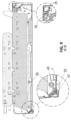
- FIG. 7 shows an elevational view of the tray.
- FIG. 8 shows a view of section A-A of FIG. 7 , where an extractor assembly can be seen.
- FIG. 9 shows a view of section B-B of FIG. 7 , where a dividing partition can be seen.
- FIG. 10 shows a view of section C-C of FIG. 7 , where a support plate can be seen.
- FIG. 11 shows a profile view of a dividing partition.
- FIG. 12 shows a perspective view of a support plate.
- FIG. 13 shows a perspective view of an extractor assembly.
- FIG. 1 shows a perspective view of a tray according to the present invention, where there can be seen a quadrangular base ( 1 ) provided with an upper surface ( 2 ) and with lateral sides ( 3 ), a rear side ( 4 ) and a front side ( 5 ), which cannot be seen in the figure.
- a quadrangular base ( 1 ) provided with an upper surface ( 2 ) and with lateral sides ( 3 ), a rear side ( 4 ) and a front side ( 5 ), which cannot be seen in the figure.
- the tray has a front profile ( 20 ) linked to the front side ( 5 ) of the tray ( 1 ), lateral walls ( 6 ) and a rear wall ( 7 ) starting in the upper part from the corresponding sides of the base ( 1 ), with the front side ( 5 ) of the tray being open for dispensing the products.
- the tray of the embodiment shown comprises 5 compartments ( 9 ).
- the tray comprises several longitudinal extractor assemblies ( 10 ) arranged in each compartment ( 9 ) which store and push the products towards the front profile ( 20 ) for the dispensing thereof.
- the extractor assemblies ( 10 ) are centred in each compartment ( 9 ).
- support plates ( 12 ) located on both sides of each of the extractor assemblies ( 10 ) of each compartment ( 9 ), which are intended for supporting the lateralmost areas of the products transported by the extractor assemblies ( 10 ) and delimiting the width of each compartment ( 9 ).
- the extractor assemblies ( 10 ) and the dividing partitions ( 8 ) are linked to the front profile ( 20 ) and with the possibility of transverse displacement.
- the support plates ( 12 ) can be removably linked to the front profile ( 20 ) and likewise have the possibility of transverse displacement.
- the width of the compartments ( 9 ) is adapted by means of the transverse displacement of the mentioned elements.
- the support plates ( 12 ) can be transversely coupled, and are removable, i.e., they can be easily separated from the front profile ( 20 ), with the support plates ( 12 ) being interchangeable between compartments ( 9 ).
- the displacement of the support plates ( 12 ), the extractor assemblies ( 10 ) and dividing partitions ( 8 ) is allowed, and the width of the compartments ( 9 ) is modified, adapting them to the width of the products supported by each extractor assembly ( 10 ).
- the tray comprises at least one movable retaining element ( 13 ), which cannot be seen in the figure, which regulates the position of the support plates ( 12 ) closest to the lateral wall ( 6 ) and which is located next to a lateral wall ( 6 ).
- an extractor assembly ( 10 ) or a dividing partition ( 8 ) can be the element closest to the lateral wall ( 6 ), such that the retaining element ( 13 ) would regulate the position of the extractor assembly ( 10 ) or of the dividing partition ( 8 ) with respect to the lateral wall ( 6 ).
- the retaining element ( 13 ) When the retaining element ( 13 ) is in a retention position, it blocks the movement of all the elements, keeping them at a distance from the lateral wall ( 6 ). When the retaining element ( 13 ) is in a release position, it stops exerting force against the movable elements such that these can be displaced on the front profile ( 20 ) and the support plates ( 12 ) can be extracted if the width of the compartments ( 9 ) needs to be modified.
- FIG. 2 shows an exploded view of two retaining elements ( 13 ) and support plates ( 12 ) stacked which are provided with two plate pass-through cavities ( 14 ), according to the present invention.
- the retaining element ( 13 ) is provided with a bushing ( 15 ) configured for being housed partially in at least the plate pass-through cavity ( 14 ) and with an attachment element ( 16 ) intended for being housed partially in the bushing ( 15 ).
- the bushing ( 15 ) in turn comprises a central cavity ( 37 ) and a threaded cavity ( 17 ) extending from the central cavity ( 37 ).
- the attachment element ( 16 ) comprises a threaded rod ( 18 ) configured for being housed and screwed in the threaded cavity ( 17 ) and a head ( 19 ) at one end of the rod ( 18 ) configured for being housed in a release situation in the central cavity ( 37 ) of the bushing ( 15 ) or for contacting the lateral wall ( 6 ) in a retention situation.
- the surface which defines the plate pass-through cavities ( 14 ) comprises a pair of opposing grooves ( 46 ) and the bushing ( 15 ) comprises ribs ( 47 ) which, in an assembly situation, fit in said grooves ( 46 ), preventing the bushing from rotating with respect to the cavity ( 14 ).
- the grooves ( 46 ) are present on all the surfaces limiting the pass-through cavities ( 14 , 34 , 35 ).
- FIG. 3 shows a detailed view of the retaining element ( 13 ) in a retention position in which it keeps the support plates ( 12 ) coupled to one another and spaced from the lateral wall ( 6 ).
- FIG. 4 shows a detailed view of the retaining element ( 13 ) in a release position in which it releases the support plates ( 12 ) for the removal thereof and, as pressure is no longer exerted on the support plates ( 12 ), allows the displacement of same, as well as of the extractor assemblies ( 10 ) and the dividing partitions ( 8 ) with respect to the front profile ( 20 ).
- the attachment element ( 16 ) is completely introduced in the bushing ( 15 ), as the rod ( 18 ) is screwed in the threaded cavity ( 17 ), and a space is generated with respect to the lateral wall ( 6 ), such that the support plates ( 12 ), the extractor assemblies ( 10 ) and the dividing partitions ( 8 ) can be moved. In this situation, the support plates ( 12 ) can be extracted. In contrast, when the rod ( 18 ) is unscrewed from the threaded cavity ( 17 ), the attachment element ( 16 ) moves away from the bushing ( 15 ) and contacts the lateral wall ( 6 ), keeping the support plates ( 12 ) compacted.
- the retaining element ( 13 ) prevents the transverse displacement movement of the support plates ( 12 ), the extractor assemblies ( 10 ) and the dividing partitions ( 8 ) with respect to the front profile ( 20 ) and, accordingly, the removal of the support plates ( 12 ).
- the lateral wall ( 6 ) is provided with a pass-through access borehole ( 38 ) of a smaller size than the head ( 19 ) of the attachment element ( 16 ), which is preferably a screw and allows same to be accessed and activated, for example, with a screwdriver.
- the bushing ( 15 ) is housed in the plate pass-through cavity ( 14 ) of two support plates ( 12 ) and has a cone shape which prevents it from slipping and being displaced from its predetermined position.
- the bushing ( 15 ) is housed in the plate pass-through cavities ( 14 ) although they can alternatively be housed in an extractor pass-through cavity ( 34 ) or in a partition pass-through cavity ( 35 ), which cannot be seen in the figure, depending on which part of the tray is located closest to the lateral wall ( 6 ).
- FIG. 5 shows a perspective view of the base ( 1 ) of the tray, the lateral walls ( 6 ) and the rear wall ( 7 ) extending from the rear side ( 4 ) of the base ( 1 ).
- the profile ( 20 ) attached to the front side ( 5 ) of the base ( 1 ) is likewise shown.
- the extractor assemblies ( 10 ), the dividing partitions ( 8 ) and the support plates ( 12 ), which cannot be seen in the figure, are supported on the upper surface ( 2 ) of the base ( 1 ).
- FIG. 6 shows a cross-sectional view of FIG. 5 , in which it can be seen that the front profile ( 20 ) is provided with tabs ( 36 ) on its outer surface intended for retaining a product label.
- a lower area ( 43 ) of the front profile ( 20 ) which, in the assembly situation, is located below the base ( 1 ) and serves to enable the user to grip the front profile ( 20 ) with one hand and exert force on it to extract the tray.
- This lower area ( 43 ) of the front profile ( 20 ) also serves as support for the base ( 1 ).
- the front profile ( 20 ) also comprises an upper area ( 44 ), which is located above the tray ( 1 ) in an assembly situation.
- the front profile ( 20 ) comprises at least two channels on its inner surface, a first longitudinal channel ( 22 ) which serves to fit the extractor assemblies ( 10 ) therein in a slidable manner and a second longitudinal channel ( 42 ) which houses the front side ( 5 ) of the base ( 1 ) and one end of the dividing partition ( 8 ), not shown in the figure.
- Said second longitudinal channel ( 42 ) and the first longitudinal channel ( 22 ) are separated by a dividing rib ( 45 ).
- FIG. 7 shows an elevational view of a tray, in which the longitudinal parallel compartments ( 9 ) defined between the dividing partitions ( 8 ) and between the endmost dividing partitions ( 8 ) and the lateral walls ( 6 ), and limited by the rear wall ( 7 ) and in the lower part by the upper surface ( 2 ) of the base ( 1 ) can be seen in greater detail.
- FIG. 8 shows a view of section A-A of FIG. 7 , where an extractor assembly ( 10 ) can be seen in section.
- the extractor assembly ( 10 ) comprises a first extractor protuberance ( 24 ) at its end attached to the front profile ( 20 ), which is housed in the first longitudinal channel ( 22 ) of the front profile ( 20 ).
- the extractor assemblies ( 10 ) are additionally linked to the rear wall ( 7 ) at the ends opposite those linked to the front profile ( 20 ).
- the rear wall ( 7 ) comprises a longitudinal rear channel ( 25 ), which cannot be seen in the figure, and the extractor assembly comprises a second extractor protuberance ( 27 ), housed in the longitudinal rear channel ( 25 ) such that the displacement is performed in a more controlled and precise manner since the extractor assemblies ( 10 ) are attached in the rear part and in the front part.
- the extractor assemblies ( 10 ) comprise two extractor pass-through cavities ( 34 ) configured for partially housing the retaining element ( 13 ).
- FIG. 9 shows a view of section B-B of FIG. 7 , where a dividing partition ( 8 ) can be seen in section.
- the dividing partition ( 8 ) rests on the upper surface ( 2 ) of the base ( 1 ) and comprises a first dividing protuberance ( 23 ) at its end, which is housed in the second longitudinal channel ( 42 ) and fits between the rib ( 45 ) and the base ( 1 ) of the front profile ( 20 ), which can be seen in greater detail in FIG. 6 .
- the dividing partitions ( 8 ) are additionally linked to the rear wall ( 7 ) at the ends opposite those linked to the front profile ( 20 ).
- the dividing partition ( 8 ) shown comprises two partition pass-through cavities ( 35 ) configured for partially housing the retaining element ( 13 ).
- FIG. 10 shows a view of section C-C of FIG. 7 , where a support plate ( 12 ) provided with two plate pass-through cavities ( 14 ) for housing the retaining assembly ( 13 ) can be seen in section.
- the end of the support plates ( 12 ) rests on the front profile ( 20 ) but is not permanently retained, so that the extraction of the support plates ( 12 ) is simpler.
- the end is provided with a stop ( 30 ), which partially fits with the inner surface of the front profile ( 20 ) in an assembly position and prevents the longitudinal movement of the support plates ( 12 ) in the direction towards the front profile ( 20 ).
- the length of the support plates ( 12 ) is less than the length of the extractor assemblies ( 10 ) so as to facilitate their handling and extraction.
- FIG. 11 shows a profile view of a dividing partition ( 8 ), where the dividing partition ( 8 ) comprises a lower edge ( 31 ) facing the base ( 1 ) and a free upper edge ( 32 ), and the tray comprises a height supplement ( 33 ) that can be coupled to the upper edge ( 32 ).
- the dividing partitions ( 8 ) comprise a fitting surface ( 48 ) on both sides which are complementary to the recesses ( 28 ) and projections ( 29 ) of the support plates ( 12 ) and which allow the lateral stacking of the dividing partitions ( 8 ), the extractor assemblies ( 10 ) and the support plates ( 12 ) in a retention situation.
- This fitting surface ( 48 ) is a projection on one of the sides of the dividing partition ( 8 ), which can be seen in the figure, and a recess on the opposite side, which cannot be seen in the figure.
- FIG. 12 shows a perspective view of a support plate ( 12 ) where the support plates ( 12 ) comprise on one of their faces a recess ( 28 ), which cannot be seen in the figure, and on the opposite face a projection ( 29 ) intended for being housed in the recess ( 28 ) of another contiguous plate ( 8 ) when the support plates ( 12 ) are laterally stacked together, as shown in FIG. 3 , where they are stacked.
- FIG. 13 shows in detail an extractor assembly ( 10 ) of a unitary product extractor type, which allows the unitary dispensing of products.
- the products are supported on a belt ( 39 ) which is displaced towards the front profile ( 20 ) and are separated by small separators ( 40 ).
- the products are supported on other products, the last of said products being supported on a product support body ( 41 ).
- the extractor assembly ( 10 ) has two extractor pass-through cavities ( 34 ) configured for housing the retaining element 13 .
- the extractor assemblies ( 10 ) comprise a second fitting surface ( 49 ) on both sides which are complementary to the recesses ( 28 ) and projections ( 29 ) of the support plates ( 12 ) which allow the lateral stacking of the dividing partitions ( 8 ), the extractor assemblies ( 10 ) and the support plates ( 12 ) in a retention situation.
- the drives generating the movement of the belt ( 39 ) are arranged in the rearmost part of the extractor assembly.
- This fitting surface ( 49 ) is a projection on one of the sides of the dividing partition ( 8 ), which can be seen in the figure, and a recess on the opposite side, which cannot be seen in the figure.
Landscapes
- Physics & Mathematics (AREA)
- General Physics & Mathematics (AREA)
- Details Of Rigid Or Semi-Rigid Containers (AREA)
Abstract
Description
Claims (15)
Applications Claiming Priority (3)
| Application Number | Priority Date | Filing Date | Title |
|---|---|---|---|
| EP21383070.6 | 2021-11-25 | ||
| EP21383070.6A EP4187513B1 (en) | 2021-11-25 | 2021-11-25 | Adaptable product storage and extraction tray |
| EP21383070 | 2021-11-25 |
Publications (2)
| Publication Number | Publication Date |
|---|---|
| US20230157459A1 US20230157459A1 (en) | 2023-05-25 |
| US11986106B2 true US11986106B2 (en) | 2024-05-21 |
Family
ID=79025212
Family Applications (1)
| Application Number | Title | Priority Date | Filing Date |
|---|---|---|---|
| US17/993,406 Active US11986106B2 (en) | 2021-11-25 | 2022-11-23 | Adaptable product storage and extraction tray |
Country Status (5)
| Country | Link |
|---|---|
| US (1) | US11986106B2 (en) |
| EP (1) | EP4187513B1 (en) |
| ES (1) | ES2982094T3 (en) |
| HU (1) | HUE067401T2 (en) |
| PL (1) | PL4187513T3 (en) |
Families Citing this family (1)
| Publication number | Priority date | Publication date | Assignee | Title |
|---|---|---|---|---|
| HUE067401T2 (en) * | 2021-11-25 | 2024-10-28 | Jofemar Sa | Adaptable product storage and extraction tray |
Citations (35)
| Publication number | Priority date | Publication date | Assignee | Title |
|---|---|---|---|---|
| US1260610A (en) * | 1914-10-29 | 1918-03-26 | Edward L Weed | Book-rack. |
| US3450268A (en) * | 1966-11-03 | 1969-06-17 | Kenzo Sakamoto | Bookshelf divider and holder |
| US4757915A (en) * | 1986-08-25 | 1988-07-19 | Fawn Engineering Corp. | Vending machine shelf assembly |
| DE4134809A1 (en) | 1991-03-22 | 1992-09-24 | Buchmann Heinz | Packaging holders esp. for small cosmetic articles - has several detachably fixed bars reformable into different shapes |
| US5228578A (en) * | 1992-04-20 | 1993-07-20 | Wu Shu Chen | Adjustable book shelf |
| US5570811A (en) * | 1994-11-01 | 1996-11-05 | Fawn Engineering Corporation | Apparatus and method for dispensing items from a vending machine |
| US5638963A (en) * | 1995-03-29 | 1997-06-17 | Laurel Graphics & Fabrication Company | Product management apparatus and method |
| US6431398B1 (en) * | 1998-02-12 | 2002-08-13 | Nida Group Pty Ltd | Dispensing mean for vending machine |
| US20060124569A1 (en) * | 2004-12-10 | 2006-06-15 | Parkins Gary A | Alignment system and method for vertically stored objects |
| US7124897B2 (en) * | 2001-09-25 | 2006-10-24 | L&P Property Management Company | Product display and fronting assembly |
| US20080156752A1 (en) * | 2001-04-26 | 2008-07-03 | Dci Marketing, Inc. | Merchandising System |
| US7584861B2 (en) * | 2006-04-19 | 2009-09-08 | Werner Theodore J | Expandable modular rack for storing at least one pistol of any width and/or at least one similarly configured item in its/their normal upright position |
| US20100108625A1 (en) * | 2008-11-03 | 2010-05-06 | Meers Ryan C | Merchandising system |
| US7934610B2 (en) * | 2007-10-20 | 2011-05-03 | Lingdong Zeng | Magnetic knife supporter |
| US8096430B2 (en) * | 2005-11-24 | 2012-01-17 | Seville Classics Inc. | Storage rack |
| US20130075352A1 (en) * | 2011-09-24 | 2013-03-28 | B-O-F Corporation | Display shelf with adjustable divider walls |
| US20140034590A1 (en) * | 2012-08-03 | 2014-02-06 | Fasteners For Retail, Inc. | Sliding and pivoting retainer |
| US8657154B2 (en) * | 2010-09-17 | 2014-02-25 | Fasteners For Retail, Inc. | Loss prevention merchandiser |
| US8662325B2 (en) * | 2008-10-01 | 2014-03-04 | ADCO Industries—Technologies, L.P. | Shelving glide |
| US20140217046A1 (en) * | 2013-02-07 | 2014-08-07 | I-Chen Wang | Assemblable Storage Rack |
| WO2015084866A1 (en) | 2013-12-02 | 2015-06-11 | Dci Marketing, Inc. | Universal merchandiser and methods relating to same |
| US20170172315A1 (en) * | 2015-12-18 | 2017-06-22 | Ronny Hay | Product display tray system with smart dividers and motorized smart dividers |
| CN107331046A (en) | 2017-08-23 | 2017-11-07 | 北京云镜元谱信息科技有限公司 | Automatic vending machine dynamic cargo path and automatic vending machine |
| US20170367500A1 (en) * | 2014-09-30 | 2017-12-28 | Sekisui Plastics Co., Ltd. | Take-out unit and article display rack using the take-out unit |
| US20180132612A1 (en) * | 2016-11-15 | 2018-05-17 | Whitmor, Inc. | Shoe rack |
| US20180184814A1 (en) * | 2017-01-05 | 2018-07-05 | Southern Imperial Llc | Retail merchandise tray and display incorporating same |
| US20190200782A1 (en) * | 2018-01-03 | 2019-07-04 | Trion Industries, Inc | Compact Display Tray |
| US10492596B2 (en) * | 2017-02-06 | 2019-12-03 | Audrey Pegues | Brush organizer system |
| US20190371108A1 (en) * | 2018-06-01 | 2019-12-05 | Evoca S.P.A. | Vending machine |
| US20200093282A1 (en) * | 2018-09-21 | 2020-03-26 | Bruegmann Gmbh & Co. Kg | Merchandise display device |
| US20210298470A1 (en) * | 2020-03-25 | 2021-09-30 | John Stephen Lanphear | Shelving System with Tilting Shelves and Adjustable Dividers |
| US20220160124A1 (en) * | 2019-04-04 | 2022-05-26 | Jsh Capital Pte. Ltd. | Shelving system improvements |
| US20220322824A1 (en) * | 2021-04-07 | 2022-10-13 | Marmon Foodservice Technologies, Inc. | Product display units with dividers |
| US11540628B2 (en) * | 2021-02-02 | 2023-01-03 | Oechsle Display Systeme Gmbh | Merchandise display |
| US20230157459A1 (en) * | 2021-11-25 | 2023-05-25 | Jofemar, S.A. | Adaptable Product Storage and Extraction Tray |
-
2021
- 2021-11-25 HU HUE21383070A patent/HUE067401T2/en unknown
- 2021-11-25 PL PL21383070.6T patent/PL4187513T3/en unknown
- 2021-11-25 ES ES21383070T patent/ES2982094T3/en active Active
- 2021-11-25 EP EP21383070.6A patent/EP4187513B1/en active Active
-
2022
- 2022-11-23 US US17/993,406 patent/US11986106B2/en active Active
Patent Citations (36)
| Publication number | Priority date | Publication date | Assignee | Title |
|---|---|---|---|---|
| US1260610A (en) * | 1914-10-29 | 1918-03-26 | Edward L Weed | Book-rack. |
| US3450268A (en) * | 1966-11-03 | 1969-06-17 | Kenzo Sakamoto | Bookshelf divider and holder |
| US4757915A (en) * | 1986-08-25 | 1988-07-19 | Fawn Engineering Corp. | Vending machine shelf assembly |
| DE4134809A1 (en) | 1991-03-22 | 1992-09-24 | Buchmann Heinz | Packaging holders esp. for small cosmetic articles - has several detachably fixed bars reformable into different shapes |
| US5228578A (en) * | 1992-04-20 | 1993-07-20 | Wu Shu Chen | Adjustable book shelf |
| US5570811A (en) * | 1994-11-01 | 1996-11-05 | Fawn Engineering Corporation | Apparatus and method for dispensing items from a vending machine |
| US5638963A (en) * | 1995-03-29 | 1997-06-17 | Laurel Graphics & Fabrication Company | Product management apparatus and method |
| US6431398B1 (en) * | 1998-02-12 | 2002-08-13 | Nida Group Pty Ltd | Dispensing mean for vending machine |
| US20080156752A1 (en) * | 2001-04-26 | 2008-07-03 | Dci Marketing, Inc. | Merchandising System |
| US7124897B2 (en) * | 2001-09-25 | 2006-10-24 | L&P Property Management Company | Product display and fronting assembly |
| US20060124569A1 (en) * | 2004-12-10 | 2006-06-15 | Parkins Gary A | Alignment system and method for vertically stored objects |
| US8096430B2 (en) * | 2005-11-24 | 2012-01-17 | Seville Classics Inc. | Storage rack |
| US7584861B2 (en) * | 2006-04-19 | 2009-09-08 | Werner Theodore J | Expandable modular rack for storing at least one pistol of any width and/or at least one similarly configured item in its/their normal upright position |
| US7934610B2 (en) * | 2007-10-20 | 2011-05-03 | Lingdong Zeng | Magnetic knife supporter |
| US8662325B2 (en) * | 2008-10-01 | 2014-03-04 | ADCO Industries—Technologies, L.P. | Shelving glide |
| US20100108625A1 (en) * | 2008-11-03 | 2010-05-06 | Meers Ryan C | Merchandising system |
| US8657154B2 (en) * | 2010-09-17 | 2014-02-25 | Fasteners For Retail, Inc. | Loss prevention merchandiser |
| US20130075352A1 (en) * | 2011-09-24 | 2013-03-28 | B-O-F Corporation | Display shelf with adjustable divider walls |
| US20140034590A1 (en) * | 2012-08-03 | 2014-02-06 | Fasteners For Retail, Inc. | Sliding and pivoting retainer |
| US20140217046A1 (en) * | 2013-02-07 | 2014-08-07 | I-Chen Wang | Assemblable Storage Rack |
| WO2015084866A1 (en) | 2013-12-02 | 2015-06-11 | Dci Marketing, Inc. | Universal merchandiser and methods relating to same |
| EP3076828A1 (en) | 2013-12-02 | 2016-10-12 | DCI Marketing, Inc. | Universal merchandiser and methods relating to same |
| US20170367500A1 (en) * | 2014-09-30 | 2017-12-28 | Sekisui Plastics Co., Ltd. | Take-out unit and article display rack using the take-out unit |
| US20170172315A1 (en) * | 2015-12-18 | 2017-06-22 | Ronny Hay | Product display tray system with smart dividers and motorized smart dividers |
| US20180132612A1 (en) * | 2016-11-15 | 2018-05-17 | Whitmor, Inc. | Shoe rack |
| US20180184814A1 (en) * | 2017-01-05 | 2018-07-05 | Southern Imperial Llc | Retail merchandise tray and display incorporating same |
| US10492596B2 (en) * | 2017-02-06 | 2019-12-03 | Audrey Pegues | Brush organizer system |
| CN107331046A (en) | 2017-08-23 | 2017-11-07 | 北京云镜元谱信息科技有限公司 | Automatic vending machine dynamic cargo path and automatic vending machine |
| US20190200782A1 (en) * | 2018-01-03 | 2019-07-04 | Trion Industries, Inc | Compact Display Tray |
| US20190371108A1 (en) * | 2018-06-01 | 2019-12-05 | Evoca S.P.A. | Vending machine |
| US20200093282A1 (en) * | 2018-09-21 | 2020-03-26 | Bruegmann Gmbh & Co. Kg | Merchandise display device |
| US20220160124A1 (en) * | 2019-04-04 | 2022-05-26 | Jsh Capital Pte. Ltd. | Shelving system improvements |
| US20210298470A1 (en) * | 2020-03-25 | 2021-09-30 | John Stephen Lanphear | Shelving System with Tilting Shelves and Adjustable Dividers |
| US11540628B2 (en) * | 2021-02-02 | 2023-01-03 | Oechsle Display Systeme Gmbh | Merchandise display |
| US20220322824A1 (en) * | 2021-04-07 | 2022-10-13 | Marmon Foodservice Technologies, Inc. | Product display units with dividers |
| US20230157459A1 (en) * | 2021-11-25 | 2023-05-25 | Jofemar, S.A. | Adaptable Product Storage and Extraction Tray |
Also Published As
| Publication number | Publication date |
|---|---|
| EP4187513B1 (en) | 2024-04-17 |
| EP4187513A1 (en) | 2023-05-31 |
| HUE067401T2 (en) | 2024-10-28 |
| ES2982094T3 (en) | 2024-10-14 |
| PL4187513T3 (en) | 2024-09-02 |
| EP4187513C0 (en) | 2024-04-17 |
| US20230157459A1 (en) | 2023-05-25 |
Similar Documents
| Publication | Publication Date | Title |
|---|---|---|
| US5607215A (en) | Stackable divided drawer partition | |
| US11986106B2 (en) | Adaptable product storage and extraction tray | |
| US7992729B1 (en) | Storage unit with shelves having inclined front end portions to facilitate scooping parts and components | |
| EP1174060A1 (en) | Product carrier tray with support member | |
| US5190168A (en) | Rack for storing and dispensing dental trays, and dental trays for use therewith | |
| US4501456A (en) | Storage rack with multiple drawer compartments and mold for making same | |
| CN107072413B (en) | Product management display system with rail mounting clip | |
| EP0813202A1 (en) | Storage box adapted to be assembled easily for storing substantially flat articles therein | |
| WO2004078095A1 (en) | Tablet case | |
| US12131605B2 (en) | Battery storage and dispensing apparatus | |
| JPH06190744A (en) | Case for receiving staple bound into strip form | |
| US20070138310A1 (en) | Fastener dispenser | |
| US6546881B1 (en) | Expandable cash box | |
| EP0012317A1 (en) | Arrangement for dispensing propagation pots etc | |
| WO2005112698A2 (en) | Adaptable partitioned organizer | |
| JPS6029435B2 (en) | Vending machine product storage device | |
| RU2022130557A (en) | CUSTOMIZABLE TRAY FOR STORAGE AND RETURN OF GOODS | |
| CN221307668U (en) | Drawer partitions and drawers | |
| US12390921B2 (en) | Expandable tool box assembly | |
| KR101695969B1 (en) | Bookstand | |
| EP1186266A1 (en) | Product carrier tray with support member | |
| CN219749333U (en) | A bill storage device | |
| CN223310874U (en) | A compact retractable shoe rack | |
| EP1114600B1 (en) | A distributor of boxed products such as packets of cigarettes | |
| RU207931U1 (en) | DEVICE FOR PLACING PIECES ON THE SHELF |
Legal Events
| Date | Code | Title | Description |
|---|---|---|---|
| FEPP | Fee payment procedure |
Free format text: ENTITY STATUS SET TO UNDISCOUNTED (ORIGINAL EVENT CODE: BIG.); ENTITY STATUS OF PATENT OWNER: SMALL ENTITY |
|
| FEPP | Fee payment procedure |
Free format text: ENTITY STATUS SET TO SMALL (ORIGINAL EVENT CODE: SMAL); ENTITY STATUS OF PATENT OWNER: SMALL ENTITY |
|
| AS | Assignment |
Owner name: JOFEMAR, S.A., SPAIN Free format text: ASSIGNMENT OF ASSIGNORS INTEREST;ASSIGNOR:GUINDULAIN, JESUS;REEL/FRAME:062550/0828 Effective date: 20230118 |
|
| STPP | Information on status: patent application and granting procedure in general |
Free format text: DOCKETED NEW CASE - READY FOR EXAMINATION |
|
| STPP | Information on status: patent application and granting procedure in general |
Free format text: NON FINAL ACTION MAILED |
|
| STPP | Information on status: patent application and granting procedure in general |
Free format text: RESPONSE TO NON-FINAL OFFICE ACTION ENTERED AND FORWARDED TO EXAMINER |
|
| STPP | Information on status: patent application and granting procedure in general |
Free format text: NOTICE OF ALLOWANCE MAILED -- APPLICATION RECEIVED IN OFFICE OF PUBLICATIONS |
|
| STPP | Information on status: patent application and granting procedure in general |
Free format text: PUBLICATIONS -- ISSUE FEE PAYMENT VERIFIED |
|
| STCF | Information on status: patent grant |
Free format text: PATENTED CASE |