US11984686B2 - HF terminal for an HF connector, and a method for improving the quality of a signal integrity of a male HF connector or of an HF plug-in connector - Google Patents
HF terminal for an HF connector, and a method for improving the quality of a signal integrity of a male HF connector or of an HF plug-in connector Download PDFInfo
- Publication number
- US11984686B2 US11984686B2 US17/096,067 US202017096067A US11984686B2 US 11984686 B2 US11984686 B2 US 11984686B2 US 202017096067 A US202017096067 A US 202017096067A US 11984686 B2 US11984686 B2 US 11984686B2
- Authority
- US
- United States
- Prior art keywords
- terminal
- connector
- compensation region
- section
- plug
- Prior art date
- Legal status (The legal status is an assumption and is not a legal conclusion. Google has not performed a legal analysis and makes no representation as to the accuracy of the status listed.)
- Active, expires
Links
Images


Classifications
-
- H—ELECTRICITY
- H01—ELECTRIC ELEMENTS
- H01R—ELECTRICALLY-CONDUCTIVE CONNECTIONS; STRUCTURAL ASSOCIATIONS OF A PLURALITY OF MUTUALLY-INSULATED ELECTRICAL CONNECTING ELEMENTS; COUPLING DEVICES; CURRENT COLLECTORS
- H01R13/00—Details of coupling devices of the kinds covered by groups H01R12/70 or H01R24/00 - H01R33/00
- H01R13/646—Details of coupling devices of the kinds covered by groups H01R12/70 or H01R24/00 - H01R33/00 specially adapted for high-frequency, e.g. structures providing an impedance match or phase match
-
- H—ELECTRICITY
- H01—ELECTRIC ELEMENTS
- H01R—ELECTRICALLY-CONDUCTIVE CONNECTIONS; STRUCTURAL ASSOCIATIONS OF A PLURALITY OF MUTUALLY-INSULATED ELECTRICAL CONNECTING ELEMENTS; COUPLING DEVICES; CURRENT COLLECTORS
- H01R13/00—Details of coupling devices of the kinds covered by groups H01R12/70 or H01R24/00 - H01R33/00
- H01R13/02—Contact members
- H01R13/10—Sockets for co-operation with pins or blades
- H01R13/11—Resilient sockets
-
- H—ELECTRICITY
- H01—ELECTRIC ELEMENTS
- H01R—ELECTRICALLY-CONDUCTIVE CONNECTIONS; STRUCTURAL ASSOCIATIONS OF A PLURALITY OF MUTUALLY-INSULATED ELECTRICAL CONNECTING ELEMENTS; COUPLING DEVICES; CURRENT COLLECTORS
- H01R13/00—Details of coupling devices of the kinds covered by groups H01R12/70 or H01R24/00 - H01R33/00
- H01R13/646—Details of coupling devices of the kinds covered by groups H01R12/70 or H01R24/00 - H01R33/00 specially adapted for high-frequency, e.g. structures providing an impedance match or phase match
- H01R13/6473—Impedance matching
- H01R13/6474—Impedance matching by variation of conductive properties, e.g. by dimension variations
-
- H—ELECTRICITY
- H01—ELECTRIC ELEMENTS
- H01R—ELECTRICALLY-CONDUCTIVE CONNECTIONS; STRUCTURAL ASSOCIATIONS OF A PLURALITY OF MUTUALLY-INSULATED ELECTRICAL CONNECTING ELEMENTS; COUPLING DEVICES; CURRENT COLLECTORS
- H01R13/00—Details of coupling devices of the kinds covered by groups H01R12/70 or H01R24/00 - H01R33/00
- H01R13/02—Contact members
- H01R13/04—Pins or blades for co-operation with sockets
-
- H—ELECTRICITY
- H01—ELECTRIC ELEMENTS
- H01R—ELECTRICALLY-CONDUCTIVE CONNECTIONS; STRUCTURAL ASSOCIATIONS OF A PLURALITY OF MUTUALLY-INSULATED ELECTRICAL CONNECTING ELEMENTS; COUPLING DEVICES; CURRENT COLLECTORS
- H01R13/00—Details of coupling devices of the kinds covered by groups H01R12/70 or H01R24/00 - H01R33/00
- H01R13/40—Securing contact members in or to a base or case; Insulating of contact members
- H01R13/405—Securing in non-demountable manner, e.g. moulding, riveting
-
- H—ELECTRICITY
- H01—ELECTRIC ELEMENTS
- H01R—ELECTRICALLY-CONDUCTIVE CONNECTIONS; STRUCTURAL ASSOCIATIONS OF A PLURALITY OF MUTUALLY-INSULATED ELECTRICAL CONNECTING ELEMENTS; COUPLING DEVICES; CURRENT COLLECTORS
- H01R24/00—Two-part coupling devices, or either of their cooperating parts, characterised by their overall structure
- H01R24/38—Two-part coupling devices, or either of their cooperating parts, characterised by their overall structure having concentrically or coaxially arranged contacts
- H01R24/40—Two-part coupling devices, or either of their cooperating parts, characterised by their overall structure having concentrically or coaxially arranged contacts specially adapted for high frequency
- H01R24/42—Two-part coupling devices, or either of their cooperating parts, characterised by their overall structure having concentrically or coaxially arranged contacts specially adapted for high frequency comprising impedance matching means or electrical components, e.g. filters or switches
- H01R24/44—Two-part coupling devices, or either of their cooperating parts, characterised by their overall structure having concentrically or coaxially arranged contacts specially adapted for high frequency comprising impedance matching means or electrical components, e.g. filters or switches comprising impedance matching means
-
- G—PHYSICS
- G06—COMPUTING OR CALCULATING; COUNTING
- G06F—ELECTRIC DIGITAL DATA PROCESSING
- G06F30/00—Computer-aided design [CAD]
- G06F30/20—Design optimisation, verification or simulation
-
- H—ELECTRICITY
- H01—ELECTRIC ELEMENTS
- H01R—ELECTRICALLY-CONDUCTIVE CONNECTIONS; STRUCTURAL ASSOCIATIONS OF A PLURALITY OF MUTUALLY-INSULATED ELECTRICAL CONNECTING ELEMENTS; COUPLING DEVICES; CURRENT COLLECTORS
- H01R2103/00—Two poles
Definitions
- the present invention relates to a connector and, more particularly, to a high frequency (HF) terminal for an HF connector.
- HF high frequency
- electrical connectors also: mating connectors
- Such a connector and, if relevant, its associated housing (e.g. in the case of a connecting device or connecting apparatus) or higher level housing (e.g. in the case of a connecting apparatus), can be installed at an electrical line, a cable, a cable tree etc.—referred to below as an assembled (electrical) cable—or at/in an electrical equipment or device, such as for example at/in a housing, at/on a lead frame, at/on a circuit board etc., a (power) electrical, electro-optical or electronic constituent part, or a corresponding aggregate etc. (electrical entity).
- an assembled (electrical) cable or at/in an electrical equipment or device, such as for example at/in a housing, at/on a lead frame, at/on a circuit board etc., a (power) electrical, electro-optical or electronic constituent part, or a corresponding aggregate etc. (electrical entity).
- a connector with/without housing
- a flying (plug-in) connector or plug, socket and/or coupling is spoken of; if it is located at/in an electrical, electro-optical or electronic constituent part, aggregate etc.
- a connector apparatus such as e.g. a (mounting/attachment) connector, a (mounting/attachment) plug or a (mounting/attachment) socket is also spoken of.
- a connector at such an apparatus is furthermore also often referred to as a (plug) receptacle, pin connector, pin strip or header.
- connectors that correspond to one another and are complementary parts usually comprise locking apparatus and/or fastening apparatus for locking and/or fastening the connector at/in the mating connector or vice versa in a manner that is permanent but as a rule releasable.
- an electrical connecting apparatus for a connector e.g. comprising or including an actual contact device (terminal; usually designed as one piece of material or integral, e.g. a contact element etc.) or a contact apparatus (terminal; usually designed of multiple pieces, two pieces, one piece, one piece of material or integral, e.g. a one-piece or multi-piece (crimp) contact device), must be securely held therein.
- a connecting apparatus can be provided in the form of a connector (cf. above), i.e. without a housing, e.g. flying.
- HF high frequency
- HF defined here as frequencies greater than 3 up to greater than 300 MHz and significantly into the gigahertz range (approximately 150 GHz)
- other rules apply from those in conventional electrical engineering (here defined as frequencies lower than about 3 MHz), since in HF technology particularly the wave-properties of electricity become relevant.
- HF connectors thus react very sensitively to air gaps in the longitudinal direction between the involved dielectric materials of a pair of HF terminals of a relevant HF plug-in connector. This means that an air gap should be as small as possible, so that the signal integrity of the HF connection is only slightly impaired as a result of the air gap.
- HF connectors must therefore have only small or very small tolerance ranges. For this reason, many HF connectors are designed as screw-in HF connectors, by which the tolerances can be kept small, while the air gaps that occur here only extend over small distances. In comparison with a plug-in connector, a screw-in HF connector is, however, significantly more complicated to handle, needs a longer time to set up, and is significantly more expensive.
- a high frequency (HF) terminal for an HF connector includes an electromechanical contact section, a mechanical fastening section, an electromechanical connection section, and an HF compensation region apart from the electromechanical contact section.
- the HF compensation region is geometrically developed in such a way that a loss in a signal integrity of an HF plug-in connector including the HF connector with the HF terminal and an HF mating connector with an HF mating terminal in a final plugged-in position can be at least partially compensated by the HF compensation region.
- FIG. 1 is a sectional perspective view of an HF plug-in connector according to an embodiment
- FIG. 2 is a detail sectional perspective view of the HF plug-in connector
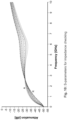
- FIG. 3 is a graph of simulated TDR time signals in a preparatory step of a simulation method for increasing the quality of a signal integrity of an HF plug-in connector;
- FIG. 4 is a graph of S-parameters corresponding to the TDR time signals of FIG. 3 in the preparatory step of the simulation method;
- FIG. 5 is a graph of a TDR time signal selected in the preparatory step as a representative for an HF plug-in connector for increasing the quality with which the simulation method is further continued;
- FIG. 6 is a graph of an S-parameter corresponding to the TDR time signal of FIG. 5 , also as a representative for the HF plug-in connector for quality improvement, with which the simulation method is continued;
- FIG. 7 is a graph of simulated TDR time signals in a design step of the simulation method for increasing the quality of a signal integrity of an HF plug-in connector
- FIG. 8 is a graph of line diagrams of S-parameters corresponding to the TDR time signals of FIG. 7 in the design step of the simulation method;
- FIG. 9 is a graph of line diagrams of simulated TDR time signals for impedance checking in the design step of the simulation method for improving quality
- FIG. 10 is a graph of line diagrams of S-parameters corresponding to the TDR time signals of FIG. 9 for impedance checking in the simulation method;
- FIG. 11 is a detail sectional perspective view of an HF plug-in connector with an HF compensation region according to an embodiment.
- FIG. 12 a detail sectional perspective view of an HF plug-in connector with an HF compensation region according to another embodiment.
- a feature of this specification cannot only be applied in a given manner, but also in a different manner (assembly, replacement, addition, unique position, omission etc.). It is in particular possible, on the basis of a reference sign and a feature assigned to it or vice versa, to replace, add or omit a feature.
- the features of the description can (from the point of view of the (initially generally unknown) prior art) also be interpreted as optional features. It is thus possible for a feature, in some cases including its periphery, to be detached from an exemplary embodiment, wherein this feature can then be transferred to a generalized inventive idea.
- the absence of a feature (negative feature) in an exemplary embodiment indicates that the feature is optional with respect to the invention.
- a species term for a feature can further also be read as a generic term for the feature (which may involve further hierarchical division into sub-classes etc.) whereby, for example, by considering equivalent effect and/or equivalent value, a generalization of the feature is possible.
- the invention is explained in more detail below with reference to exemplary embodiments of a variant of a high frequency (HF) plug-in connector 2 , 6 ; 40 of an HF plug-in connector 2 and an HF mating plug-in connector 6 , as shown in FIGS. 1 , 2 , 11 and 12 , for the vehicle sector in an embodiment.
- the invention is further explained in more detail with reference to exemplary embodiments of a variant of a method for increasing quality of a signal integrity of a male HF connector 2 and/or of an HF plug-in connector 2 , 6 ; 40 , as shown in FIGS. 3 to 10 , such as for the vehicle sector.
- Such an HF connector 2 is particularly suitable for an HF coaxial plug-in connector 2 , 6 ; 40 or an HF twisted pair plug-in connector 2 , 6 ; 40 .
- the HF connector 2 is designed as an HF connector 2 that can only be plugged in and not screwed.
- the invention is thus also generally applicable to a corresponding electrical constituent part and/or in a non-vehicle sector such as for example an entertainment electronics sector, a power electronics sector, an electrical engineering sector etc. and quite generally in technology.
- a non-vehicle sector such as for example an entertainment electronics sector, a power electronics sector, an electrical engineering sector etc. and quite generally in technology.
- This means that the invention is generally applicable to an electrical entity 1 , 5 .
- Ground-based electrical energy technology and its derivatives in vehicles form an exception here.
- Tolerances for the insertion depths of HF connectors 2 , 6 typically cause peaks in an impedance profile of an HF plug-in connector 2 , 6 ; 40 , for example from two high-speed data connectors for transmission rates above 1 GHz in the vehicle sector, as shown in FIG. 3 .
- the electrical signal travels along an electromagnetic path from an HF connector 2 / 6 , via the HF plug-in connector 2 , 6 ; 40 to the other HF connector 6 / 2 , or vice versa.
- Ideal preconditions for such an HF plug-in connector 2 , 6 ; 40 would be constant internal diameters and the same dielectric material within the HF plug-in connector 2 , 6 ; 40 with an impedance of, for example 50 ohms (see above). This means that there are no reflections, and that a very good signal integrity performance is ensured.
- the tolerances at the contact sections 110 , 510 can here add up to more than 1.4 mm. Other tolerance situations can of course also be handled according to the invention.
- these tolerances entail annular air gaps between the dielectric materials 20 , 60 of the HF terminals 10 , 50 .
- This means that a relevant HF terminal plug-in connector 2 , 6 ; 40 is here partially surrounded by an annular air gap. Since this annular air gap and the dielectric materials 20 , 60 that are adjacent in the two longitudinal directions have a significantly different permittivity, this has significant effects on the signal integrity of the HF plug-in connector 2 , 6 ; 40 .
- a dielectric air gap 4 arises between the dielectric materials 20 , 60 of the HF connector 2 , 6 in the HF plug-in connector 2 , 6 ; 40 , as shown in FIG. 1 .
- an inductive peak forms because of an erroneous impedance match in this region of the HF plug-in connector 2 , 6 ; 40 .
- This air gap 4 is unavoidable, and has significant negative effects on an HF performance of the HF plug-in connector 2 , 6 ; 40 .
- a typical axial tolerance range is about 1.4 mm, with the addition of about 1 mm additional overlap of the terminals 10 , 50 involved, so that the terminals 10 , 50 can also be securely plugged into one another (length of a contact region 110 , 510 of the terminal 10 , 50 greater than or equal to 2.4 mm).
- Each one of these HF connectors 2 , 6 comprises at least: radially outside, a screen conductor sleeve 30 , 70 , a dielectric material 20 , 60 provided radially inside the screen conductor sleeve 30 , 70 , and an HF terminal 10 , 50 provided radially inside in the dielectric material 20 , 60 , as shown in FIG. 1 .
- the screen conductor sleeve 30 , 70 does not here have to constitute a radially outward boundary of the HF connector 2 , 6 (housing, outer housing etc.).
- the HF connector 2 is designed as a male HF plug-in connector 2 with an (internal) male HF terminal 10
- the HF connector 6 as a female HF mating plug-in connector 6 with an (internal) female HF mating terminal 50 .
- the male HF terminal 10 is divided in its longitudinal direction Lr into an electromechanical contact section 110 with an insertion region 112 that is rounded or bevelled radially outside in an embodiment and is free at the front, a mechanical fastening section 120 in the dielectric material 20 , and an electromechanical connection section 130 that can, for example, be designed as a press-fit section, a soldered section, a welded section, a crimped section and so forth.
- the screen conductor sleeve 30 of the male HF connector 2 is constructed integrally with a header, which is, however, optional according to the invention.
- the HF terminal 10 can be constructed as a contact device (see above) or a contact apparatus (see above), and in particular as a pin terminal.
- the HF terminal 10 can if appropriate of course also be constructed as a tab terminal, a hermaphroditic terminal and so forth.
- the contact sections 110 , 510 provide an electromechanical contact of the HF terminal 10 with the HF mating terminal 50
- the fastening section 120 acts to provide a fastening of the HF terminal 10 in a dielectric 20 or in a housing
- the junction section acts to provide a further electromechanical contact of the HF terminal.
- the fastening section 120 can here comprise the junction section and/or can help to perform its tasks.
- the fastening section 120 and the junction section can consequently be housed in a common section in the HF terminal 10 .
- the female HF terminal 50 is divided in its longitudinal direction Lr into an electromechanical contact section 510 with an insertion region 512 that is rounded or bevelled radially inside in an embodiment and is free at the front, a mechanical fastening section 520 in the dielectric material 60 , and an electromechanical connection section 530 that in the present case can be designed as a crimped section, but also, for example, as a press-fit section, a soldered section, a welded section and so forth.
- the screen conductor sleeve 70 of the female HF connector 6 is constructed as a crimpable screen conductor sleeve 70 , which is, however, optional according to the invention.
- a final plugged-in position of the two HF terminals 10 , 50 i.e. of the HF terminal according to the invention with respect to the relevant mating terminal in the HF plug-in connector
- the in particular exclusively plugged-in (i.e. not (additionally) screwed) HF plug-in connector 2 , 6 ; 40 consisting of HF connector 2 and HF mating connector 6 is (also) subject to tolerance in the longitudinal direction Lr of the HF plug-in connector 2 , 6 ; 40 ; as is also the case with other plug-in connectors.
- This final plugged-in position, subject to tolerance has (see below) an effect on the signal integrity of the HF plug-in connector 2 , 6 ; 40 , or a certain loss of the signal integrity of the HF signal connector as a consequence.
- a compensation region 122 shown in FIG. 2 , is provided at/in the male HF terminal 10 in such a way that a loss in a signal integrity of the HF plug-in connector 2 , 6 ; 40 can be partially compensated and/or is partially compensated as a result of this HF compensation region 122 .
- the HF compensation region 122 refers to a form or shape at and/or in the HF terminal 10 which on the one hand differs from a conventional form of the HF terminal 10 in the longitudinal direction Lr in front of and/or behind the HF compensation region 122 , and on the other hand has the (passive) ability to compensate partially for the loss of the signal integrity of the HF plug-in connection.
- a certain loss of signal integrity of the HF plug-in connector 2 , 6 ; 40 can hereby be compensated for. This means that according to the invention a potential deterioration in the signal integrity of the HF plug-in connector 2 , 6 ; 40 resulting from the air gap 4 between the dielectric materials 20 , 60 of is countered by the HF compensation region 122 (static compensation).
- the HF compensation region 122 here acts as an impedance compensator, an impedance compensation device or an impedance compensation material.
- the design of the HF terminal 10 according to the invention helps to match the impedance caused in this region by the dielectric air gap 4 , and improves the HF performance of an HF plug-in connector 2 , 6 ; 40 .
- the HF compensation region 122 is here developed geometrically of one piece of material and fastened at/in the male HF terminal 10 or integrally constructed with the male HF terminal 10 .
- the compensation region 122 is in particular provided as a protuberance 122 of the HF terminal 10 .
- the compensation region 122 is provided aside from the contact section 110 at/in the male HF terminal 10 .
- the HF compensation region 122 can here be provided at/in the fastening section 120 or between the contact section 110 and the fastening section 120 at/in the HF terminal 10 .
- the HF compensation region 122 can here be arranged in an HF connector within a dielectric 20 , 60 , wherein the compensation region 122 acts as what may be the only (positive locking and/or friction locking) fastening of the HF terminal 10 , 50 in the dielectric 20 , 60 .
- the HF compensation region 122 can be provided or arranged at one side, two sides or multiple sides, around part of the circumference or around all of the circumference at/in the male HF terminal 10 .
- the HF compensation region 122 can here be divided into at least two molding regions that together form the HF compensation region 122 . This is, for example, the case with a two-sided HF compensation region 122 of the HF terminal 10 . It is of course possible to provide the HF compensation region 122 in a three-sided, four-sided, or many-sided form.
- the male HF terminal 10 has a rectangular or square cross-section, wherein the compensation region 122 is provided on two sides (above and below in FIG. 2 , transverse to the longitudinal direction Lr, flush with the two longitudinal sides of the male HF terminal 10 ).
- the male HF terminal 10 has an elliptical, circular, or quadratic cross-section, wherein the compensation region 122 is provided around the full circumference. It is of course possible for the compensation region 122 to be provided around part of the circumference.
- the HF terminal 10 can be designed as a straight, solid cylinder (male HF terminal).
- a base area of this solid cylinder can here be rectangular, in particular essentially square, elliptical, in particular essentially circular, prismatic and so forth.
- Cross-section of the HF compensation region 122 can be provided or arranged in the HF terminal point-symmetrically with respect to a longitudinal axis of the HF terminal 10 , or mirror-symmetrically with respect to a section plane of the HF terminal 10 .
- a size, a shape and/or a position of cross-section of the HF terminal 10 can be essentially identical in the longitudinal direction Lr in sections at least immediately in front of and/or behind the HF compensation region 122 .
- a cross-section of the HF terminal 10 , or a cross-section of the contact section 110 , of the fastening section and/or of the junction section—leaving aside the HF compensation region 122 can be rectangular, in particular essentially square, or elliptical, in particular essentially circular in design.
- the HF compensation region 122 can be arranged as a protuberance in a central section of the HF terminal 10 .
- the protuberance can here, depending on a design of the HF terminal 10 and its cross-section, be provided or arranged altogether as a rectangular solid, cuboid, possibly on one side or partially surrounding on more than one side; or have the shape of an ellipsoid, an oval, or sphere.
- At least some of the cross-section or all of the cross-section of a longitudinal section of the HF compensation region 122 , of the protuberance or of a molding region can here be the same as and flush with one another in the longitudinal direction Lr.
- the HF terminal 10 can be designed as an HF terminal 10 that can only be plugged in and not screwed.
- the HF terminal 10 can here be manufactured for example through a punching process and a shaping process (pressing process, stamping process etc.) that may follow it in time, by a turning process, as a compressed wire and so forth.
- the HF terminal 10 with its HF compensation region 122 or its protuberance can be designed as a single or integral piece of material.
- An integral design refers to formation of the HF terminal 10 in which there is only a single component which can only be divided destructively. The component is manufactured from a single starting piece (metal sheet, blank etc.) and/or from a single starting mass (molten metal), which is therefore necessarily integral for its part. It is held together internally by adhesion and/or cohesion.
- a materially (adhesively) one-piece design refers to a design of the HF terminal whose individual parts are fixed to one another materially (welding, soldering, gluing etc.), and which cannot be separated into its individual parts without damage to one of its individual parts. The cohesion can here furthermore be created by means of a friction and/or positive locking (not with integral design).
- a suitable dimension, or diameter, of the compensation region 122 or of the male HF terminal 10 in the compensation region 122 is determined by the method according to the invention for increasing quality.
- a position of the compensation region 122 in the longitudinal direction Lr at/in the male HF terminal 10 is here essentially negligible, as is a position in the circumferential direction at/in the male HF terminal 10 .
- a radial dimension of the compensation region 122 for example is, however, important e.g. in a single radial direction (one-sided compensation region 122 ) in two mutually opposed radial directions (two-sided, in an embodiment symmetrical compensation region 122 ) and in all radial directions (compensation region 122 around the full circumference).
- the method is carried out as a computer-aided simulation method. It is, of course, also possible not to simulate the relevant data but to measure at real HF plug-in connectors 2 , 6 ; 40 .
- this assembly is first converted to a computer model.
- the air gap 4 between the dielectric materials 20 , 60 in particular can, furthermore, be configured in the preparatory step.
- the air gap 4 remains configured during the entire process, and has a specific diameter, e.g.: 0.35 mm, 0.4 mm, 0.45 mm, 0.5 mm, 0.55 mm, 0.6 mm, 0.7 mm, 0.8 mm, or 1.0 mm.
- a preparatory step I of the method at least one uncompensated signal integrity of the HF plug-in connector 2 , 6 ; 40 is determined with reference to this computer model.
- the male HF terminal 10 and the HF plug-in connector 2 , 6 ; 40 should here have a previously selected, specific impedance of, for example, 50 ohms. If this is not the case, the relevant diameters of the male HF terminal 10 and of the HF plug-in connector 2 , 6 ; 40 must be determined, and the HF terminal 10 and the HF plug-in connector 2 , 6 ; 40 appropriately configured.
- a typical diameter of e.g. 0.4 mm or 0.5 mm of the male HF terminal 10 is here freely selected, and following this a geometry of the screen conductor sleeve 30 , in particular its internal diameter, or of the header, determined for this impedance.
- This takes place using the time-domain reflectometer (TDR) time signals I to VI shown in FIG. 3 .
- the desired impedance of 50 ohms is located between the signals III and IV, which represent specific geometries.
- Other impedances such as, for example, 75 ohms, 93-125 ohms etc. can of course be used.
- the geometry for the relevant impedance can be determined hereby.
- FIG. 4 shows the S-parameters corresponding to the TDR time signals I to VI.
- FIG. 5 shows the TDR time signal (TDR time signal between the signals III and IV of FIG. 3 ) selected in the preparatory step I for the desired 50 ohms.
- FIG. 6 shows the S-parameters corresponding to this which represent the reference S-parameters on the basis of which the compensation region 122 according to the invention has to be measured; i.e. it must demonstrate reduced attenuation here for an improvement of the quality.
- a geometrically determined HF compensation region 122 is now provided at/in the male HF terminal 10 , aside from its contact region 110 , and a compensated signal integrity of the HF plug-in connector is determined in the computer model. This is repeated with geometrically different HF compensation regions 122 .
- the design step II is, in an embodiment, directly subsequent to the preparatory step I.
- FIG. 8 shows the S-parameters corresponding to the TDR time signals of FIG. 7 . It is found, as shown in FIG. 8 , that larger dimensions or diameters of the HF compensation regions 122 are worse at lower frequencies than at higher frequencies. Starting from the requirements, in particular for a transmission frequency, placed on an HF plug-in connector 2 , 6 ; 40 that is to be designed, a suitable dimension or a suitable diameter for the compensation region 122 is to be selected. The simulation method further shows that with the design of the HF plug-in connector 2 , 6 ; 40 used, and in particular of the male HF terminal 10 that can be developed thereby, an HF performance at specific frequencies or frequency bands (here greater than about 2.4 to 2.7 GHz up to more than 10 GHz, FIG. 8 ) can be improved.
- frequencies or frequency bands here greater than about 2.4 to 2.7 GHz up to more than 10 GHz, FIG. 8
- a specific dimension, in some cases a specific form (e.g. determined by the dimension) and/or in some cases a specific position (e.g. determined by the dimension), of the compensation region 122 is selected and correspondingly configured at/in the HF terminal 10 .
- an impedance check related to the desired impedance can take place in the design step II.
- a geometry or dimension of the male HF connector 2 in particular of a diameter of its screen conductor sleeve 30 , of the HF plug-in connector 2 , 6 ; 40 and/or of the HF compensation region 122 can be adjusted.
- the air gap 4 is designed according to the invention as a fully surrounding annular air gap.
- the compensation region 122 can be further improved.
- the compensation region 122 can thus have a constant diameter only partially in the longitudinal direction Lr and can further comprise a bevel ( FIG. 11 ) or may be completely constituted of a bevel ( FIG. 12 ).
- the compensation region 122 can here again be formed on one side, two sides, multiple sides, partially around the circumference, fully around the circumference and so forth.
- the HF plug-in connector 2 , 6 ; 40 according to the invention comprises a male HF connector 2 and a female HF connector 6 , wherein at least one of the HF connectors 2 , 6 is designed according to the invention, and/or the HF connector 2 , 6 or the HF plug-in connector 2 , 6 ; 40 was or were or is or are designed by a method according to the invention.
- the electrical entity according to the invention comprises an HF connector 2 or an HF plug-in connector 2 , 6 ; 40 , wherein the HF connector 2 and/or the HF-plug-in connector 2 , 6 ; 40 is designed according to the invention, and/or the HF connector 2 or the HF plug-in connector 2 , 6 ; 40 has been or is configured by a method according to the invention.
- Such an entity is, for example, configured as an electrical device, an electrical apparatus, a (pre-)assembled electrical HF cable, an electrical assembly, an electrical circuit board, an electrical constituent part, an electrical module, an electrical device, an electrical apparatus, an electrical aggregate, an electrical installation, an electrical system and so forth.
- the invention counteracts a deterioration of a signal integrity, also referred to as the terminal spacing effect, in HF plug-in connectors, for example in HF coaxial plug-in connectors or HF twisted pair plug-in connectors, in order to improve a transmittable bandwidth (improvement of the signal integrity) of a relevant HF plug-in connector.
- the invention reduces a negative effect on a realizable bandwidth at higher frequencies of the relevant HF plug-in connector resulting from an air gap in a region of the plugged in HF terminals (see also FIG. 8 ).
Landscapes
- Details Of Connecting Devices For Male And Female Coupling (AREA)
Abstract
Description
Claims (20)
Applications Claiming Priority (2)
| Application Number | Priority Date | Filing Date | Title |
|---|---|---|---|
| DE102019130743.0 | 2019-11-14 | ||
| DE102019130743.0A DE102019130743A1 (en) | 2019-11-14 | 2019-11-14 | HF terminal for an HF connector, as well as a method for increasing the quality of the signal integrity of a male HF connector or an HF plug connection |
Publications (2)
| Publication Number | Publication Date |
|---|---|
| US20210151937A1 US20210151937A1 (en) | 2021-05-20 |
| US11984686B2 true US11984686B2 (en) | 2024-05-14 |
Family
ID=73401410
Family Applications (1)
| Application Number | Title | Priority Date | Filing Date |
|---|---|---|---|
| US17/096,067 Active 2041-01-15 US11984686B2 (en) | 2019-11-14 | 2020-11-12 | HF terminal for an HF connector, and a method for improving the quality of a signal integrity of a male HF connector or of an HF plug-in connector |
Country Status (6)
| Country | Link |
|---|---|
| US (1) | US11984686B2 (en) |
| EP (1) | EP3823109A1 (en) |
| JP (1) | JP7744097B2 (en) |
| KR (1) | KR102851889B1 (en) |
| CN (1) | CN112803184B (en) |
| DE (1) | DE102019130743A1 (en) |
Families Citing this family (3)
| Publication number | Priority date | Publication date | Assignee | Title |
|---|---|---|---|---|
| EP3869631B1 (en) * | 2020-02-18 | 2025-07-30 | ERICH JAEGER GmbH + Co. KG | Data plug-in connection adapter for data transmission and motor vehicle plug with data plug-in connection adapter |
| DE102022202848A1 (en) * | 2022-03-23 | 2023-09-28 | Yamaichi Electronics Deutschland Gmbh | Contact element, contact element system and connector |
| DE102022202850A1 (en) * | 2022-03-23 | 2023-09-28 | Yamaichi Electronics Deutschland Gmbh | Contact element, contact element system and connector |
Citations (12)
| Publication number | Priority date | Publication date | Assignee | Title |
|---|---|---|---|---|
| US2688737A (en) * | 1950-01-13 | 1954-09-07 | American Phenolic Corp | Hermetically sealed connector |
| DE1795755U (en) | 1959-02-03 | 1959-09-17 | Siemens Ag | REFLECTION-FREE CONNECTION FOR TWO COAXIAL LINES OF DIFFERENT REAL WIDTH. |
| US3290639A (en) * | 1962-09-14 | 1966-12-06 | Joy Mfg Co | Connector |
| US4737124A (en) * | 1985-05-13 | 1988-04-12 | Hosiden Electronics Co., Ltd. | Connector plug |
| US4909751A (en) * | 1988-09-20 | 1990-03-20 | The United States Of America As Represented By The Secretary Of The Navy | Underwater mateable electrical connector |
| EP0380892A1 (en) | 1989-01-20 | 1990-08-08 | Alliance Technique Industrielle | Ultra-miniature high-frequency connection interface |
| US5217391A (en) * | 1992-06-29 | 1993-06-08 | Amp Incorporated | Matable coaxial connector assembly having impedance compensation |
| US5474470A (en) | 1994-03-30 | 1995-12-12 | Itt Corporation | Compensated interface coaxial connector apparatus |
| US7071416B2 (en) * | 2003-03-27 | 2006-07-04 | C.R.F. Societa Consortile Per Azioni | Connector member for electrical connections through a wall of a fuel tank, particularly for the LPG fuel tank of a motor vehicle |
| US8113860B2 (en) * | 2009-09-04 | 2012-02-14 | Graeme Richard Sandwith | High power multi-pin electrical connector |
| US20150325956A1 (en) * | 2012-06-18 | 2015-11-12 | HARTING Electronics GmbH | Insulation body of a plug-in connector |
| US20180048101A1 (en) | 2016-08-09 | 2018-02-15 | Hirose Electric Co., Ltd. | Coaxial connector |
Family Cites Families (8)
| Publication number | Priority date | Publication date | Assignee | Title |
|---|---|---|---|---|
| JPS6433177U (en) * | 1987-08-21 | 1989-03-01 | ||
| DE50100570D1 (en) * | 2000-04-22 | 2003-10-09 | Spinner Gmbh Elektrotech | Connector for coaxial cable with thin-walled cable outer conductor |
| US7808341B2 (en) * | 2007-02-21 | 2010-10-05 | Kyocera America, Inc. | Broadband RF connector interconnect for multilayer electronic packages |
| CN100553052C (en) * | 2007-12-26 | 2009-10-21 | 罗森伯格亚太电子有限公司 | Interface of coaxial cable connector |
| DE102010028672B4 (en) * | 2010-05-06 | 2015-07-02 | Tyco Electronics Amp Gmbh | Plug connection with lash adjuster |
| JP2012094421A (en) * | 2010-10-28 | 2012-05-17 | Sumitomo Wiring Syst Ltd | Protector |
| US10165670B2 (en) * | 2016-04-29 | 2018-12-25 | Deere & Company | Electrical connector assembly |
| JP6551764B1 (en) * | 2018-08-07 | 2019-07-31 | Smk株式会社 | Coaxial connector |
-
2019
- 2019-11-14 DE DE102019130743.0A patent/DE102019130743A1/en active Pending
-
2020
- 2020-11-11 JP JP2020187652A patent/JP7744097B2/en active Active
- 2020-11-12 US US17/096,067 patent/US11984686B2/en active Active
- 2020-11-12 CN CN202011261019.3A patent/CN112803184B/en active Active
- 2020-11-12 KR KR1020200151190A patent/KR102851889B1/en active Active
- 2020-11-12 EP EP20207222.9A patent/EP3823109A1/en active Pending
Patent Citations (15)
| Publication number | Priority date | Publication date | Assignee | Title |
|---|---|---|---|---|
| US2688737A (en) * | 1950-01-13 | 1954-09-07 | American Phenolic Corp | Hermetically sealed connector |
| DE1795755U (en) | 1959-02-03 | 1959-09-17 | Siemens Ag | REFLECTION-FREE CONNECTION FOR TWO COAXIAL LINES OF DIFFERENT REAL WIDTH. |
| US3290639A (en) * | 1962-09-14 | 1966-12-06 | Joy Mfg Co | Connector |
| US4737124A (en) * | 1985-05-13 | 1988-04-12 | Hosiden Electronics Co., Ltd. | Connector plug |
| US4909751A (en) * | 1988-09-20 | 1990-03-20 | The United States Of America As Represented By The Secretary Of The Navy | Underwater mateable electrical connector |
| EP0380892A1 (en) | 1989-01-20 | 1990-08-08 | Alliance Technique Industrielle | Ultra-miniature high-frequency connection interface |
| US5074809A (en) | 1989-01-20 | 1991-12-24 | Alliance Technique Industrielle | Ultraminiature high-frequency connection interface |
| US5217391A (en) * | 1992-06-29 | 1993-06-08 | Amp Incorporated | Matable coaxial connector assembly having impedance compensation |
| US5474470A (en) | 1994-03-30 | 1995-12-12 | Itt Corporation | Compensated interface coaxial connector apparatus |
| US7071416B2 (en) * | 2003-03-27 | 2006-07-04 | C.R.F. Societa Consortile Per Azioni | Connector member for electrical connections through a wall of a fuel tank, particularly for the LPG fuel tank of a motor vehicle |
| US8113860B2 (en) * | 2009-09-04 | 2012-02-14 | Graeme Richard Sandwith | High power multi-pin electrical connector |
| US20150325956A1 (en) * | 2012-06-18 | 2015-11-12 | HARTING Electronics GmbH | Insulation body of a plug-in connector |
| US9362679B2 (en) * | 2012-06-18 | 2016-06-07 | HARTING Electronics GmbH | Insulation body of a plug-in connector |
| US20180048101A1 (en) | 2016-08-09 | 2018-02-15 | Hirose Electric Co., Ltd. | Coaxial connector |
| US10164384B2 (en) * | 2016-08-09 | 2018-12-25 | Hirose Electric Co., Ltd. | Coaxial connector |
Non-Patent Citations (2)
| Title |
|---|
| European Patent Office Communication, dated May 4, 2023, corresponding to Application No. 20 207 222.9-1201, 11 pages. |
| European Patent Office, dated Mar. 15, 2021, 16 pages. |
Also Published As
| Publication number | Publication date |
|---|---|
| CN112803184B (en) | 2026-03-13 |
| CN112803184A (en) | 2021-05-14 |
| KR20210058716A (en) | 2021-05-24 |
| JP2021082582A (en) | 2021-05-27 |
| KR102851889B1 (en) | 2025-08-28 |
| DE102019130743A1 (en) | 2021-05-20 |
| JP7744097B2 (en) | 2025-09-25 |
| US20210151937A1 (en) | 2021-05-20 |
| EP3823109A1 (en) | 2021-05-19 |
Similar Documents
| Publication | Publication Date | Title |
|---|---|---|
| US10468786B2 (en) | Electrical connection device, a method of manufacturing an electrical cable and a manufactured electrical coaxial cable | |
| US11984686B2 (en) | HF terminal for an HF connector, and a method for improving the quality of a signal integrity of a male HF connector or of an HF plug-in connector | |
| JP7146544B2 (en) | Methods of assembling electrical contact devices, electrical connection units and electrical cables | |
| EP3487007A2 (en) | High frequency electrical connector | |
| KR102666891B1 (en) | Method for crimping an electrical hf-connecting device | |
| US9620905B2 (en) | Vehicular cable assembly | |
| JP2012129103A (en) | Coaxial connector | |
| CN101884144A (en) | Coaxial plug connector with coded housing | |
| JP6121537B2 (en) | Plug connection | |
| US20210257784A1 (en) | Data connector adapter for data transmission and motor vehicle socket with data connector adapter | |
| JP2015500552A (en) | Method for manufacturing insertion type connector | |
| US9281640B2 (en) | Connector | |
| US10727623B2 (en) | Electrical connecting unit and sealing arrangement for an electrical connector and method for its production | |
| CN114759405A (en) | High-reliability filtering electric connector socket or plug | |
| CN217848536U (en) | High-reliability filtering electric connector for socket or plug | |
| CN116315890A (en) | Electrical plug connectors, electrical mating plug connectors and electrical plug connection devices | |
| KR102893629B1 (en) | Contact module with improved shielding and monolithically folded housing | |
| CN220066336U (en) | Coaxial connector structure | |
| US20260045745A1 (en) | Electrical connector for automotive applications | |
| CN102055091B (en) | Plug connector, socket connector and electric connector combination thereof | |
| CN107732605B (en) | Coaxial contact module | |
| JP7754467B2 (en) | High frequency impedance matched edge launch RF connector | |
| WO2019082451A1 (en) | Shield connector connection method and shield connector | |
| JPWO2018221110A1 (en) | L-shaped coaxial connector and L-shaped coaxial connector with coaxial cable | |
| JP2019096502A (en) | Signal transmission system |
Legal Events
| Date | Code | Title | Description |
|---|---|---|---|
| FEPP | Fee payment procedure |
Free format text: ENTITY STATUS SET TO UNDISCOUNTED (ORIGINAL EVENT CODE: BIG.); ENTITY STATUS OF PATENT OWNER: LARGE ENTITY |
|
| AS | Assignment |
Owner name: TE CONNECTIVITY GERMANY GMBH, GERMANY Free format text: ASSIGNMENT OF ASSIGNORS INTEREST;ASSIGNORS:YOGENDRA, DEEKSHA VENKADARI;VOLKMANN, DANIEL;KARRASCH, GREGOR;REEL/FRAME:054414/0727 Effective date: 20201118 |
|
| STPP | Information on status: patent application and granting procedure in general |
Free format text: APPLICATION DISPATCHED FROM PREEXAM, NOT YET DOCKETED |
|
| STPP | Information on status: patent application and granting procedure in general |
Free format text: DOCKETED NEW CASE - READY FOR EXAMINATION |
|
| STPP | Information on status: patent application and granting procedure in general |
Free format text: NON FINAL ACTION MAILED |
|
| STPP | Information on status: patent application and granting procedure in general |
Free format text: RESPONSE TO NON-FINAL OFFICE ACTION ENTERED AND FORWARDED TO EXAMINER |
|
| STPP | Information on status: patent application and granting procedure in general |
Free format text: FINAL REJECTION MAILED |
|
| STPP | Information on status: patent application and granting procedure in general |
Free format text: ADVISORY ACTION MAILED |
|
| STPP | Information on status: patent application and granting procedure in general |
Free format text: DOCKETED NEW CASE - READY FOR EXAMINATION |
|
| STPP | Information on status: patent application and granting procedure in general |
Free format text: NON FINAL ACTION MAILED |
|
| STPP | Information on status: patent application and granting procedure in general |
Free format text: NON FINAL ACTION MAILED |
|
| STPP | Information on status: patent application and granting procedure in general |
Free format text: RESPONSE TO NON-FINAL OFFICE ACTION ENTERED AND FORWARDED TO EXAMINER |
|
| STPP | Information on status: patent application and granting procedure in general |
Free format text: FINAL REJECTION MAILED |
|
| STPP | Information on status: patent application and granting procedure in general |
Free format text: RESPONSE AFTER FINAL ACTION FORWARDED TO EXAMINER |
|
| STPP | Information on status: patent application and granting procedure in general |
Free format text: NOTICE OF ALLOWANCE MAILED -- APPLICATION RECEIVED IN OFFICE OF PUBLICATIONS |
|
| ZAAB | Notice of allowance mailed |
Free format text: ORIGINAL CODE: MN/=. |
|
| STPP | Information on status: patent application and granting procedure in general |
Free format text: PUBLICATIONS -- ISSUE FEE PAYMENT RECEIVED |
|
| STPP | Information on status: patent application and granting procedure in general |
Free format text: PUBLICATIONS -- ISSUE FEE PAYMENT VERIFIED |
|
| STCF | Information on status: patent grant |
Free format text: PATENTED CASE |