US11956014B2 - Method and system for transmitting and receiving an electromagnetic radiation beam with detection of orbital angular momentum and related telecommunication method and system - Google Patents
Method and system for transmitting and receiving an electromagnetic radiation beam with detection of orbital angular momentum and related telecommunication method and system Download PDFInfo
- Publication number
- US11956014B2 US11956014B2 US17/603,085 US202017603085A US11956014B2 US 11956014 B2 US11956014 B2 US 11956014B2 US 202017603085 A US202017603085 A US 202017603085A US 11956014 B2 US11956014 B2 US 11956014B2
- Authority
- US
- United States
- Prior art keywords
- electrical signal
- electromagnetic radiation
- phase
- main
- modulated
- Prior art date
- Legal status (The legal status is an assumption and is not a legal conclusion. Google has not performed a legal analysis and makes no representation as to the accuracy of the status listed.)
- Active
Links
- 230000005670 electromagnetic radiation Effects 0.000 title claims abstract description 147
- 238000000034 method Methods 0.000 title claims abstract description 94
- 238000001514 detection method Methods 0.000 title claims description 18
- 239000002131 composite material Substances 0.000 claims description 110
- 238000001228 spectrum Methods 0.000 claims description 16
- 239000013598 vector Substances 0.000 claims description 12
- 230000001419 dependent effect Effects 0.000 claims description 11
- 230000003287 optical effect Effects 0.000 claims description 10
- 230000005540 biological transmission Effects 0.000 claims description 6
- 238000000926 separation method Methods 0.000 claims description 4
- 238000001914 filtration Methods 0.000 claims description 2
- 230000001902 propagating effect Effects 0.000 description 6
- 238000010586 diagram Methods 0.000 description 5
- 230000005684 electric field Effects 0.000 description 4
- 238000004458 analytical method Methods 0.000 description 3
- 238000012512 characterization method Methods 0.000 description 3
- 230000014509 gene expression Effects 0.000 description 2
- 230000005672 electromagnetic field Effects 0.000 description 1
- 230000005855 radiation Effects 0.000 description 1
Images


Classifications
-
- H—ELECTRICITY
- H04—ELECTRIC COMMUNICATION TECHNIQUE
- H04B—TRANSMISSION
- H04B10/00—Transmission systems employing electromagnetic waves other than radio-waves, e.g. infrared, visible or ultraviolet light, or employing corpuscular radiation, e.g. quantum communication
- H04B10/11—Arrangements specific to free-space transmission, i.e. transmission through air or vacuum
- H04B10/118—Arrangements specific to free-space transmission, i.e. transmission through air or vacuum specially adapted for satellite communication
-
- G—PHYSICS
- G02—OPTICS
- G02F—OPTICAL DEVICES OR ARRANGEMENTS FOR THE CONTROL OF LIGHT BY MODIFICATION OF THE OPTICAL PROPERTIES OF THE MEDIA OF THE ELEMENTS INVOLVED THEREIN; NON-LINEAR OPTICS; FREQUENCY-CHANGING OF LIGHT; OPTICAL LOGIC ELEMENTS; OPTICAL ANALOGUE/DIGITAL CONVERTERS
- G02F2/00—Demodulating light; Transferring the modulation of modulated light; Frequency-changing of light
- G02F2/004—Transferring the modulation of modulated light, i.e. transferring the information from one optical carrier of a first wavelength to a second optical carrier of a second wavelength, e.g. all-optical wavelength converter
- G02F2/008—Opto-electronic wavelength conversion, i.e. involving photo-electric conversion of the first optical carrier
-
- H—ELECTRICITY
- H04—ELECTRIC COMMUNICATION TECHNIQUE
- H04B—TRANSMISSION
- H04B10/00—Transmission systems employing electromagnetic waves other than radio-waves, e.g. infrared, visible or ultraviolet light, or employing corpuscular radiation, e.g. quantum communication
- H04B10/11—Arrangements specific to free-space transmission, i.e. transmission through air or vacuum
-
- H—ELECTRICITY
- H04—ELECTRIC COMMUNICATION TECHNIQUE
- H04B—TRANSMISSION
- H04B10/00—Transmission systems employing electromagnetic waves other than radio-waves, e.g. infrared, visible or ultraviolet light, or employing corpuscular radiation, e.g. quantum communication
- H04B10/50—Transmitters
- H04B10/516—Details of coding or modulation
- H04B10/54—Intensity modulation
- H04B10/541—Digital intensity or amplitude modulation
-
- H—ELECTRICITY
- H04—ELECTRIC COMMUNICATION TECHNIQUE
- H04B—TRANSMISSION
- H04B7/00—Radio transmission systems, i.e. using radiation field
- H04B7/02—Diversity systems; Multi-antenna system, i.e. transmission or reception using multiple antennas
- H04B7/04—Diversity systems; Multi-antenna system, i.e. transmission or reception using multiple antennas using two or more spaced independent antennas
- H04B7/06—Diversity systems; Multi-antenna system, i.e. transmission or reception using multiple antennas using two or more spaced independent antennas at the transmitting station
- H04B7/0613—Diversity systems; Multi-antenna system, i.e. transmission or reception using multiple antennas using two or more spaced independent antennas at the transmitting station using simultaneous transmission
- H04B7/0615—Diversity systems; Multi-antenna system, i.e. transmission or reception using multiple antennas using two or more spaced independent antennas at the transmitting station using simultaneous transmission of weighted versions of same signal
- H04B7/0617—Diversity systems; Multi-antenna system, i.e. transmission or reception using multiple antennas using two or more spaced independent antennas at the transmitting station using simultaneous transmission of weighted versions of same signal for beam forming
-
- H—ELECTRICITY
- H04—ELECTRIC COMMUNICATION TECHNIQUE
- H04B—TRANSMISSION
- H04B7/00—Radio transmission systems, i.e. using radiation field
- H04B7/14—Relay systems
- H04B7/15—Active relay systems
- H04B7/185—Space-based or airborne stations; Stations for satellite systems
- H04B7/1851—Systems using a satellite or space-based relay
- H04B7/18515—Transmission equipment in satellites or space-based relays
-
- H—ELECTRICITY
- H04—ELECTRIC COMMUNICATION TECHNIQUE
- H04J—MULTIPLEX COMMUNICATION
- H04J14/00—Optical multiplex systems
- H04J14/02—Wavelength-division multiplex systems
-
- H—ELECTRICITY
- H04—ELECTRIC COMMUNICATION TECHNIQUE
- H04J—MULTIPLEX COMMUNICATION
- H04J14/00—Optical multiplex systems
- H04J14/07—Orbital angular momentum [OAM] multiplex systems
Definitions
- the present invention generally relates to the technical field of the transmission and reception of electromagnetic beams, in particular optical/laser and microwave beams, with detection of the orbital angular momentum of such beams, as well as to the field of telecommunications based on electromagnetic beams, in particular optical/laser and microwave beams, orbital angular momentum-modulated and/or -multiplexed.
- the orbital angular momentum is a concept related to the different transversal modes of beam propagation.
- OAM Orbital Angular Momentum
- the Poynting vector as well as the wave vector, is no longer simply parallel to the direction of propagation, but twists about it.
- the orbital angular momentum is treated, from a quantum point of view, through a further quantum number, which is distinct from the spin.
- the “orbital angular momentum” variable due to the features thereof mentioned above, is particularly difficult to be detected and characterized when the detector is illuminated only by a limited portion of the radiation beam, even if very distant from the singularity.
- the need is felt to detect the orbital angular momentum of a beam received for various reasons, including, for example, the characterization of the beam and the utilization of the angular momentum variable for telecommunications purposes.
- the Applicant has also identified a promising possibility of utilizing the orbital angular momentum variable as an additional degree of freedom, advantageously usable both for modulating signals and for multiplexing the same.
- Such an object is achieved by a method according to claim 1 .
- the present invention further relates to a system for transmitting and receiving an electromagnetic radiation beam, capable of performing the aforesaid method.
- a system for transmitting and receiving an electromagnetic radiation beam capable of performing the aforesaid method.
- the present invention also relates to a method for performing a telecommunication of signals modulated according to any modulation technique and grouped by means of orbital angular momentum multiplexing. Such a method is defined in claim 16 .
- the present invention further relates to a telecommunication system, capable of performing the aforesaid method for performing a telecommunication of modulated signals.
- a system is defined in claims 25 and 26 .
- FIG. 1 shows a simplified diagram of a transmitting portion of an embodiment of the system for transmitting and receiving an electromagnetic radiation beam, in accordance with the invention; such a FIG. 1 simultaneously shows some steps of the corresponding method;
- FIG. 2 shows a simplified diagram of a receiving portion of an embodiment of the system for transmitting and receiving an electromagnetic radiation beam, in accordance with the invention; such a FIG. 2 simultaneously shows some other steps of the corresponding method;
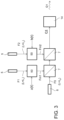
- FIG. 3 shows a simplified diagram of a transmitting portion of an embodiment of the telecommunication system in accordance with the invention; such a FIG. 3 simultaneously shows some steps of the corresponding method;
- FIG. 4 shows a simplified diagram of a receiving portion of an embodiment of the telecommunication system in accordance with the invention; such a FIG. 4 simultaneously shows some other steps of the corresponding method;
- FIG. 5 shows an embodiment of the systems in accordance with the invention, comprising correlators
- FIG. 6 depicts some geometric quantities used in the illustration of the system.
- a method for transmitting and receiving an electromagnetic radiation beam is described, adapted to determine an orbital angular momentum of the received electromagnetic radiation beam.
- the method comprises the steps of generating at least one main electromagnetic radiation beam F 1 characterized by a first orbital angular momentum L 1 , by a first spectrum in a first frequency band, and by a first beam radius of curvature, and of generating a reference electromagnetic radiation beam F 0 , characterized by a second orbital angular momentum L 0 , by a second spectrum in a second frequency band which is distinct from the aforesaid first frequency band, and by a second beam radius of curvature substantially coinciding with the aforesaid first beam radius of curvature.
- the method therefore involves generating a composite electromagnetic radiation beam Q 1 , consisting of the superposition of the aforesaid at least one main beam F 1 and reference beam F 0 , and transmitting the composite electromagnetic radiation beam Q 1 thus generated.
- the method further comprises the steps of receiving the aforesaid composite electromagnetic radiation beam Q 1 , by means of a first beam detector 1 located in a first position, to generate a first composite beam electrical signal D 1 , representative of the electric and/or magnetic field and/or of the intensity of the electromagnetic radiation of the composite beam in such a first position; and receiving the aforesaid composite electromagnetic radiation beam Q 1 , by means of a second beam detector 2 located in a second different position with respect to the aforesaid first position, to generate a second composite beam electrical signal D 2 , representative of the electric and/or magnetic field and/or of the intensity of the received electromagnetic radiation of the composite beam in such a second position.
- the method further comprises the steps of performing a frequency discrimination of the first composite beam electrical signal D 1 to obtain a first main beam electrical signal P 1 , representative of the electric and/or magnetic field and/or of the intensity due to the main beam in said first position, and a first reference beam electrical signal R 1 , representative of the electric and/or magnetic field and/or of the intensity due to the reference beam in the first position; and performing a frequency discrimination of the second composite beam electrical signal D 2 to obtain a second main beam electrical signal P 2 , representative of the electric and/or magnetic field and/or of the intensity due to the main beam in the second position, and a second reference beam electrical signal R 2 , representative of the electric and/or magnetic field and/or of the intensity due to the reference beam in the second position.
- the method finally involves determining the orbital angular momentum L 1 of the main electromagnetic radiation beam and/or the spatial phase variation of the main electromagnetic radiation beam due to the main beam orbital angular momentum L 1 , based on the aforesaid first main beam electrical signal P 1 , second main beam electrical signal P 2 , first reference beam electrical signal R 1 and second reference beam electrical signal R 2 .
- positional inclination (or “positional tilt”) is meant to indicate the angle formed between the straight line joining the two detectors and the (orthogonal) projection thereof on the plane orthogonal to the beam propagation axis.
- the step of determining the orbital angular momentum of the main electromagnetic radiation beam comprises determining the orbital angular momentum of the main electromagnetic radiation beam based on the formula: ⁇ P/k ⁇ R/k′ ⁇ ( L 1 /k ⁇ L 0 /k ′)( ⁇ 2 ⁇ 1 ) where ⁇ 1 is the angular position of the first detector measured on the plane orthogonal to the composite beam propagation vector containing the first detector; ⁇ 2 is the angular position of the second detector measured on the plane orthogonal to the composite beam propagation vector containing the second detector; ⁇ indicates proportionality.
- the step of determining a first phase difference value ⁇ P comprises comparing the phase of the first main beam electrical signal P 1 with the phase of the second main beam electrical signal P 2 , by means of a first phase comparator 3 ;
- the step of determining a second phase difference value ⁇ R comprises comparing the phase of the first reference beam electrical signal R 1 with that of the second reference beam electrical signal R 2 , by means of a second phase comparator 4 .
- the step of determining a first phase difference value ⁇ P comprises performing correlation operations between the first main beam electrical signal P 1 and the second main beam electrical signal P 2 ; and the step of determining a second phase difference value ⁇ R comprises performing correlation operations between the first reference beam electrical signal R 1 and the second reference beam electrical signal R 2 .
- the orbital angular momentum of the reference beam is known at all times.
- the first position of the first detector 1 and the second position of the second detector 2 are fixed and constant, and are distinct from the position of the singularity point of the beam.
- the first position of the first detector 1 and/or the second position of the second detector 2 are movable, and the reciprocal relationship between the aforesaid first position and second position is known at all times.
- the second frequency band is substantially monochromatic.
- the second frequency band is adjacent to the first frequency band.
- the steps of performing a frequency discrimination of the first or second composite beam electrical signal comprise performing a frequency filtering, or performing a frequency separation by means of heterodyne techniques or other frequency separation methods.
- the at least one main electromagnetic radiation beam is not modulated.
- the at least one main electromagnetic radiation beam is amplitude-modulated, and/or phase-modulated, and/or frequency-modulated, and/or orbital angular momentum-modulated.
- all the transmitted and received electromagnetic beams are optical beams and/or laser beams.
- first composite beam electrical signal D 1 , second composite beam electrical signal D 2 , first main beam electrical signal P 1 , first reference beam electrical signal R 1 , second main beam electrical signal P 2 , second reference beam electrical signal of are indicated, for simplicity, with the same name as the respective signal.
- the main beam may be modulated or unmodulated.
- the reference beam has a frequency band which is not overlapping the frequency band of the main beam.
- the frequency band of the reference beam is preferably quasi-monochromatic and adjacent to the frequency band of the main beam.
- the reference beam substantially has the same curvature and the same propagation vector as the main beam.
- the recognition of the spatial phase difference generated by the main beam with an orbital angular momentum L 1 is obtained by using two detectors in positions arbitrary in the space with the exception of the singularity point of the vortex.
- the expression “singularity of the vortex” means a point in the vortex in which the electromagnetic field results to be reduced to zero and in which the phase of the field cannot be determined.
- t is time
- a 1 and B 1 are non-zero arbitrary amplitudes
- l 1 is the topological charge of the main beam
- l 0 is the topological charge of the reference beam
- ⁇ 1 is the angular position of the detector measured on the plane orthogonal to the composite beam propagation vector containing the first detector 1
- ⁇ ( ⁇ right arrow over (x) ⁇ 1 ) and ⁇ ′( ⁇ right arrow over (x) ⁇ 1 ) are arbitrary phases due to the positional inclination
- ⁇ ( ⁇ right arrow over (x) ⁇ 1 ) and ⁇ ′( ⁇ right arrow over (x) ⁇ 1 ) are arbitrary phases due to disturbances of the propagating wavefront.
- t is time
- a 2 and B 2 are non-zero arbitrary amplitudes
- l 1 is the topological charge of the main beam
- l 0 is the topological charge of the reference beam
- ⁇ 2 is the angular position of the detector 2 measured on the plane orthogonal to the composite beam propagation vector containing the detector 2
- ⁇ ( ⁇ right arrow over (x) ⁇ 2 ) and ⁇ ′( ⁇ right arrow over (x) ⁇ 2 ) are arbitrary phases due to the positional inclination
- ⁇ ( ⁇ right arrow over (x) ⁇ 2 ) and ⁇ ′( ⁇ right arrow over (x) ⁇ 2 ) are arbitrary phases due to disturbances of the propagating wavefront.
- FIG. 6 shows, by means of a dashed line, the propagation axis z of the composite beam Q 1 generated by the composite beam generation system, already previously described (indicated in FIG. 6 with reference 30 ).
- FIG. 6 also indicates the plane xy orthogonal to the propagation axis z, the position vectors ⁇ right arrow over (x) ⁇ 1 and ⁇ right arrow over (x) ⁇ 2 of the two detectors 1 and 2 , respectively, and the aforesaid angular positions of the two detectors ⁇ 1 and ⁇ 2 , respectively.
- the field or the related signal is separated in frequency by means of various possible techniques, which are known per se, so as to have in R 1 and R 2 the fields or the related signals in the frequency band of the reference beam only, and in P 1 and P 2 the fields or the related signals in the frequency band of the main beam only.
- the second phase comparator 4 provides a quantity proportional to the phase difference of the fields and of the related signals between R 1 and R 2 : ⁇ R ⁇ l 0 ( ⁇ 2 ⁇ 1 )+ ⁇ ′( ⁇ right arrow over (x) ⁇ 2 ) ⁇ ′( ⁇ right arrow over (x) ⁇ 1 )+ ⁇ ′( ⁇ right arrow over (x) ⁇ 2 ) ⁇ ′( ⁇ right arrow over (x) ⁇ 1 )
- the first phase comparator 3 provides a quantity proportional to the phase difference of the fields and of the related signals between P 1 and P 2 : ⁇ P ⁇ l 1 ( ⁇ 2 ⁇ 1 )+ ⁇ ( ⁇ right arrow over (x) ⁇ 2 ) ⁇ ( ⁇ right arrow over (x) ⁇ 1 )+ ⁇ ( ⁇ right arrow over (x) ⁇ 2 ) ⁇ ( ⁇ right arrow over (x) ⁇ 1 )
- the phase difference related to the inclinations (tilts) is, with an excellent approximation:
- ⁇ ⁇ ( x ⁇ 2 ) k - ⁇ ⁇ ( x ⁇ 1 ) k ⁇ ′ ⁇ ( x ⁇ 2 ) k ′ - ⁇ ′ ⁇ ( x ⁇ 1 ) k ′
- ⁇ ⁇ ( x ⁇ 2 ) k - ⁇ ⁇ ( x ⁇ 1 ) k ⁇ ′ ⁇ ( x ⁇ 2 ) k ′ - ⁇ ′ ⁇ ( x ⁇ 1 ) k ′
- proportionality constants of the two phase comparators may be selected so that they coincide.
- Such a quantity is, as desired, independent of the positional inclination and of the disturbances due to the propagation.
- ⁇ (t) is the time-varying phase term due to the phase modulation equally detected on the first and second detectors. Since the phase term ⁇ (t) compensates at the output of the second phase comparator 2 , the following is also obtained:
- a method is now described, also included in the invention, for performing a telecommunication of signals modulated according to any known modulation technique and grouped by means of orbital angular momentum variable multiplexing.
- Such a method comprises the steps of generating a first electromagnetic radiation beam F 1 characterized by a first orbital angular momentum L 1 , and generating at least one second electromagnetic radiation beam F 2 characterized by at least one respective second orbital angular momentum L 2 .
- Both the first electromagnetic radiation beam F 1 and the at least one second electromagnetic radiation beam F 2 have respective spectra in the same first frequency band, and furthermore have respective radii of curvature substantially coinciding with a first beam radius-of-curvature value.
- the method then involves modulating a first piece of information to be transmitted, represented by a first modulation function a(t), on the first electromagnetic radiation beam F 1 , by means of any modulation technique, to obtain a first modulated beam Fm 1 ; furthermore, modulating at least one second piece of information to be transmitted, represented by a second modulation function b(t), on the at least one second electromagnetic radiation beam F 2 , by means of any modulation technique, to obtain a second modulated beam Fm 2 ; then, generating a reference electromagnetic radiation beam F 0 , characterized by a second orbital angular momentum L 0 , a second spectrum in a second frequency band which is distinct from the aforesaid first frequency band, and a second beam radius of curvature having a value substantially coinciding with the aforesaid first beam radius-of-curvature value.
- the method then comprises the step of superimposing and/or combining the aforesaid reference beam F 0 , first modulated beam Fm 1 and second modulated beam Fm 2 to generate a composite electromagnetic radiation beam Q 1 , consisting of the superposition of the reference beam F 0 and a main beam, in turn consisting of the superposition of the aforesaid first modulated beam Fm 1 and at least one second modulated beam Fm 2 .
- the method then comprises the step of transmitting the generated composite electromagnetic radiation beam Q 1 .
- the method then includes receiving the aforesaid composite electromagnetic radiation beam, by means of a first beam detector 1 located in a first position, to generate a first composite beam electrical signal D 1 , representative of the electric and/or magnetic field and/or of the intensity of the electromagnetic radiation of the composite beam in the aforesaid first position; and receiving the aforesaid composite electromagnetic radiation beam, by means of a second beam detector 2 located in a second different position with respect to the first position, to generate a second composite beam electrical signal D 2 , representative of the electric and/or magnetic field and/or of the intensity of the received electromagnetic radiation of the composite beam in said second position.
- the method further comprises the steps of performing a frequency discrimination of the first composite beam electrical signal D 1 to obtain a first main beam electrical signal P 1 , representative of the electric and/or magnetic field and/or of the intensity due to the main beam in the first position, and a first reference beam electrical signal R 1 , representative of the electric and/or magnetic field and/or of the intensity due to the reference beam in the first position; and performing a frequency discrimination of the second composite beam electrical signal D 2 to obtain a second main beam electrical signal P 2 , representative of the electric and/or magnetic field and/or of the intensity due to the main beam in the second position, and a second reference beam electrical signal R 2 , representative of the electric and/or magnetic field and/or of the intensity due to the reference beam in the second position.
- the method further involves determining the phase of the first main beam electrical signal P 1 and the phase of the second main beam electrical signal P 2 ; furthermore, determining the phase of the first reference beam electrical signal R 1 and the phase of the second reference beam electrical signal R 2 ; then, determining a first phase difference value ⁇ P ab corresponding to the difference between the phase of the first main beam electrical signal P 1 and the phase of the second main beam electrical signal P 2 , in which such a first phase difference value ⁇ P ab is dependent on the values taken by the first modulation function a(t) and the second modulation function b(t); furthermore, determining a second phase difference value ⁇ R corresponding to the difference between the phase of the first reference beam electrical signal R 1 and the phase of the second reference beam electrical signal R 2 .
- the aforesaid difference value Q 2 is representative of a combination of values taken by the first modulation function a(t) and the second modulation function b(t), while it is independent of positional inclination conditions between the first detector 1 and the second detector 2 and independent of phase variations due to disturbances suffered by the transmitted composite beam before reception.
- the number of modulated beams which are orbital angular momentum-multiplexed is greater than two.
- the first electromagnetic radiation beam F 1 and the at least one second electromagnetic radiation beam F 2 are digitally amplitude-modulated, in accordance with the amplitudes of the first modulation function a(t) and the at least one second modulation function b(t).
- the first electromagnetic radiation beam F 1 and the at least a second electromagnetic radiation beam F 2 are digitally amplitude-modulated, in a binary manner, and the amplitudes of the first modulation function a(t) and the at least one second modulation function b(t) may take the logical values 0 or 1.
- the method comprises the further step of detecting the received power or intensity Q 3 (by means of a detector 16 ) corresponding to the first main beam electrical signal P 1 or the second main beam electrical signal P 2 , and comparing the power or intensity received with a minimum threshold.
- the step of demodulating, demultiplexing and demodulating the modulated information comprises: recognizing that the first modulated beam Fm 1 carries information corresponding to 1 and the second modulated beam Fm 2 carries information corresponding to 0 if the determined difference ( ⁇ P ab /k ⁇ R/k′) takes the aforesaid first expected value ( ⁇ P 10 /k ⁇ R/k′); recognizing that the first modulated beam Fm 1 carries information corresponding to 0 and the second modulated beam Fm 2 carries information corresponding to 1 if the determined difference ( ⁇ P ab /k ⁇ R/k′) takes the aforesaid second expected value ( ⁇ P 01 /k ⁇ R/k′); recognizing that the first modulated beam Fm 1 carries information corresponding to 1 and the second modulated beam Fm 2 carries information corresponding to 1 if the determined difference ( ⁇ P ab /k ⁇ R/k′) takes the aforesaid third expected value ( ⁇ P 11 /k ⁇ R/k′); recognizing that
- the first electromagnetic radiation beam F 1 and the at least one second electromagnetic radiation beam F 2 are digitally modulated based on the angular momentum.
- the angular momentum of the first beam F 1 may take two different discrete values based on a first modulation function a(t) and the angular momentum of the at least one second beam F 2 may take two different discrete values based on a respective at least one second modulation function b(t).
- the amplitudes of the first modulation function a(t) and the at least a second modulation function b(t) may take the logical values 0 or 1.
- the determined difference ( ⁇ P ab /k ⁇ R/k′) may take: a first expected value ( ⁇ P 10 /k ⁇ R/k′) when the first modulation function a(t) takes a value 1 and the second modulation function takes a value 0; or a second expected value ( ⁇ P 01 /k ⁇ R/k′) when the first modulation function a(t) takes a value 0 and the second modulation function takes a value 1; or a third expected value ( ⁇ P 11 /k ⁇ R/k′) when the first modulation function a(t) takes a value 1 and the second modulation function takes a value 1; or a fourth expected value ( ⁇ P 00 /k ⁇ R/k′) when the first modulation function a(t) takes a value 0 and the second modulation function takes a value 0.
- the step of demodulating, demultiplexing and demodulating the modulated information comprises: recognizing that the first modulated beam Fm 1 carries information corresponding to 1 and the second modulated beam Fm 2 carries information corresponding to 0 if the determined difference ( ⁇ P ab /k ⁇ R/k′) takes the first expected value ( ⁇ P 10 /k ⁇ R/k′); recognizing that the first modulated beam Fm 1 carries information corresponding to 0 and the second modulated beam Fm 2 carries information corresponding to 1 if the determined difference ( ⁇ P ab /k ⁇ R/k′) takes the second expected value ( ⁇ P 01 /k ⁇ R/k′); recognizing that the first modulated beam Fm 1 carries information corresponding to 1 and the second modulated beam Fm 2 carries information corresponding to 1 if the determined difference ( ⁇ P ab /k ⁇ R/k′) takes the third expected value ( ⁇ P 11 /k ⁇ R/k′); recognizing that the first modulated beam Fm 1 carries information corresponding to
- the transmitted and received electromagnetic beams are optical beams and/or laser beams.
- first composite beam electrical signal D 1 , second composite beam electrical signal D 2 , first main beam electrical signal P 1 , first reference beam electrical signal R 1 , second main beam electrical signal P 2 f, second reference beam electrical signal R 2 are indicated, for simplicity, with the same name as the respective signal.
- a first beam with angular momentum L 1 (here defined as first main beam F 1 ) and a second beam with angular momentum L 2 (here defined as second main beam F 2 ) are superimposed on the reference beam with angular momentum L 0 , as shown in FIG. 3 .
- the two main beams have coinciding and/or overlapping frequency bands and are (in the example detailed herein) digitally amplitude-modulated. Furthermore, the two main beams have a substantially coinciding curvature.
- E ( ⁇ right arrow over (x) ⁇ 1 ,t ) A 1 ( t ) e i ⁇ t e il 1 ⁇ 1 e i ⁇ ( ⁇ right arrow over (x) ⁇ 1 ) e i ⁇ ( ⁇ right arrow over (x) ⁇ 1 ) +C 1 ( t ) e i ⁇ t e il 2 ⁇ 1 e i ⁇ ′′( ⁇ right arrow over (x) ⁇ 1 ) e i ⁇ ′′( ⁇ right arrow over (x) ⁇ 1 ) +B 1 e i ⁇ ′t e il 0 ⁇ 1 e i ⁇ ′( ⁇ right arrow over (x) ⁇ 1 ) e i ⁇ ′( ⁇ right arrow over (x) ⁇ 1 )
- t is time
- a 1 (t) and C 1 (t) are the amplitudes of the main beams varying over time
- B 1 is the non-zero arbitrary amplitude of the reference beam
- l 1 is the topological charge of the first main beam
- l 2 is the topological charge of the second main beam
- l 0 is the topological charge of the reference beam
- ⁇ 1 is the angular position of the first detector measured on the plane orthogonal to the composite beam propagation vector containing the first detector 1
- ⁇ ( ⁇ right arrow over (x) ⁇ 1 ), ⁇ ′( ⁇ right arrow over (x) ⁇ 1 ) and ⁇ ′′( ⁇ right arrow over (x) ⁇ 1 ) are arbitrary phases due to the positional inclination
- ⁇ ( ⁇ right arrow over (x) ⁇ 1 ), ⁇ ′( ⁇ right arrow over (x) ⁇ 1 ) and ⁇ ′′( ⁇ right arrow over (x) ⁇ 1 ) are arbitrary phases due to disturbances of the propag
- E ( ⁇ right arrow over (x) ⁇ 2 ,t ) A 2 ( t ) e i ⁇ t e il 1 ⁇ 2 e i ⁇ ( ⁇ right arrow over (x) ⁇ 2 ) e i ⁇ ( ⁇ right arrow over (x) ⁇ 2 ) +C 2 ( t ) e i ⁇ t e il 2 ⁇ 2 e i ⁇ ′′( ⁇ right arrow over (x) ⁇ 2 ) e i ⁇ ′′( ⁇ right arrow over (x) ⁇ 2 ) +B 2 e i ⁇ ′t e il 0 ⁇ 2 e i ⁇ ′( ⁇ right arrow over (x) ⁇ 2 ) e i ⁇ ′( ⁇ right arrow over (x) ⁇ 2 )
- ⁇ 2 is the angular position of the second detector measured on the plane orthogonal to the composite beam propagation vector containing the second detector 2
- the second phase comparator 4 provides a quantity proportional to the phase difference: ⁇ P ⁇ l 0 ( ⁇ 2 ⁇ 1 )+ ⁇ ′( ⁇ right arrow over (x) ⁇ 2 ) ⁇ ′( ⁇ right arrow over (x) ⁇ 2 )+ ⁇ ′( ⁇ right arrow over (x) ⁇ 2 ) ⁇ ′( ⁇ right arrow over (x) ⁇ 1 )
- a 1max , C 1max are the maximum amplitudes of the fields or of the signals representative of the main beams (first and second, respectively) received by the first detector;
- a 2max , C 2max are the maximum amplitudes of the fields or of the signals representative of the main beams (first and second, respectively) received by the second detector.
- the first phase comparator 3 provides a quantity proportional to the phase difference between the fields or the signals in P 1 and P 2 which depends on the digital coding of the modulating functions a(t), b(t).
- the aforesaid quantities ( ⁇ P 10 /k ⁇ R/k′), ( ⁇ P 01 /k ⁇ R/k′), ( ⁇ P 11 /k ⁇ R/k′) may be easily made distinguishable, i.e., set at three different predefined known values, simply by suitably selecting the topological charges l 0 , l 1 , l 2 (i.e., the respective orbital angular momentums) of the reference beam and of the two main beams. Therefore such quantities, measured upon reception, are recognizable and indicative of the modulation values 0 or 1 applied to each of the two main beams.
- the information encoded thereon may therefore be decoded, i.e., demodulated and recognized.
- such quantities are made independent of the phase differences due to the positional inclinations and independent of the distortions of the propagating wavefront, which may be canceled by virtue of the presence of the reference beam (as already noticed above).
- both the first composite beam electrical signal D 1 and the second composite beam electrical signal D 2 may be monitored, in order to recognize the situation in which both signals are below a respective predefined threshold.
- Angular momentum modulation may be described using arguments similar to those already developed for the digital amplitude modulation case.
- R 1 and R 2 there is only the reference beam; in P 1 and P 2 there are the superposed main beams.
- the second phase comparator 4 provides a quantity proportional to the phase difference (as in the general case): ⁇ R ⁇ l 0 ( ⁇ 2 ⁇ 1 )+ ⁇ ′( ⁇ right arrow over (x) ⁇ 2 ) ⁇ ′( ⁇ right arrow over (x) ⁇ 1 )+ ⁇ ′( ⁇ right arrow over (x) ⁇ 2 ) ⁇ ′( ⁇ right arrow over (x) ⁇ 1 )
- the first phase comparator 3 provides a quantity proportional to the phase difference between the fields or the signals in P 1 and P 2 which depends on the digital coding of the modulating functions a(t), b(t).
- the topological charge values l 0 , l 1 (0), l 1 (1), l 2 (0), l 2 (1), or the respective corresponding orbital angular momentums may be selected so that the corresponding quantities ( ⁇ P 00 /k ⁇ R/k′), ( ⁇ P 01 /k ⁇ R/k′), ( ⁇ P 10 /k ⁇ R/k′), ( ⁇ P 11 /k ⁇ R/k′), are different from each other and therefore recognizable, allowing to decode (demodulate) the coded (modulated) information.
- the aforesaid quantities are independent of the phase differences due to the positional inclinations and distortions of the propagating wavefront, which may be eliminated by virtue of the presence of the reference beam.
- angular momentum modulation is similar, in many respects, to amplitude modulation, and that the block diagrams shown in FIGS. 3 and 4 also apply to angular momentum modulation, with the only obvious difference that modulators modulate the angular momentum and not the amplitude. Furthermore, the threshold detector of FIGS. 4 and 5 is not necessary in this case.
- Such a system comprises means 5 for generating a main electromagnetic radiation beam F 1 , means 6 for generating a reference electromagnetic radiation beam F 0 , means for generating 7 and transmitting 14 a composite electromagnetic radiation beam Q 1 (shown in FIG. 1 ), means for receiving the composite electromagnetic radiation beam, first beam detection means 1 , second beam detection means 2 , first frequency discrimination means 8 , second frequency discrimination means 9 , and means 10 for determining the orbital angular momentum (shown in FIG. 2 ).
- the means 5 for generating a main electromagnetic radiation beam are configured to generate a main electromagnetic radiation beam F 1 characterized by a first orbital angular momentum L 1 , a first spectrum in a first frequency band, and a first beam radius of curvature.
- the means 6 for generating a reference electromagnetic radiation beam are configured to generate a reference electromagnetic radiation beam F 0 , characterized by a second orbital angular momentum L 0 , a second spectrum in a second frequency band which is distinct from said first frequency band, and a second beam radius of curvature substantially coinciding with said first beam radius of curvature.
- the means for generating 7 and transmitting 14 a composite electromagnetic radiation beam are configured to generate a composite electromagnetic radiation beam Q 1 , consisting of the superposition of the aforesaid main beam F 1 and reference beam F 0 , and for transmitting such a generated composite electromagnetic radiation beam Q 1 .
- the means for receiving the composite electromagnetic radiation beam comprise first beam detection means 1 , located in a first position, configured to generate a first composite beam electrical signal D 1 , representative of the electric and/or magnetic field and/or of the intensity of the electromagnetic radiation of the composite beam in the first position; and second beam detection means 2 , located in a second position, which are different with respect to the aforesaid first position, configured to generate a second composite beam electrical signal D 2 , representative of the electric and/or magnetic field and/or of the intensity of the electromagnetic radiation of the composite beam in the second position.
- the first frequency discrimination means 8 are configured to perform a frequency discrimination of the first composite beam electrical signal D 1 to obtain a first main beam electrical signal P 1 , representative of the electric and/or magnetic field and/or of the intensity due to the main beam in the first position, and a first reference beam electrical signal R 1 , representative of the electric and/or magnetic field and/or of the intensity due to the reference beam in the first position.
- the second frequency discrimination means 9 are configured to perform a frequency discrimination of the second composite beam electrical signal to obtain a second main beam electrical signal P 2 , representative of the electric and/or magnetic field and/or of the intensity due to the main beam in the second position, and a second reference beam electrical signal R 2 , representative of the electric and/or magnetic field and/or of the intensity due to the reference beam in the second position.
- the means 10 for determining the orbital angular momentum are configured to determine the orbital angular momentum L 1 of the main electromagnetic radiation beam and/or the spatial phase variation of the main electromagnetic radiation beam due to the main beam orbital angular momentum L 1 , based on the aforesaid main beam first electrical signal P 1 , second main beam electrical signal P 2 , first reference beam electrical signal R 1 and second reference beam electrical signal R 2 .
- the system is configured to perform a method for transmitting and receiving an electromagnetic radiation beam according to any of the embodiments described above.
- the means 5 for generating a main electromagnetic radiation beam and the means 6 for generating a reference electromagnetic radiation beam comprise one or more sources or transmitters of electromagnetic beams which are known per se (for example, in an implementation option, a laser).
- the means 5 for generating a main electromagnetic radiation beam further comprise an amplitude and/or frequency and/or phase modulator 50 and/or one or more angular momentum modulators 50 (such angular momentum modulators 50 may be, for example, spatial light modulators).
- the means 7 for generating a composite electromagnetic radiation beam comprise an electromagnetic beam combiner with two or more inputs and an output, which are known per se (for example, a beam combiner).
- the first beam detection means 1 comprise one or more diaphragms (optical openings), or an antenna or a group of antennas or any other electromagnetic beam receiver, which are known per se, adapted to operate at the frequencies of the first and second beam.
- the means for transmitting an electromagnetic beam 14 comprise for example one or more transmission antennas.
- the second beam detection means 2 comprise one or more diaphragm (optical openings), or an antenna or a group of antennas or any other electromagnetic beam receiver, which are known per se, adapted to operate at the frequencies of the first and second beam.
- the first frequency discrimination means 8 and the second frequency discrimination means 9 may comprise frequency filters, which are known per se.
- the means 10 for determining the orbital angular momentum comprise at least two phase comparators 3 , 4 and at least one processor 15 , configured to derive the orbital angular momentum by means of processing (according, for example, to the formulae previously shown), based on the output signals from the phase comparators.
- the means 10 for determining the orbital angular momentum comprise at least two correlators 11 , 12 and at least one processor 15 , configured to derive the orbital angular momentum by means of processing (according, for example, to the formulae previously shown), based on the output signals from the correlators.
- the correlation may be determined by means of the direct product of the fields or signals representative at P 1 and P 2 or at R 1 and R 2 .
- the transmitted and received electromagnetic beams mentioned above are optical beams and/or laser beams.
- Such a system comprises means 5 , 6 for generating an electromagnetic beam, modulation means 50 , beam combination and/or superposition means 7 , transmission means 14 , beam reception means 1 , 2 , 8 , 9 , phase determination means 20 and processing means 15 .
- the means 5 , 6 for generating an electromagnetic beam are configured to generate a first electromagnetic radiation beam F 1 characterized by a first orbital angular momentum L 1 , and to generate at least one second electromagnetic radiation beam F 2 characterized by at least one respective second orbital angular momentum L 2 .
- Both the first electromagnetic radiation beam F 1 and the at least one second electromagnetic radiation beam F 2 have respective spectra in the same first frequency band, and furthermore have respective radii of curvature substantially coinciding with a first beam radius-of-curvature value.
- the means 5 , 6 for generating an electromagnetic beam are further configured to generate a reference electromagnetic radiation beam F 0 , characterized by a second orbital angular momentum L 0 , a second spectrum in a second frequency band which is distinct from the aforesaid first frequency band, and a second beam radius of curvature having a value substantially coinciding with the aforesaid first beam radius-of-curvature value.
- the modulation means 50 are configured to modulate a first piece of information to be transmitted, represented by a first modulation function a(t), on the first electromagnetic radiation beam F 1 , by means of any amplitude and/or phase and/or frequency modulation technique, to obtain a first modulated beam Fm 1 ; modulate at least one second piece of information to be transmitted, represented by a second modulation function b(t), on the at least one second electromagnetic radiation beam F 2 , by means of any amplitude and/or phase and/or frequency modulation technique, to obtain a second modulated beam Fm 2 .
- the beam combination and/or superposition means 7 are configured to superimpose and/or combine the aforesaid reference beam F 0 , first modulated beam Fm 1 and second modulated beam Fm 2 to generate a composite electromagnetic radiation beam Q 1 , consisting of the superposition of the reference beam and a main beam, in turn consisting of the superposition of the aforesaid first modulated beam Fm 1 and at least one second modulated beam Fm 2 .
- the transmission means 14 are configured to transmit the aforesaid generated composite electromagnetic radiation beam.
- the means for receiving the composite electromagnetic radiation beam comprise first beam detection means 1 , second beam detection means 2 , first frequency discrimination means 8 , second frequency discrimination means 9 .
- the first beam detection means 1 are located in a first position, and are configured to generate a first composite beam electrical signal D 1 , representative of the electric and/or magnetic field and/or of the intensity of the electromagnetic radiation of the composite beam in the first position.
- the second beam detection means 2 are located in a second position, which is different with respect to the first position and are configured to generate a second composite beam electrical signal D 2 , representative of the electric and/or magnetic field and/or of the intensity of the electromagnetic radiation of the composite beam in the second position.
- the first frequency discrimination means 8 are configured to perform a frequency discrimination of the first composite beam electrical signal D 1 to obtain a first main beam electrical signal P 1 , representative of the electric and/or magnetic field and/or of the intensity due to the main beam in the first position, and a first reference beam electrical signal R 1 , representative of the electric and/or magnetic field and/or of the intensity due to the reference beam in the first position.
- the second frequency discrimination means 9 are configured to perform a frequency discrimination of the second composite beam electrical signal to obtain a second main beam electrical signal P 2 , representative of the electric and/or magnetic field and/or of the intensity due to the main beam in the second position, and a second reference beam electrical signal R 2 , representative of the electric and/or magnetic field and/or of the intensity due to the reference beam in the second position.
- the phase determination means 20 are configured to determine the phase of the first main beam electrical signal P 1 and the phase of the second main beam electrical signal P 2 , and also to determine the phase of the first reference beam electrical signal R 1 and the phase of the second reference beam electrical signal R 2 .
- the aforesaid difference value Q 2 ⁇ P ab /k ⁇ R/k′ is representative of a combination of values taken by the first modulation function a(t) and the second modulation function b(t), while it is independent of positional inclination conditions between the first detector 1 and the second detector 2 and independent of phase variations due to disturbances suffered by the transmitted composite beam before reception.
- the system is configured to perform an electromagnetic radiation beam telecommunication method according to any of the embodiments described above.
- the means 5 , 6 for generating an electromagnetic beam comprise one or more sources or transmitters of electromagnetic beams which are known per se (for example, in an implementation option, a laser).
- the modulation means 50 comprise amplitude and/or frequency and/or phase and/or angular momentum modulators which are known per se.
- the first and second beam detection means 1 , 2 comprise one or more diaphragm (optical openings), or an antenna or a group of antennas or any other electromagnetic beam receiver, which are known per se, adapted to operate at the frequencies of the first and second beam, respectively.
- the first and second frequency discrimination means 8 , 9 comprise frequency filters, which are known per se.
- the phase determination means 20 comprise at least two phase comparators 3 , 4 , which are known per se.
- the first and second frequency discrimination means comprise correlators 11 , 12 , which are known per se.
- correlators 11 , 12 which are known per se.
- the processing means 15 comprise one or more processors, which are known per se, and the related software.
- the transmitted and received electromagnetic beams mentioned above are optical beams and/or laser beams.
- the system and method for transmitting and receiving electromagnetic beams is capable of detecting, precisely and reliably, the orbital angular momentum of the received beam, in a manner independent of the positional tilts of the receivers and independent of the distortions suffered by the beam during propagation.
- the possibility of precisely and reliably detecting the orbital angular momentum of the received beam is, in turn, advantageously applicable in a plurality of different applications, including, for example, the characterization of the beam and the utilization of the angular momentum variable for telecommunications purposes.
- the method and the system of the present invention allow to utilize the orbital angular momentum variable as an additional degree of freedom, advantageously usable both for modulating signals and for multiplexing the same.
- the orbital angular momentum provides an additional level of multiplexing (with consequent, apparent advantages), allowing to group signals which are identical from the point of view of the other multiplexing variables (for example, time or frequency) and which may be discriminated based on the different orbital angular momentum.
Landscapes
- Engineering & Computer Science (AREA)
- Physics & Mathematics (AREA)
- Computer Networks & Wireless Communication (AREA)
- Signal Processing (AREA)
- Electromagnetism (AREA)
- General Physics & Mathematics (AREA)
- Astronomy & Astrophysics (AREA)
- Optics & Photonics (AREA)
- Nonlinear Science (AREA)
- Aviation & Aerospace Engineering (AREA)
- Optical Communication System (AREA)
- Variable-Direction Aerials And Aerial Arrays (AREA)
- Optical Modulation, Optical Deflection, Nonlinear Optics, Optical Demodulation, Optical Logic Elements (AREA)
- Lasers (AREA)
- Radio Relay Systems (AREA)
- Radar Systems Or Details Thereof (AREA)
Abstract
Description
L=(l*h)/2π (where h is the Planck constant).
ΔP/k−ΔR/k′∝(L 1 /k−L 0 /k′)(θ2θ1)
where θ1 is the angular position of the first detector measured on the plane orthogonal to the composite beam propagation vector containing the first detector; θ2 is the angular position of the second detector measured on the plane orthogonal to the composite beam propagation vector containing the second detector; ∝ indicates proportionality.
E({right arrow over (x)} 1 ,t)=A 1 e iωt e il
E({right arrow over (x)} 2 ,t)=A 2 e iωt e il
in R1: E({right arrow over (x)} 1 ,t)=B 1 e iω′t e il
in R2: E({right arrow over (x)} 2 ,t)=B 2 e iω′t e il
in P1: E({right arrow over (x)} 1 ,t)=A 1 e iωt e il
in P2: E({right arrow over (x)} 2 ,t)=A 2 e iωt e il
ΔR∝l 0(θ2−θ1)+φ′({right arrow over (x)} 2)−φ′({right arrow over (x)} 1)+α′({right arrow over (x)} 2)−α′({right arrow over (x)} 1)
ΔP∝l 1(θ2−θ1)+φ({right arrow over (x)} 2)−φ({right arrow over (x)} 1)+α({right arrow over (x)} 2)−α({right arrow over (x)} 1)
L=(l*h)/2π.
in R1: E({right arrow over (x)} 1 ,t)=B 1 e iω′t e il
in R2: E({right arrow over (x)} 2 ,t)=B 2 e iω′t e il
in P1: E({right arrow over (x)} 1 ,t)=A 1 e iωt+iδ(t) e il
in P2: E({right arrow over (x)} 2 ,t)=A 2 e iωt+iδ(t) e il
in R1: E({right arrow over (x)} 1 ,t)=B 1 e iω′t e il
in R2: E({right arrow over (x)} 2 ,t)=B 2 e iω′t e il
in P1: E({right arrow over (x)} 1 ,t)=A 1 e i[ωt+k
in P2: E({right arrow over (x)} 2 ,t)=A 2 e i[ωt+k
E({right arrow over (x)} 1 ,t)=A 1(t)e iωt e il
E({right arrow over (x)} 2 ,t)=A 2(t)e iωt e il
in R1: E({right arrow over (x)} 1 ,t)=B 1 e iω′t e il
in R2: E({right arrow over (x)} 2 ,t)=B 2 e iω′t e il
in P1: E({right arrow over (x)} 1 ,t)=A 1(t)e iωt e il
in P2: E({right arrow over (x)} 2 ,t)=A 2(t)e iωt e il
ΔP∝l 0(θ2−θ1)+φ′({right arrow over (x)} 2)−φ′({right arrow over (x)} 2)+α′({right arrow over (x)} 2)−α′({right arrow over (x)} 1)
A 1max =C 1max ,A 2max =C 2max.
ΔP 10 ∝l 1(θ2−θ1)+φ({right arrow over (x)} 2)−φ({right arrow over (x)} 1)+α({right arrow over (x)} 2)−α({right arrow over (x)} 1)
ΔP 01 ∝l 2(θ2−θ1)+φ″({right arrow over (x)} 2)−φ″({right arrow over (x)} 1)+α″({right arrow over (x)} 2)−α″({right arrow over (x)} 1)
ΔP 11∝½[(l 2 l 1)(θ2−θ1)+φ({right arrow over (x)} 2)−φ({right arrow over (x)} 1)+α({right arrow over (x)} 2)−α({right arrow over (x)} 1)+φ″({right arrow over (x)} 2)−φ″({right arrow over (x)} 1)+α″({right arrow over (x)} 2)−α″({right arrow over (x)} 1)].
l 0=0, l 1=0,l 2=2.
L 1 =L 1(a(t)), L 2 =L 2(b(t))
i.e., referring equivalently to topological charges: l1=l1(a(t)), l2=l2(b(t).
in R1: E({right arrow over (x)} 1 ,t)=B 1 e iω′t e il
in R2: E({right arrow over (x)} 2 ,t)=B 2 e iω′t e il
in P1: E({right arrow over (x)} 1 ,t)=A 1 e iωt e il
in P2: E({right arrow over (x)} 2 ,t)=A 2 e iωt e il
ΔR∝l 0(θ2−θ1)+φ′({right arrow over (x)} 2)−φ′({right arrow over (x)} 1)+α′({right arrow over (x)} 2)−α′({right arrow over (x)} 1)
ΔP=arccos[cos(ΔP)]
ΔR=arccos[cos(ΔR)]
cos(ΔP)=(
cos(ΔR)=(
Claims (21)
ΔP/k−ΔR/k′∝(L 1 /k−L 0 /k′)(θ2θ1)
Applications Claiming Priority (3)
| Application Number | Priority Date | Filing Date | Title |
|---|---|---|---|
| IT102019000005706 | 2019-04-12 | ||
| IT102019000005706A IT201900005706A1 (en) | 2019-04-12 | 2019-04-12 | Method and system of transmission and reception of an electromagnetic radiation beam with orbital angular momentum detection and related method and telecommunication system |
| PCT/IB2020/053150 WO2020208485A1 (en) | 2019-04-12 | 2020-04-02 | Method and system for transmitting and receiving an electromagnetic radiation beam with detection of orbital angular momentum and related telecommunication method and system |
Publications (2)
| Publication Number | Publication Date |
|---|---|
| US20220190916A1 US20220190916A1 (en) | 2022-06-16 |
| US11956014B2 true US11956014B2 (en) | 2024-04-09 |
Family
ID=67384195
Family Applications (2)
| Application Number | Title | Priority Date | Filing Date |
|---|---|---|---|
| US17/603,085 Active US11956014B2 (en) | 2019-04-12 | 2020-04-02 | Method and system for transmitting and receiving an electromagnetic radiation beam with detection of orbital angular momentum and related telecommunication method and system |
| US17/603,051 Active 2040-07-11 US12081267B2 (en) | 2019-04-12 | 2020-04-09 | Method and system for demultiplexing and demodulating signals multiplexed in the variable orbital angular momentum |
Family Applications After (1)
| Application Number | Title | Priority Date | Filing Date |
|---|---|---|---|
| US17/603,051 Active 2040-07-11 US12081267B2 (en) | 2019-04-12 | 2020-04-09 | Method and system for demultiplexing and demodulating signals multiplexed in the variable orbital angular momentum |
Country Status (9)
| Country | Link |
|---|---|
| US (2) | US11956014B2 (en) |
| EP (2) | EP3954064B1 (en) |
| JP (2) | JP7636799B2 (en) |
| CN (2) | CN113875171B (en) |
| ES (2) | ES3034686T3 (en) |
| HU (2) | HUE071652T2 (en) |
| IT (1) | IT201900005706A1 (en) |
| PL (2) | PL3954064T3 (en) |
| WO (2) | WO2020208485A1 (en) |
Families Citing this family (3)
| Publication number | Priority date | Publication date | Assignee | Title |
|---|---|---|---|---|
| IT201900005706A1 (en) * | 2019-04-12 | 2020-10-12 | Univ Degli Studi Milano | Method and system of transmission and reception of an electromagnetic radiation beam with orbital angular momentum detection and related method and telecommunication system |
| US12199675B2 (en) * | 2020-08-05 | 2025-01-14 | Università di Padova | Device for multipole phase division demultiplexing/multiplexing and spatial division telecommunications system thereof |
| CN116222801B (en) * | 2023-03-09 | 2025-08-08 | 南京师范大学 | Optical orbital angular momentum interferometry demodulation technology based on angular four-point detection |
Citations (6)
| Publication number | Priority date | Publication date | Assignee | Title |
|---|---|---|---|---|
| US20120081120A1 (en) * | 2009-06-19 | 2012-04-05 | Koninklijke Philips Electronics N.V. | Hyperpolarisation device using photons with orbital angular momentum |
| US20190198999A1 (en) * | 2017-12-21 | 2019-06-27 | Nxgen Partners Ip, Llc | Full duplex using oam |
| US20200351007A1 (en) * | 2017-12-11 | 2020-11-05 | Oxford University Innovation Limited | De-multiplexer and method of separating modes of electromagnetic radiation |
| US20210085814A1 (en) * | 2018-09-11 | 2021-03-25 | Nxgen Partners Ip, Llc | Miniaturized device to sterilize surfaces from covid-19 and other viruses and bacteria |
| US20220190915A1 (en) * | 2019-04-12 | 2022-06-16 | Universita' Degli Studi Di Milano | Method and system for demultiplexing and demodulating signals multiplexed in the variable orbital angular momentum |
| US20220206150A1 (en) * | 2020-12-24 | 2022-06-30 | Waymo Llc | Multi-axis velocity and rangefinder optical measurement device |
Family Cites Families (21)
| Publication number | Priority date | Publication date | Assignee | Title |
|---|---|---|---|---|
| US5010346A (en) * | 1989-10-27 | 1991-04-23 | The Boeing Company | Electro-optical analog-to-digital converter and method for digitizing an analog signal |
| US5875396A (en) * | 1995-11-13 | 1999-02-23 | Wytec, Incorporated | Multichannel radio frequency transmission system to deliver wideband digital data into independent sectorized service areas |
| CN101902276B (en) * | 2010-06-24 | 2013-03-06 | 北京理工大学 | Free space laser communication system based on orbital angular momentum of light beams |
| ITMI20130641A1 (en) * | 2013-04-19 | 2014-10-20 | Twist Off S R L | METHOD FOR THE GENERATION OF BANDS OF ELECTROMAGNETIC RF OR MICROWAVE WAVES AND AN ORBITAL ANGLE MOMENT DIFFERENT FROM ZERO WITH CONCENTRATED INTENSITY DISTRIBUTION IN A LIMITED ANGULAR REGION |
| FR3014271B1 (en) | 2013-11-29 | 2015-12-04 | Inst Nat Sciences Appliq | METHOD FOR TRANSMITTING A SEQUENCE OF DATA SYMBOLS, TRANSMISSION DEVICE, SIGNAL, RECEPTION METHOD, RECEIVING DEVICE, AND CORRESPONDING COMPUTER PROGRAM |
| CN106133570B (en) * | 2014-03-18 | 2019-08-20 | 米兰综合工科大学 | Optical multiplying device and de-multiplying device device including Porro prism |
| US9270390B2 (en) * | 2014-03-28 | 2016-02-23 | Olympus Corporation | Frequency and phase offset compensation of modulated signals with symbol timing recovery |
| US9331875B2 (en) | 2014-04-04 | 2016-05-03 | Nxgen Partners Ip, Llc | System and method for communication using orbital angular momentum with multiple layer overlay modulation |
| US10036625B2 (en) * | 2014-04-23 | 2018-07-31 | Universiteit Gent | Integrated spectrometers with single pixel detector |
| CN104144025B (en) * | 2014-05-29 | 2017-10-17 | 深圳大学 | A kind of utilization optical vortex Darman raster multiplexing and the method and system of demultiplexing |
| US9413448B2 (en) * | 2014-08-08 | 2016-08-09 | Nxgen Partners Ip, Llc | Systems and methods for focusing beams with mode division multiplexing |
| EP3332496B1 (en) * | 2015-08-07 | 2021-01-13 | University Of The Witwatersrand, Johannesburg | Optical communication method and system |
| CN105162587B (en) * | 2015-09-25 | 2018-05-04 | 华南师范大学 | Multi-user's orbital angular momentum multiplexed network system and its quantum key delivering method |
| US10291300B2 (en) * | 2015-12-07 | 2019-05-14 | University Of Southern California | Systems and techniques for communication using multiple-input-multiple-output processing of orbital angular momentum modes |
| US10168501B2 (en) * | 2016-05-27 | 2019-01-01 | Nxgen Partners Ip, Llc | System and method for transmissions using eliptical core fibers |
| US20170353241A1 (en) | 2016-06-02 | 2017-12-07 | Irfan Muhammad Fazal | Image-Processing System to Improve Modal Purity and Reduce Modal Crosstalk |
| CN106788745B (en) | 2016-11-25 | 2018-12-25 | 深圳大学 | A kind of method of the device and separation detection of the relevant demultiplexing of orbital angular momentum |
| US10574448B2 (en) * | 2017-02-16 | 2020-02-25 | Nec Corporation | Multidimensional coded modulation for wireless communications with physical layer security |
| US10291318B2 (en) | 2017-04-27 | 2019-05-14 | Nec Corporation | Physical layer security in optical communications using Bessel modes |
| CN109039468B (en) * | 2018-07-27 | 2020-01-14 | 北京邮电大学 | Information modulation method, information demodulation method, device and communication system |
| CN109274431B (en) * | 2018-12-07 | 2020-08-07 | 北京理工大学 | One-to-many broadcast optical communication method and system based on orbital angular momentum coding |
-
2019
- 2019-04-12 IT IT102019000005706A patent/IT201900005706A1/en unknown
-
2020
- 2020-04-02 HU HUE20721735A patent/HUE071652T2/en unknown
- 2020-04-02 EP EP20721735.7A patent/EP3954064B1/en active Active
- 2020-04-02 PL PL20721735.7T patent/PL3954064T3/en unknown
- 2020-04-02 US US17/603,085 patent/US11956014B2/en active Active
- 2020-04-02 JP JP2021560730A patent/JP7636799B2/en active Active
- 2020-04-02 WO PCT/IB2020/053150 patent/WO2020208485A1/en not_active Ceased
- 2020-04-02 CN CN202080037768.XA patent/CN113875171B/en active Active
- 2020-04-02 ES ES20721735T patent/ES3034686T3/en active Active
- 2020-04-09 US US17/603,051 patent/US12081267B2/en active Active
- 2020-04-09 JP JP2021560729A patent/JP7636798B2/en active Active
- 2020-04-09 HU HUE20723530A patent/HUE071886T2/en unknown
- 2020-04-09 EP EP20723530.0A patent/EP3954065B1/en active Active
- 2020-04-09 CN CN202080042742.4A patent/CN113940016B/en active Active
- 2020-04-09 WO PCT/IB2020/053395 patent/WO2020208570A1/en not_active Ceased
- 2020-04-09 PL PL20723530.0T patent/PL3954065T3/en unknown
- 2020-04-09 ES ES20723530T patent/ES3036640T3/en active Active
Patent Citations (6)
| Publication number | Priority date | Publication date | Assignee | Title |
|---|---|---|---|---|
| US20120081120A1 (en) * | 2009-06-19 | 2012-04-05 | Koninklijke Philips Electronics N.V. | Hyperpolarisation device using photons with orbital angular momentum |
| US20200351007A1 (en) * | 2017-12-11 | 2020-11-05 | Oxford University Innovation Limited | De-multiplexer and method of separating modes of electromagnetic radiation |
| US20190198999A1 (en) * | 2017-12-21 | 2019-06-27 | Nxgen Partners Ip, Llc | Full duplex using oam |
| US20210085814A1 (en) * | 2018-09-11 | 2021-03-25 | Nxgen Partners Ip, Llc | Miniaturized device to sterilize surfaces from covid-19 and other viruses and bacteria |
| US20220190915A1 (en) * | 2019-04-12 | 2022-06-16 | Universita' Degli Studi Di Milano | Method and system for demultiplexing and demodulating signals multiplexed in the variable orbital angular momentum |
| US20220206150A1 (en) * | 2020-12-24 | 2022-06-30 | Waymo Llc | Multi-axis velocity and rangefinder optical measurement device |
Also Published As
| Publication number | Publication date |
|---|---|
| JP2022528207A (en) | 2022-06-08 |
| PL3954064T3 (en) | 2025-07-28 |
| CN113875171B (en) | 2025-08-26 |
| WO2020208570A1 (en) | 2020-10-15 |
| JP2022528208A (en) | 2022-06-08 |
| EP3954065C0 (en) | 2025-05-14 |
| EP3954064A1 (en) | 2022-02-16 |
| US20220190915A1 (en) | 2022-06-16 |
| ES3034686T3 (en) | 2025-08-21 |
| US12081267B2 (en) | 2024-09-03 |
| EP3954065A1 (en) | 2022-02-16 |
| CN113940016B (en) | 2025-08-01 |
| HUE071886T2 (en) | 2025-09-28 |
| EP3954064B1 (en) | 2025-05-14 |
| CN113875171A (en) | 2021-12-31 |
| IT201900005706A1 (en) | 2020-10-12 |
| CN113940016A (en) | 2022-01-14 |
| ES3036640T3 (en) | 2025-09-23 |
| EP3954065B1 (en) | 2025-05-14 |
| US20220190916A1 (en) | 2022-06-16 |
| JP7636799B2 (en) | 2025-02-27 |
| PL3954065T3 (en) | 2025-08-04 |
| JP7636798B2 (en) | 2025-02-27 |
| HUE071652T2 (en) | 2025-09-28 |
| WO2020208485A1 (en) | 2020-10-15 |
| EP3954064C0 (en) | 2025-05-14 |
Similar Documents
| Publication | Publication Date | Title |
|---|---|---|
| US11956014B2 (en) | Method and system for transmitting and receiving an electromagnetic radiation beam with detection of orbital angular momentum and related telecommunication method and system | |
| US11719791B2 (en) | Distance measuring device and distance measuring method | |
| US20210181322A1 (en) | Distance measuring device and distance measuring method | |
| US7714773B2 (en) | RFID tag distance measuring system and reader | |
| US20170254879A1 (en) | Orthogonal separation device and orthogonal separation | |
| JPS6325632A (en) | optical heterodyne receiver | |
| US3792364A (en) | Method and apparatus for detecting absolute value amplitude of am suppressed carrier signals | |
| US20210072383A1 (en) | Distance-measuring apparatus and control method | |
| US20050012934A1 (en) | Optical analyzer and method for measuring spectral amplitude and phase of input optical signals using heterodyne architecture | |
| US7538727B2 (en) | System and method for determining the bearing of a source location from a receiver location | |
| US6167094A (en) | Data transmission circuit having a station and a response circuit | |
| US2129004A (en) | Radio signaling | |
| US5201060A (en) | Baseband signal communication apparatus | |
| EP0608961B1 (en) | Detection system for detecting resonance effects of a label in a frequency-swept interrogation field by means of single sideband demodulation and method for carrying out such detection | |
| US3916411A (en) | Electronic direction finding apparatus | |
| JPH0738503A (en) | Fm transmitter | |
| US8396363B1 (en) | Tone hopped lock-in system | |
| Kokhanov | Hartley Angular Modulation | |
| SU784524A1 (en) | Angle discriminator | |
| US20150139657A1 (en) | High data rate transmission | |
| GB2215930A (en) | Sub-carrier reception | |
| JP2000286749A (en) | Mobile object identification receiver | |
| JP2021190842A (en) | Transmission/reception system | |
| GB1055575A (en) | Electric signal transmission system |
Legal Events
| Date | Code | Title | Description |
|---|---|---|---|
| FEPP | Fee payment procedure |
Free format text: ENTITY STATUS SET TO UNDISCOUNTED (ORIGINAL EVENT CODE: BIG.); ENTITY STATUS OF PATENT OWNER: SMALL ENTITY |
|
| FEPP | Fee payment procedure |
Free format text: ENTITY STATUS SET TO SMALL (ORIGINAL EVENT CODE: SMAL); ENTITY STATUS OF PATENT OWNER: SMALL ENTITY |
|
| AS | Assignment |
Owner name: UNIVERSITA' DEGLI STUDI DI MILANO, ITALY Free format text: ASSIGNMENT OF ASSIGNORS INTEREST;ASSIGNORS:POTENZA, MARCO;PAROLI, BRUNO;SIANO, MIRKO;REEL/FRAME:058689/0315 Effective date: 20211015 |
|
| STPP | Information on status: patent application and granting procedure in general |
Free format text: DOCKETED NEW CASE - READY FOR EXAMINATION |
|
| STPP | Information on status: patent application and granting procedure in general |
Free format text: NON FINAL ACTION MAILED |
|
| STPP | Information on status: patent application and granting procedure in general |
Free format text: RESPONSE TO NON-FINAL OFFICE ACTION ENTERED AND FORWARDED TO EXAMINER |
|
| STPP | Information on status: patent application and granting procedure in general |
Free format text: NOTICE OF ALLOWANCE MAILED -- APPLICATION RECEIVED IN OFFICE OF PUBLICATIONS |
|
| STCF | Information on status: patent grant |
Free format text: PATENTED CASE |