US11933422B2 - Steam control valve - Google Patents
Steam control valve Download PDFInfo
- Publication number
- US11933422B2 US11933422B2 US17/886,300 US202217886300A US11933422B2 US 11933422 B2 US11933422 B2 US 11933422B2 US 202217886300 A US202217886300 A US 202217886300A US 11933422 B2 US11933422 B2 US 11933422B2
- Authority
- US
- United States
- Prior art keywords
- lever
- section
- valve
- connecting member
- box section
- Prior art date
- Legal status (The legal status is an assumption and is not a legal conclusion. Google has not performed a legal analysis and makes no representation as to the accuracy of the status listed.)
- Active
Links
Images


Classifications
-
- F—MECHANICAL ENGINEERING; LIGHTING; HEATING; WEAPONS; BLASTING
- F01—MACHINES OR ENGINES IN GENERAL; ENGINE PLANTS IN GENERAL; STEAM ENGINES
- F01D—NON-POSITIVE DISPLACEMENT MACHINES OR ENGINES, e.g. STEAM TURBINES
- F01D17/00—Regulating or controlling by varying flow
- F01D17/10—Final actuators
- F01D17/12—Final actuators arranged in stator parts
- F01D17/14—Final actuators arranged in stator parts varying effective cross-sectional area of nozzles or guide conduits
- F01D17/141—Final actuators arranged in stator parts varying effective cross-sectional area of nozzles or guide conduits by means of shiftable members or valves obturating part of the flow path
- F01D17/145—Final actuators arranged in stator parts varying effective cross-sectional area of nozzles or guide conduits by means of shiftable members or valves obturating part of the flow path by means of valves, e.g. for steam turbines
-
- F—MECHANICAL ENGINEERING; LIGHTING; HEATING; WEAPONS; BLASTING
- F16—ENGINEERING ELEMENTS AND UNITS; GENERAL MEASURES FOR PRODUCING AND MAINTAINING EFFECTIVE FUNCTIONING OF MACHINES OR INSTALLATIONS; THERMAL INSULATION IN GENERAL
- F16K—VALVES; TAPS; COCKS; ACTUATING-FLOATS; DEVICES FOR VENTING OR AERATING
- F16K31/00—Actuating devices; Operating means; Releasing devices
- F16K31/44—Mechanical actuating means
- F16K31/52—Mechanical actuating means with crank, eccentric, or cam
-
- F—MECHANICAL ENGINEERING; LIGHTING; HEATING; WEAPONS; BLASTING
- F01—MACHINES OR ENGINES IN GENERAL; ENGINE PLANTS IN GENERAL; STEAM ENGINES
- F01D—NON-POSITIVE DISPLACEMENT MACHINES OR ENGINES, e.g. STEAM TURBINES
- F01D25/00—Component parts, details, or accessories, not provided for in, or of interest apart from, other groups
-
- F—MECHANICAL ENGINEERING; LIGHTING; HEATING; WEAPONS; BLASTING
- F16—ENGINEERING ELEMENTS AND UNITS; GENERAL MEASURES FOR PRODUCING AND MAINTAINING EFFECTIVE FUNCTIONING OF MACHINES OR INSTALLATIONS; THERMAL INSULATION IN GENERAL
- F16C—SHAFTS; FLEXIBLE SHAFTS; ELEMENTS OR CRANKSHAFT MECHANISMS; ROTARY BODIES OTHER THAN GEARING ELEMENTS; BEARINGS
- F16C29/00—Bearings for parts moving only linearly
- F16C29/02—Sliding-contact bearings
-
- F—MECHANICAL ENGINEERING; LIGHTING; HEATING; WEAPONS; BLASTING
- F16—ENGINEERING ELEMENTS AND UNITS; GENERAL MEASURES FOR PRODUCING AND MAINTAINING EFFECTIVE FUNCTIONING OF MACHINES OR INSTALLATIONS; THERMAL INSULATION IN GENERAL
- F16K—VALVES; TAPS; COCKS; ACTUATING-FLOATS; DEVICES FOR VENTING OR AERATING
- F16K1/00—Lift valves or globe valves, i.e. cut-off apparatus with closure members having at least a component of their opening and closing motion perpendicular to the closing faces
- F16K1/32—Details
Definitions
- the present invention relates to a steam control valve.
- a steam control valve for adjusting the supply flow rate of steam, according to loads.
- a steam control valve according to JP-2016-160973-A includes: a plurality of valve seats that are formed inside a casing; a plurality of valve discs that are respectively abuttable on the plurality of valve seats; a pair of valve lifting rods that are linked to the plurality of valve discs, extend in a vertical direction, and penetrate the casing; a pair of cylindrical bushings that are provided to the casing, and respectively support the pair of valve lifting rods slidably; a pair of levers that are respectively linked to the upper ends of the pair of valve lifting rods; and an actuator (specifically, a hydraulic cylinder or a servomotor) that causes the pair of levers to pivot.
- an actuator specifically, a hydraulic cylinder or a servomotor
- the upper end of one valve lifting rod among the pair of valve lifting rods is coupled to one end of one lever among the pair of levers by a pin.
- the upper end of the other valve lifting rod is coupled to one end of the other lever by a pin.
- the actuator is linked to the other end of the one lever and the other end of the other lever, and causes the levers to pivot upward or downward. This causes to move the plurality of valve discs upward or downward via the pair of valve lifting rods and the like. Thereby, the degrees of opening of the plurality of valve seats are adjusted, and the supply flow rate of steam is adjusted.
- An object of the present invention is to provide a steam control valve that can enhance the degree of freedom of the arrangement of valve lifting rod, and reduce wear of the valve lifting rod.
- a steam control valve includes: a valve seat; a valve disc that is abuttable on the valve seat; a valve lifting rod that is linked to the valve disc, and extends in a vertical direction; a bushing that supports the valve lifting rod slidably; a lever linked to an upper end of the valve lifting rod; and an actuator that causes the lever to pivot, in which a box section having a downward-facing opening is provided on one end side of the lever, and the box section of the lever loosely fits an overhang section on a side of the valve lifting rod.
- FIG. 1 is a perspective view depicting the structure of a steam control valve in a first embodiment of the present invention.
- FIG. 2 is a cross-sectional view taken along a cross-section II-II in FIG. 1 .
- FIG. 3 is a partial enlarged cross-sectional view taken at a portion III in FIG. 2 .
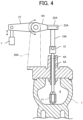
- FIG. 4 is a cross-sectional view taken along a cross-section IV-IV in FIG. 1 .
- FIG. 5 is a cross-sectional view depicting a structure for coupling a connecting member to a lever in the first embodiment of the present invention.
- FIG. 6 is a cross-sectional view depicting a structure for coupling a connecting member to a lever in a second embodiment of the present invention.
- FIG. 7 is a cross-sectional view depicting a structure for coupling a connecting member to a lever in a third embodiment of the present invention.
- FIG. 1 is a perspective view depicting the structure of a steam control valve in the present embodiment, and some sections thereof are omitted in the figure for convenience purposes.
- FIG. 2 is a cross-sectional view taken along a cross-section II-II in FIG. 1
- FIG. 3 is a partial enlarged cross-sectional view taken at a portion III in FIG. 2
- FIG. 4 is a cross-sectional view taken along a cross-section IV-IV in FIG. 1
- FIG. 5 is a cross-sectional view depicting a structure for coupling a connecting member to a lever in the present embodiment.
- the steam control valve includes: a plurality of valve seats 2 (four valve seats 2 in the present embodiment) that are formed inside a casing 1 ; a plurality of valve discs 3 (four valve discs 3 in the present embodiment) each of which is abuttable on a corresponding one of the plurality of valve seats 2 ; a pair of valve lifting rods 4 A and 4 B that are linked to the plurality of valve discs 3 , extend in a vertical direction, and penetrate the casing 1 ; a pair of cylindrical bushings 5 A and 5 B that are provided to the casing 1 , and respectively support the pair of valve lifting rods 4 A and 4 B slidably; a pair of levers 6 A and 6 B that are respectively linked to the upper ends of the pair of valve lifting rods 4 A and 4 B; and an actuator 7 (specifically, a hydraulic cylinder or a servomotor) that causes the pair of levers 6 A and 6 B to pivot.
- an actuator 7 specifically, a hydraulic cylinder or a servomotor
- a steam chest (valve chest) 8 is formed inside the casing 1 , and a steam inlet port 9 is formed at a side section of the casing 1 and communicates with the steam chest 8 . Thereby, high-temperature and high-pressure steam can be introduced into the steam chest 8 via the steam inlet port 9 .
- a plurality of steam supply ports 10 are formed at a bottom section of the casing 1 , and communicate with the steam chest 8 .
- Each of the plurality of valve seats 2 is formed at an opening edge section of a corresponding one of the plurality of steam supply ports 10 .
- the plurality of valve discs 3 which make the degrees of opening of the plurality of valve seats 2 variable, make it possible to adjust the supply rate of steam supplied from the steam chest 8 to a casing (not depicted) of the steam turbine.
- a valve lifting plate 11 is arranged in the steam chest 8 of the casing 1 .
- a plurality of through-holes 12 are formed through the valve lifting plate 11 , and each of a plurality of valve rods 13 is inserted to a corresponding one of the plurality of through-holes 12 .
- a valve disc 3 is provided on the bottom side of each valve rod 13 , and double nuts 14 are screwed onto a screw section on the top side of each valve rod 13 .
- the lower ends of the valve lifting rods 4 A and 4 B are coupled to the valve lifting plate 11 .
- the upper ends of the valve lifting rods 4 A and 4 B are coupled to each other via a coupling member 15 .
- male screw sections at the upper ends of the valve lifting rods 4 A and 4 B are screwed into female screw sections at both ends of the coupling member 15 .
- a guide rod 16 is arranged upright on the top side of the casing 1 , and is inserted into a through-hole at the middle of the coupling member 15 .
- a spring retaining member 17 is provided at the upper end of the guide rod 16 , and a spring 18 is provided between the spring retaining member 17 and the coupling member 15 .
- the spring 18 can urge the plurality of valve discs 3 downward via the coupling member 15 , the valve lifting rods 4 A and 4 B, and the valve lifting plate 11 .
- the upper end of the valve lifting rod 4 A is coupled to the lower end of a connecting member 19 A via the coupling member 15
- the upper end of the valve lifting rod 4 B is coupled with the lower end of a connecting member 19 B via the coupling member 15 .
- the lower end of the connecting member 19 A and the coupling member 15 are coupled to each other by a pin
- the lower end of the connecting member 19 B and the coupling member 15 are coupled to each other by a pin.
- One end of the lever 6 A is coupled to the upper end of the connecting member 19 A, and one end of the lever 6 B is coupled to the upper end of the connecting member 19 B.
- the other ends of the levers 6 A and 6 B are supported by brackets 20 A and 20 B, respectively, of the casing 1 rotatably.
- the other ends of the levers 6 A and 6 B are linked to the actuator 7 via link members 21 .
- a significant feature of the present embodiment is that a rectangular-parallelepiped box section 22 A having a downward-facing opening is provided on one end side of the lever 6 A, a rectangular-parallelepiped overhang section 23 A is provided on the upper end side of the connecting member 19 A, and the box section 22 A of the lever 6 A loosely fits the overhang section 23 A of the connecting member 19 A.
- the connecting member 19 A and the like are hung from the box section 22 A of the lever 6 A.
- the overall size of the internal space of the box section 22 A of the lever 6 A i.e.
- the size of the internal space in a vertical direction and a horizontal direction is larger than the overhang section 23 A of the connecting member 19 A by an amount corresponding to a predetermined value (e.g. approximately several millimeters) taking into consideration positional shifts of the bushing 5 A due to thermal expansion of the casing 1 .
- the opening of the box section 22 A of the lever 6 A is larger than the cross-section of the body of the connecting member 19 A by an amount corresponding to the predetermined value mentioned before, and additionally, is smaller than the cross-section of the overhang section 23 A of the connecting member 19 A by an amount corresponding to the predetermined value mentioned before.
- the inner surface of the box section 22 A of the lever 6 A supports the overhang section 23 A of the connecting member 19 A movably.
- a rectangular-parallelepiped box section 22 B having a downward-facing opening is provided on one end side of the lever 6 B
- a rectangular-parallelepiped overhang section 23 B is provided on the upper end side of the connecting member 19 B
- the box section 22 B of the lever 6 B loosely fits the overhang section 23 B of the connecting member 19 B.
- the connecting member 19 B and the like are hung from the box section 22 B of the lever 6 B.
- the overall size of the internal space of the box section 22 B of the lever 6 B i.e. the size of the internal space in a vertical direction and a horizontal direction
- the opening of the box section 22 B of the lever 6 B is larger than the cross-section of the body of the connecting member 19 B by an amount corresponding to the predetermined value mentioned before, and additionally, is smaller than the cross-section of the overhang section 23 B of the connecting member 19 B by an amount corresponding to the predetermined value mentioned before.
- the inner surface of the box section 22 B of the lever 6 B supports the overhang section 23 B of the connecting member 19 B movably.
- the degree of freedom of the arrangement of the valve lifting rods 4 A and 4 B can be enhanced as compared to a case where one end of the lever 6 A and the upper end of the connecting member 19 A are coupled to each other by a pin, and additionally, one end of the lever 6 B and the upper end of the connecting member 19 B are coupled to each other by a pin.
- FIG. 6 is a cross-sectional view depicting a structure for coupling a connecting member to a lever in the present embodiment.
- the steam control valve according to the present embodiment includes a plurality of steel balls 24 that are housed in the box section 22 A of the lever 6 A and support the overhang section 23 A of the connecting member 19 A movably, and a plurality of steel balls 24 that are housed in the box section 22 B of the lever 6 B and support the overhang section 23 B of the connecting member 19 B movably.
- FIG. 7 is a cross-sectional view depicting a structure for coupling a connecting member to a lever in the present embodiment.
- the steam control valve according to the present embodiment includes a sliding plate 25 that is housed in the box section 22 A of the lever 6 A and supports the overhang section 23 A of the connecting member 19 A movably, and a sliding plate 25 that is housed in the box section 22 B of the lever 6 B and supports the overhang section 23 B of the connecting member 19 B movably.
- the sliding plates 25 are formed such that the friction coefficient thereof becomes lower than the friction coefficients of the box sections 22 A and 22 B of the levers by using a preferable material therefor or subjecting them to a preferable surface treatment.
- box sections 22 A and 22 B of the levers, and the overhang sections 23 A and 23 B of the connecting members are formed into rectangular-parallelepiped shapes in example cases explained in the first to third embodiments, these are not the sole examples, and they may be formed into cubic shapes or spherical shapes, for example.
- the coupling member 15 and the connecting member 19 A are interposed between the valve lifting rod 4 A and the lever 6 A
- the coupling member 15 and the connecting member 19 B are interposed between the valve lifting rod 4 B and the lever 6 B
- the overhang sections 23 A and 23 B are provided to the connecting members 19 A and 19 B in example cases explained in the first to third embodiments, these are not the sole examples. That is, for example, the coupling member and the connecting members may not be interposed between the valve lifting rods and the levers, and the overhang sections may be provided to the valve lifting rods.
Landscapes
- Engineering & Computer Science (AREA)
- General Engineering & Computer Science (AREA)
- Mechanical Engineering (AREA)
- Lift Valve (AREA)
- Control Of Turbines (AREA)
- Mechanically-Actuated Valves (AREA)
Abstract
Description
- Patent Document 1: JP-2016-160973-A
-
- 2: Valve seat
- 3: Valve disc
- 4A, 4B: Valve lifting rod
- 5A, 5B: Bushing
- 6A, 6B: Lever
- 7: Actuator
- 19A, 19B: Connecting member
- 22A, 22B: Box section
- 23A, 23B: Overhang section
- 24: Steel ball
- 25: Sliding plate
Claims (5)
Applications Claiming Priority (2)
| Application Number | Priority Date | Filing Date | Title |
|---|---|---|---|
| JP2021-132406 | 2021-08-16 | ||
| JP2021132406A JP7328287B2 (en) | 2021-08-16 | 2021-08-16 | steam control valve |
Publications (2)
| Publication Number | Publication Date |
|---|---|
| US20230050574A1 US20230050574A1 (en) | 2023-02-16 |
| US11933422B2 true US11933422B2 (en) | 2024-03-19 |
Family
ID=85039796
Family Applications (1)
| Application Number | Title | Priority Date | Filing Date |
|---|---|---|---|
| US17/886,300 Active US11933422B2 (en) | 2021-08-16 | 2022-08-11 | Steam control valve |
Country Status (5)
| Country | Link |
|---|---|
| US (1) | US11933422B2 (en) |
| JP (1) | JP7328287B2 (en) |
| KR (1) | KR102779784B1 (en) |
| CN (1) | CN115704491A (en) |
| DE (1) | DE102022208353B4 (en) |
Citations (11)
| Publication number | Priority date | Publication date | Assignee | Title |
|---|---|---|---|---|
| JPS5037027A (en) | 1973-06-22 | 1975-04-07 | ||
| JPS5085827U (en) | 1973-12-08 | 1975-07-22 | ||
| JPS594581B2 (en) | 1974-10-29 | 1984-01-30 | 株式会社東芝 | Jiyoukikagenben |
| JPS599041Y2 (en) | 1972-07-24 | 1984-03-22 | キヤリア・コ−ポレイシヨン | Steam turbine speed regulating valve operating mechanism |
| US4456032A (en) | 1982-01-18 | 1984-06-26 | Elliott Turbomachinery Company, Inc. | Fluid admission valve structure |
| US5333989A (en) | 1992-12-23 | 1994-08-02 | General Electric Company | Electric actuators for steam turbine valves |
| US5354234A (en) * | 1992-06-24 | 1994-10-11 | Mercedes-Benz Ag | Actuating device for a motor vehicle regulating flap |
| US6425645B1 (en) * | 1999-03-18 | 2002-07-30 | Ntn Corporation | Thrust ball bearing |
| JP2012021568A (en) | 2010-07-14 | 2012-02-02 | Mitsubishi Heavy Ind Ltd | Horizontal valve |
| US20160069460A1 (en) * | 2009-09-02 | 2016-03-10 | Cameron International Corporation | Ball valve stem retaining system |
| JP2016160973A (en) | 2015-02-27 | 2016-09-05 | 三菱日立パワーシステムズ株式会社 | Valve drive device |
Family Cites Families (3)
| Publication number | Priority date | Publication date | Assignee | Title |
|---|---|---|---|---|
| CN203718036U (en) * | 2013-12-18 | 2014-07-16 | 诸暨市万盛机械有限公司 | Manual air control valve |
| JP2018172976A (en) * | 2017-03-31 | 2018-11-08 | 三菱重工コンプレッサ株式会社 | Steam valve |
| CN211009988U (en) * | 2019-06-11 | 2020-07-14 | 宛春辉 | Multi-way valve |
-
2021
- 2021-08-16 JP JP2021132406A patent/JP7328287B2/en active Active
-
2022
- 2022-08-08 CN CN202210942809.0A patent/CN115704491A/en active Pending
- 2022-08-10 KR KR1020220099761A patent/KR102779784B1/en active Active
- 2022-08-11 US US17/886,300 patent/US11933422B2/en active Active
- 2022-08-11 DE DE102022208353.9A patent/DE102022208353B4/en active Active
Patent Citations (12)
| Publication number | Priority date | Publication date | Assignee | Title |
|---|---|---|---|---|
| JPS599041Y2 (en) | 1972-07-24 | 1984-03-22 | キヤリア・コ−ポレイシヨン | Steam turbine speed regulating valve operating mechanism |
| JPS5037027A (en) | 1973-06-22 | 1975-04-07 | ||
| US3892382A (en) | 1973-06-22 | 1975-07-01 | Westinghouse Electric Corp | Holding arrangement for a main valve plug and a pilot valve plug |
| JPS5085827U (en) | 1973-12-08 | 1975-07-22 | ||
| JPS594581B2 (en) | 1974-10-29 | 1984-01-30 | 株式会社東芝 | Jiyoukikagenben |
| US4456032A (en) | 1982-01-18 | 1984-06-26 | Elliott Turbomachinery Company, Inc. | Fluid admission valve structure |
| US5354234A (en) * | 1992-06-24 | 1994-10-11 | Mercedes-Benz Ag | Actuating device for a motor vehicle regulating flap |
| US5333989A (en) | 1992-12-23 | 1994-08-02 | General Electric Company | Electric actuators for steam turbine valves |
| US6425645B1 (en) * | 1999-03-18 | 2002-07-30 | Ntn Corporation | Thrust ball bearing |
| US20160069460A1 (en) * | 2009-09-02 | 2016-03-10 | Cameron International Corporation | Ball valve stem retaining system |
| JP2012021568A (en) | 2010-07-14 | 2012-02-02 | Mitsubishi Heavy Ind Ltd | Horizontal valve |
| JP2016160973A (en) | 2015-02-27 | 2016-09-05 | 三菱日立パワーシステムズ株式会社 | Valve drive device |
Non-Patent Citations (1)
| Title |
|---|
| Office Action dated Jun. 20, 2023, issued in counterpart JP Application No. 2021-132406, with English trasnlation. (6 pages). |
Also Published As
| Publication number | Publication date |
|---|---|
| JP7328287B2 (en) | 2023-08-16 |
| KR102779784B1 (en) | 2025-03-12 |
| US20230050574A1 (en) | 2023-02-16 |
| CN115704491A (en) | 2023-02-17 |
| JP2023026945A (en) | 2023-03-01 |
| KR20230025758A (en) | 2023-02-23 |
| DE102022208353B4 (en) | 2025-07-17 |
| DE102022208353A1 (en) | 2023-02-16 |
Similar Documents
| Publication | Publication Date | Title |
|---|---|---|
| US11933422B2 (en) | Steam control valve | |
| CN102695996B (en) | Pressure reducing valves with multiple heads and seats | |
| JP6089098B2 (en) | Multi-valve steam valve and steam turbine | |
| KR20180059933A (en) | Steam valves and steam turbine systems | |
| KR101461912B1 (en) | Variable valve device that variably varies lift amount of valve | |
| EP2165097B1 (en) | 3-way high-pressure air operated valve | |
| KR101336392B1 (en) | Valve control system with inert rocker arm | |
| CN106812857A (en) | The damping valve arrangement that can be adjusted with orifice valve | |
| CN116507794A (en) | switchable rocker arm | |
| US4456032A (en) | Fluid admission valve structure | |
| CN105247435A (en) | Compact inverted pressure regulator for dispensing gas | |
| US20230049266A1 (en) | Steam valve | |
| KR102713990B1 (en) | Hydraulic damper with valve block | |
| JP2016114023A (en) | Steam valve device | |
| JPS599041Y2 (en) | Steam turbine speed regulating valve operating mechanism | |
| CN203604683U (en) | Mechanism for releasing pressure in central cavity | |
| KR101042327B1 (en) | Pilot Valves Using Hydraulic Actuators | |
| JPH10176502A (en) | Integral steam valve | |
| KR200444248Y1 (en) | Control Valve for Turbine Main Steam in Power Plant | |
| CN101135217B (en) | Floor door closer | |
| CN201198902Y (en) | Parallel double-valve petal gate valve | |
| DE202011101148U1 (en) | Device for forced ventilation of a seat | |
| SU1636651A1 (en) | Control device | |
| DE4228850A1 (en) | Exhaust gas recirculation valve - has return spring located in exhaust gas channel and coaxially to valve shaft, one end supporting itself and other end is supported on valve plate | |
| CN2818792Y (en) | Valve spring base frame of steam turbine |
Legal Events
| Date | Code | Title | Description |
|---|---|---|---|
| AS | Assignment |
Owner name: MITSUBISHI HEAVY INDUSTRIES, LTD., JAPAN Free format text: ASSIGNMENT OF ASSIGNORS INTEREST;ASSIGNOR:IGAWA, HIROSHI;REEL/FRAME:060789/0055 Effective date: 20220704 |
|
| FEPP | Fee payment procedure |
Free format text: ENTITY STATUS SET TO UNDISCOUNTED (ORIGINAL EVENT CODE: BIG.); ENTITY STATUS OF PATENT OWNER: LARGE ENTITY |
|
| STPP | Information on status: patent application and granting procedure in general |
Free format text: DOCKETED NEW CASE - READY FOR EXAMINATION |
|
| STPP | Information on status: patent application and granting procedure in general |
Free format text: NON FINAL ACTION MAILED |
|
| STPP | Information on status: patent application and granting procedure in general |
Free format text: RESPONSE TO NON-FINAL OFFICE ACTION ENTERED AND FORWARDED TO EXAMINER |
|
| STPP | Information on status: patent application and granting procedure in general |
Free format text: FINAL REJECTION MAILED |
|
| STPP | Information on status: patent application and granting procedure in general |
Free format text: DOCKETED NEW CASE - READY FOR EXAMINATION |
|
| STPP | Information on status: patent application and granting procedure in general |
Free format text: NOTICE OF ALLOWANCE MAILED -- APPLICATION RECEIVED IN OFFICE OF PUBLICATIONS |
|
| STPP | Information on status: patent application and granting procedure in general |
Free format text: PUBLICATIONS -- ISSUE FEE PAYMENT VERIFIED |
|
| STCF | Information on status: patent grant |
Free format text: PATENTED CASE |