US11932836B2 - Electric reaction measuring apparatus, electric reaction processing method, and recording medium - Google Patents
Electric reaction measuring apparatus, electric reaction processing method, and recording medium Download PDFInfo
- Publication number
- US11932836B2 US11932836B2 US16/920,356 US202016920356A US11932836B2 US 11932836 B2 US11932836 B2 US 11932836B2 US 202016920356 A US202016920356 A US 202016920356A US 11932836 B2 US11932836 B2 US 11932836B2
- Authority
- US
- United States
- Prior art keywords
- potential
- electrodes
- principal component
- measurement electrode
- measurement
- Prior art date
- Legal status (The legal status is an assumption and is not a legal conclusion. Google has not performed a legal analysis and makes no representation as to the accuracy of the status listed.)
- Active, expires
Links
- 238000006243 chemical reaction Methods 0.000 title claims abstract description 103
- 238000003672 processing method Methods 0.000 title description 5
- 238000005259 measurement Methods 0.000 claims abstract description 360
- 238000000513 principal component analysis Methods 0.000 claims abstract description 34
- 238000005192 partition Methods 0.000 claims description 68
- 238000000034 method Methods 0.000 claims description 36
- 230000000694 effects Effects 0.000 claims description 30
- 230000015654 memory Effects 0.000 claims description 29
- 230000008569 process Effects 0.000 claims description 21
- 239000000284 extract Substances 0.000 claims description 19
- 239000011159 matrix material Substances 0.000 claims description 10
- 230000002194 synthesizing effect Effects 0.000 claims description 9
- 210000004027 cell Anatomy 0.000 description 57
- 238000012545 processing Methods 0.000 description 34
- 238000012986 modification Methods 0.000 description 27
- 230000004048 modification Effects 0.000 description 27
- 238000005314 correlation function Methods 0.000 description 24
- 238000004364 calculation method Methods 0.000 description 16
- 239000000470 constituent Substances 0.000 description 14
- 230000006870 function Effects 0.000 description 14
- 239000002609 medium Substances 0.000 description 13
- 238000005516 engineering process Methods 0.000 description 12
- 239000007788 liquid Substances 0.000 description 12
- 230000001186 cumulative effect Effects 0.000 description 9
- 230000008901 benefit Effects 0.000 description 8
- 230000008859 change Effects 0.000 description 8
- 210000004748 cultured cell Anatomy 0.000 description 8
- 238000000926 separation method Methods 0.000 description 8
- 238000010586 diagram Methods 0.000 description 7
- 238000005070 sampling Methods 0.000 description 6
- 238000004891 communication Methods 0.000 description 4
- 238000004590 computer program Methods 0.000 description 4
- 238000000605 extraction Methods 0.000 description 4
- 238000003860 storage Methods 0.000 description 4
- 238000001514 detection method Methods 0.000 description 3
- 239000003814 drug Substances 0.000 description 3
- 238000010801 machine learning Methods 0.000 description 3
- 238000012258 culturing Methods 0.000 description 2
- 229940079593 drug Drugs 0.000 description 2
- 238000011156 evaluation Methods 0.000 description 2
- 230000000737 periodic effect Effects 0.000 description 2
- 230000010363 phase shift Effects 0.000 description 2
- 239000004065 semiconductor Substances 0.000 description 2
- 239000000126 substance Substances 0.000 description 2
- 230000003936 working memory Effects 0.000 description 2
- 238000012935 Averaging Methods 0.000 description 1
- 230000003321 amplification Effects 0.000 description 1
- 238000003491 array Methods 0.000 description 1
- 210000000227 basophil cell of anterior lobe of hypophysis Anatomy 0.000 description 1
- 239000012620 biological material Substances 0.000 description 1
- 230000005540 biological transmission Effects 0.000 description 1
- 238000004113 cell culture Methods 0.000 description 1
- 230000032823 cell division Effects 0.000 description 1
- 239000012777 electrically insulating material Substances 0.000 description 1
- 239000011521 glass Substances 0.000 description 1
- 239000001963 growth medium Substances 0.000 description 1
- 239000011796 hollow space material Substances 0.000 description 1
- 238000009413 insulation Methods 0.000 description 1
- 230000010354 integration Effects 0.000 description 1
- 238000004519 manufacturing process Methods 0.000 description 1
- 239000012528 membrane Substances 0.000 description 1
- 238000010295 mobile communication Methods 0.000 description 1
- 238000003199 nucleic acid amplification method Methods 0.000 description 1
- 230000010355 oscillation Effects 0.000 description 1
- 230000035479 physiological effects, processes and functions Effects 0.000 description 1
- 230000001172 regenerating effect Effects 0.000 description 1
- 239000011347 resin Substances 0.000 description 1
- 229920005989 resin Polymers 0.000 description 1
- 230000028327 secretion Effects 0.000 description 1
- 239000007787 solid Substances 0.000 description 1
- 230000002269 spontaneous effect Effects 0.000 description 1
- 238000007619 statistical method Methods 0.000 description 1
- 238000012360 testing method Methods 0.000 description 1
Images


Classifications
-
- C—CHEMISTRY; METALLURGY
- C12—BIOCHEMISTRY; BEER; SPIRITS; WINE; VINEGAR; MICROBIOLOGY; ENZYMOLOGY; MUTATION OR GENETIC ENGINEERING
- C12M—APPARATUS FOR ENZYMOLOGY OR MICROBIOLOGY; APPARATUS FOR CULTURING MICROORGANISMS FOR PRODUCING BIOMASS, FOR GROWING CELLS OR FOR OBTAINING FERMENTATION OR METABOLIC PRODUCTS, i.e. BIOREACTORS OR FERMENTERS
- C12M1/00—Apparatus for enzymology or microbiology
- C12M1/34—Measuring or testing with condition measuring or sensing means, e.g. colony counters
- C12M1/3407—Measure of electrical or magnetical factor
-
- C—CHEMISTRY; METALLURGY
- C12—BIOCHEMISTRY; BEER; SPIRITS; WINE; VINEGAR; MICROBIOLOGY; ENZYMOLOGY; MUTATION OR GENETIC ENGINEERING
- C12M—APPARATUS FOR ENZYMOLOGY OR MICROBIOLOGY; APPARATUS FOR CULTURING MICROORGANISMS FOR PRODUCING BIOMASS, FOR GROWING CELLS OR FOR OBTAINING FERMENTATION OR METABOLIC PRODUCTS, i.e. BIOREACTORS OR FERMENTERS
- C12M23/00—Constructional details, e.g. recesses, hinges
- C12M23/02—Form or structure of the vessel
- C12M23/12—Well or multiwell plates
-
- C—CHEMISTRY; METALLURGY
- C12—BIOCHEMISTRY; BEER; SPIRITS; WINE; VINEGAR; MICROBIOLOGY; ENZYMOLOGY; MUTATION OR GENETIC ENGINEERING
- C12M—APPARATUS FOR ENZYMOLOGY OR MICROBIOLOGY; APPARATUS FOR CULTURING MICROORGANISMS FOR PRODUCING BIOMASS, FOR GROWING CELLS OR FOR OBTAINING FERMENTATION OR METABOLIC PRODUCTS, i.e. BIOREACTORS OR FERMENTERS
- C12M41/00—Means for regulation, monitoring, measurement or control, e.g. flow regulation
- C12M41/46—Means for regulation, monitoring, measurement or control, e.g. flow regulation of cellular or enzymatic activity or functionality, e.g. cell viability
Definitions
- the present disclosure relates to an electric reaction measuring apparatus, an electric reaction processing method, and a recording medium.
- Patent Document 2 Japanese Patent No. 6072005 describes a method in which principal component analysis is used to extract an activity in a living body when measuring an electric reaction of the living body by using electrodes.
- One non-limiting and exemplary embodiment of the present disclosure provides an electric reaction measuring apparatus, an electric reaction processing method, and a recording medium each of which reduces noise common to measurement electrodes.
- the techniques disclosed here feature an electric reaction measuring apparatus measures a potential of each of measurement electrodes, which are respectively disposed in chambers in a culture vessel, with respect to at least one reference electrode.
- the electric reaction measuring apparatus includes at least one control circuit.
- a measurement object is disposed in each of the chambers.
- the at least one control circuit calculates at least one principal component for each of the measurement electrodes by performing principal component analysis of the potential of each of the measurement electrodes; estimates, for each of the measurement electrodes, a potential corresponding to the principal component from the principal component of the measurement electrode, and synthesizes the estimated potential; subtracts the synthesized potential of the measurement electrode from a potential measured at the measurement electrode; and outputs a potential after subtraction.
- the electric reaction measuring apparatus With the electric reaction measuring apparatus, the electric reaction measuring method, and the recording medium according to the present disclosure, it is possible to reduce noise common to measurement electrodes.
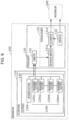
- FIG. 1 is a block diagram illustrating an example of the functional configuration of an electric reaction measuring apparatus according to a first embodiment
- FIG. 2 is a schematic perspective view illustrating an example of the configuration of the electric reaction measuring apparatus according to the first embodiment
- FIG. 3 is a schematic perspective view illustrating an example of the configuration of a culture vessel in FIG. 2 ;
- FIG. 4 A is a schematic plan view illustrating an example of the configuration of a reference electrode and measurement electrodes in the culture vessel in FIG. 3 ;
- FIG. 4 B is a schematic sectional side view taken along line IVB-IVB in FIG. 4 A ;
- FIG. 4 C illustrates a case where the liquid surface of a culture solution is held at a height that exceeds the height of a partition wall
- FIG. 4 D illustrates a case where the liquid surface of the culture solution is held at a height that does not exceed the height of the partition wall
- FIG. 5 is a schematic plan view illustrating an example of the configuration of a potential meter of a measuring unit in FIG. 1 ;
- FIG. 6 illustrates an example of contents stored in a memory of a processing unit in FIG. 1 ;
- FIG. 7 A illustrates an example of a process through which a signal processor of the processing unit in FIG. 1 processes a potential waveform
- FIG. 7 B illustrates an example of a process through which the signal processor of the processing unit in FIG. 1 processes a potential waveform
- FIG. 7 C illustrates an example of a process through which the signal processor of the processing unit in FIG. 1 processes a potential waveform
- FIG. 8 is a flowchart illustrating an example of an operation performed by the electric reaction measuring apparatus according to the first embodiment
- FIG. 9 is a block diagram illustrating an example of the hardware configuration of a potential acquirer in FIG. 1 ;
- FIG. 10 is a flowchart illustrating an example of the details of step S 1100 in FIG. 8 ;
- FIG. 11 A is a schematic plan view, similar to FIG. 4 A , illustrating electrodes of an electric reaction measuring apparatus according to a first modification of the first embodiment
- FIG. 11 B is a schematic sectional side view taken along line XIB-XIB in FIG. 11 A ;
- FIG. 12 A is a schematic plan view, similar to FIG. 4 A , illustrating electrodes of an electric reaction measuring apparatus according to a second modification of the first embodiment
- FIG. 12 B is a schematic sectional side view taken along line XIIB-XIIB in FIG. 12 A ;
- FIG. 13 is a block diagram illustrating an example of the functional configuration of a signal processor of an electric reaction measuring apparatus according to a second embodiment
- FIG. 14 is a flowchart illustrating an example of an operation performed by the electric reaction measuring apparatus according to the second embodiment
- FIG. 15 A illustrates an example of some of calculation results obtained by a correlation function processor of the electric reaction measuring apparatus according to the second embodiment
- FIG. 15 B illustrates an example of some of calculation results obtained by the correlation function processor of the electric reaction measuring apparatus according to the second embodiment
- FIG. 16 is a flowchart illustrating an example of the details of step S 2300 in FIG. 14 ;
- FIG. 17 is a flowchart illustrating an example of the details of step S 2400 in FIG. 14 ;
- FIG. 18 illustrates an example of some of calculation results obtained by a grouping processor of the electric reaction measuring apparatus according to the second embodiment.
- the inventors related to the present disclosure have found the following.
- the inventors examined technologies for non-invasively evaluating the activity of a cultured cell or a cultured tissue.
- the inventors focused on and examined technologies that use an electrical reaction of a cell or the like to evaluate various activities of the cell or the like.
- existing technologies such as those described in Patent Documents 1 and 2 and Non-Patent Document 1
- electric reactions of multiple cells or tissues may be reflected on a measurement result of measuring an electric reaction obtained by using a measurement electrode that is in contact with a cell or tissue.
- a measurement result of measuring an electric reaction at each measurement electrode may include a common noise and a common signal.
- the measurement result obtained at each measurement electrode cannot accurately represent an electric reaction of a cell or the like that is in contact with the measurement electrode.
- the inventors examined technology for reducing noise common to measurement electrodes.
- the inventors examined technology that reduces noise by using the shape of a culture vessel for culturing cells or tissues, the disposition of electrodes, and a statistical method.
- the inventors have found that noise can be reduced by disposing a measurement electrode in each of chambers, such as wells, of a culture vessel; measuring time-series data of potentials measured for a cultured cell or tissue in each chamber at each measurement electrode; extracting a component common to the measurement electrodes by using principal component analysis; and obtaining the remainder of a principal component for each measurement electrode.
- the inventors have devised the following technology.
- An electric reaction measuring apparatus measures a potential of each of measurement electrodes, which are respectively disposed in chambers in a culture vessel, with respect to at least one reference electrode.
- the electric reaction measuring apparatus includes at least one control circuit.
- a measurement object is disposed in each of the chambers.
- the at least one control circuit calculates at least one principal component for each of the measurement electrodes by performing principal component analysis of the potential of each of the measurement electrodes; estimates, for each of the measurement electrodes, a potential corresponding to the principal component from the principal component of the measurement electrode, and synthesizes the estimated potential; subtracts the synthesized potential of the measurement electrode from a potential measured at the measurement electrode; and outputs a potential after subtraction.
- a potential obtained by synthesizing the potential corresponding to a principal component estimated from a principal component coefficient and a principal component score of a measurement electrode is capable of representing noise at the measurement electrode.
- the noise which is estimated from the principal component coefficient and the principal component score, takes into consideration the features characteristic to the measurement electrode, such as the position relative to the reference electrode, and is a noise common to the measurement electrodes.
- a potential that is obtained by subtracting the noise from a potential measured at a measurement electrode is a potential from which a noise common to the measurement electrodes is effectively reduced.
- the electric reaction measuring apparatus can reduce, at each measurement electrode, noise common to the measurement electrodes and can extract a component that is recorded specifically at each measurement electrode. Further, the electric reaction measuring apparatus can extract and reduce noise that has been mixed into the measurement electrodes from one noise source, and can accurately extract an electric reaction derived from a measurement object that differs between measurement electrodes.
- An electric reaction measuring apparatus may further include the measurement electrodes and the at least one reference electrode.
- An electric reaction measuring apparatus may further include a partition wall that electrically separates the chambers from each other.
- the partition wall can suppress influence of the potential of a measurement electrode on the potential of another measurement electrode.
- the detection accuracy of the potential at each measurement electrode is improved, and electric reaction measuring apparatus can output a processing result with high accuracy.
- the measurement electrodes are disposed inside of the partition wall surrounding the chambers, and the reference electrode is disposed on the partition wall.
- the at least one control circuit calculates, for each of the at least one principal component, a contribution ratio of the principal component to a variance of all measured potentials; extracts, from the at least one principal component, some of the at least one principal component in descending order of the contribution ratio; and synthesizes, for each of the extracted principal components, potentials corresponding to the extracted principal components.
- a synthesized potential synthesized from potentials corresponding to principal components extracted in descending order of contribution ratio can effectively represent noise feature. Thus, it is possible to remove noise with high accuracy.
- the at least one control circuit calculates at least two principal components for each of the measurement electrodes; calculates, regarding the potentials corresponding to the principal components, a correlation coefficient of the potentials corresponding to two of the principal components; groups the two principal components whose correlation coefficient is greater than or equal to a predetermined value into one group; calculates, as a contribution ratio of the group, a sum of contribution ratios of all of the principal components included in the group; extracts, regarding the contribution ratio of the group and the contribution ratios of the principal components that are not included in the group, the group and the principal components that are not included in the group in descending order of the contribution ratio; estimates a sum of potentials corresponding to the principal components that are included in the extracted group and in the extracted principal components that are not included in the group; and subtracts the sum of the potentials from the potential measured at the measurement electrode.
- principal components included in the extracted group have a high correlation coefficient and are similar to each other.
- the sum of potentials which are composed of potentials corresponding to principal components whose contribution ratios are high, includes potentials corresponding to similar principal components.
- a potential corresponding to a principal component whose contribution ratio is low due to phase shift and that may be processed as a noise is included in the sum of potentials together with potentials corresponding to similar principal components, and is subtracted, that is, removed from the potential measured at a measurement electrode.
- An electric reaction processing method is a method of processing a potential of each of measurement electrodes, which are respectively disposed in chambers in a culture vessel in each of which a measurement object is disposed, with respect to at least one reference electrode.
- the method includes: acquiring the potential of each of the measurement electrodes with respect to the at least one reference electrode; calculating at least one principal component for each of the measurement electrodes by performing principal component analysis of the potential of each of the measurement electrodes; estimating, for each of the measurement electrodes, a potential corresponding to the principal component from the principal component of the measurement electrode, and synthesizing the estimated potential; subtracting the synthesized potential of each of the measurement electrodes from the potential acquired for the measurement electrode; and outputting a potential after subtraction.
- a non-transitory computer-readable recording medium causes a computer to execute a process.
- the process includes: acquiring a potential between each of measurement electrodes, which are respectively disposed in chambers in a culture vessel in each of which a measurement object is disposed, and at least one reference electrode; calculating at least one principal component for each of the measurement electrodes by performing principal component analysis of the potential for each of the measurement electrodes; estimating, for each of the measurement electrodes, a potential corresponding to the principal component from the principal component of the measurement electrode, and synthesizing the estimated potential; subtracting the synthesized potential of the measurement electrode from the potential acquired for the measurement electrode; and outputting a potential after subtraction.
- the apparatus may be constituted by one or more apparatuses. When the apparatus is constituted by two or more apparatuses, the two or more apparatuses may be disposed in one unit or may be disposed in two or more separate units. In the present specification and the claims, the term “apparatus” may mean not only one apparatus but also a system including multiple apparatuses.
- the electric reaction measuring apparatus 1 includes measurement electrodes that are electrically separated from each other by a partition wall, a culture vessel including at least one reference electrode, a potential meter including a potential acquirer and a controller, and a processing unit including a memory and a signal processor.
- the potential meter acquires the potentials of each of the measurement electrodes and the reference electrode of the culture vessel.
- the potential meter may acquire the potentials of the measurement electrodes with respect to the ground potential.
- the potential meter may acquire the potential of the reference electrode with respect to the ground potential.
- the processing unit extracts a time-varying component of a potential difference that is common to the potential differences of the measurement electrodes by using principal component analysis.
- the processing unit removes the extracted time-varying component of the potential difference as noise from the time waveform of the potential difference of each measurement electrode, thereby reducing noise included in the potential difference of each measurement electrode.
- potential difference between the potential of the measurement electrode and the potential of the reference electrode may be referred to simply as “potential”.
- the time waveform of a potential difference may be referred to as “potential waveform”.
- FIG. 1 is a block diagram illustrating an example of the functional configuration of the electric reaction measuring apparatus 1 according to the first embodiment.
- FIG. 2 is a schematic perspective view illustrating an example of the configuration of the electric reaction measuring apparatus 1 according to the first embodiment.
- the electric reaction measuring apparatus 1 includes a measuring unit 100 and a processing unit 200 .
- the processing unit 200 processes data of electric signals measured by the measuring unit 100 .
- the measuring unit 100 includes a culture vessel 110 , an electrode 120 in the culture vessel 110 , and a potential meter 130 .
- the processing unit 200 includes a memory 210 , a signal processor 220 , and an output unit 230 .
- the configuration of the measuring unit 100 will be described.
- the measuring unit 100 outputs, to the processing unit 200 , change in potential due to an electrical reaction of an object in the culture vessel 110 .
- the object include a biological material such as a cell or tissue. Although this is not a limitation, in the present embodiment, it is assumed that the object is a cultured cell or a cultured tissue cultured in the culture vessel 110 .
- the terms “cell” and “cultured cell” include the meaning of a single cell and multiple cells such as a cell cluster.
- FIG. 3 is a schematic top perspective view illustrating an example of the configuration of the culture vessel 110 in FIG. 2 .
- FIG. 4 A is a schematic plan view illustrating an example of the configuration of a reference electrode 120 a and measurement electrodes 120 b in the culture vessel 110 in FIG. 3 .
- FIG. 4 B is a schematic sectional side view taken along line IVB-IVB in FIG. 4 A .
- the culture vessel 110 is a vessel for culturing cells and tissues.
- the culture vessel 110 holds a culture solution including cells or tissues.
- the culture vessel 110 is a culture dish having a cylindrical shape with a bottom, which is called a Petri dish.
- the culture vessel 110 may be a culture plate or a culture flask.
- the culture vessel 110 includes a partition member 140 that is disposed on a bottom wall 110 a and that has chambers 140 b .
- the partition member 140 has a partition wall 140 a extending in a lattice shape, and the partition wall 140 a separates the chambers 140 b from each other.
- the partition wall 140 a is disposed so as to surround each chamber 140 b .
- the chamber 140 b is a rectangular-parallelepiped hollow space. Since the chamber 140 b is also called a “well”, in the present specification and in the claims, the chamber 140 b may be also referred to as a “well”. Cultured cells or tissues are disposed in the wells 140 b.
- Each well 140 b opens downward toward the bottom wall 110 a and opens upward in the opposite direction.
- Each well 140 b is physically and electrically separated from another well 140 b that is laterally adjacent thereto.
- the partition member 140 is made of an electrically insulating material such as resin or glass. Therefore, electrical separation between adjacent wells 140 b is increased by the partition wall 140 a . That is, an electrical reaction is not easily transmitted between adjacent wells 140 b .
- the partition member 140 which has a plate-like shape in its entirety, is also called a well plate.
- the well 140 b has a rectangular shape in plan view as seen from above.
- the well 140 b may have any appropriate shape, such as a circular shape, an elliptical shape, or a polygonal shape.
- the culture vessel 110 and the partition member 140 are replaced every time cells or tissues have been cultured.
- the culture vessel 110 and the partition member 140 may be independent members or may be an integrated member.
- the electrode 120 is composed of at least one reference electrode 120 a and measurement electrodes 120 b 1 , 120 b 2 , 120 bk , 120 bm (where m is greater than or equal to 2).
- the measurement electrodes 120 b 1 to 120 bm are connected to circuits that differ from each other. That is, signals of the measurement electrodes 120 b 1 to 120 bm are independently output to a connector 132 of the potential meter 130 .
- the measurement electrodes 120 b 1 to 120 bm will be also referred to as “measurement electrodes 120 b ”.
- one reference electrode 120 a is disposed on the bottom wall 110 a of the culture vessel 110 .
- the one reference electrode 120 a may be a single electrode or may be a group of electrodes.
- a potential waveform may be acquired by using, as the reference potential, one potential that is obtained by electrically connecting the reference electrodes.
- a potential waveform may be acquired by using, as the reference potential, the average of the potentials of the reference electrodes.
- the reference electrode 120 a extends through the bottom wall 110 a , is exposed in the culture vessel 110 , and is in contact with the culture solution in the culture vessel 110 .
- the reference electrode 120 a is disposed outside of the partition member 140 and is separated from any of the wells 140 b by the partition wall 140 a .
- the reference electrode 120 a does not make contact with cells or tissues in the wells 140 b .
- the reference electrode 120 a need only to be disposed so as to be in contact with the culture solution. Therefore, the reference electrode 120 a may be disposed, instead of a position on the bottom wall 110 a , at any position in the culture vessel 110 that is in contact with the culture solution and that is outside of the partition member 140 , such as a position on a side wall.
- the measurement electrodes 120 b are disposed on the bottom wall 110 a of the culture vessel 110 .
- Each measurement electrode 120 b is disposed in the well 140 b .
- one measurement electrode 120 b is disposed in one well 140 b .
- Each measurement electrode 120 b extends through the bottom wall 110 a and is exposed in the well 140 b .
- Each measurement electrode 120 b is in contact with the culture solution in the well 140 b , and is in contact with or in proximity to a cell or tissue in the well 140 b .
- the measurement electrode 120 b may be disposed, instead of a position on the bottom wall 110 a , at any position that is in contact with or in proximity to a cell or tissue in the well 140 b and that is in contact with the culture solution.
- the measurement electrodes 120 b and the reference electrode 120 a each need only be disposed at a position in contact with a culture medium.
- Wires such as lead wires, extending from the reference electrode 120 a and each measurement electrode 120 b are connected to the connector 132 of the potential meter 130 .
- Each wire may be embedded in the bottom wall 110 a of the culture vessel 110 . In this case, when the culture vessel 110 is placed on the connectors 132 , the reference electrode 120 a and each measurement electrode 120 b are electrically connected to the connectors 132 .
- the culture solution is held in the culture vessel 110 .
- the liquid surface 150 of the culture solution may be held at a height exceeding the height of the partition wall 140 a as illustrated in FIG. 4 C , or the liquid surface 150 of the culture solution may be held at a height that does not exceed the height of the partition wall 140 a as illustrated in FIG. 4 D .
- the measurement electrodes 120 b and the reference electrode 120 a are electrically connected to each other through the culture solution.
- electrical connection through the culture solution which circumvents the partition wall 140 a having insulating properties, can increase electrical separation between the electrodes by increasing the distance between the electrodes.
- a cell or tissue is disposed so as to be in contact with or in proximity to the measurement electrode 120 b .
- the distance between the cell or the tissue and a measurement electrode 120 b in another well or the reference electrode 120 a is sufficiently large, and electrical separation is sufficiently large. Therefore, the probability that an electrical reaction of the cell or the tissue influences potential detection at the measurement electrode 120 b in the other well or potential detection at the reference electrode 120 a is negligibly low.
- the measurement electrodes 120 b and the reference electrode 120 a are not electrically connected to each other, and electrical separation is sufficiently large.
- FIG. 5 is a schematic plan view illustrating an example of the configuration of the potential meter 130 of the measuring unit 100 in FIG. 1 .
- the potential meter 130 acquires the potential waveform of cells or tissues that are in contact with or in proximity to the measurement electrodes 120 b .
- the potential meter 130 includes a potential acquirer 131 , the connector 132 , and a controller 133 .
- the potential meter 130 constitutes the entirety or a part of a connector device 300 having a plate-like shape as illustrated in FIG. 2 .
- the connector device 300 is configured so that the culture vessel 110 can be placed on a placement surface thereof, and is connected to a computer 400 via wired or wireless communication.
- the processing unit 200 constitutes the entirety or a part of the computer 400 .
- the connector 132 includes terminals 132 a disposed on the placement surface of the connector device 300 .
- the connector 132 is composed of the terminals 132 a and a circuit connected to the terminals 132 a .
- the terminals 132 a are in contact with and electrically connected to wires such as lead wires extending from the reference electrode 120 a and the measurement electrodes 120 b of the culture vessel 110 placed on the placement surface of the connector device 300 .
- the connector 132 connects the wires, which are respectively connected to the reference electrode 120 a and the measurement electrodes 120 b , to the circuit in the connector device 300 .
- the connector 132 connects the reference electrode 120 a and the measurement electrodes 120 b to the inside of the potential meter 130 , that is, to the potential acquirer 131 by enabling the terminals 132 a of the connector 132 to be in contact with the wires.
- the potential acquirer 131 acquires the potential difference between the potentials of each measurement electrode 120 b of the culture vessel 110 , which is connected to the circuit via the connector 132 , and the potential of the reference electrode 120 a while performing sampling at a predetermined sampling frequency and digitizing the sampled data.
- the potential difference between the measurement electrode 120 b and the reference electrode 120 a may be referred to as “the potential of the measurement electrode 120 b”.
- a cell or tissue that is in contact with or in proximity to the measurement electrode 120 b performs an activity such as: an activity that is caused by change in culture environment, such as a chemical change due to addition of a drug, an electric stimulus, or vibration; or an autonomous activity of the cell or tissue.
- Examples of the autonomous activity include cell division, spontaneous electric discharge, and secretion of a chemical substance.
- the potential acquirer 131 acquires change in the potential difference between the potential of the measurement electrode 120 b and the potential of the reference electrode 120 a , which occurs due to the activity.
- the measurement electrodes 120 b are electrically separated from each other by the partition wall 140 a of the partition member 140 , and the wires extending from the measurement electrodes 120 b are insulated from each other. Therefore, change in potential in each well 140 b is not easily transmitted to another well 140 b and is acquired by the potential acquirer 131 in a state in which an influence on another well 140 b and influence from another well 140 b are suppressed.
- the controller 133 controls the operation of the potential acquirer 131 . Moreover, the controller 133 outputs, to the processing unit 200 , the value of the potential of each measurement electrode 120 b with respect to the potential of the reference electrode at each sampling point, which has been acquired by the potential acquirer 131 , and stores the value in the memory 210 of the processing unit 200 .
- the potential acquirer 131 and the controller 133 may be implemented in a computer system (not shown) that includes a processor such as a central processing unit (CPU) or a digital signal processor (DSP), memories such as a random-access memory (RAM) and a read-only memory (ROM), and the like. Some or all functions of the potential acquirer 131 and the controller 133 may be performed by executing a program, which is stored in the ROM, by using the RAM as a working memory. Some or all functions of the potential acquirer 131 and the controller 133 may be performed by a dedicated hardware circuit, such as an electronic circuit or an integrated circuit. Some or all functions of the potential acquirer 131 and the controller 133 may be configured as a combination of the software function and the hardware circuit
- the processing unit 200 removes noise common to the measurement electrodes 120 b from a measurement result of measuring a potential with respect to the potential of the reference electrode, which is output from the potential meter 130 , and outputs a result after noise removal.
- the processing unit 200 constitutes, for example, a part or the entirety of the computer 400 illustrated in FIG. 2 .
- the processing unit 200 includes the memory 210 , the signal processor 220 , and the output unit 230 .
- the processing unit 200 is an example of a control circuit.
- the memory 210 can store and retrieve various information items.
- the memory 210 is constituted, for example, by storage devices such as a semiconductor memory such as a ROM, a RAM, or a flash memory; a hard disk drive; and a solid state drive (SSD).
- the memory 210 stores information that is output from the potential meter 130 to the processing unit 200 .
- the potential meter 130 outputs, to the memory 210 , the value of a potential with respect to the potential of the reference electrode, which is obtained by sampling the potential of each measurement electrode 120 b acquired by the potential acquirer 131 at each sampling point, that is, at each predetermined time.
- the memory 210 stores the value of the potential of each measurement electrode 120 b with respect to the potential of the reference electrode at each predetermined time, in association with a measurement time.
- FIG. 6 illustrates an example of contents stored in the memory 210 of the processing unit 200 in FIG. 1 .
- the value of a potential with respect to the potential of the reference electrode, which is measured at each measurement electrode 120 b at each time, is stored in the memory 210 .
- Potentials handled by the signal processor 220 and the output unit 230 are potentials with respect to the potential of the reference electrode.
- the signal processor 220 removes noise common to the measurement electrodes 120 b by performing principal component analysis of a potential waveform composed of the value of the potential of each measurement electrode 120 b stored in the memory 210 and the time axis.
- the detailed configuration of the signal processor 220 will be described below.
- Constituent elements of the signal processor 220 may be implemented in a computer system (not shown) that includes a processor, such as a CPU or a DSP, memories such as a RAM and a ROM, and the like. Some or all functions of each constituent element may be performed by the CPU or the DSP by executing programs, which are stored in the ROM, by using the RAM as a working memory.
- each constituent element may be performed by a dedicated hardware circuit, such as an electronic circuit or an integrated circuit. Some or all functions of each constituent element may be configured as a combination of the software function and the hardware circuit.
- the program may be stored beforehand in each constituent element, or may be provided as an application through communication via a communication network such as the Internet, communication in accordance with a mobile communication standard, another wireless network, a wired network, or broadcasting.
- the output unit 230 outputs a signal of a potential waveform of each measurement electrode 120 b from which noise has been removed by the signal processor 220 .
- An example of the output signal is data of the potential waveform of each measurement electrode 120 b represented as a numeric series.
- the output unit 230 may output and store the output signal in a storage medium (not shown).
- the output unit 230 may output the output signal to a display or a printer to cause display to display the output signal or to cause the printer to print the output signal on a print medium such as paper.
- the output unit 230 may output the output signal to software or a circuit that performs a determination process on the output signal. An example of the determination is determination of whether the activity of a cell or tissue is good, which is performed based on the potential waveform.
- the output unit 230 may be constituted by a circuit that outputs a signal to an output target.
- the signal processor 220 regards the potential waveforms of the measurement electrodes 120 b as a data series of variables at each sample point.
- the data series includes variables X1 to Xm, and the variables X1 to Xm are respectively potentials in the potential waveforms of the measurement electrodes 120 b 1 to 120 bm at the sample point of the same time.
- a potential at a sample point is, for example, a potential measured at each predetermined time.
- X11 is the potential of the measurement electrode 120 b 1 measured at a time t
- X1l is the potential of the measurement electrode 120 b 1 measured at a time t+(l ⁇ 1) ⁇ a
- X1p is the potential of the measurement electrode 120 b 1 measured at a time t+(p ⁇ 1) ⁇ a; . . .
- Xk1 is the potential of the measurement electrode 120 bk measured at a time t
- Xkl is the potential of the measurement electrode 120 bk measured at a time t+(l ⁇ 1) ⁇ a
- Xkp is the potential of the measurement electrode 120 bk measured at a time t+(p ⁇ 1) ⁇ a
- Xm1 is the potential of the measurement electrode 120 bm measured at a time t
- Xml is the potential of the measurement electrode 120 bm measured at a time t+(l ⁇ 1) ⁇ a
- Xmp is the potential of the measurement electrode 120 bm measured at a time t+(p ⁇ 1) ⁇ a.
- the signal processor 220 extracts a component common to the potential waveforms of the measurement electrodes 120 b 1 to 120 bm as a principal component by performing principal component analysis of data series composed of the variables X1 to Xm.
- the signal processor 220 regards the principal component common to the measurement electrodes 120 b 1 to 120 bm as noise.
- the signal processor 220 regards potentials respectively recorded at the measurement electrodes 120 b 1 to 120 bm as respective data series, performs principal component analysis of data including the data series, and thus extracts and calculates at least one principal component for each measurement electrode 120 b 1 to 120 bm . Moreover, for each of the measurement electrode 120 b 1 to 120 bm , the signal processor 220 estimates, from the principal component of the measurement electrode, a potential corresponding to the principal component.
- principal component coefficients coefficients for the variables X1 to Xm
- the signal processor 220 synthesizes the estimated potential of each measurement electrode 120 bk due to the principal component, and subtracts the synthesized potential of the measurement electrode 120 bk from the potential measured at the measurement electrode 120 bk .
- the signal processor 220 outputs the remainder of subtraction, which has been calculated for each measurement electrode 120 bk , as a noise removal result of the measurement electrode 120 bk .
- the signal processor 220 includes a principal component analyzer 221 , a principal component synthesizer 222 , and a common noise remover 223 .
- the principal component analyzer 221 continues extraction of principal components until a predetermined number of principal components are extracted. Alternatively, the principal component analyzer 221 continues extraction of principal components until the contribution ratio, to the total variance, of the extracted principal components, that is, the cumulative contribution ratio of the extracted principal components exceeds a predetermined value. That is, the principal component analyzer 221 calculates, for each principal component, the contribution ratio of the principal component to the variance of all measured potentials, and extracts some of the principal components in descending order of the contribution ratio.
- the term “contribution ratio” of a principal component refers to the proportion, in the entire information of data, of information represented by the eigenvalue of the principal component, and is the ratio of the eigenvalue to the total variance.
- the cumulative contribution ratio is a value calculated by adding the contribution ratios of the principal components in descending order. An example of the value of the predetermined cumulative contribution ratio is 70%.
- the principal component analyzer 221 outputs, to the principal component synthesizer 222 , the principal component coefficient and the principal component score of each of the extracted principal components.
- the total variance is the variance of data measured at all measurement electrodes used in principal component analysis.
- the number of measurement electrodes corresponds to the dimension of data in principal component analysis. Therefore, for example, in principal component analysis, the number of principal components that can be obtained is the same as the number of the variables X1 to Xm of the data series.
- the first principal component is a linear combination of variables that has the largest variance among all linear combinations of the variables.
- the second principal component is a linear combination that is uncorrelated with the first principal component and that has the largest variance among the linear combinations.
- the third principal component and the following principal components are each a linear combination that is uncorrelated with the previous principal components and that has the largest variance among the linear combinations. That is, as linear combinations of variables, orthogonal components converted in descending order of variance are obtained as principal components.
- An eigenvalue obtained by principal component analysis is the variance of principal component.
- An eigenvector obtained by principal component analysis is a vector whose elements are principal component coefficients that are weights by which the variables X1 to Xm are multiplied when representing a principal component by using the variables X1 to Xm.
- a principal component score is the linear combination of the eigenvector and the variables X1 to Xm. Details of the principal component analysis will be described below.
- the principal component analysis may be performed as follows.
- the principal component analyzer 221 obtains an eigenvalue X1, an eigenvalue ⁇ 2, . . . , an eigenvalue Xm of the covariance matrix.
- the principal component analyzer 221 obtains, from the eigenvalues ⁇ 1, ⁇ 2, . . . , Xm, the eigenvector (u1 max1 u2 max1 . . . um max1 ) T of the largest eigenvalue ⁇ max1, the eigenvector (u1 max2 u2 max2 . . . um max2 ) T of the second largest eigenvalue ⁇ max2, . . . .
- the principal component analyzer 221 “continues extraction of principal components until the cumulative contribution ratio of the extracted principal components exceeds a predetermined value”.
- An example of this process is as follows.
- avg1 (X11+X21+X31)/3, which is the average of potentials at a time t
- avg2 (X12+X22+X32)/3, which is the average of potentials at a time t+a
- avg3 (X13+X23+X33)/3, which is the average of potentials at a time t+2a.
- the principal component analyzer 221 obtains a first principal component score z1 and a second principal component score z2. That is, the principal component analyzer 221 need not obtain a third principal component score z3, which uses elements of the eigenvector for the eigenvalue ⁇ 3.
- the synthesized waveform which is a potential waveform, differs between the measurement electrodes 120 bk .
- the synthesized waveform based on the principal components of each measurement electrode 120 bk represents a noise component that takes the influence of noise on the measurement electrode 120 bk into consideration, and is a noise component common to the measurement electrodes 120 b 1 to 120 bm .
- the noise component common to the measurement electrodes 120 b 1 to 120 bm can be obtained for each measurement electrode 120 bk while taking the influence of noise on the measurement electrode 120 bk into consideration.
- principal component coefficients of the first principal component are u11, u12, and u13.
- the variable Xk (1 ⁇ k ⁇ m, k: integer) is a time direction vector of potentials measured at the measurement electrode 120 bk (1 ⁇ k ⁇ m, k: integer).
- the principal component coefficient of the i-th principal component will be denoted by “ai”
- the principal component coefficient of the variable Xk will be denoted by “aik”.
- the principal component score of the i-th principal component will be denoted by “zi”.
- zi In calculation of the principal component score zi, as represented by expression (1) below, for each of extracted principal components, data composed of the coordinates values of the variables X1 to Xm at each sample point, which are disposed in an m-dimensional space having the elements of the vector of the variables X1 to Xm as coordinates, is converted into a value in a space having the principal components as coordinates.
- the coordinates composed of data (potentials) of the measurement electrodes 120 b 1 to 120 bm at a sample point l (1 ⁇ l ⁇ p, l: integer) are denoted by (X1l, X2l, X3l, . . . , Xkl, . . . , Xml).
- the total variance of data is the variance of the data at all sample points having coordinates (X1l, X2l, X3l, . . . Xkl, . . . , Xml) in the space having the elements of the vector of the variables X1 to Xm as coordinates.
- a data space is set by using the vector of variables X1 to Xm as orthogonal coordinates, and the variance of data is maximized by rotating the coordinate axes, that is, calculation is performed so as to extract axes that optimally explain the variation of the data.
- Contribution ratio to variance refers to the ratio of variance that can be explained by a principal component to the variation in the m-dimensional data space.
- a second synthesized waveform Yk which is a potential waveform obtained by synthesizing the 1st to n-th principal components (1 ⁇ i ⁇ n, i: integer, n ⁇ m) at the measurement electrode 120 bk , can be obtained by adding the first synthesized waveforms Ylk to Ynk.
- a value (potential) Ykl on the second synthesized waveform Yk at a sample point l is obtained by using expression (3) below.
- the value Ykl represents “noise” due to the 1st to n-th principal components at the sample point l.
- the second synthesized waveform Yk which is formed from the value Ykl at each sample point l, represents “noise” at the measurement electrode 120 bk due to the 1st to n-th principal components.
- the noise is a noise component common to the measurement electrodes 120 b 1 to 120 bm .
- the common noise remover 223 obtains, for each measurement electrode 120 bk , a remainder waveform by subtracting the synthesized waveform (the second synthesized waveform) of change in potential of the measurement electrode 120 bk due to the extracted principal components, which has been synthesized by the principal component synthesizer 222 , that is, noise from the measured potential waveform of the measurement electrode 120 bk .
- the remainder waveform represents a potential waveform after removal of noise at the measurement electrode 120 bk . If the number of principal components extracted by the principal component analyzer 221 is one, the principal component synthesizer 222 obtains the first synthesized waveform and need not obtain the second synthesized waveform.
- FIGS. 7 A to 7 C illustrate an example of a process through which the signal processor 220 of the processing unit 200 in FIG. 1 processes a potential waveform.
- FIGS. 7 A to 7 C illustrate processes through which potential waveforms of three measurement electrodes, among five measurement electrodes 120 bk to 120 bk+ 4 used for calculation, are processed.
- FIG. 7 A illustrates a process for the measurement electrode 120 bk
- FIG. 7 B illustrates a process for the measurement electrode 120 bk+ 1
- FIG. 7 C illustrates a process for the measurement electrode 120 bk+ 2.
- the vertical axis represents potential ( ⁇ V) and the horizontal axis represents time (seconds).
- an upper graph UG shows a potential waveform before being processed.
- a lower graph LG shows a potential waveform obtained as a result of removing the noise component shown in the middle graph MG from the potential waveform in the upper graph before being processed.
- the noise components shown in middle graphs MG which differ between measurement electrodes in size and in waveform, each include a pulse-shaped periodic component.
- the pulse frequency of the periodic component is 60 Hz, and the waveform of the pulse sharply varies.
- the lower graphs LG show gentle waveforms that differ between measurement electrodes, which are difficult to be discerned in the upper graphs UG.
- FIG. 8 is a flowchart illustrating an example of an operation performed by the electric reaction measuring apparatus 1 according to the first embodiment.
- Step S 1100 the measuring unit 100 simultaneously acquires the potentials of the measurement electrodes 120 b 1 to 120 bm and the potential of the reference electrode 120 a . Moreover, the measuring unit 100 acquires the difference between the potential of each of the measurement electrodes 120 b 1 to 120 bm and the potential of the reference electrode 120 a as the potential of each of the measurement electrodes 120 b 1 to 120 bm at predetermined time intervals. The measuring unit 100 stores, in the memory 210 of the processing unit 200 , the acquired potential and the acquired time in correspondence with each other for each of the measurement electrodes 120 b 1 to 120 bm . FIG. 6 shows an example of the contents stored in the memory 210 .
- Step S 1200 the principal component analyzer 221 of the processing unit 200 sets variables X1 to Xm for a potential waveform that is a time waveform representing the relationship between the potential and the time for each measurement electrode 120 b 1 to 120 bm stored in the memory 210 in step S 1100 . Moreover, the principal component analyzer 221 determines, for each of the variables X1 to Xm, potentials at predetermined measurement intervals or potentials at predetermined measurement times in the potential waveform corresponding to the variable as the observed value of the variable, that is, the data value. Thus, the variables X1 to Xm are respectively data series including the potentials of the measurement electrodes 120 b 1 to 120 bm as data values. The principal component analyzer 221 performs principal component analysis by using the variables X1 to Xm and the data series.
- the principal component analyzer 221 continues principal component analysis until a predetermined number of principal components are extracted or until principal components whose contribution ratios exceed a predetermined contribution ratio to the total variance are extracted. Calculation of the principal component analysis is performed by using a general calculation method. For example, the principal component analyzer 221 obtains the covariance matrix of potentials for the data series of the variables X1 to Xm of all measurement electrodes 120 b 1 to 120 bm , and further obtains the eigenvectors and the eigenvalues of the covariance matrix. Here, m eigenvalues and eigenvectors respectively corresponding to the m eigenvalues are calculated.
- the principal component analyzer 221 sorts the eigenvectors in descending order of eigenvalues, and regards the elements of the eigenvectors as the coefficient series of a principal component. For example, the elements of an eigenvector corresponding to the largest eigenvalue is the coefficient series of the first principal component, and the elements of an eigenvector corresponding to the k-th largest eigenvalue is the coefficient series of the k-th principal component.
- the principal component analyzer 221 When extracting a predetermined number of principal components, the principal component analyzer 221 extracts a predetermined number of principal components in descending order of eigenvalue. When the principal component analyzer 221 determines the number of principal components to be extracted based on the contribution ratios to the total variance, that is, the cumulative contribution ratio, the principal component analyzer 221 obtains the contribution ratios and the cumulative contribution ratio by using the eigenvalues, and extracts a number of principal components that provide the smallest cumulative contribution ratio that exceeds a predetermined cumulative contribution ratio. The principal component analyzer 221 regards the elements of an eigenvector corresponding to a principal component as a principal component coefficient.
- the principal component analyzer 221 maps individual data, that is, potential data at each sample point with each measurement electrode as an axis onto a principal component axis that is a directional axis of the eigenvector of the obtained principal component, and obtains a value at each sample point on the principal component axis as a principal component score.
- Step S 1300 For a predetermined number of principal components extracted in step S 1200 , the principal component synthesizer 222 obtains, for each measurement electrodes 120 b 1 to 120 bm , potentials due to the principal components for each measurement time, that is, for each sample point by using the principal component coefficients and the principal component scores, and synthesizes a noise waveform due to the extracted principal components. In synthesizing the potential waveform, potentials at the same sample point in each potential waveform are added.
- a potential generated by the principal components is regarded as a noise common to the measurement electrodes 120 b 1 to 120 bm , and the noise is subtracted from the observed value, and thereby noise included in the observed values is removed.
- the common noise remover 223 calculates, for each of the measurement electrodes 120 b 1 to 120 bm , a time waveform of potential composed of residues calculated at measurement intervals or at measurement times, and thus generates a potential waveform after noise removal at each of the measurement electrodes 120 b 1 to 120 bm.
- Step S 1500 The output unit 230 outputs the potential waveform after noise removal of each of the measurement electrodes 120 b 1 to 120 bm , which has been calculated by the common noise remover 223 in step S 1400 , as a numeric series in which a potential is paired with the time when the potential is measured.
- FIG. 9 is a block diagram illustrating an example of the hardware configuration of the potential acquirer 131 in FIG. 1 .
- the potential acquirer 131 is composed of a differential amplifier 131 a and an analog-to-digital (AD) converter 131 b.
- AD analog-to-digital
- the differential amplifier 131 a outputs the potential of each of the measurement electrodes 120 b 1 to 120 bm as the difference from the reference potential of the reference electrode 120 a by using the potential of the reference electrode 120 a as the reference potential.
- the AD converter 131 b converts an analog signal into a digital signal.
- the AD converter 131 b converts the potential, which is input thereto as an analog signal at predetermined time intervals, into a numeric value.
- the predetermined time interval is, for example, an interval corresponding to 20000 times per second, 0.5 milliseconds, or the like.
- the AD converter 131 b converts a potential into a numerical value in synchronism between the measurement electrodes 120 b 1 to 120 bm . That is, the AD converter 131 b converts potentials that are measured at the measurement electrodes 120 b 1 to 120 bm at the same time into numerical values.
- FIG. 10 is a flowchart illustrating an example of the operation of the potential meter 130 of the electric reaction measuring apparatus 1 according to the first embodiment.
- FIG. 10 is also a flowchart illustrating an example of the details of step S 1100 in FIG. 8 .
- Step S 1110 First, the differential amplifier 131 a simultaneously acquires the potentials of the measurement electrodes 120 b 1 to 120 bm and the potential of the reference electrode 120 a.
- the operation of the differential amplifier 131 a is also called “differential amplification”. As described above, signals output from the measurement electrodes 120 b 1 to 120 bm to the differential amplifier 131 a are independent from each other due to the insulation function of the partition member 140 and the like.
- Step S 1130 the AD converter 131 b acquires the potential difference between each of the measurement electrodes 120 b 1 to 120 bm and the reference electrode 120 a , which has been obtained by the differential amplifier 131 a in step S 1120 , at predetermined time intervals and converts the potential difference into a numeric value.
- the time interval may be determined by the controller 133 .
- the controller 133 may perform synchronization of the time interval or the time at which the potential is to be obtained, between the measurement electrodes 120 b 1 to 120 bm.
- Step S 1140 the AD converter 131 b outputs the potential difference of each of the measurement electrodes 120 b 1 to 120 bm , which has been converted into a numeric value in step S 1130 , to the memory 210 together with information about the time interval or the time when the potential was converted into a numeric value.
- the time interval or the time when the potential was converted into a numeric value may be regarded as the measurement interval or the measurement time of the potential.
- the measurement electrodes 120 b 1 to 120 bm are separated from each other in the culture vessel 110 by the partition wall 140 a of the partition member 140 .
- the electric reaction measuring apparatus 1 performs principal component analysis on potential waveforms simultaneously measured at the measurement electrodes 120 b 1 to 120 bm .
- the electric reaction measuring apparatus 1 regards a potential waveform that is extracted from principal components for each measurement electrode 120 b 1 to 120 bm as a noise common to the measurement electrodes, and subtracts the potential waveform of noise from the potential waveform measured at each of the measurement electrodes 120 b 1 to 120 bm . Accordingly, the electric reaction measuring apparatus 1 can measure an electric reaction that reflects the activity of a cell or tissue disposed at each of the measurement electrodes 120 b 1 to 120 bm independently for the cell or tissue and with high accuracy. Thus, it is possible to measure an electrical reaction due to the specific activity of a cell or tissue with higher accuracy, because noise from the outside of the cell or tissue, which influences measurement signals of the measurement electrodes 120 b 1 to 120 bm , is removed.
- a user can easily determine whether the activity of a cell or tissue is good, from the output result of the electric reaction measuring apparatus 1 using the electrical reaction.
- the electric reaction measuring apparatus 1 is applied to a technology for automatically determining, by machine learning, whether an activity of a cell or tissue is good based on an electric reaction of the cell or tissue, machine learning of an automatic determination process is facilitated, and it is possible to increase the determination accuracy.
- the electric reaction measuring apparatus 1 is applied to a determination method that does not use machine learning, it is easy to define determination criteria, and it is possible to increase the determination accuracy.
- the electric reaction measuring apparatus 1 facilitates, for example, selection of cells or tissues for regenerative medicine by making it easier to determine whether an activity of a cell or tissue is good and by increasing the determination accuracy.
- the electrode 120 disposed in the culture vessel 110 includes one reference electrode 120 a and one or more measurement electrodes 120 b .
- the electrode 120 includes multiple reference electrodes and one or more measurement electrodes.
- reference electrodes 120 a 1 to 120 a 4 are connected to a common circuit, that is, are common to each other on a circuit.
- measurement electrodes 120 b are respectively connected to circuits that are independent from each other.
- FIG. 11 A is a schematic plan view, similar to FIG. 4 A , illustrating electrodes of the electric reaction measuring apparatus according to the first modification of the first embodiment.
- FIG. 11 B is a schematic sectional side view taken along line XIB-XIB in FIG. 11 A .
- wires of circuits connected to the reference electrodes 120 a 1 to 120 a 4 and the measurement electrodes 120 b are schematically shown by broken lines.
- difference in the liquid surface of a culture solution is taken into consideration.
- the measurement electrodes 120 b and the reference electrodes 120 a are electrically connected to each other through the culture solution.
- electrical separation by the partition wall 140 a is sufficiently large.
- the reference electrodes 120 a are connected as an electric circuit and electrically common to each other.
- the measurement electrodes 120 b are not electrically connected to each other via the culture solution and electrical separation is sufficiently large. Moreover, the measurement electrodes 120 b and the reference electrodes 120 a are not electrically connected to each other via the culture solution and electrical separation is sufficiently large. In the examples illustrated in FIGS. 11 A and 11 B , the reference electrodes 120 a are electrically connected to each other via the culture solution. The reference electrodes 120 a are electrically connected to each other not only via the culture solution but also connected through an electric circuit and electrically common to each other.
- the reference electrodes 120 a 1 , 120 a 2 , 120 a 3 , and 120 a 4 which are electrically common to each other on the circuit, and the measurement electrodes 120 b , which are respectively connected to different circuits, are disposed.
- the reference electrodes 120 a 1 to 120 a 4 are disposed around the partition member 140 at regular intervals so as to surround the partition member 140 , that is, all wells 140 b .
- the reference electrodes 120 a 1 to 120 a 4 are disposed on the bottom wall 110 a of the culture vessel 110 .
- the distance from each well 140 b of the partition member 140 to one of the reference electrodes 120 a 1 to 120 a 4 that is nearest to the well 140 b is smaller than that in the first embodiment. That is, variation in the distances is small between the wells 140 b . Regarding the sum and the average of the distances from each well 140 b to the four reference electrode 120 a 1 to 120 a 4 , variations in the sum and the average are small between the wells 140 b . Thus, between the wells 140 b , variation in the distances from the wells 140 b to the reference electrodes 120 a 1 to 120 a 4 is small.
- the configuration of each measurement electrode 120 b is similar to that in the first embodiment.
- the circuits of the reference electrodes 120 a 1 to 120 a 4 are common to each other.
- the potentials at the reference electrodes 120 a 1 to 120 a 4 are different, because the circuits connected thereto are common to each other, the potentials of the reference electrodes 120 a 1 to 120 a 4 are common to each other, that is, the reference potentials of the reference electrodes 120 a 1 to 120 a 4 are common to each other.
- the reference electrodes 120 a 1 to 120 a 4 are connected to the connector 132 of the potential meter 130 via one wire, and the potentials of the reference electrodes 120 a 1 to 120 a 4 are collectively acquired by the potential acquirer 131 as one potential.
- the potential differences between the measurement electrodes 120 b and the reference electrodes 120 a 1 to 120 a 4 acquired by the potential acquirer 131 represent values obtained by, for example, averaging the potential differences between the measurement electrodes 120 b and the reference electrodes 120 a 1 to 120 a 4 , and represent values in which an influence due to the positional relationship between the reference electrodes 120 a 1 to 120 a 4 and the measurement electrodes 120 b is suppressed.
- the reference electrodes 120 a 1 to 120 a 4 in the culture vessel 110 are disposed at regular intervals so as to surround all wells 140 b , and, further, the circuits of the reference electrodes 120 a 1 to 120 a 4 are electrically common to each other.
- the measurement electrodes 120 b variation in the distances between the measurement electrodes 120 b and the reference electrodes 120 a 1 to 120 a 4 is reduced.
- an electrode 120 of an electric reaction measuring apparatus 1 will be described.
- the configuration of the reference electrode differs from those in the first embodiment and the first modification.
- the reference electrode is disposed on the partition wall 140 a of the well 140 b.
- FIG. 12 A is a schematic plan view, similar to FIG. 4 A , illustrating the electrodes of the electric reaction measuring apparatus 1 according to the second modification of the first embodiment.
- FIG. 12 B is a schematic sectional side view taken along line XIIB-XIIB in FIG. 12 A .
- wires of circuits connected to the reference electrode 220 a and the measurement electrodes 120 b are schematically shown by broken lines.
- one reference electrode 220 a is disposed on the partition wall 140 a of the partition member 140 , and the measurement electrodes 120 b , which are similar to those in the first embodiment, are disposed inside of the partition wall 140 a .
- the reference electrode 220 a is disposed on an upper part of the partition wall 140 a opposite from the bottom wall 110 a of the culture vessel 110 .
- the reference electrode 220 a is disposed on the entirety of the upper part of the partition wall 140 a , and has a mesh-like shape, to be specific, a lattice-like shape similar to the shape of the partition wall 140 a .
- the reference electrode 220 a is disposed so as to surround each measurement electrodes 120 b and each well 140 b when seen from above. Therefore, the distance between the reference electrode 220 a and the measurement electrodes 120 b is considerably reduced from that in the first embodiment and the first modification, and, between the measurement electrodes 120 b , there is substantially no difference in the distance.
- the reference electrode 220 a is disposed on the entirety of the upper part of the partition wall 140 a .
- the reference electrode 220 a may be partially disposed on crossing parts of the partition wall 140 a or the like. Further alternatively, the reference electrode 220 a may be disposed between the partition wall 140 a and the bottom wall 110 a of the culture vessel 110 .
- the reference electrode 220 a is connected to one circuit and allows circuits connected thereto to be common to each other.
- the reference electrode 220 a is disposed on the upper part of the partition wall 140 a around the wells 140 b and are not in contact with tissues or cells in the wells 140 b .
- the reference electrode 220 a is in contact with the culture solution. Therefore, when measuring the potential by using the reference electrode 220 a and the measurement electrodes 120 b , the culture vessel 110 is filled with the culture solution so that the height of the liquid surface of the culture solution is greater than or equal to the height of the partition wall 140 a.
- the distances between the measurement electrodes 120 b and the reference electrode 220 a are substantially the same.
- the reference electrode 220 a is connected to the connector 132 of the potential meter 130 via one wire, and the potential of the reference electrode 220 a is acquired by the potential acquirer 131 as a reference potential.
- the reference electrode 220 a is on the upper part of the partition wall 140 a as illustrated in FIGS. 12 A and 12 B , and the liquid surface of the culture solution is held at a height exceeding the height of the partition wall 140 a . Accordingly, the measurement electrodes 120 b and the reference electrode 120 a are electrical connected to each other through the culture solution. However, as with FIG. 4 C in the first embodiment, electrical separation between the measurement electrodes 120 b due to the partition wall 140 a is sufficiently large.
- one reference electrode 220 a in the culture vessel 110 is disposed on the upper part of the partition wall 140 a of the wells 140 b .
- variation in the distances between the measurement electrodes 120 b and the reference electrode 220 a is reduced to the minimum.
- the electrodes in the second modification it is possible to measure an electrical reaction of a cell or tissue disposed at each of the measurement electrodes 120 b , which reflects an activity of the cell or tissue, independently for the cell or tissue and with higher accuracy. It becomes easy for a user to determine or to automatically determine whether the activity of a cell or tissue is good, because an electric reaction due to a specific activity of the cell or tissue is measured with higher accuracy.
- the electric reaction measuring apparatus according to the second embodiment differs from the first embodiment in the configuration of a signal processor 220 A of a processing unit 200 A.
- the difference between the second embodiment and the first embodiment will be mainly described.
- the signal processor 220 of the processing unit 200 extracts a component common to the multiple measurement electrodes 120 b as noise by performing principal component analysis.
- the signal processor 220 A of the processing unit 200 A determines, by using a correlation function, the similarity between the synthesized waveforms of principal components extracted by performing principal component analysis, groups similar synthesized waveforms as the same noise only with shifted phases, and removes the noise.
- FIG. 13 is a block diagram illustrating an example of the functional configuration of the signal processor 220 A of the electric reaction measuring apparatus according to the second embodiment.
- the processing unit 200 A includes the memory 210 , the signal processor 220 A, and the output unit 230 .
- the signal processor 220 A includes the principal component analyzer 221 , the principal component synthesizer 222 , a correlation function processor 224 , a grouping processor 225 , and the common noise remover 223 .
- the configurations of the principal component analyzer 221 and the principal component synthesizer 222 are the same as those in the first embodiment.
- the correlation function processor 224 obtains a correlation coefficient by applying, to a first synthesized waveform, which is the synthesized waveform of potential waveforms due to respective principal components of the measurement electrodes 120 b 1 to 120 bm synthesized by the principal component synthesizer 222 , a correlation function for the first synthesized waveform of two different principal components between two measurement electrodes. For example, a correlation coefficient is obtained between a first synthesized waveform Yik due to the i-th principal component of the measurement electrode 120 bk and a first synthesized waveform Yjk+1 due to the j-th principal component of the measurement electrode 120 bk+ 1. That is, regarding a first synthesized waveform as a potential corresponding to a principal component, the correlation function processor 224 calculates a correlation coefficient of first synthesized waveforms corresponding to two principal components.
- the grouping processor 225 determines that the two principal components are the same principal component with only shifted phases, and performs grouping so that the two principal components are included in one group. That is, the grouping processor 225 groups the two principal components whose correlation coefficient is greater than or equal to a predetermined value into one group.
- the grouping processor 225 calculates, for each group of principal components that have been grouped, the sum of the contribution ratios, to the total variance, of all principal components included in the group, and regards the sum as the contribution ratio of the group. That is, the grouping processor 225 calculates, as the contribution ratio of the group, the sum of the contribution ratios of all principal components included in the group.
- the grouping processor 225 sorts the groups in descending order of contribution ratio, selects a predetermined number of groups in descending order or selects groups for which the contribution ratios thereof accumulated in descending order exceeds a predetermined value, and determines all of the principal components included in the selected groups as noise to be removed. That is, the grouping processor 225 extracts, in descending order of contribution ratio, the groups and the principal components that are not included in the groups, and estimates that the sum of potentials corresponding to principal components that are included in the extracted groups and the extracted principal components that are not included in the groups is noise.
- FIG. 14 is a flowchart illustrating an example of the operation performed by the electric reaction measuring apparatus according to the second embodiment.
- Step S 1100 The principal component analyzer 221 performs step S 1100 in the same way as step S 1100 in the first embodiment.
- Step S 2100 The principal component analyzer 221 performs step S 2100 in the same way as step S 1200 in the first embodiment.
- Step S 2200 The principal component synthesizer 222 performs step S 2200 in the same way as step S 1300 in the first embodiment.
- Step S 2300 The correlation function processor 224 obtains, for a first synthesized waveform that is the potential waveform of each principal component of each of the measurement electrodes 120 b 1 to 120 bm synthesized by the principal component synthesizer 222 in step S 2200 , the correlation coefficient, for the first synthesized waveform that is a potential waveform of two different principal components, between two measurement electrodes.
- FIGS. 15 A and 15 B each show an example of the correlation coefficient obtained in step S 2300 .
- FIGS. 15 A and 15 B each show an example of some of calculation results obtained by the correlation function processor 224 of the electric reaction measuring apparatus according to the second embodiment. Details of step S 2300 will be described below.
- Step S 2400 the grouping processor 225 extracts combinations of principal components for which the absolute value of the correlation coefficient of different principal components between two measurement electrodes, which has been calculated by the correlation function processor 224 in step S 2300 , is greater than or equal to a predetermined threshold value; and performs grouping so that these principal components are included in one group.
- the grouping processor 225 calculates, for each group, the sum of the contribution ratios of principal components included in the group to the total variance, and regards the sum as the contribution ratio of the group.
- the grouping processor 225 sorts the groups in descending order of contribution ratio, selects a predetermined number of groups in descending order or selects groups for which contribution ratios thereof accumulated in descending order exceeds a predetermined value, and determines the principal components included in the selected groups as noise to be removed. Details of the operation in step S 2400 will be described below.
- Step S 2500 Regarding the principal components determined in step S 2400 as noise to be removed, the common noise remover 223 obtains a remainder by subtracting a noise waveform that is a first synthesized waveform corresponding to the principal component of each of the measurement electrodes 120 b 1 to 120 bm synthesized in step S 2300 from the potential waveform that is a measured value at each of the measurement electrodes 120 b 1 to 120 bm .
- the common noise remover 223 regards a time waveform of the remainder, which is obtained by subtracting the first synthesized waveform for all principal components determined in step S 2400 , as a potential waveform at each of the measurement electrodes 120 b 1 to 120 bm after noise removal; and outputs the potential waveform to the output unit 230 .
- Step S 1500 The output unit 230 outputs the potential waveform after noise removal of each of the measurement electrodes 120 b 1 to 120 bm , which has been calculated by the common noise remover 223 in step S 1400 , as a numeric series in which a potential is paired with a time when the potential is measured.
- FIG. 16 is a flowchart illustrating an example of the details of step S 2300 in FIG. 14 .
- Step S 2301 The correlation function processor 224 determines, for all combinations of pairs of measurement electrodes extracted from the measurement electrodes 120 b 1 to 120 bm , whether calculation of the correlation coefficient of the first synthesized waveforms of principal components of all combinations of measurement electrodes has finished.
- the correlation function processor 224 proceeds to step S 2400 if the calculation has finished (“yes” in step S 2301 ).
- the correlation function processor 224 proceeds to step S 2302 if the calculation has not finished (“no” in step S 2301 ).
- Step S 2302 The correlation function processor 224 selects one combination from the combinations of measurement electrodes for which the correlation coefficient between principal components has not been calculated.
- Step S 2303 The correlation function processor 224 determines whether calculation of the correlation coefficient has finished for all combinations of different principal components, between the principal components of two measurement electrodes selected in step S 2302 . If the calculation has finished (“yes” in step S 2303 ), the correlation function processor 224 returns to step S 2301 . If the calculation has not finished (“no” in step S 2303 ), the correlation function processor 224 proceeds to step S 2304 .
- Step S 2304 The correlation function processor 224 selects one combination from the combinations of principal components whose correlation coefficient has not been calculated.
- Step S 2305 The correlation function processor 224 calculates, for the combinations of principal components selected in step S 2304 , the correlation coefficient between the first synthesized waveforms of two principal components.
- the correlation function processor 224 can obtain the correlation coefficients of the first synthesized waveforms of potentials in all combinations of different principal components for principal components of two measurement electrodes, by repeating steps S 2303 to S 2305 .
- FIGS. 15 A and 15 B each show an example of the results of calculating the correlation coefficients.
- FIG. 15 A is a table showing an example of the correlation coefficients between principal components in the combination of the measurement electrode 120 bk and the measurement electrode 120 bk+ 1.
- FIG. 15 B is a table showing an example of the correlation coefficients between principal components in the combination of the measurement electrode 120 bk+ 2 and the measurement electrode 120 bk+ 3.
- the correlation function processor 224 does not calculate the correlation coefficient between the same principal components of different measurement electrodes, and calculates the correlation coefficient between different principal components of different measurement electrodes.
- the correlation function processor 224 can obtain correlation coefficients as shown in FIGS. 15 A and 15 B for all combinations of measurement electrodes and all combinations of principal components, by repeating steps S 2301 to S 2305 .
- FIG. 17 is a flowchart illustrating an example of the details of step S 2400 in FIG. 14 .
- Step S 2401 The grouping processor 225 calculates, for each combination of the measurement electrodes 120 b 1 to 120 bm , the absolute value of the correlation coefficient of each combination of principal components, and calculates the average of the absolute values of the correlation coefficients for each combination of principal components regarding all combinations of principal components included in the combination of the measurement electrodes. For example, in the examples shown in FIGS.
- the grouping processor 225 obtains the average of the absolute values of all correlation coefficients, which are calculated between the first principal component and the second principal component as follows: the absolute value of the correlation coefficient between the first principal component of the measurement electrode 120 bk and the second principal component of the measurement electrode 120 bk+ 1; the absolute value of the correlation coefficient between the second principal component of the measurement electrode 120 bk and the first principal component of the measurement electrode 120 bk+ 1; the absolute value of the correlation coefficient between the first principal component of the measurement electrode 120 bk+ 2 and the second principal component of the measurement electrode 120 bk+ 3; and the absolute value of the correlation coefficient between the second principal component of the measurement electrode 120 bk+ 2 and the first principal component of the measurement electrode 120 bk+ 3.
- FIG. 18 illustrates an example of results of calculating the average of the absolute values of the correlation coefficients for each combination of principal components in the examples shown in FIGS. 15 A and 15 B .
- the absolute value of a correlation coefficient has a value in the range of 0 to 1, and a value closer to 1 indicates a closer similarity between two principal components.
- Step S 2402 The grouping processor 225 extracts, from the combinations of principal components, combinations of principal components for which the average of the absolute values of the correlation coefficients obtained in step S 2401 exceeds a predetermined value.
- the predetermined value is, for example, 0.7.
- the combination of the first principal component and the third principal component and the combination of the third principal component and the fourth principal component satisfy this criterion.
- the grouping processor 225 groups the combinations of principal components extracted in step S 2402 , that is, performs grouping. At this time, first, the grouping processor 225 groups two extracted combinations into one group. Moreover, when the two extracted combinations have overlap in included principal components as in the example shown in FIG. 18 , the grouping processor 225 groups the combinations including overlapping principal components into one group. That is, in the example shown in FIG. 18 , the grouping processor 225 determines, in the first principal component and the third principal component, and in the third principal component and the fourth principal component, the third principal component as the overlapping principal component; and groups the first principal component, the third principal component, and the fourth principal component into one group.
- a set of principal components that have overlap with any of the principal components are grouped into one group, and a set of principal components that do not have overlap with any of the principal components is grouped into another group.
- Principal components that are not included in any of the groups are treated as ungrouped principal components.
- Step S 2404 The grouping processor 225 calculates, for a group of principal components including two or more principal components, contribution ratios to the variance of the entire data of principal components included in the group, and determines the sum of the contribution ratios of the principal components of each group as the contribution ratio of the group. Moreover, the grouping processor 225 groups principal components that have not been grouped in step S 2403 into one group, and calculates the contribution ratio of the group in the same way as described above. The contribution ratio of a group composed of one principal component is the contribution ratio of the principal component.
- Step S 2405 The grouping processor 225 synthesizes the contribution ratios of groups grouped in step S 2403 and the contribution ratios of principal components that have not been grouped in step S 2403 , and extracts a predetermined number of groups in descending order of contribution ratio. Alternatively, the grouping processor 225 extracts, in descending order of contribution ratio, groups for which the sum of contribution ratios thereof exceeds a predetermined contribution ratio. In this way, each of principal components that have not been grouped is also treated as one group, and extraction of groups is performed by using the contribution ratios of all groups. Groups extracted as describe above include groups that have been grouped in step S 2403 and include two or more principal components and groups that have not been grouped in step S 2403 and include one principal component.
- Step S 2406 The grouping processor 225 determines all principal components included in groups extracted in step S 2405 as components to be removed as noise.
- the electric reaction measuring apparatus obtains the correlation coefficient of synthesized waveforms of principal components and groups the principal components according to the similarity of the synthesized waveforms based on the correlation coefficients. That is, the electric reaction measuring apparatus groups principal components that are the same but that may be extracted as different principal components as the phase of noise shifts due to the positions of the measurement electrodes, the distances between the measurement electrodes and the reference electrode, and the like, and regards these principal components as noise to be removed.
- the electric reaction measuring apparatus can prevent noise having large influence from remaining in output data without being removed as a result of being regarded as noise having small contribution ratio and small influence due to phase shift.
- the technology according to the present disclosure may be implemented in a system, a method, an integrated circuit, a computer program, a computer-readable recording medium such as a compact disc-read only memory (CD-ROM), or any appropriate combination of any of these.
- a computer-readable recording medium such as a compact disc-read only memory (CD-ROM), or any appropriate combination of any of these.
- Examples of the computer readable recording medium include non-volatile recording media, such as a CD-ROM.
- each processor included in the electric reaction measuring apparatus is typically implemented in a large scale integration (LSI), which is an integrated circuit.
- LSI large scale integration
- the processors may be independently integrated into one chip, or some or all of the processors may be integrated into one chip.
- the technique for forming an integrated circuit is not limited to LSI and may be implemented by using a dedicated circuit or a general-purpose processor.
- a field programmable gate array (FPGA) which is programmable after LSI manufacturing, or a reconfigurable processor that allows reconfiguration of connections and settings of circuit cells in an LSI may be used.
- each of the constituent elements may be implemented in dedicated hardware or may be implemented by executing a software program suitable for each constituent element.
- Each constituent element may be implemented in a program execution unit, such as a CPU or a processor, that reads and executes a software program stored in a storage such as a hard disk or a semiconductor memory.
- the constituent elements described above may be constituted by a removable integrated circuit (IC) card or a single module.
- the IC card or the module is a computer system composed of a microprocessor, a ROM, a RAM, and the like.
- the IC card or the module may include the LSI described above or a system LSI.
- the IC card or the module performs its function as the microprocessor operates in accordance with a computer program.
- the IC card and the module may be tamper-resistant.
- An electric reaction processing method may be implemented in a micro processing unit (MPU), a CPU, a processor, a circuit such as an LSI device, an IC card, a stand-alone module, or the like.
- MPU micro processing unit
- CPU central processing unit
- processor a circuit such as an LSI device, an IC card, a stand-alone module, or the like.
- the technique disclosed herein may also be implemented in a software program, digital data including a software program, or a non-transitory computer-readable recording medium storing the program. It should be understood that the program can be distributed via a transmission medium such as the Internet.
- Numbers such as ordinal numbers and cardinal numbers, used in the above description are examples for specifically describing the technology according to the present disclosure, and the present disclosure is not limited by the numbers used as examples.
- the connection relationships between constituent elements are examples for specifically describing the technology according to the present disclosure, and connection relationships for realizing the functions of the present disclosure are not limited to these.
- the technology according the present disclosure is widely applicable to apparatuses that measure an electrical reaction of a biological object such as a cell or tissue.
- the technology according to the present disclosure is useful for observing an electrical reaction of a cell or tissue in an incubator.
Landscapes
- Chemical & Material Sciences (AREA)
- Life Sciences & Earth Sciences (AREA)
- Health & Medical Sciences (AREA)
- Engineering & Computer Science (AREA)
- Bioinformatics & Cheminformatics (AREA)
- Organic Chemistry (AREA)
- Wood Science & Technology (AREA)
- Zoology (AREA)
- Biotechnology (AREA)
- General Health & Medical Sciences (AREA)
- Biochemistry (AREA)
- Microbiology (AREA)
- Sustainable Development (AREA)
- General Engineering & Computer Science (AREA)
- Biomedical Technology (AREA)
- Genetics & Genomics (AREA)
- Analytical Chemistry (AREA)
- Cell Biology (AREA)
- Clinical Laboratory Science (AREA)
- Medicinal Chemistry (AREA)
- Apparatus Associated With Microorganisms And Enzymes (AREA)
- Molecular Biology (AREA)
- Chemical Kinetics & Catalysis (AREA)
- Electrochemistry (AREA)
- Physics & Mathematics (AREA)
- General Physics & Mathematics (AREA)
- Immunology (AREA)
- Pathology (AREA)
- Investigating Or Analyzing Materials By The Use Of Electric Means (AREA)
Abstract
Description
{right arrow over (u1)}=(u11 u12 u13)T, and
the eigenvector for the eigenvalue λ2 will be represented as
{right arrow over (u2)}=(u21 u22 u23)T.
Claims (9)
avg1=(X11+ . . . +Xm1)/m, . . . ,avgm=(X1m+ . . . +Xmm)/m,
Applications Claiming Priority (3)
| Application Number | Priority Date | Filing Date | Title |
|---|---|---|---|
| JP2018-046060 | 2018-03-13 | ||
| JP2018046060 | 2018-03-13 | ||
| PCT/JP2019/006439 WO2019176489A1 (en) | 2018-03-13 | 2019-02-21 | Electrical reaction-measuring device, electrical reaction-processing method, and program |
Related Parent Applications (1)
| Application Number | Title | Priority Date | Filing Date |
|---|---|---|---|
| PCT/JP2019/006439 Continuation WO2019176489A1 (en) | 2018-03-13 | 2019-02-21 | Electrical reaction-measuring device, electrical reaction-processing method, and program |
Publications (2)
| Publication Number | Publication Date |
|---|---|
| US20200333285A1 US20200333285A1 (en) | 2020-10-22 |
| US11932836B2 true US11932836B2 (en) | 2024-03-19 |
Family
ID=67906564
Family Applications (1)
| Application Number | Title | Priority Date | Filing Date |
|---|---|---|---|
| US16/920,356 Active 2041-09-08 US11932836B2 (en) | 2018-03-13 | 2020-07-02 | Electric reaction measuring apparatus, electric reaction processing method, and recording medium |
Country Status (4)
| Country | Link |
|---|---|
| US (1) | US11932836B2 (en) |
| JP (1) | JP7249542B2 (en) |
| CN (1) | CN111344389A (en) |
| WO (1) | WO2019176489A1 (en) |
Citations (3)
| Publication number | Priority date | Publication date | Assignee | Title |
|---|---|---|---|---|
| JP2002031617A (en) | 2000-07-13 | 2002-01-31 | Matsushita Electric Ind Co Ltd | Integrated composite electrode for extracellular recording |
| WO2009073672A1 (en) | 2007-12-04 | 2009-06-11 | Ge Healthcare Limited | Image analysis |
| WO2012151498A2 (en) | 2011-05-04 | 2012-11-08 | Cardioinsight Technologies, Inc. | Signal averaging |
Family Cites Families (6)
| Publication number | Priority date | Publication date | Assignee | Title |
|---|---|---|---|---|
| AU2003234787A1 (en) * | 2002-05-13 | 2003-11-11 | Matsushita Electric Industrial Co., Ltd. | Instrument and method for measuring action signal of biological sample |
| JP2004166692A (en) * | 2002-10-28 | 2004-06-17 | Matsushita Electric Ind Co Ltd | Integrated electrode and cell immobilizer provided with the integrated electrode |
| EP1718200B1 (en) * | 2004-02-05 | 2016-04-13 | Dermal Devices INC. | Apparatus for measuring blood glucose using sub-dermal body tissue impedance measurements |
| WO2007075091A2 (en) * | 2005-12-29 | 2007-07-05 | Rikshospitalet - Radiumhospitalet Hf | Method and apparatus for determining local tissue impedance for positioning of a needle |
| WO2009013876A1 (en) * | 2007-07-20 | 2009-01-29 | Panasonic Corporation | Electrode plate for electrochemical measurement, electrochemical measuring apparatus having the electrode plate, and method for determining target substance by using the electrode plate |
| KR20170115907A (en) * | 2016-04-08 | 2017-10-18 | 고려대학교 산학협력단 | Classification of Raman signals of exosomes by pattern recognition and the method of diagnosis of cells |
-
2019
- 2019-02-21 CN CN201980005661.4A patent/CN111344389A/en active Pending
- 2019-02-21 JP JP2020505722A patent/JP7249542B2/en active Active
- 2019-02-21 WO PCT/JP2019/006439 patent/WO2019176489A1/en not_active Ceased
-
2020
- 2020-07-02 US US16/920,356 patent/US11932836B2/en active Active
Patent Citations (6)
| Publication number | Priority date | Publication date | Assignee | Title |
|---|---|---|---|---|
| JP2002031617A (en) | 2000-07-13 | 2002-01-31 | Matsushita Electric Ind Co Ltd | Integrated composite electrode for extracellular recording |
| US20020113607A1 (en) | 2000-07-13 | 2002-08-22 | Tetsuo Yukimasa | Extracellular recording integrated composite electrode |
| WO2009073672A1 (en) | 2007-12-04 | 2009-06-11 | Ge Healthcare Limited | Image analysis |
| JP2011509697A (en) | 2007-12-04 | 2011-03-31 | ジーイー・ヘルスケア・リミテッド | Image analysis |
| WO2012151498A2 (en) | 2011-05-04 | 2012-11-08 | Cardioinsight Technologies, Inc. | Signal averaging |
| JP2014512925A (en) | 2011-05-04 | 2014-05-29 | カーディオインサイト テクノロジーズ インコーポレイテッド | Signal averaging |
Non-Patent Citations (2)
| Title |
|---|
| International Search Report of PCT application No. PCT/JP2019/006439 dated Mar. 19, 2019. |
| Thomas Pfeiffer et al., "Rapid functional evaluation of beta-cells by extracellular recording of membrane potential oscillations with microelectrode arrays", Pflugers Arch—European Journal of Physiology, vol. 462, Sep. 24, 2011, pp. 835-840. |
Also Published As
| Publication number | Publication date |
|---|---|
| CN111344389A (en) | 2020-06-26 |
| WO2019176489A1 (en) | 2019-09-19 |
| US20200333285A1 (en) | 2020-10-22 |
| JP7249542B2 (en) | 2023-03-31 |
| JPWO2019176489A1 (en) | 2021-03-11 |
Similar Documents
| Publication | Publication Date | Title |
|---|---|---|
| Pachitariu et al. | Kilosort: realtime spike-sorting for extracellular electrophysiology with hundreds of channels | |
| Yuen et al. | Behavioral and auditory evoked potential audiograms of a false killer whale (Pseudorca crassidens) | |
| US10517540B1 (en) | Systems and methods to reduce data and complexity in neural signal processing chain | |
| US20120197145A1 (en) | High-Resolution Magnetocardiogram Restoration for Cardiac Electric Current Localization | |
| EP4523616A3 (en) | Processing physiological electrical data for analyte assessments | |
| WO2019015017A1 (en) | Quantitative analysis method for electrocardio dynamics data | |
| EP3859329A1 (en) | Method, computer system, and program for predicting characteristic of target | |
| WO2006080167A1 (en) | Electrocardiogram signal processing method and electrocardiogram signal processing device | |
| US9750434B2 (en) | Personal authentication apparatus, personal authentication method, and recording medium | |
| EP2465429A3 (en) | System and method for determining physiological parameters based on electrical impedance measurements | |
| Murta et al. | A study of the electro-haemodynamic coupling using simultaneously acquired intracranial EEG and fMRI data in humans | |
| US11932836B2 (en) | Electric reaction measuring apparatus, electric reaction processing method, and recording medium | |
| JP7102630B2 (en) | Fetal sonication unit for separating heartbeat signals | |
| Shinwari et al. | Classification algorithm for feature extraction using Linear Discriminant Analysis and Cross-Correlation on ECG signals | |
| CN107249447A (en) | Improvement to analyzing physiology electrogram | |
| KR101631479B1 (en) | Electrode Array for analyzing electrical characteristics of Cell Spheroid | |
| CN103876731B (en) | A kind of fetal electrocardiogram signal extraction device and method | |
| Meeker et al. | Wavelet measurement suggests cause of period instability in mammalian circadian neurons | |
| JP7301676B2 (en) | ULTRASOUND DIAGNOSTIC APPARATUS, SIGNAL PROCESSING METHOD, AND SIGNAL PROCESSING PROGRAM | |
| Haritopoulos et al. | Cyclostationarity-based estimation of the foetus subspace dimension from ecg recordings | |
| CN113825450B (en) | Fetal ultrasonic processing unit for separating heart rate signals | |
| JP6649982B2 (en) | Fetal ECG signal processing method and fetal ECG signal processing device | |
| KR101915302B1 (en) | Device and method for enhanced resolution data generation | |
| Klempíř et al. | Application of spike sorting algorithm to neuronal signals originated from boron doped diamond micro-electrode arrays | |
| CN102713890A (en) | Method for calibrating a diagnostic measuring device |
Legal Events
| Date | Code | Title | Description |
|---|---|---|---|
| FEPP | Fee payment procedure |
Free format text: ENTITY STATUS SET TO UNDISCOUNTED (ORIGINAL EVENT CODE: BIG.); ENTITY STATUS OF PATENT OWNER: LARGE ENTITY |
|
| STPP | Information on status: patent application and granting procedure in general |
Free format text: DOCKETED NEW CASE - READY FOR EXAMINATION |
|
| AS | Assignment |
Owner name: PANASONIC INTELLECTUAL PROPERTY MANAGEMENT CO., LTD., JAPAN Free format text: ASSIGNMENT OF ASSIGNORS INTEREST;ASSIGNORS:KATO, YUMIKO;TSUJI, KIYOTAKA;SIGNING DATES FROM 20200617 TO 20200619;REEL/FRAME:053895/0948 |
|
| STPP | Information on status: patent application and granting procedure in general |
Free format text: NON FINAL ACTION MAILED |
|
| STPP | Information on status: patent application and granting procedure in general |
Free format text: RESPONSE TO NON-FINAL OFFICE ACTION ENTERED AND FORWARDED TO EXAMINER |
|
| STPP | Information on status: patent application and granting procedure in general |
Free format text: NOTICE OF ALLOWANCE MAILED -- APPLICATION RECEIVED IN OFFICE OF PUBLICATIONS |
|
| STPP | Information on status: patent application and granting procedure in general |
Free format text: AWAITING TC RESP., ISSUE FEE NOT PAID |
|
| STPP | Information on status: patent application and granting procedure in general |
Free format text: NOTICE OF ALLOWANCE MAILED -- APPLICATION RECEIVED IN OFFICE OF PUBLICATIONS |
|
| STPP | Information on status: patent application and granting procedure in general |
Free format text: PUBLICATIONS -- ISSUE FEE PAYMENT VERIFIED |
|
| STCF | Information on status: patent grant |
Free format text: PATENTED CASE |