US11912106B2 - Electric heating device - Google Patents
Electric heating device Download PDFInfo
- Publication number
- US11912106B2 US11912106B2 US16/701,861 US201916701861A US11912106B2 US 11912106 B2 US11912106 B2 US 11912106B2 US 201916701861 A US201916701861 A US 201916701861A US 11912106 B2 US11912106 B2 US 11912106B2
- Authority
- US
- United States
- Prior art keywords
- heat
- electric heating
- heating device
- emitting
- main side
- Prior art date
- Legal status (The legal status is an assumption and is not a legal conclusion. Google has not performed a legal analysis and makes no representation as to the accuracy of the status listed.)
- Active, expires
Links
Images


Classifications
-
- B—PERFORMING OPERATIONS; TRANSPORTING
- B60—VEHICLES IN GENERAL
- B60H—ARRANGEMENTS OF HEATING, COOLING, VENTILATING OR OTHER AIR-TREATING DEVICES SPECIALLY ADAPTED FOR PASSENGER OR GOODS SPACES OF VEHICLES
- B60H1/00—Heating, cooling or ventilating devices
- B60H1/22—Heating, cooling or ventilating devices the heat source being other than the propulsion plant
- B60H1/2215—Heating, cooling or ventilating devices the heat source being other than the propulsion plant the heat being derived from electric heaters
- B60H1/2225—Heating, cooling or ventilating devices the heat source being other than the propulsion plant the heat being derived from electric heaters arrangements of electric heaters for heating air
-
- F—MECHANICAL ENGINEERING; LIGHTING; HEATING; WEAPONS; BLASTING
- F24—HEATING; RANGES; VENTILATING
- F24H—FLUID HEATERS, e.g. WATER OR AIR HEATERS, HAVING HEAT-GENERATING MEANS, e.g. HEAT PUMPS, IN GENERAL
- F24H3/00—Air heaters
- F24H3/02—Air heaters with forced circulation
- F24H3/04—Air heaters with forced circulation the air being in direct contact with the heating medium, e.g. electric heating element
- F24H3/0405—Air heaters with forced circulation the air being in direct contact with the heating medium, e.g. electric heating element using electric energy supply, e.g. the heating medium being a resistive element; Heating by direct contact, i.e. with resistive elements, electrodes and fins being bonded together without additional element in-between
- F24H3/0429—For vehicles
- F24H3/0435—Structures comprising heat spreading elements in the form of fins
-
- H—ELECTRICITY
- H05—ELECTRIC TECHNIQUES NOT OTHERWISE PROVIDED FOR
- H05B—ELECTRIC HEATING; ELECTRIC LIGHT SOURCES NOT OTHERWISE PROVIDED FOR; CIRCUIT ARRANGEMENTS FOR ELECTRIC LIGHT SOURCES, IN GENERAL
- H05B3/00—Ohmic-resistance heating
- H05B3/0014—Devices wherein the heating current flows through particular resistances
-
- H—ELECTRICITY
- H05—ELECTRIC TECHNIQUES NOT OTHERWISE PROVIDED FOR
- H05B—ELECTRIC HEATING; ELECTRIC LIGHT SOURCES NOT OTHERWISE PROVIDED FOR; CIRCUIT ARRANGEMENTS FOR ELECTRIC LIGHT SOURCES, IN GENERAL
- H05B3/00—Ohmic-resistance heating
- H05B3/02—Details
- H05B3/06—Heater elements structurally combined with coupling elements or holders
-
- H—ELECTRICITY
- H05—ELECTRIC TECHNIQUES NOT OTHERWISE PROVIDED FOR
- H05B—ELECTRIC HEATING; ELECTRIC LIGHT SOURCES NOT OTHERWISE PROVIDED FOR; CIRCUIT ARRANGEMENTS FOR ELECTRIC LIGHT SOURCES, IN GENERAL
- H05B3/00—Ohmic-resistance heating
- H05B3/20—Heating elements having extended surface area substantially in a two-dimensional [2D] plane, e.g. plate-heater
- H05B3/34—Heating elements having extended surface area substantially in a two-dimensional [2D] plane, e.g. plate-heater flexible, e.g. heating nets or webs
- H05B3/36—Heating elements having extended surface area substantially in a two-dimensional [2D] plane, e.g. plate-heater flexible, e.g. heating nets or webs heating conductor embedded in insulating material
-
- B—PERFORMING OPERATIONS; TRANSPORTING
- B60—VEHICLES IN GENERAL
- B60H—ARRANGEMENTS OF HEATING, COOLING, VENTILATING OR OTHER AIR-TREATING DEVICES SPECIALLY ADAPTED FOR PASSENGER OR GOODS SPACES OF VEHICLES
- B60H1/00—Heating, cooling or ventilating devices
- B60H1/22—Heating, cooling or ventilating devices the heat source being other than the propulsion plant
- B60H2001/2228—Heating, cooling or ventilating devices the heat source being other than the propulsion plant controlling the operation of heaters
-
- F—MECHANICAL ENGINEERING; LIGHTING; HEATING; WEAPONS; BLASTING
- F24—HEATING; RANGES; VENTILATING
- F24H—FLUID HEATERS, e.g. WATER OR AIR HEATERS, HAVING HEAT-GENERATING MEANS, e.g. HEAT PUMPS, IN GENERAL
- F24H2250/00—Electrical heat generating means
- F24H2250/04—Positive temperature coefficients [PTC]; Negative temperature coefficients [NTC]
-
- F—MECHANICAL ENGINEERING; LIGHTING; HEATING; WEAPONS; BLASTING
- F28—HEAT EXCHANGE IN GENERAL
- F28F—DETAILS OF HEAT-EXCHANGE AND HEAT-TRANSFER APPARATUS, OF GENERAL APPLICATION
- F28F1/00—Tubular elements; Assemblies of tubular elements
- F28F1/10—Tubular elements and assemblies thereof with means for increasing heat-transfer area, e.g. with fins, with projections, with recesses
- F28F1/12—Tubular elements and assemblies thereof with means for increasing heat-transfer area, e.g. with fins, with projections, with recesses the means being only outside the tubular element
- F28F1/122—Tubular elements and assemblies thereof with means for increasing heat-transfer area, e.g. with fins, with projections, with recesses the means being only outside the tubular element and being formed of wires
-
- F—MECHANICAL ENGINEERING; LIGHTING; HEATING; WEAPONS; BLASTING
- F28—HEAT EXCHANGE IN GENERAL
- F28F—DETAILS OF HEAT-EXCHANGE AND HEAT-TRANSFER APPARATUS, OF GENERAL APPLICATION
- F28F13/00—Arrangements for modifying heat-transfer, e.g. increasing, decreasing
- F28F13/003—Arrangements for modifying heat-transfer, e.g. increasing, decreasing by using permeable mass, perforated or porous materials
-
- F—MECHANICAL ENGINEERING; LIGHTING; HEATING; WEAPONS; BLASTING
- F28—HEAT EXCHANGE IN GENERAL
- F28F—DETAILS OF HEAT-EXCHANGE AND HEAT-TRANSFER APPARATUS, OF GENERAL APPLICATION
- F28F2255/00—Heat exchanger elements made of materials having special features or resulting from particular manufacturing processes
- F28F2255/12—Heat exchanger elements made of materials having special features or resulting from particular manufacturing processes expanded or perforated metal plate
-
- F—MECHANICAL ENGINEERING; LIGHTING; HEATING; WEAPONS; BLASTING
- F28—HEAT EXCHANGE IN GENERAL
- F28F—DETAILS OF HEAT-EXCHANGE AND HEAT-TRANSFER APPARATUS, OF GENERAL APPLICATION
- F28F3/00—Plate-like or laminated elements; Assemblies of plate-like or laminated elements
- F28F3/02—Elements or assemblies thereof with means for increasing heat-transfer area, e.g. with fins, with recesses, with corrugations
- F28F3/022—Elements or assemblies thereof with means for increasing heat-transfer area, e.g. with fins, with recesses, with corrugations the means being wires or pins
-
- H—ELECTRICITY
- H05—ELECTRIC TECHNIQUES NOT OTHERWISE PROVIDED FOR
- H05B—ELECTRIC HEATING; ELECTRIC LIGHT SOURCES NOT OTHERWISE PROVIDED FOR; CIRCUIT ARRANGEMENTS FOR ELECTRIC LIGHT SOURCES, IN GENERAL
- H05B2203/00—Aspects relating to Ohmic resistive heating covered by group H05B3/00
- H05B2203/02—Heaters using heating elements having a positive temperature coefficient
Definitions
- the present invention relates to an electric heating device with an inlet and outlet opening for a housing which forms a fluid to be heated, which encloses a layered structure comprising at least one PTC element which is electrically conductively connected to conducting elements leading to connections of different polarity, and which comprises heat-emitting elements heat conductively connected on both sides to the PTC element.
- an electric heating device is, for example, known from EP 2 607 121 A1 of the present applicant.
- Further generic electric heating devices, in particular for a motor vehicle, are known from EP 2 299 201 A1 or EP 2 242 327 A1.
- the heat-emitting elements extend as ribs between the heat-generating layers of the layered structure, which ribs are formed by the PTC element(s) located one behind the other in a plane and the conductor tracks provided for the current supply to them.
- the heat-emitting elements consist of meandering bent sheet metal strips which abut against the heat-generating layer directly or with an intermediate layer of an insulating layer (cf. EP 2 873 296 A2).
- Effective heat dissipation is important for the efficiency of the electric heating device of the aforementioned type. Therefore, the expert aims to keep the thermal resistance between the heat-generating layer and the heat-emitting elements, which are usually located on both sides of the heat-generating layer, low.
- the present invention suggests to configure the heat-emitting element from a panel element of heat-conducting material provided with perforations.
- the panel element usually has perforations throughout its entire extent.
- the panel element can comprise heat-conducting fibers and be configured as knitted or braided fabric, in particular woven fabric from the heat-conducting fibers.
- the panel element is preferably configured as a mesh of wire.
- the wire is preferably a metallic wire. Like a simple fabric, the wire mesh prefers alternating “warp and weft threads”.
- a punched sheet can also be used as the panel element, for example an expanded metal or a perforated sheet.
- a perforated sheet is a sheet metal with a grate of holes punched into the sheet.
- the sheet is usually a metal sheet.
- the housing forming the inlet and outlet openings for the medium to be heated is preferably made of plastic. It encloses the layered structure and forms the inlet and outlet openings, which are preferably arranged in parallel planes.
- the housing is preferably a frame-shaped housing, which leaves the entire layer structure free within the frame-shaped housing so that the medium to be heated can pass over the layer structure.
- the housing preferably surrounds the layered structure closely so that the medium to be heated and penetrating the frame-shaped housing must necessarily overlap the layered structure and is thus inevitably heated.
- the orientation of the inlet and outlet openings relative to the layered structure is preferably such that the medium to be heated penetrates the layered structure in one direction essentially at right angles to the layers of the layered structure.
- the conducting elements can directly form the connections for the electrical connection of the conducting elements.
- the conducting elements can be made of a punched sheet metal.
- the conducting elements can have contact lugs for the electrical connection of the respective conducting element or form the same in one piece.
- the heat-emitting elements can contact the PTC element directly or with the conducting element as an intermediate layer. It is also possible to apply the heat-emitting element by means of an insulating layer as an intermediate layer and thus indirectly against the conducting element.
- the heat-emitting element can only be formed from the panel element provided with the perforations.
- a plate-shaped carrier is preferred which is provided between the heat-emitting element and the PTC element and against which the heat-emitting element abuts the PTC element in a heat-conducting manner.
- Such a plate-shaped carrier basically has the base area of the heat-generating layer.
- This heat-generating layer can only be formed by one PTC element and/or several PTC elements arranged behind one another in the corresponding layer level and the electrical conducting elements provided for this purpose.
- the heat-generating layer can also comprise a position frame made of an electrically insulating material which accommodates the PTC element(s) and positions them.
- the aforementioned plate-shaped carrier may be formed with the heat-emitting element as a pre-assembled unit, for example welded, crimped or bonded, so that the plate-shaped carrier together with the heat-emitting element may be processed as an intermediate product in the assembly of the electric heating device.
- the conducting element may further be provided between the plate-shaped carrier and the PTC element.
- the conducting element is located in the heat dissipation direction between the heat-emitting element and the PTC element.
- the PTC element contacts the heat-emitting element directly or indirectly with a heat-emitting main side surface.
- the conducting element usually does not cover the main side surface of the PTC element or covers it only slightly at most.
- the heat-emitting element can also be applied against an electrically non-insulating sheet and connected to it. This sheet forms the contact surface directly to the PTC element or the conducting element applied to the PTC element.
- the heat-emitting element also forms the conducting element which contacts the PTC element in an electrically conductive manner.
- specifically bent segments of the heat-emitting element are configured as formed heating ribs being the best possible to transfer heat and dissipate it from the PTC element to the medium to be heated, whereas other segments of the perforated planar structure are electrically conductively connected to the PTC element to energize it.
- each of the heat-emitting elements is formed from at least one track of the perforated panel element.
- the perforated panel element is preferably bent for this purpose so that various functional elements are formed from the panel element by plastic deformation. Details are given in the following detailed description of the invention.
- FIG. 1 shows a perspective side view of an embodiment of the electric heating device
- FIG. 2 shows a side view of a lower housing part with the heating block of the embodiment shown in FIG. 1 installed therein;
- FIG. 3 shows a perspective side view in exploded view of the essential components of an embodiment of a heat-generating element
- FIG. 4 shows a perspective side view of a first variant of an embodiment of a heat-emitting element
- FIG. 5 shows a perspective side view of a second variant of an embodiment of a heat-emitting element
- FIG. 6 shows a perspective side view of a third variant of an embodiment of a heat-emitting element
- FIG. 7 shows a perspective side view of a fourth variant of an embodiment of a heat-emitting element
- FIG. 8 shows an enlarged perspective side view of detail VIII in FIG. 7 ;
- FIG. 9 shows a perspective side view of a fifth variant of an embodiment of a heat-emitting element
- FIG. 10 shows a perspective side view of a sixth variant of an embodiment of a heat-emitting element
- FIG. 11 shows a perspective side view of a seventh variant of an embodiment of a heat-emitting element
- FIG. 12 shows a perspective top view of an embodiment of a panel element provided with perforations.
- FIG. 1 shows a perspective side view of an embodiment the electric heating device with a frame-shaped housing 2 consisting of a lower housing part 4 and an upper housing part 6 . Both housing parts 4 , 6 are positively connected to each other and accommodate a heating block 8 as a layered structure which consists of several heat-generating elements 10 arranged in parallel layers to each other and heat-emitting elements 12 .
- the heat-emitting elements 12 consist of an initially flat and bent wire mesh 14 , the exact configuration of which will be explained in more detail in variants below.
- the housing 2 made of plastic comprises two opposite frame openings, of which FIG. 1 only shows the frame opening 16 formed by the upper housing part 6 , which frame openings provide inlet and/or outlet openings for the medium to be heated.
- the medium to be heated is air.
- the embodiment is an air heater.
- FIG. 2 shows details of the heating block 8 and its accommodation in particular in the lower housing part 4 and shows the lower housing part 4 in a top view with the upper housing part removed.
- the heat-emitting elements 12 are shown only incompletely at the respective ends of the lower housing part 4 . Accordingly, the illustration in FIG. 2 also provides a view of a frame opening 18 formed by the lower housing part 4 .
- FIG. 3 As shown in FIG. 3 , several PTC elements 30 are accommodated in a position frame 28 made of an insulating material (here plastic) at predetermined positions and positioned by this.
- an accommodation 32 is recessed in the position frame 28 , which comprehensively holds this PTC element 30 and thus fixes it.
- On both sides of the respective PTC elements 30 which are arranged side by side in one plane, there are sheet metal strips 34 , 36 , which form electrical conductor tracks for energizing the PTC heating elements 30 and through which the heat generated by the PTC heating elements is conducted to the heat-emitting elements 12 by means of heat transfer.
- These heat-emitting elements 12 are located directly on the sheet metal strips 34 , 36 .
- the following description of various configurations of the heat-emitting element 12 according to the present invention is based on the basic structure of the electric heating device discussed above.
- the description relates to a sheet metal strip 34 against which the heat-emitting element 12 abuts in the embodiment discussed here.
- an insulating layer not shown here can also be provided between the heat-emitting element and the contact plate.
- the sheet metal strip or, if this is lacking, the PTC element is shown in longitudinal direction with straight edges.
- the longitudinal direction corresponds to a main extension direction of each individual layer of the layered structure.
- the longitudinal direction extends transversely to the flow direction of the fluid to be heated, the flow direction of which is indicated by the arrow F.
- the flow direction F passes through the inlet and outlet openings 16 , 18 and thus the housing 2 at right angles.
- FIG. 4 shows a configuration of the heat-emitting element 13 as it is generally known from the prior art.
- the heat-emitting element 12 has main side surfaces 40 which extend parallel to the fluid flow F to be heated and essentially transversely to the layers of the layered structure and therefore act like heating ribs 41 .
- the main side surfaces 40 are connected to each other by webs 42 which also extend in the direction of extension of the fluid flow F, but are substantially parallel to the layers of the layered structure and correspondingly parallel to main side surfaces of the PTC element which are identified by reference sign 44 and extend parallel to the upper and lower sides of the respective sheet metal strip 34 . Curved transitions are provided between the webs 42 and the main side surfaces 40 .
- the webs 42 extend in two parallel planes, which are planes of the layered structure, wherein the lower plane E 1 in the present case coincides with the surface plane of the sheet metal strip 34 and the other plane E 2 is provided with a distance from it which corresponds to the transverse extension of the heating ribs 41 .
- the webs 42 are arranged side by side in a direction transverse to the direction of passage F of the medium to be heated.
- the fluid to be heated can penetrate the meandering bent web of the wire fabric in a manner known per se, i.e. pass the main side surfaces 40 for heat extraction. Due to the uneven surface of the wire fabric, this also results in a turbulence of the air flow, which leads to an improved heat transfer from the heat-emitting element 12 to the air to be heated.
- the main side surfaces 40 of the meandering bent track over webs 46 are arranged in two discrete planes E 1 , E 2 parallel to a heat-emitting main side surface 44 of the PTC element.
- these webs 46 are arranged one behind the other in the penetration direction F of the medium to be heated.
- such a configuration is also possible with the specific configuration of the meandering bent track according to FIG. 4 (cf. flow direction F 2 ).
- Improved heat dissipation through turbulence is achieved in particular by the fact that the fluid flow F to be heated has to pass through the main side surfaces 44 in each case and is thus swirled when the main side surfaces 40 are passed through in each case.
- the heat-emitting element is also formed from a meandering bent sheet so that several main side surfaces 48 are connected by several webs 50 .
- these webs 50 are located at two discrete planes E 3 , E 4 , which run parallel to the inlet and outlet openings 16 , 18 of the housing 2 . Accordingly, the fluid flow F of the medium to be heated penetrates the webs 56 and essentially passes parallel to the main side surfaces 48 .
- the non-uniformly smooth surface of the heat-emitting element 12 results in a turbulence at the surface and thus improved heat dissipation. This results in particular from the concrete configuration according to FIG.
- FIG. 7 shows another embodiment of a heat-emitting element of the present invention, which is formed by bending a panel element provided with perforations.
- This panel element is presently not meanderingly bent. Rather, the structure has two main side surfaces 52 which extend essentially at right angles to the direction of penetration F of the fluid to be heated and which are connected to each other by one single web 54 which extends parallel to the layers of the layer structure.
- the web 54 is located on the side opposite the PTC element 30 . This results in a heat-emitting rib identified with reference symbol 56 in FIG. 7 . Opposite to the web 54 , the rib 56 can be open.
- the main side surfaces 52 extend parallel to the inlet and outlet openings 16 , 18 of the housing 2 .
- the web 54 extends parallel to the penetration direction F.
- the rib 56 has two fastening segments 58 extending parallel to the web 54 , which are formed by bending the panel element/wire mesh and can be glued to the sheet metal strip 34 in order to ensure good heat transfer, see magnified detail in FIG. 8 .
- FIG. 9 shows several ribs 56 provided one behind the other in the direction of penetration F of the fluid to be heated, each of which is formed as the rib 56 described for FIGS. 7 and 8 and fixed to the sheet metal strip 34 .
- the ribs 56 can be processed together with the sheet metal strip as a pre-assembled unit by mounting them on the sheet metal strip 34 .
- the ribs 56 can be soldered or glued to the sheet metal strip 34 .
- a further sheet metal strip can also be provided, which is only used for contacting and/or pre-assembling the bent panel element and can abut the sheet metal strip 34 or 36 directly or with an intermediate insulating layer.
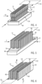
- FIG. 10 shows an alternative embodiment in which the heat-emitting element comprises several hollow cylinders 60 .
- These hollow cylinders are formed by bending the panel element and form a cavity 62 which extends at right angles to the layers of the layer structure 34 . Accordingly, the hollow cylinders 60 stand on the associated sheet metal strip.
- FIG. 10 shows rectangular hollow cylinders 60 . It goes without saying that the illustrated basic form is only exemplary.
- the hollow cylinders 60 can have any base surface, thus also be oval, round or polygonally bent.
- Several hollow cylinders 60 are provided next to each other in one plane of the layer structure at right angles to the direction of penetration F of the fluid to be heated.
- FIG. 11 shows a modification to the embodiment according to FIG. 5 .
- FIG. 11 illustrates only one single rib 70 with two main side surfaces 44 , which are connected by only one web 46 .
- Several heating ribs can of course be provided one behind the other in the direction of penetration F of the fluid to be heated as shown in FIG. 5 .
- Fastening segments 72 are formed by bending across the main direction of extension of the rib 70 . These fastening segments 72 are directly connected to the main side surface 74 of the PTC element 30 .
- energization takes place directly through the heat-emitting element 12 .
- this element may have a connecting lug formed by punching the panel element for the introduction of the power current.
- the connecting lug can also be punched out of a sheet metal material and connected to the wire mesh by soldering.
- FIG. 12 shows an example of a panel element 80 in the form of a wire mesh from which the previously discussed configuration of heat-emitting elements 12 can be bent
Landscapes
- Engineering & Computer Science (AREA)
- Physics & Mathematics (AREA)
- Thermal Sciences (AREA)
- Mechanical Engineering (AREA)
- Chemical & Material Sciences (AREA)
- Combustion & Propulsion (AREA)
- General Engineering & Computer Science (AREA)
- Direct Air Heating By Heater Or Combustion Gas (AREA)
- Air-Conditioning For Vehicles (AREA)
- Resistance Heating (AREA)
Abstract
Description
Claims (18)
Applications Claiming Priority (2)
| Application Number | Priority Date | Filing Date | Title |
|---|---|---|---|
| DE102018220858.1 | 2018-12-03 | ||
| DE102018220858.1A DE102018220858A1 (en) | 2018-12-03 | 2018-12-03 | Electric heater |
Publications (2)
| Publication Number | Publication Date |
|---|---|
| US20200171920A1 US20200171920A1 (en) | 2020-06-04 |
| US11912106B2 true US11912106B2 (en) | 2024-02-27 |
Family
ID=68762605
Family Applications (1)
| Application Number | Title | Priority Date | Filing Date |
|---|---|---|---|
| US16/701,861 Active 2041-11-10 US11912106B2 (en) | 2018-12-03 | 2019-12-03 | Electric heating device |
Country Status (4)
| Country | Link |
|---|---|
| US (1) | US11912106B2 (en) |
| EP (1) | EP3667197B1 (en) |
| CN (1) | CN111263475A (en) |
| DE (1) | DE102018220858A1 (en) |
Families Citing this family (2)
| Publication number | Priority date | Publication date | Assignee | Title |
|---|---|---|---|---|
| DE102016225462A1 (en) * | 2016-12-19 | 2018-06-21 | E.G.O. Elektro-Gerätebau GmbH | Heating device, cooking device with a heating device and method for producing a heating element |
| DE102021109618A1 (en) * | 2021-04-16 | 2022-10-20 | Eberspächer Catem Gmbh & Co. Kg | PTC heating device |
Citations (28)
| Publication number | Priority date | Publication date | Assignee | Title |
|---|---|---|---|---|
| EP0243077A2 (en) | 1986-04-17 | 1987-10-28 | Ford Motor Company Limited | An automotive type electric heater |
| US4743321A (en) | 1985-10-04 | 1988-05-10 | Raychem Corporation | Devices comprising PTC conductive polymers |
| JPH07324884A (en) | 1994-05-31 | 1995-12-12 | Showa Alum Corp | Corrugated fins for heat exchangers |
| EP1715276A2 (en) | 2005-04-18 | 2006-10-25 | Behr GmbH & Co. KG | Heat exchanger |
| DE102006018784A1 (en) * | 2005-12-20 | 2007-06-21 | Beru Ag | Heater for use in automobile, has heating device in which multiple electrical heating units are arranged, and heat exchanger formed of extruded section in which heating device is included |
| US20090026194A1 (en) * | 2007-07-18 | 2009-01-29 | Catem Gmbh & Co. Kg | Method of Manufacturing an Electric Heating Device and Electric Heating Devices |
| EP2242327A1 (en) | 2009-04-14 | 2010-10-20 | Eberspächer catem GmbH & Co. KG | Electric heating device |
| EP2299201A1 (en) | 2009-09-22 | 2011-03-23 | Eberspächer catem GmbH & Co. KG | Electric heating device |
| US20110068090A1 (en) * | 2009-09-22 | 2011-03-24 | Eberspacher Catem Gmbh & Co. Kg | Electrical heating device |
| US20110240631A1 (en) | 2007-04-04 | 2011-10-06 | Michael Luppold | Electrical heating unit, particularly for cars |
| US20120152931A1 (en) * | 2010-12-20 | 2012-06-21 | Eberspacher Catem Gmbh & Co. Kg | Electrical heating device |
| EP2607121A1 (en) | 2011-12-22 | 2013-06-26 | Eberspächer catem GmbH & Co. KG | Electric heating device, in particular for a motor vehicle |
| US20130306622A1 (en) * | 2012-05-16 | 2013-11-21 | Halla Climate Control Corp. | Heater for vehicles |
| US20140008450A1 (en) * | 2012-07-09 | 2014-01-09 | Halla Visteon Climate Control Corp. | Heater for vehicles |
| WO2014009013A2 (en) | 2012-07-11 | 2014-01-16 | Eberspächer Catem Gmbh & Co. Kg | Heat generating element |
| US20140124494A1 (en) * | 2012-11-05 | 2014-05-08 | Betacera Inc. | Car interior compartment heater |
| US20140178054A1 (en) * | 2012-12-21 | 2014-06-26 | Borgwarner Beru Systems Gmbh | Vehicle heater and method for producing a vehicle heater |
| US20150043898A1 (en) * | 2012-02-28 | 2015-02-12 | Halla Visteon Climate Control Corp. | Vehicle heater |
| DE102014208955A1 (en) | 2014-05-12 | 2015-11-12 | Fraunhofer-Gesellschaft zur Förderung der angewandten Forschung e.V. | Heat transfer device and its use |
| US20150343883A1 (en) * | 2013-01-29 | 2015-12-03 | Halla Visteon Climate Control Corp. | Heater for motor vehicle |
| WO2018105994A1 (en) * | 2016-12-05 | 2018-06-14 | 주식회사 코쿤디자인 | Display device using functional led assembly |
| US20190111763A1 (en) * | 2016-03-30 | 2019-04-18 | AMOSENSE Co.,Ltd | Ptc unit for vehicle heater, ptc heater including the same, and air conditioning device for vehicle |
| DE102017223782A1 (en) * | 2017-12-22 | 2019-06-27 | Eberspächer Catem Gmbh & Co. Kg | Heat generating element of an electric heater |
| US20190381862A1 (en) * | 2016-12-20 | 2019-12-19 | Lg Innotek Co., Ltd. | Heating rod, heating module including same, and heating device including same |
| US20200309409A1 (en) * | 2017-12-19 | 2020-10-01 | Valeo Systemes Thermiques | Electrical heating device comprising earthing means |
| US20200307355A1 (en) * | 2017-12-19 | 2020-10-01 | Valeo Systemes Thermiques | Electric heating device with grounding means |
| US20200338961A1 (en) * | 2017-08-31 | 2020-10-29 | Hanon Systems | Ptc heater |
| US20200404748A1 (en) * | 2019-06-19 | 2020-12-24 | Eberspächer Catem Gmbh & Co. Kg | Heat-Generating Element And Method For Its Production |
Family Cites Families (8)
| Publication number | Priority date | Publication date | Assignee | Title |
|---|---|---|---|---|
| EP1432287B1 (en) * | 2002-12-19 | 2006-06-21 | Catem GmbH & Co.KG | Electrical heating device with housing |
| DE50305966D1 (en) * | 2003-09-11 | 2007-01-25 | Catem Gmbh & Co Kg | Electric heater with sealed heating element |
| JP2008041298A (en) * | 2006-08-02 | 2008-02-21 | Matsushita Electric Ind Co Ltd | Flexible PTC heating element |
| ES2382138T3 (en) * | 2007-07-18 | 2012-06-05 | Eberspächer Catem Gmbh & Co. Kg | Electric heating device |
| DE102011017376A1 (en) * | 2011-04-16 | 2012-10-18 | Borgwarner Beru Systems Gmbh | Electric heater |
| CN203327269U (en) * | 2013-04-28 | 2013-12-04 | 比亚迪股份有限公司 | Electric heater, defroster, air-conditioning heating system and automobile |
| EP3101999B1 (en) * | 2015-06-02 | 2021-03-17 | Eberspächer catem GmbH & Co. KG | Ptc heating element and electric heater for a motor vehicle comprising such a ptc heating element |
| KR101913121B1 (en) * | 2016-01-28 | 2018-10-31 | 자화전자(주) | Ptc heater and apparatus for heater using the same |
-
2018
- 2018-12-03 DE DE102018220858.1A patent/DE102018220858A1/en active Pending
-
2019
- 2019-12-02 EP EP19212872.6A patent/EP3667197B1/en active Active
- 2019-12-03 US US16/701,861 patent/US11912106B2/en active Active
- 2019-12-03 CN CN201911226117.0A patent/CN111263475A/en active Pending
Patent Citations (29)
| Publication number | Priority date | Publication date | Assignee | Title |
|---|---|---|---|---|
| US4743321A (en) | 1985-10-04 | 1988-05-10 | Raychem Corporation | Devices comprising PTC conductive polymers |
| EP0243077A2 (en) | 1986-04-17 | 1987-10-28 | Ford Motor Company Limited | An automotive type electric heater |
| JPH07324884A (en) | 1994-05-31 | 1995-12-12 | Showa Alum Corp | Corrugated fins for heat exchangers |
| EP1715276A2 (en) | 2005-04-18 | 2006-10-25 | Behr GmbH & Co. KG | Heat exchanger |
| DE102006018784A1 (en) * | 2005-12-20 | 2007-06-21 | Beru Ag | Heater for use in automobile, has heating device in which multiple electrical heating units are arranged, and heat exchanger formed of extruded section in which heating device is included |
| US20110240631A1 (en) | 2007-04-04 | 2011-10-06 | Michael Luppold | Electrical heating unit, particularly for cars |
| EP2025541A1 (en) | 2007-07-18 | 2009-02-18 | Catem GmbH & Co. KG | Heating element of an electric heating device |
| US20090026194A1 (en) * | 2007-07-18 | 2009-01-29 | Catem Gmbh & Co. Kg | Method of Manufacturing an Electric Heating Device and Electric Heating Devices |
| EP2242327A1 (en) | 2009-04-14 | 2010-10-20 | Eberspächer catem GmbH & Co. KG | Electric heating device |
| EP2299201A1 (en) | 2009-09-22 | 2011-03-23 | Eberspächer catem GmbH & Co. KG | Electric heating device |
| US20110068090A1 (en) * | 2009-09-22 | 2011-03-24 | Eberspacher Catem Gmbh & Co. Kg | Electrical heating device |
| US20120152931A1 (en) * | 2010-12-20 | 2012-06-21 | Eberspacher Catem Gmbh & Co. Kg | Electrical heating device |
| EP2607121A1 (en) | 2011-12-22 | 2013-06-26 | Eberspächer catem GmbH & Co. KG | Electric heating device, in particular for a motor vehicle |
| US20150043898A1 (en) * | 2012-02-28 | 2015-02-12 | Halla Visteon Climate Control Corp. | Vehicle heater |
| US20130306622A1 (en) * | 2012-05-16 | 2013-11-21 | Halla Climate Control Corp. | Heater for vehicles |
| US20140008450A1 (en) * | 2012-07-09 | 2014-01-09 | Halla Visteon Climate Control Corp. | Heater for vehicles |
| WO2014009013A2 (en) | 2012-07-11 | 2014-01-16 | Eberspächer Catem Gmbh & Co. Kg | Heat generating element |
| US20140124494A1 (en) * | 2012-11-05 | 2014-05-08 | Betacera Inc. | Car interior compartment heater |
| US20140178054A1 (en) * | 2012-12-21 | 2014-06-26 | Borgwarner Beru Systems Gmbh | Vehicle heater and method for producing a vehicle heater |
| US20150343883A1 (en) * | 2013-01-29 | 2015-12-03 | Halla Visteon Climate Control Corp. | Heater for motor vehicle |
| DE102014208955A1 (en) | 2014-05-12 | 2015-11-12 | Fraunhofer-Gesellschaft zur Förderung der angewandten Forschung e.V. | Heat transfer device and its use |
| US20190111763A1 (en) * | 2016-03-30 | 2019-04-18 | AMOSENSE Co.,Ltd | Ptc unit for vehicle heater, ptc heater including the same, and air conditioning device for vehicle |
| WO2018105994A1 (en) * | 2016-12-05 | 2018-06-14 | 주식회사 코쿤디자인 | Display device using functional led assembly |
| US20190381862A1 (en) * | 2016-12-20 | 2019-12-19 | Lg Innotek Co., Ltd. | Heating rod, heating module including same, and heating device including same |
| US20200338961A1 (en) * | 2017-08-31 | 2020-10-29 | Hanon Systems | Ptc heater |
| US20200309409A1 (en) * | 2017-12-19 | 2020-10-01 | Valeo Systemes Thermiques | Electrical heating device comprising earthing means |
| US20200307355A1 (en) * | 2017-12-19 | 2020-10-01 | Valeo Systemes Thermiques | Electric heating device with grounding means |
| DE102017223782A1 (en) * | 2017-12-22 | 2019-06-27 | Eberspächer Catem Gmbh & Co. Kg | Heat generating element of an electric heater |
| US20200404748A1 (en) * | 2019-06-19 | 2020-12-24 | Eberspächer Catem Gmbh & Co. Kg | Heat-Generating Element And Method For Its Production |
Also Published As
| Publication number | Publication date |
|---|---|
| EP3667197B1 (en) | 2025-03-26 |
| CN111263475A (en) | 2020-06-09 |
| EP3667197A1 (en) | 2020-06-17 |
| US20200171920A1 (en) | 2020-06-04 |
| DE102018220858A1 (en) | 2020-06-04 |
Similar Documents
| Publication | Publication Date | Title |
|---|---|---|
| US7860381B2 (en) | Heating device for diesel fuel and heatable diesel filter system | |
| US11912106B2 (en) | Electric heating device | |
| US20110240631A1 (en) | Electrical heating unit, particularly for cars | |
| JP2003260925A (en) | Electric heating devices used in automobiles | |
| CN111566414B (en) | Electric heating device comprising a grounding device | |
| KR102030200B1 (en) | Insulated heating module for a supplemental heating device | |
| US7098429B2 (en) | Heat exchanger, particularly for a heating or air conditioning unit in a motor vehicle | |
| KR100759533B1 (en) | Cover-mounted car preheater | |
| US9827828B2 (en) | Vehicle heating system | |
| EP2881680B1 (en) | Electric heater | |
| CN104823004B (en) | It is heat sink, associated for thermal modules and corresponding assemble method | |
| US1731472A (en) | Radiator | |
| US4075459A (en) | Voltage tapping in electrical heating elements | |
| JPH07302656A (en) | Plug-in connector device between rear panel printed wiring board and circuit unit printed wiring board | |
| US20040200830A1 (en) | Heating device | |
| JP2007511412A (en) | A heat exchanger, in particular for an automotive heating or air conditioning device, and a method for producing this heat exchanger | |
| JP2015109274A (en) | Electric heater | |
| US11076452B2 (en) | Heating module | |
| CN101765251A (en) | Electric heating apparatus | |
| JP4106396B2 (en) | Floor heating system | |
| KR102852819B1 (en) | Rear cover assembly of vehicle air heating device and vehicle air heating device including the same | |
| US6891107B2 (en) | Device for electric contact for textile material and use thereof for joule heating | |
| KR20200089792A (en) | High Voltage PTC Heater | |
| KR20090022080A (en) | Air heater for internal combustion engine | |
| US5935469A (en) | Insulating staple for holding the resistive member of a heating element in place |
Legal Events
| Date | Code | Title | Description |
|---|---|---|---|
| FEPP | Fee payment procedure |
Free format text: ENTITY STATUS SET TO UNDISCOUNTED (ORIGINAL EVENT CODE: BIG.); ENTITY STATUS OF PATENT OWNER: LARGE ENTITY |
|
| STPP | Information on status: patent application and granting procedure in general |
Free format text: DOCKETED NEW CASE - READY FOR EXAMINATION |
|
| STPP | Information on status: patent application and granting procedure in general |
Free format text: NON FINAL ACTION MAILED |
|
| STPP | Information on status: patent application and granting procedure in general |
Free format text: RESPONSE TO NON-FINAL OFFICE ACTION ENTERED AND FORWARDED TO EXAMINER |
|
| STPP | Information on status: patent application and granting procedure in general |
Free format text: FINAL REJECTION MAILED |
|
| STPP | Information on status: patent application and granting procedure in general |
Free format text: RESPONSE AFTER FINAL ACTION FORWARDED TO EXAMINER |
|
| STPP | Information on status: patent application and granting procedure in general |
Free format text: NOTICE OF ALLOWANCE MAILED -- APPLICATION RECEIVED IN OFFICE OF PUBLICATIONS |
|
| STPP | Information on status: patent application and granting procedure in general |
Free format text: AWAITING TC RESP., ISSUE FEE NOT PAID |
|
| STPP | Information on status: patent application and granting procedure in general |
Free format text: RESPONSE TO NON-FINAL OFFICE ACTION ENTERED AND FORWARDED TO EXAMINER |
|
| STPP | Information on status: patent application and granting procedure in general |
Free format text: NOTICE OF ALLOWANCE MAILED -- APPLICATION RECEIVED IN OFFICE OF PUBLICATIONS |
|
| STPP | Information on status: patent application and granting procedure in general |
Free format text: PUBLICATIONS -- ISSUE FEE PAYMENT VERIFIED |
|
| STCF | Information on status: patent grant |
Free format text: PATENTED CASE |