TECHNICAL FIELD
The present disclosure relates generally to the field of rotary-wing aircraft actuation systems, and more particularly to a rotary-wing aircraft rotor blade pitch control system.
BACKGROUND ART
Rotary-wing aircraft, such as helicopters, are typically propelled by a main rotor having a hub rotatably supported on a rotor mast and supporting a plurality of rotor blades extending radially outward from the hub. To control vertical lift or altitude, the pitch of the rotating blades is typically adjusted collectively through a rotating swash plate that is coupled to the blades by respective linkages. This adjustment of the pitch of the blades changes a blade's angle of attack relative to the stream of air moving past it. The higher the angle of attack, the more highly loaded the blade becomes in creating more lift.
To control horizontal movement, the pitch of each blade is varied by a given amount once per rotor revolution. Conventionally, this tilting of the rotor is affected by tilting the swash plate, which results in the pitch of each of the blades changing twice per revolution of the hub. For example, to move the aircraft directly forward, the pitch of each blade is increased each time that blade passes over the tail of the aircraft, such that the lift developed by that blade is then temporarily greater than that of the other blades, and thereby results in a forward thrust component being applied to the aircraft by the rotor.
The pitch of each blade in a conventional rotor is controlled by a control rod, and the positions of all such rods are typically controlled by a single swashplate. The control rods are mounted circumferentially around the swashplate so that axial movement of the swashplate causes collective changes in pitch. Longitudinal and lateral tilting of the swashplate results in cyclic pitch control.
Individual blade control systems have been used to enable the pitch of each blade to be varied independently of the others. Typical approaches to individual blade control utilize either electrical motor actuators and slip rings, or hydraulic actuators, hydraulic swivels and electrical slip ring systems.
U.S. Pat. No. 4,519,743, entitled “Helicopter Individual Blade Control System,” is directed to a system in which the pitch of the blades of a helicopter rotor assembly are controlled by individual blade control subsystems that respond to output signals from accelerometers mounted on the blades.
U.S. Pat. No. 4,930,988, entitled “Individual Blade Control System for Helicopters,” is directed to a control system for providing individual blade control inputs to a four-bladed helicopter rotor. Motion is transmitted to the rotor blades through a conventional swashplate which drives four blades of the rotor and a translatable differential sleeve and summing linkage which drives only two blades.
U.S. Pat. No. 7,674,091, entitled “Rotor Blade Pitch Control,” is directed to a mechanical independent blade control mechanism for controlling the pitch of each of the blades of a rotor blade system independently of the other blades. The system includes a plurality of actuators disposed in the fuselage below the hub of the rotor, each being operable to selectively control the pitch of an associated one of the blades independently of the other blades, and a plurality of mechanical linkages disposed within the annulus of the rotor mast, each coupled between a blade and an actuator and operable to transmit a force output by the actuator to a pitch horn fixed to an inner end of the associated blade.
BRIEF SUMMARY
With parenthetical reference to the corresponding parts, portions or surfaces of the disclosed embodiment, merely for purposes of illustration and not by way of limitation, an rotor blade pitch control system (15) for a rotary-wing aircraft (16) having a plurality of rotor blades mounted to a main rotor and driven about a central axis of rotation at an operational speed and in a rotational direction relative to a non-rotating body of the aircraft is provided comprising: a first rotor blade (19 a) connected to a main rotor (17) and operatively configured to be driven about a central axis of rotation (20) relative to a non-rotating body (21) of the aircraft; the first rotor blade (19 a) rotatable about a first pitch axis (24 a); a first blade pitch control motor (30 a) having a first stator (31 a), a first pitch drive rotor (32 a) and a first pitch follower (40 a); a first linkage (50 a) extending between the first pitch follower (40 a) and the first rotor blade (19 a); a first rotor blade coupling (58 a) between the first linkage (50 a) and the first rotor blade (19 a); the first rotor blade coupling (58 a) having a first rotor blade coupling center (59 a); a first pitch follower coupling (51 a) between the first linkage (50 a) and the first pitch follower (40 a); the first pitch follower coupling (51 a) having a first pitch follower coupling center (52 a); a first hinge coupling (53 a) between the first linkage (50 a) and the main rotor (17); the first hinge coupling (53 a) having a first hinge axis (54 a); the first pitch drive rotor (32 a) having a first cam surface (36 a) orientated about a first driven axis (35 a) that is eccentric to the central axis of rotation (20); the first linkage (50 a) extending between the main rotor (17) and the first pitch follower (40 a) such that the first pitch follower coupling center (52 a) rotates about the central axis of rotation (20) with rotation of the first hinge coupling (53 a) about the central axis of rotation (20); the first pitch drive rotor (32 a) operatively configured to be driven about the central axis of rotation (20) independently of the main rotor (17) to selectively rotate the first driven axis (35 a) about the central axis of rotation (20); the first driven axis (35 a) and the first pitch follower coupling center (52 a) having a selectively variable first displacement angle (80 a) defined by an inclusive angle between a line (81 a) extending radially between the central axis of rotation (20) and the first driven axis (35 a) and a line (82 a) extending radially between the central axis of rotation (20) and the first pitch follower coupling center (52 a); wherein the first pitch drive rotor (32 a) may be rotated about the central axis of rotation (20) relative to the main rotor (17) to control a pitch (71 a) of the first rotor blade (19 a) about the first pitch axis (24 a).
The first displacement angle (80 a) may range from a minimum displacement angle (0°) to a maximum displacement angle (180°), the pitch may range from a first pitch angle limit (74 a) to a second pitch angle limit (75 a), and when the first displacement angle is the maximum (180°), the pitch may be the first pitch angle limit (74 a), and when the first displacement angle is the minimum (00), the pitch may be the second pitch angle limit (75 a). The pitch may comprise a neutral pitch angle (76 a), and when the first displacement angle is about half of the maximum (90°), the pitch may be the neutral pitch angle (76 a).
The first linkage may comprise a first transfer link (60 a) and a first pitch link (64 a); the main rotor (17) may comprise a hinge hub (25); and the first rotor blade (19 a) may comprise a pitch horn (65 a). The first transfer link (60 a) may be coupled to the first pitch follower (40 a) by the first pitch follower coupling (51 a); the first transfer link (60 a) may be coupled to the hinge hub (25) of the main rotor (17) by the first hinge coupling (53 a); the first pitch link (60 a) may be coupled to the first pitch horn (65 a) of the first rotor blade (19 a) by the first rotor blade coupling (58 a); and the first transfer link (60 a) may be coupled to the first pitch link (64 a) by a first intermediate coupling (55 a) having a first intermediate coupling center (56 a). The first rotor blade coupling center (59 a) of the first rotor blade coupling (58 a) may be offset a pitch horn distance (66 a) from the first pitch axis (24 a). The first pitch follower coupling may comprise a ball joint or a universal coupling.
The first pitch follower (40 a) may be rotatable relative to the first pitch drive rotor (32 a) about the first driven axis (35 a). The first pitch drive rotor (32 a) may comprise a first annular drive bore (34 a) having a first drive axis coincident with the central axis of rotation (20); the first cam surface of the first pitch drive rotor (32 a) may comprise a first outer annular rim (36 a) having a first rim axis coincident with the first driven axis (35 a); and the first pitch follower (40 a) may comprise a first annular following bore (42 a) having a first following bore axis coincident with the first rim axis (35 a). The rotor blade pitch control system may comprise an annular bearing (43 a) between the first outer annular rim (36 a) and the first annular following bore (42 a). The first pitch drive rotor (32 a) may radially constrain the first pitch follower (40 a) relative to the central axis of rotation (20).
The rotor blade pitch control system may comprise a controller (90) that receives input signals and outputs command signals to the first blade pitch control motor (30 a) to control a speed of rotation of the first pitch drive rotor (32 a) about the central axis of rotation (20) and the first displacement angle (80 a). The controller may vary the first displacement angle (80 a) to vary the pitch (71 a) of the first rotor blade (19 a) about the first pitch axis (24 a). The first displacement angle (80 a) may be variable from 0 degrees to 180 degrees. The controller (90) may maintain a constant first displacement angle (80 a) to maintain a desired constant pitch (71 a) of the first rotor blade (19 a) about the first pitch axis (24 a). The controller may selectively control the first blade pitch control motor (30 a) such that the first driven axis (35 a) rotates about the central axis of rotation (20) at a first rotational speed and the main rotor (17) rotates about the central axis of rotation at a second rotational speed, whereby the controller (90) controls a speed differential between the first speed of rotation of the first driven axis (35 a) about the central axis of rotation (20) and the second speed of rotation of the main rotor (17) about the central axis of rotation (20). The controller may vary the first displacement angle (80 a) by varying the speed differential from substantially 1 to 1. The controller (90) may vary the pitch (71 a) of the first rotor blade (19 a) about the first pitch axis (24 a) by varying the speed differential such that the first rotational speed that the first driven axis (35 a) rotates about the central axis of rotation (20) is different from the second rotational speed that the main rotor (17) rotates about the central axis of rotation (20).
The rotor blade pitch control system may comprise a unit frame (29) mounted to a non-rotating body (26) of the aircraft; the first stator (31 a) of the first blade pitch control motor (30 a) may be mounted to the unit frame (29); and the first pitch drive rotor (32 a) may have an annular stator-facing portion (34 a) and a plurality of magnets (39 a) supported by the annular stator-facing portion (34 a).
The rotor blade pitch control system may comprise: a second rotor blade (19 b) connected to the main rotor (17) and operatively configured to be driven about the central axis of rotation (20) relative to the non-rotating body (21) of the aircraft; the second rotor blade (19 b) rotatable about a second pitch axis (24 b); a second blade pitch control motor (30 b) having a second stator (31 b), a second pitch drive rotor (32 b) and a second pitch follower (40 b); a second linkage (50 b) extending between the second pitch follower (40 b) and the second rotor blade (19 b); a second rotor blade coupling (58 b) between the second linkage (50 b) and the second rotor blade (19 b); the second rotor blade coupling (58 b) having a second rotor blade coupling center (59 b); a second pitch follower coupling (51 b) between the second linkage (50 b) and the second pitch follower (40 b); the second pitch follower coupling (51 b) having a second pitch follower coupling center (52 b); a second hinge coupling (53 b) between the second linkage (50 b) and the main rotor (17); the second hinge coupling (53 b) having a second hinge axis (54 b); the second pitch drive rotor (32 b) having a second cam surface (36 b) orientated about a second driven axis (35 b) that is eccentric to the central axis of rotation (20); the second linkage (50 b) extending between the main rotor (17) and the second pitch follower (40 b) such that the second pitch follower coupling center (52 b) rotates about the central axis of rotation (20) with rotation of the second hinge coupling (53 b) about the central axis of rotation (20); the second pitch drive rotor (32 b) operatively configured to be driven about the central axis of rotation (20) independently of the main rotor (17) and independently of the first pitch drive rotor (32 a) to selectively rotate the second driven axis (35 b) about the central axis of rotation (20); and the second driven axis (35 b) and the second pitch follower coupling center (52 b) having a selectively variable second displacement angle (80 b) defined by an inclusive angle between a line (81 b) extending radially between the central axis of rotation (20) and the second driven axis (35 b) and a line (82 b) extending radially between the central axis of rotation (20) and the second pitch follower coupling center (52 b); wherein the second pitch drive rotor (32 b) may be rotated about the central axis of rotation (20) relative to the main rotor (17) to control a pitch (71 b) of the second rotor blade (19 b) about the second pitch axis (24 b) independently of the control of the pitch of the first rotor blade (19 a) about the first pitch axis (24 a). The rotor blade pitch control system may comprise a controller (90) that receives input signals and outputs command signals to the second blade pitch control motor (30 b) to control a speed of rotation of the second pitch drive rotor (32 b) about the central axis of rotation (20) and the second displacement angle (80 b).
In another aspect, a rotor blade pitch control system is provided comprising: a first rotor blade (19 a) operatively configured to be driven about a central axis of rotation (20); the first rotor blade (19 a) rotatable about a first pitch axis (24 a); a first pitch drive rotor (32 a) operatively configured to be driven about the central axis of rotation (20) independently of rotation of the first rotor blade (19 a) about the central axis of rotation (20); a first pitch follower (40 a) rotatable relative to the first pitch drive rotor (32 a); the first pitch follower (40 a) and the first rotor blade (19 a) coupled (50 a) such that the first pitch follower (40 a) rotates with rotation of the first rotor blade (19 a) about the central axis of rotation (20); the first pitch drive rotor (32 a), the first pitch follower (40 a) and the first rotor blade (19 a) coupled (50 a) such that the first pitch drive rotor (32 a) is operatively configured to be driven to control an angular displacement (80 a) of the first pitch drive rotor (32 a) relative to the first pitch follower (40 a) about the central axis of rotation (20) and thereby control a pitch (71 a) of the first rotor blade (19 a) about the first pitch axis (24 a).
The rotor blade pitch control system may comprise: a second rotor blade (19 b) operatively configured to be driven about the central axis of rotation (20); the second rotor blade (19 b) rotatable about a second pitch axis (24 b); a second pitch drive rotor (32 b) operatively configured to be driven about the central axis of rotation (20) independently of rotation of the second rotor blade (19 b) about the central axis of rotation (20) and independently of the first pitch drive rotor (32 a) about the central axis of rotation (20); a second pitch follower (40 b) rotatable relative to the second pitch drive rotor (32 b); the second pitch follower (40 b) and the second rotor blade (19 b) coupled (50 b) such that the second pitch follower (40 b) rotates with rotation of the second rotor blade (19 b) about the central axis of rotation (20); the second pitch drive rotor (32 b), the second pitch follower (40 b) and the second rotor blade (19 b) coupled (50 b) such that the second pitch drive rotor (32 b) is operatively configured to be driven to control an angular displacement (80 b) of the second pitch drive rotor (32 b) relative to the second pitch follower (40 b) about the central axis of rotation (20) and thereby control a pitch (71 b) of the second rotor blade (19 b) about the second pitch axis (24 b) independently of the control of the pitch (71 a) of the first rotor blade (19 a) about the first pitch axis (24 a).
The rotor blade pitch control system may comprise a first linkage (50 a) between the first pitch follower (40 a) and the first rotor blade (19 a). The rotor blade pitch control system may comprise: a first pitch follower coupling (51 a) between the first linkage (50 a) and the first pitch follower (40 a); the first pitch follower coupling (51 a) having a first pitch follower coupling center (52 a); the first pitch drive rotor (32 a) having a first cam surface (36 a) orientated about a first driven axis (35 a) that is eccentric to the central axis of rotation (20); and wherein the angular displacement (80 a) of the first pitch drive rotor (32 a) relative to the first pitch follower (40 a) comprises a selectively variable first displacement angle defined by an inclusive angle between a line (81 a) extending radially between the central axis of rotation (20) and the first driven axis (35 a) and a line (82 a) extending radially between the central axis of rotation (20) and the first pitch follower coupling center (52 a). The rotor blade pitch control system may comprise: a main rotor (17) connected to the first rotor blade (19 a) and operatively configured to be driven about the central axis of rotation (20); a first hinge coupling (53 a) between the first linkage (50 a) and the main rotor (17); the first hinge coupling (53 a) having a first hinge axis (54 a); and the first linkage (50 a) extending between the main rotor (17) and the first pitch follower (40 a) such that the first pitch follower coupling center (52 a) rotates about the central axis of rotation (20) with rotation of the first hinge coupling (53 a) about the central axis of rotation (20).
The rotor blade pitch control system may comprise a first blade pitch control motor (30 a) operatively configured to drive the first pitch drive rotor (32 a) about the central axis of rotation (20) and a controller (90) that receives input signals and outputs command signals to the first blade pitch control motor (30 a) to control a speed of rotation of the first pitch drive rotor (32 a) about the central axis of rotation (20) and the angular displacement (80 a) of the first pitch drive rotor (32 a) relative to the first pitch follower (40 a) about the central axis of rotation (20).
BRIEF DESCRIPTION OF THE DRAWINGS
FIG. 1 is a representative perspective view of a first embodiment of the improved individual rotor blade pitch control system on a main rotor assembly of a helicopter.
FIG. 2 is an enlarged representative perspective view of the individual rotor blade pitch control system shown in FIG. 1 .
FIG. 3 is a vertical cross-sectional view of the individual rotor blade pitch control system shown in FIG. 1 .
FIG. 4 is a partial vertical cross-sectional representative view of a pitch rotor and pitch follower assembly of the individual blade pitch control system shown in FIG. 1 .
FIG. 5 is a top plan diagram view of the assembly shown in FIG. 4 .
FIG. 5A is a top plan diagram view of the assembly shown in FIG. 5 in an upper pitch angle limit configuration.
FIG. 5B is a top plan diagram view of the assembly shown in FIG. 5 in lower pitch angle limit configuration.
FIG. 5C is a top plan diagram view of the assembly shown in FIG. 5 in an intermediate pitch angle limit configuration.
FIG. 6A is a representative perspective view of a pitch control subsystem for the first of the rotor blades shown in FIG. 1 in an upper pitch angle limit configuration.
FIG. 6B is a representative perspective view of a pitch control subsystem for the first of the rotor blades shown in FIG. 1 in a lower pitch angle limit configuration.
FIG. 6C is a representative perspective view of a pitch control subsystem for the first of the rotor blades shown in FIG. 1 in an intermediate pitch angle limit configuration.
FIG. 7A is a representative perspective view of a pitch control subsystem for the second of the rotor blades shown in FIG. 1 in an upper pitch angle limit configuration.
FIG. 7B is a representative perspective view of a pitch control subsystem for the second of the rotor blades shown in FIG. 1 in a lower pitch angle limit configuration.
FIG. 7C is a representative perspective view of a pitch control subsystem for the second of the rotor blades shown in FIG. 1 in an intermediate pitch angle limit configuration.
FIG. 8A is a representative perspective view of a pitch control subsystem for the third of the rotor blades shown in FIG. 1 in an upper pitch angle limit configuration.
FIG. 8B is a representative perspective view of a pitch control subsystem for the third of the rotor blades shown in FIG. 1 in a lower pitch angle limit configuration.
FIG. 8C is a representative perspective view of a pitch control subsystem for the third of the rotor blades shown in FIG. 1 in an intermediate pitch angle limit configuration.
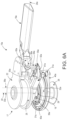
FIG. 9A is a representative perspective view of a pitch control subsystem for the fourth of the rotor blades shown in FIG. 1 in an upper pitch angle limit configuration.
FIG. 9B is a representative perspective view of a pitch control subsystem for the fourth of the rotor blades shown in FIG. 1 in a lower pitch angle limit configuration.
FIG. 9C is a representative perspective view of a pitch control subsystem for the fourth of the rotor blades shown in FIG. 1 in an intermediate pitch angle limit configuration.
FIG. 10 is a schematic diagram of the control system for the pitch control subsystems shown in FIG. 1 .
DETAILED DESCRIPTION OF THE EMBODIMENTS
At the outset, it should be clearly understood that like reference numerals are intended to identify the same structural elements, portions or surfaces consistently throughout the several drawing figures, as such elements, portions or surfaces may be further described or explained by the entire written specification, of which this detailed description is an integral part. Unless otherwise indicated, the drawings are intended to be read (e.g., crosshatching, arrangement of parts, proportion, degree, etc.) together with the specification, and are to be considered a portion of the entire written description. As used in the following description, the terms “horizontal”, “vertical”, “left”, “right”, “up” and “down”, as well as adjectival and adverbial derivatives thereof (e.g., “horizontally”, “rightwardly”, “upwardly”, etc.), simply refer to the orientation of the illustrated structure as the particular drawing figure faces the reader. Similarly, the terms “inwardly” and “outwardly” generally refer to the orientation of a surface relative to its axis of elongation, or axis of rotation, as appropriate.
FIG. 1 is a schematic illustration of helicopter 16 having airframe 21 and main rotor 17 that is driven about center axis of rotation 20. Main rotor 17 includes rotor blades 19 a, 19 b, 19 c and 19 d rotationally mounted to main rotor blade hub 22 on main rotor 17 via rotor blade grips 23 a, 23 b, 23 c and 23 d that allow the rotor blades to be rotated about their pitch axes 24 a, 24 b, 24 c and 24 d, respectively, so that the pitch of the rotor blades may be selectively varied. Rotor blades 19 a, 19 b, 19 c and 19 d have pitch horns 65 a, 65 b, 65 c and 65 d, respectively, to which a torque may be applied to control the respective pitch angle 71 a, 71 b, 71 c and 71 d of the rotor blade about its pitch axis 24 a, 24 b, 24 c and 24 d, respectively.
Rotor blade hub 22 is driven about central axis of rotation 20 by main rotor shaft 18, which is driven through a main rotor gear box by one or more aircraft engines. Main rotor shaft 18 and blade hub 22 rotate in a rotational direction and at an operational rotational frequency about center axis of rotation 20. Although a helicopter is shown and described in this embodiment, rotor blade pitch control system 15 may be used with other types or configurations of rotary-wing aircraft or rotor-craft or in other pitch control applications.
As shown in FIGS. 1-4 , rotor blade pitch control system 15 is mounted between fuselage 21 and main rotor 17 and is generally orientated concentrically with main rotor 17. FIG. 1 provides a frame of reference comprising longitudinal axis x-x aligned with the longitudinal axis of helicopter 16, transverse axis y-y perpendicular to axis x-x, and vertical axis z-z concentric with central axis of rotation 20 of main rotor 17.
As shown in FIGS. 2-4 , rotor blade pitch control system 15 generally includes first pitch control motor 30 a mounted to static mast 26 of airframe 21 of helicopter 16, first linkage 50 a connecting first pitch control motor 30 a and first rotor blade 19 a, second pitch control motor 30 b mounted to static mast 26 of airframe 21 of helicopter 16, second linkage 50 b connecting second pitch control motor 30 b and second rotor blade 19 b, third pitch control motor 30 c mounted to static mast 26 of airframe 21 of helicopter 16, third linkage 50 c connecting third pitch control motor 30 c and third rotor blade 19 c, fourth pitch control motor 30 d mounted to static mast 26 of airframe 21 of helicopter 16, and fourth linkage 50 d connecting fourth pitch control motor 30 d and fourth rotor blade 19 d.
Rotor blade pitch control system 15 includes cylindrical support frame 29 orientated coaxially with main rotor 17 about central axis 20. Support frame 29 is fixed to static mast 26 of helicopter 16 and does not rotate relative to fuselage 21 of helicopter 16. Frame 29 supports each of pitch motors 30 a, 30 b, 30 c and 30 d.
Motor 30 a comprises stator 31 a, fixed to frame 29, and rotor 32 a that is driven to rotate about drive axis 33 a relative to stator 31 a. In this embodiment, drive axis 33 a is coaxial with central axis 20. Upper and lower bearings 37 a act between rotor 32 a and frame 29 such that rotor 32 a is driven by motor 30 a to rotate about axis 33 a relative to frame 29. In this embodiment, motor 30 a is a rotary brushless permanent magnet electric motor with rotor 32 a having permanent magnets 39 a spaced around its inwardly-facing annular stator-facing surface 34 a and stator 31 a having coils energized to drive rotor 32 a about axis 33 a in either rotational direction.
Motor 30 b comprises stator 31 b, fixed to frame 29, and rotor 32 b that is driven to rotate about drive axis 33 b relative to stator 31 b. In this embodiment, drive axis 33 b is coaxial with central axis 20. Upper and lower bearings 37 b act between rotor 32 b and frame 29 such that rotor 32 b is driven by motor 30 b to rotate about axis 33 b relative to frame 29. In this embodiment, motor 30 b is a rotary brushless permanent magnet electric motor with rotor 32 b having permanent magnets 39 b spaced around its inwardly-facing annular stator-facing surface 34 b and stator 31 b having coils energized to drive rotor 32 b about axis 33 b in either rotational direction.
Motor 30 c comprises stator 31 c, fixed to frame 29, and rotor 32 c that is driven to rotate about drive axis 33 c relative to stator 31 c. In this embodiment, drive axis 33 c is coaxial with central axis 20. Upper and lower bearings 37 c act between rotor 32 c and frame 29 such that rotor 32 c is driven by motor 30 c to rotate about axis 33 c relative to frame 29. In this embodiment, motor 30 c is a rotary brushless permanent magnet electric motor with rotor 32 c having permanent magnets 39 c spaced around its inwardly-facing annular stator-facing surface 34 c and stator 31 c having coils energized to drive rotor 32 c about axis 33 c in either rotational direction.
Motor 30 d comprises stator 31 d, fixed to frame 29, and rotor 32 d that is driven to rotate about drive axis 33 d relative to stator 31 d. In this embodiment, drive axis 33 d is coaxial with central axis 20. Upper and lower bearings 37 d act between rotor 32 d and frame 29 such that rotor 32 d is driven by motor 30 d to rotate about axis 33 d relative to frame 29. In this embodiment, motor 30 d is a rotary brushless permanent magnet electric motor with rotor 32 d having permanent magnets 39 d spaced around its inwardly-facing annular stator-facing surface 34 d and stator 31 d having coils energized to drive rotor 32 d about axis 33 d in either rotational direction.
In this embodiment, motor axis 33 a, motor axis 33 b, motor axis 33 c, motor axis 33 d and central axis 20 are coaxial and rotors 32 a, 32 b, 32 c and 32 d are directly driven by motors 30 a, 30 b, 30 c and 30 d, respectively. However, alternatively such rotors could be indirectly driven through gear trains, belts or other rotational couplings, and could be non-concentric to each other and to central axis 20.
Drive rotor 32 a of first motor 30 a is rotationally coupled via follower 40 a to linkage 50 a at spherical bearing 51 a, drive rotor 32 b of second motor 30 b is rotationally coupled via follower 40 b to linkage 50 b at spherical bearing 51 b, drive rotor 32 c of third motor 30 c is rotationally coupled via follower 40 c to linkage 50 c at spherical bearing 51 c, and drive rotor 32 d of fourth motor 30 d is rotationally coupled via follower 40 d to linkage 50 d at spherical bearing 51 d.
Inner directly driven rotor 32 a is rotationally coupled to outer follower 40 a such that follower 40 a and inner rotor 32 a are rotatable relative to each other. As further described below, follower 40 a rotates via linkage 50 a with main rotor 17, which in turn is driven by the engine of helicopter 16 about central axis 20. As further described below, drive rotor 32 a has driven axis 35 a that is selectively driven to rotate about central axis 20 by motor 30 a independently of main rotor 17.
Rotor 32 a includes an inner bore defined by inner annular surface 34 a orientated about drive axis 33 a that is coincident with central axis 20, and outer annular rim 36 a orientated about driven axis 35 a. Driven axis 35 a is parallel to and not coaxial with drive axis 33 a, such that driven axis 35 a is radially offset eccentric radial distance 38 a from central axis 20 and drive axis 33 a. Follower 40 a has an inner annular bore defined by inner annular surface 42 a, which is orientated about driven axis 35 a and coaxially with outer annular rim 36 a of rotor 32 a. As shown, spherical coupling 51 a couples follower 40 a to one end of linkage 50 a at coupling center 52 a. Coupling center 52 a and follower 40 a will rotate about driven axis 35 a with rotation of main rotor 17 about central axis 20. Annular bearing 43 a acts between rotor 32 a and follower 40 a such that follower 40 a may rotate, via linkage 50 a, with rotation of main rotor 17 relative to drive rotor 32 a. As explained further below, the relative angular positions of drive rotor 32 a and follower 40 a about central axis 20 dictate the pitch of rotor blade 19 a about pitch axis 24 a.
As shown, rotor 32 a is rotationally supported by frame 29. Upper and lower bearing pairs 37 a act between the outer cylindrical bearing surfaces of frame 29 and the opposed inner cylindrical bearing surfaces 34 a of rotor 32 a. Rotor 32 a is thereby configured to rotate about axis 20 on upper and lower annular bearing pairs 37 a. Thus, rotor 32 a is mounted on frame 29 by rolling bearings 37 a such that drive rotor 32 a is rotatable relative to frame 29 and fuselage 21.
Follower 40 a is rotationally supported between rotor 32 a and linkage 50 a. Upper and lower bearing pairs 43 a act between outer cylindrical bearing surface 36 a of rotor 32 a and opposed inner cylindrical bearing surface 42 a of follower 40 a. Follower 40 a is configured to rotate about driven axis 35 a on upper and lower bearing pairs 43 a. Thus, follower 40 a is mounted on rotor 32 a by rolling bearings 43 a such that follower 40 a is rotatable about central axis 20 relative to rotor 32 a.
As shown, the outer end of follower 40 a is rotationally supported, via spherical bearing 51 a having coupling center 52 a, by the follower end of linkage 50 a. Linkage 50 a is rotationally supported, via hinge joint 53 a having hinge axis 54 a, by hinge hub 25 of main rotor 17. The pitch horn end of linkage 50 a is rotationally supported, via spherical bearing 58 a having coupling center 59 a, by pitch horn 65 a of rotor blade 19 a. In this embodiment, linkage 50 a comprises an L-shaped lever transfer link 60 a, having first arm 61 a and second arm 62 a that pivot about hinge axis 54 a, and pitch rod 64 a. Pitch rod 64 a is coupled at one end to the end of pitch horn 65 a of rotor blade 19 a by spherical joint 58 a. Pitch rod 64 a is coupled at the other end to the end of second arm 62 a by spherical joint 55 a. The end of first arm 61 a of transfer link 60 a is coupled to the outer end of follower 40 a by spherical joint 51 a. Spherical bearing 51 a couples follower 40 a to the end of first arm 61 a of transfer link 60 a at coupling center 52 a.
As shown in FIG. 3 , spherical bearing 51 a is a rotary coupling about center 52 a between first arm 61 a of linkage 50 a and follower 40 a. Follower 40 a has an inner race 95 a orientated about coupling center 52 a such that it rotates with rotation of follower 40 a. Race 95 a has a spherical inner diameter surface orientated about center 52 a. The end portion of arm 61 a, opposite to fulcrum portion 63 a, extends through and is in linear sliding engagement with a through-bore in ball 96 a. Ball 96 a has an outer spherical diameter surface orientated about center 52 a and is retained in race 95 a of follower 40 a, with the outer surface of ball 96 a in spherical sliding engagement with the inner surface of race 95 a. Thus, race 95 a rotates with rotation of follower 40 a, and ball 96 a is rotatable with arm 61 a in at least two degrees of motion about coupling center 52 a relative to follower 40 a. The shaft end portion of arm 61 a may slide in the through-bore of ball 96 a and is in linear sliding engagement with ball 96 a such that arm 61 a may translate linearly through coupling center 52 a relative to ball 96 a. Spherical bearings 51 b, 51 c and 51 d are configured between linkages 50 b, 50 c, and 50 d and followers 40 b, 40 c, 40 d, respectively, in substantially the same manner.
Spherical bearing 55 a is a rotary coupling about center 56 a between arm 62 a of transfer link 60 a and pitch rod 64 a. The end portion of pitch rod 64 a has a race with a spherical inner diameter surface orientated about coupling center 56 a. Arm 62 a has a clevis pin rotationally supporting a ball with an outer spherical diameter surface orientated about coupling center 56 a. The ball of arm 62 a is retained in the race of pitch rod 64 a, with the outer surface of the ball in spherical sliding engagement with the inner surface of the race. Thus, the race of pitch rod 64 a and the ball of arm 62 a may rotate in at least two degrees of motion about coupling center 56 a relative to each other. Spherical bearings 55 b, 55 c and 55 d are configured between links 60 b, 60 c and 60 d and rods 64 b, 64 c and 64 d, respectively, in substantially the same manner.
Similarly, spherical bearing 58 a is a rotary coupling about center 59 a between pitch horn 65 a of rotor blade 19 a and pitch rod 64 a. The end portion of pitch rod 64 a has a race with a spherical inner diameter surface orientated about coupling center 59 a. Pitch horn 65 a has a clevis pin rotationally supporting a ball with an outer spherical diameter surface orientated about coupling center 59 a. The ball of pitch horn 65 a is retained in the race of pitch rod 64 a, with the outer surface of the ball in spherical sliding engagement with the inner surface of the race. Thus, the race of pitch rod 64 a and the ball of pitch horn 65 a may rotate in at least two degrees of motion about coupling center 59 a relative to each other. Spherical bearings 58 b, 58 c and 58 d are configured between pitch horns 65 b, 65 c and 65 d and rods 64 b, 64 c and 64 d, respectively, in substantially the same manner.
While in the above embodiment couplings 51 a, 51 b, 51 c, 51 d, 55 a, 55 b, 55 c, 55 d, 58 a, 58 b, 58 c and 58 d comprise spherical bearings, it is contemplated that other various alternative rotational couplings or pivot joints may be employed. For example, and without limitation, gimbal or universal joint type couplings may be used as alternatives.
Blade hub 22 and hinge hub 25 are fixed to rotor shaft 18 of rotor 17. Blade hub 22 with rotor blade 19 a, and hinge hub 25 with hinge joint 53 a, are stacked axially relative to central axis 20. Coupling center 59 a of pitch rod 64 a is offset fixed pitch horn distance 66 a from pitch axis 24 a. Coupling center 59 a of pitch rod 64 a is offset axially from hinge axis 54 a by a variable axial pitch link distance 70 a that varies as a function of radial distance 83 a between coupling center 52 a and central axis of rotation 20. Motor 30 a and follower 40 a with coupling 51 a are stacked axially below hinge hub 25 relative to central axis 20.
As show, transfer link 60 a pivots about hinge axis 54 a. Hinge axis 54 a is positioned tangent to a circle having radius 68 about central axis 20 such that transfer link 60 a pivots in a vertical plane B that is radial to central axis 20. With lever arms 61 a and 62 a, elbow 63 a at hinge 53 a acts as a fulcrum. Radial movement of coupling center 52 a towards central axis 20 causes coupling center 56 a to rotate about hinge axis 54 a down and away from blade hub 22, which, via pitch rod 64 a and pitch horn 65 a, rotates blade 19 a in a first direction 73 about pitch axis 24 a. Radial movement of coupling center 52 a away from central axis 20 causes coupling center 56 a to rotate about hinge axis 54 a up and towards blade hub 22, which, via pitch rod 64 a and pitch horn 65 a, rotates blade 19 a in a second direction 72 about pitch axis 24 a.
Based on the angular displacement between main rotor 17 and drive rotor 32 a, coupling center 52 a has a selectively variable radial displacement distance 83 a (r) from central axis 20 ranging from a minimum distance (r min), as shown in FIG. 5B, to a maximum distance (r max), as shown in FIG. 5A. With the configuration of linkage 50 a, based on the radial displacement distance 83 a (r) of coupling center 52 a from central axis 20, coupling center 59 a will have a selectively variable pitch angle 71 a (∠p) about pitch axis 24 a between upper angular pitch angle limit 74 a and lower angular pitch angle limit 75 a. As shown, the pitch angle 71 a (∠p), between upper limit pitch angle 74 a and lower limit pitch angle 75 a, is selectively varied by selectively varying radial displacement distance 83 a (r) from central axis 20 from a minimum distance (r min) to a maximum distance (r max). In this embodiment, the maximum radial displacement distance 83 a from central axis 20 (r max) corresponds to rotor blade 19 a having first angular pitch angle limit 74 a, and the minimum radial displacement distance 83 a from central axis 20 (r min) corresponds to rotor blade 19 a having second angular pitch angle limit 75 a. Thus, system 15 provides rotor blade 19 a with a pitch angle rotational range 71 a between upper limit 74 a and lower limit 75 a that is based on and a direct function of the radial linear displacement range 84 a of coupling center 52 a from central axis 20. Based on the radial displacement distance 83 a (r) of coupling center 52 a from central axis 20, blade 19 a has a selectively variable pitch about pitch axis 24 a.
With the configuration of linkage 50 a in this embodiment, based on the radial displacement distance 83 a (r) of coupling center 52 a from central axis 20, coupling center 59 a will have a selectively variable axial displacement distance 70 a (y) from hinge axis 54 a ranging from a minimum distance (y min) to a maximum distance (y max). Based on the axial displacement distance 70 a, blade 19 a has a selectively variable pitch about pitch axis 24 a.
Driven axis 35 a and coupling center 52 a have a selectively variable displacement angle 80 a (∠d) about central axis 20 defined by the inclusive angle between line 81 a, extending between central axis 20 and driven axis 35 a perpendicular to central axis 20, and line 82 a extending between central axis 20 and coupling center 52 a perpendicular to central axis 20. As shown, the magnitude of radial displacement distance 83 a (r) from central axis 20, between a minimum distance (r min) and a maximum distance (r max), is selectively varied by selectively varying displacement angle 80 a between zero degrees and 180 degrees. As shown, the relative rotation of main rotor 17 and drive rotor 32 a may be controlled to vary displacement angle 80 a, and thereby vary radial displacement distance 83 a (r), and thereby vary axial displacement distance 70 a (y) and pitch angle 71 a (∠p) between pitch limits 74 a and 75 a, to produce a desired pitch of rotor blade 19 a about pitch axis 24 a within the operational range 71 a of rotor blade 19 a.
Hinge joint 53 a and hinge axis 54 a are driven about central axis 20 via main rotor 17 in a circular path of diameter 68. Hinge joint 53 a is selectively driven by main rotor 17 in a primary rotational direction at a primary rotational frequency (ω2). Thus, rotation of main rotor 17 about axis 20 causes rotation of hinge joint 53 a about axis 20. Because transfer link 60 a between hinge hub 25 and follower 40 a rotationally connects hinge joint 53 a and main rotor 17 to follower 40 a, follower 40 a rotates with main rotor 17. Follower 40 a will rotate with main rotor 17 about central axis 20 in the primary rotational direction and at the primary rotational frequency (ω2). Thus, rotation of main rotor 17 about axis 20 causes rotation of follower 40 in the same direction and at the same rotational speed.
Driven axis 35 a is moved about central axis 20 via drive rotor 32 a in a circular path of radius 38 a. Rotor 32 a is selectively driven by motor 30 a in the primary rotational direction at a rotational frequency (ω1). Thus, rotation of rotor 32 a about axis 20 moves driven axis 35 a about axis 20. Accordingly, driven axis 35 a may be selectively driven to rotate about axis 20 at the same time as coupling center 52 a is driven to rotate about axis 20. When driven axis 35 a and coupling center 52 a are driven to rotate about axis 20 at the same speed (ω1=ω2), displacement angle 80 a (∠d), and thereby radial displacement distance 83 a (r), axial displacement distance 70 a (y) and pitch angle 71 a (∠p), are maintained at a constant. To vary displacement angle 80 a (∠d), and thereby radial displacement distance 83 a (r), axial displacement distance 70 a (y) and pitch angle 71 a (∠p) to produce a desired pitch angle, driven axis 35 a is driven my motor 30 a to rotate about axis 20 at a different speed than the speed of rotation of coupling center 52 a about central axis 20 (ω1≠ω2) until the desired radial displacement distance 83 a (r), axial displacement distance 70 a (y), and pitch angle 71 a (∠p) is achieved. The relative angular positions of driven axis 35 a and coupling center 52 a to each other about central axis 20 is controlled to control radial distance 83 a of coupling center 52 a from central axis 20. Linkage 50 a then translates any radial displacement 84 a relative to central axis 20 into rotational displacement 71 a of rotor blade 19 a about pitch axis 24 a. In this embodiment, such distance can range from a maximum distance (r max) when displacement angle 80 a is zero degrees, such that driven axis 35 a and coupling center 52 a are angularly aligned about central axis 20 and pitch angle 71 a is at limit 74 a, as shown in FIGS. 5A and 6A, to a minimum distance (r min) when displacement angle 80 a is 180 degrees, such that driven axis 35 a and coupling center 52 a are the furthest from each other, and pitch angle 71 a is at a limit 75 a, as shown in FIGS. 5B and 6B.
FIGS. 5A and 6A show the alignment between drive rotor 32 a and driven axis 35 a about axis 20 and hinge hub 25 and coupling center 52 a about axis 20 when controlled to provide an upper limit pitch angle 74 a about pitch axis 24 a. In this embodiment and upper limit pitch configuration, drive rotor 32 a is controlled such that displacement angle 80 a is about zero degrees and axial distance 70 a is at a maximum (y max). As shown, with displacement angle 80 a at zero degrees, driven axis 35 a of drive rotor 32 a and coupling center 52 a of follower 40 a are angularly aligned about central axis 20.
FIGS. 5B and 6B show the alignment between drive rotor 32 a and driven axis 35 a about axis 20 and hinge hub 25 and coupling center 52 a about axis 20 when controlled to provide a lower limit pitch angle 75 a about pitch axis 24 a. In this embodiment and lower limit pitch configuration, drive rotor 32 a is controlled such that displacement angle 80 a is about 180 degrees and axial distance 70 a is at a minimum (y min). As shown, with displacement angle 80 a at 180 degrees, driven axis 35 a of drive rotor 32 a and coupling center 52 a of follower 40 a are angularly separated 180 degrees about central axis 20. In this embodiment and minimum pitch configuration, driven axis 35 a of drive rotor 32 a is controlled such that radial displacement distance 83 a is at a minimum distance (r min) from central axis 20.
In an intermediate pitch configuration shown in FIGS. 5C and 6C, the circular motion of driven axis 35 a of drive rotor 32 a can be controlled to provide intermediate pitch angle 76 a, which in this embodiment is identified as a neutral pitch angle. To change the pitch angle 71 a from pitch angle limit 74 a, the speed of rotation (ω1) of drive rotor 32 a relative to the speed of rotation of main rotor 17 (ω2), and the relative speeds of rotation of driven axis 35 a and coupling center 52 a, respectively, are controlled such that displacement angle 80 a is increased above 0 degrees and displacement distance 83 a is less than the maximum (r<max) and axial distance 70 a is less than the maximum (y<max).
The location of the driven axis 35 a, coupling center 52 a and coupling center 59 a relative to each other and central axis 20 and pitch axis 24 a are selected to provide the desired range of net radial displacement 84 a and net pitch 71 a.
To match the actual pitch angle to the desired pitch angle, the circular motion of drive rotor 32 a is controlled between the upper limit pitch mode and the lower limit pitch mode to reach the desired pitch angle 71 a. In this embodiment, the circular motion of drive rotor 32 a, and resulting pitch angle 71 a, is maintained at the desired orientation by controller 90 driving motor 30 a relative to main rotor 17 such that motor 30 a rotates drive rotor 32 a and driven axis 35 a about axis 20 at a first rotation speed (ω1) that is substantially the same as the rotational speed of main rotor 17 (ω2). Thus, the controller maintains the desired pitch by maintaining the speed constant between the speed of rotation of drive rotor 32 a and driven axis 35 a and the speed of rotation of main rotor 17 and coupling center 52 a about axis 20, respectively. Once a desired relationship between drive rotor 32 a and main rotor 17 is established, and displacement angle 80 a is defined, the magnitude of pitch angle 71 a is constant while drive rotor 32 a and main rotor 17 spin about axis 20 in the same direction and at the same speed.
In this embodiment, the orientation of drive rotor 32 a and driven axis 35 a and main rotor 17 and coupling center 52 a about axis 20 relative to each other, and resulting pitch angle 71 a, is modified or varied by controller 90 driving motor 30 a relative to main rotor 17 such that motor 30 a rotates drive rotor 32 a and driven axis 35 a about axis 20 at a first rotation speed (ω1) that is not substantially equal to the rotational speed of main rotor 17 (ω2). Thus, controller 90 varies the desired pitch angle by varying the speed differential between the speed of rotation of drive rotor 32 a and driven axis 35 a about axis 20 and the speed of rotation of main rotor 17 and coupling center 52 a about axis 20 from substantially 1 to 1. Once the desired operational pitch angle is reached, controller 90 returns to a speed differential between the speed of rotation of drive rotor 32 a and driven axis 35 a about axis 20 and the speed of rotation of main rotor 17 and coupling center 52 a about axis 20, of substantially 1 to 1.
A representative subassembly 15 a of motor 30 a, pitch follower 40 a, linkage 50 a and rotor blade 19 a is shown in FIGS. 6A, 6B and 6C. The subassembly 15 a is configured and operates in substantially the same manner as described above with respect to motor 30 a, pitch follower 40 a, linkage 50 a and rotor blade 19 a and as further illustrated in FIGS. 2, 3 and 10 . A representative subassembly 15 b of motor 30 b, pitch follower 40 b, linkage 50 b and rotor blade 19 b is shown in FIGS. 7A, 7B and 7C. The subassembly 15 b of motor 30 b, pitch follower 40 b, linkage 50 b and rotor blade 19 b is configured and operates in substantially the same manner as described above with respect to subassembly 15 a and motor 30 a, pitch follower 40 a, linkage 50 a and rotor blade 19 a and as further illustrated in FIGS. 2, 3, 6A, 6B, 6C and 10 . A representative subassembly 15 c of motor 30 c, pitch follower 40 c, linkage 50 c and rotor blade 19 c is shown in FIGS. 8A, 8B and 8C. The subassembly 15 c of motor 30 c, pitch follower 40 c, linkage 50 c and rotor blade 19 c is configured and operates in substantially the same manner as described above with respect to subassembly 15 a and motor 30 a, pitch follower 40 a, linkage 50 a and rotor blade 19 a and as further illustrated in FIGS. 2, 3, 6A, 6B, 6C and 10 . A representative subassembly 15 d of motor 30 d, pitch follower 40 d, linkage 50 d and rotor blade 19 d is shown in FIGS. 9A, 9B and 9C. The subassembly 15 d of motor 30 d, pitch follower 40 d, linkage 50 d and rotor blade 19 d is configured and operates in substantially the same manner as described above with respect to subassembly 15 a and motor 30 a, pitch follower 40 a, linkage 50 a and rotor blade 19 a and as further illustrated in FIGS. 2 , 3, 6A, 6B, 6C and 10. In this manner, the pitch of each of rotor blades 19 a, 19 b, 19 c and 19 d is individually controlled independently of the other rotor blades.
In this embodiment, motors 30 a, 30 b, 30 c and 30 d are powered by 3 phase AC power source 79, rectified to DC by power control and an AC to DC rectifier 78. Because rotor blade pitch control system 15 is on the fuselage side of main rotor 17, a slip ring is not needed to convey power or control signals across a rotary gap to blade pitch control system 15.
Static mast 26 supports the electronics of rotor blade pitch control system 15, including microprocessor controller 90 and sensor packages 91 a, 91 b and 92. In this embodiment, controller 90 is configured to automatically control the operation of motors 30 a, 30 b, 30 c and 30 d. Controller 90 receives input signals, including inputs from flight control computer 89 of helicopter 16, and outputs command signals to motors 30 a, 30 b, 30 c and 30 d to individually control the speed of rotation of drive rotors 32 a, 32 b, 32 c and 32 d and displacement angles 80 a, 80 b, 80 c, and 80 d, respectively, independently of each other. To provide additional fault tolerance, rather than a common controller, separate controllers may be used to individually control each of motors 30 a, 30 b, 30 c and 30 d independently.
Controller 90 communicates with tachometer 92, which measures main rotor 17 rotational speed about central axis 20 relative to fuselage 21. However, alternative and/or additional sensors may be located on main rotor shaft 18, on hub 22 and/or on fuselage or airframe 21 to provide rotor shaft speed or operational frequency and feedback data, such as, without limitation, feedback drive rotor speed from sensor 91 b and hinge 54 position and rotor blade pitch from sensor 91 a. Sensors may also be installed in other locations. Additional numbers and types of sensor may be used in the system.
Based on sensor data, controller 90 controls the operation of rotor blade pitch control system 15. Controller 90 may control operation of rotor blade pitch control system 15 based on data such as airspeed, blade pitch angle, amount of rotor thrust, and/or other aircraft parameters and dynamics.
As shown in FIG. 10 , controller 90 receives input signals from a plurality of sensors that measure various operating parameters of helicopter 16 and provides output commands as a function of such measurements. Controller 90 is configured to receive and execute software stored in a memory for executing individual commands to motors 30 a, 30 b, 30 c and 30 d. The software may be implemented via a non-transitory computer readable medium having computer executable instructions that when executed by the processor generate a command.
In particular, controller 90 sends commands to motors 30 a, 30 b, 30 c and 30 d based at least in part on tachometer 92 input to rotate drive rotors 32 a, 32 b, 32 c and 32 d and driven axes 35 a, 35 b, 35 c and 35 d, respectively, about central axis 20 relative to main rotor shaft 18 and blade 22 in a rotational direction that is the same as the rotational direction of main rotor 17 and hubs 25 and 22 and at a desired operational frequency or speed of rotation relative to the operational frequency or speed of rotation of main rotor 17 about central axis 20 to individually control pitch angles 71 a, 71 b, 71 c and 71 d of rotor blades 19 a, 19 b, 19 c and 19 d, respectively, independently of each other, as explained above.
While the presently preferred form of the rotor blade pitch control system has been shown and described, and several modifications thereof discussed, persons skilled in this art will readily appreciate that various additional changes and modifications may be made without departing from the scope of the invention, as defined and differentiated by the claims.