US11903591B2 - Surgical power drill system - Google Patents
Surgical power drill system Download PDFInfo
- Publication number
- US11903591B2 US11903591B2 US17/317,924 US202117317924A US11903591B2 US 11903591 B2 US11903591 B2 US 11903591B2 US 202117317924 A US202117317924 A US 202117317924A US 11903591 B2 US11903591 B2 US 11903591B2
- Authority
- US
- United States
- Prior art keywords
- driving unit
- power drill
- surgical power
- drill system
- motor
- Prior art date
- Legal status (The legal status is an assumption and is not a legal conclusion. Google has not performed a legal analysis and makes no representation as to the accuracy of the status listed.)
- Active, expires
Links
- 239000003550 marker Substances 0.000 claims description 26
- 230000005855 radiation Effects 0.000 claims description 4
- 238000004891 communication Methods 0.000 claims description 3
- 239000012530 fluid Substances 0.000 claims description 2
- 210000000988 bone and bone Anatomy 0.000 description 10
- 238000010586 diagram Methods 0.000 description 10
- 239000000463 material Substances 0.000 description 10
- 238000010276 construction Methods 0.000 description 9
- 238000005553 drilling Methods 0.000 description 8
- 238000000034 method Methods 0.000 description 6
- 230000000994 depressogenic effect Effects 0.000 description 4
- 238000001356 surgical procedure Methods 0.000 description 4
- 239000000919 ceramic Substances 0.000 description 2
- 230000008878 coupling Effects 0.000 description 2
- 238000010168 coupling process Methods 0.000 description 2
- 238000005859 coupling reaction Methods 0.000 description 2
- 239000002184 metal Substances 0.000 description 2
- 229910052751 metal Inorganic materials 0.000 description 2
- 150000002739 metals Chemical class 0.000 description 2
- 230000000399 orthopedic effect Effects 0.000 description 2
- 230000004075 alteration Effects 0.000 description 1
- 239000002639 bone cement Substances 0.000 description 1
- 230000008859 change Effects 0.000 description 1
- 238000002316 cosmetic surgery Methods 0.000 description 1
- -1 e.g. Substances 0.000 description 1
- 238000003384 imaging method Methods 0.000 description 1
- 238000002347 injection Methods 0.000 description 1
- 239000007924 injection Substances 0.000 description 1
- 230000002265 prevention Effects 0.000 description 1
- 230000008569 process Effects 0.000 description 1
- 238000006467 substitution reaction Methods 0.000 description 1
- 229920002994 synthetic fiber Polymers 0.000 description 1
- 238000003466 welding Methods 0.000 description 1
Images


Classifications
-
- A—HUMAN NECESSITIES
- A61—MEDICAL OR VETERINARY SCIENCE; HYGIENE
- A61B—DIAGNOSIS; SURGERY; IDENTIFICATION
- A61B17/00—Surgical instruments, devices or methods
- A61B17/16—Instruments for performing osteoclasis; Drills or chisels for bones; Trepans
- A61B17/1613—Component parts
- A61B17/1622—Drill handpieces
- A61B17/1624—Drive mechanisms therefor
-
- A—HUMAN NECESSITIES
- A61—MEDICAL OR VETERINARY SCIENCE; HYGIENE
- A61B—DIAGNOSIS; SURGERY; IDENTIFICATION
- A61B17/00—Surgical instruments, devices or methods
- A61B17/16—Instruments for performing osteoclasis; Drills or chisels for bones; Trepans
- A61B17/1613—Component parts
- A61B17/1631—Special drive shafts, e.g. flexible shafts
-
- A—HUMAN NECESSITIES
- A61—MEDICAL OR VETERINARY SCIENCE; HYGIENE
- A61B—DIAGNOSIS; SURGERY; IDENTIFICATION
- A61B90/00—Instruments, implements or accessories specially adapted for surgery or diagnosis and not covered by any of the groups A61B1/00 - A61B50/00, e.g. for luxation treatment or for protecting wound edges
- A61B90/39—Markers, e.g. radio-opaque or breast lesions markers
-
- A—HUMAN NECESSITIES
- A61—MEDICAL OR VETERINARY SCIENCE; HYGIENE
- A61B—DIAGNOSIS; SURGERY; IDENTIFICATION
- A61B17/00—Surgical instruments, devices or methods
- A61B17/16—Instruments for performing osteoclasis; Drills or chisels for bones; Trepans
- A61B17/1613—Component parts
- A61B17/1626—Control means; Display units
-
- A—HUMAN NECESSITIES
- A61—MEDICAL OR VETERINARY SCIENCE; HYGIENE
- A61B—DIAGNOSIS; SURGERY; IDENTIFICATION
- A61B17/00—Surgical instruments, devices or methods
- A61B2017/00367—Details of actuation of instruments, e.g. relations between pushing buttons, or the like, and activation of the tool, working tip, or the like
-
- A—HUMAN NECESSITIES
- A61—MEDICAL OR VETERINARY SCIENCE; HYGIENE
- A61B—DIAGNOSIS; SURGERY; IDENTIFICATION
- A61B17/00—Surgical instruments, devices or methods
- A61B2017/00831—Material properties
- A61B2017/00876—Material properties magnetic
-
- A—HUMAN NECESSITIES
- A61—MEDICAL OR VETERINARY SCIENCE; HYGIENE
- A61B—DIAGNOSIS; SURGERY; IDENTIFICATION
- A61B90/00—Instruments, implements or accessories specially adapted for surgery or diagnosis and not covered by any of the groups A61B1/00 - A61B50/00, e.g. for luxation treatment or for protecting wound edges
- A61B90/06—Measuring instruments not otherwise provided for
- A61B2090/067—Measuring instruments not otherwise provided for for measuring angles
-
- A—HUMAN NECESSITIES
- A61—MEDICAL OR VETERINARY SCIENCE; HYGIENE
- A61B—DIAGNOSIS; SURGERY; IDENTIFICATION
- A61B90/00—Instruments, implements or accessories specially adapted for surgery or diagnosis and not covered by any of the groups A61B1/00 - A61B50/00, e.g. for luxation treatment or for protecting wound edges
- A61B90/39—Markers, e.g. radio-opaque or breast lesions markers
- A61B2090/3925—Markers, e.g. radio-opaque or breast lesions markers ultrasonic
- A61B2090/3929—Active markers
-
- A—HUMAN NECESSITIES
- A61—MEDICAL OR VETERINARY SCIENCE; HYGIENE
- A61B—DIAGNOSIS; SURGERY; IDENTIFICATION
- A61B90/00—Instruments, implements or accessories specially adapted for surgery or diagnosis and not covered by any of the groups A61B1/00 - A61B50/00, e.g. for luxation treatment or for protecting wound edges
- A61B90/39—Markers, e.g. radio-opaque or breast lesions markers
- A61B2090/3966—Radiopaque markers visible in an X-ray image
-
- A—HUMAN NECESSITIES
- A61—MEDICAL OR VETERINARY SCIENCE; HYGIENE
- A61B—DIAGNOSIS; SURGERY; IDENTIFICATION
- A61B90/00—Instruments, implements or accessories specially adapted for surgery or diagnosis and not covered by any of the groups A61B1/00 - A61B50/00, e.g. for luxation treatment or for protecting wound edges
- A61B90/39—Markers, e.g. radio-opaque or breast lesions markers
- A61B2090/397—Markers, e.g. radio-opaque or breast lesions markers electromagnetic other than visible, e.g. microwave
- A61B2090/3975—Markers, e.g. radio-opaque or breast lesions markers electromagnetic other than visible, e.g. microwave active
Definitions
- a conventional surgical drill includes a drill housing, a driving unit in the drill housing, and a tool holder connected to a motor shaft of the driving unit.
- a shank of a tool bit is fixed into the tool holder.
- a tip of the tool bit is aligned with and pressed against a location on the bone.
- a motor of the driving unit is turned on, resulting in rotation of the motor shaft and co-rotation of the tool holder as well as the tool bit, whereby a hole is drilled in the bone.
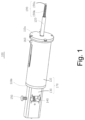
- FIG. 1 is a schematic perspective view illustrating a surgical power drill system according to the first exemplary embodiment of the present disclosure.
- FIG. 2 is a schematic cross-sectional view illustrating a state where a driving unit of the surgical power drill system of FIG. 1 is at a distal position according to the first exemplary embodiment of the present disclosure.
- FIG. 3 is a schematic exploded view illustrating the surgical power drill system of FIG. 1 according to the first exemplary embodiment of the present disclosure.
- FIG. 4 is a partial schematic cross-sectional view illustrating a state where the driving unit of the surgical power drill system of FIG. 1 is at a proximate position according to the first exemplary embodiment of the present disclosure.
- FIG. 5 is a partial schematic cross-sectional view illustrating a state where an engaging member of the surgical power drill system of FIG. 1 is at a disengaged position according to the first exemplary embodiment of the present disclosure.
- FIG. 6 is a schematic cross-sectional view illustrating a state where the engaging member of the surgical power drill system of FIG. 1 is at an engaged position according to the first exemplary embodiment of the present disclosure.
- FIG. 7 is a schematic diagram illustrating an on/off switch of the surgical power drill system of FIG. 1 according to the first exemplary embodiment of the present disclosure.
- FIG. 8 is a schematic perspective view illustrating a surgical power drill system according to the second exemplary embodiment of the present disclosure.
- FIG. 9 is a schematic diagram illustrating an on/off switch and an engaging member switch of the surgical power drill system of FIG. 8 according to the second exemplary embodiment of the present disclosure.
- FIG. 10 is a partial schematic cross-sectional view illustrating a surgical power drill system according to the third exemplary embodiment of the present disclosure.
- FIG. 11 is a schematic cross-sectional view illustrating a state where a driving unit of the surgical power drill system of FIG. 10 is at a distal position according to the third exemplary embodiment of the present disclosure.
- FIG. 12 is a schematic cross-sectional view illustrating a state where a driving unit of the surgical power drill system of FIG. 10 is beyond a proximate position according to the third exemplary embodiment of the present disclosure.
- FIG. 13 is a schematic diagram illustrating an on/off switch and a driving unit switch of the surgical power drill system of FIG. 10 according to the third exemplary embodiment of the present disclosure.
- FIG. 14 is a schematic perspective view illustrating a surgical power drill system according to the fourth exemplary embodiment of the present disclosure.
- FIG. 15 is a schematic diagram illustrating an on/off switch, a driving unit switch, and an engaging member switch of the surgical power drill system of FIG. 14 according to the fourth exemplary embodiment of the present disclosure.
- FIG. 16 is a schematic top view illustrating a surgical power drill system according to the fifth exemplary embodiment of the present disclosure.
- FIG. 17 is a partial schematic top view illustrating a surgical power drill system according to the sixth exemplary embodiment of the present disclosure.
- FIG. 18 is a partial schematic top view illustrating a surgical power drill system according to the seventh exemplary embodiment of the present disclosure.
- FIG. 19 is a schematic block diagram illustrating a surgery system according to an exemplary embodiment of the present disclosure.
- FIG. 1 is a schematic perspective view illustrating a surgical power drill system 100 according to the first exemplary embodiment of the present disclosure.
- the surgical power drill system 100 is suitable for use in surgical grinding/drilling procedures, e.g., orthopedic and plastic surgery procedures, or in any non-surgical grinding/drilling procedures.
- the surgical power drill system 100 includes a drill housing 110 , a tool holder 120 , a housing extension 130 , a screw member 140 , an engaging member 150 , and an on/off switch 160 .
- the drill housing 110 and the extension housing 130 constitute a housing unit 170 .
- the drill housing 110 accommodates therein a driving unit, e.g., driving unit 200 of FIG. 2 .
- the drill housing 110 is generally cylindrical.
- the drill housing 110 has a polygonal cross-section, such as rectangular.
- the drill housing 110 includes a front end 110 a and a rear end 110 b opposite to the front end 110 a .
- the front and rear ends 110 a , 110 b are fixedly mounted on the opposite ends of the drill housing 110 , respectively, such as by welding.
- the front and rear ends 110 a , 110 b are integral with the drill housing 110 .
- the front and rear ends 110 a , 110 b are detachably mounted on the opposite ends of the drill housing 110 , respectively, such as by a snap engagement.
- the tool holder 120 e.g., a drill chuck, is connected to the driving unit 200 , extends from the inside of the drill housing 110 through the front end 110 a of the drill housing 110 , and is configured to hold a tool bit 190 , e.g., a burr screw.
- the tool bit 190 includes a grinding portion 190 a that is at a tip thereof and that is suitable for grinding an object and an elongate drilling portion 190 b that extends from the grinding portion 190 a and that is suitable for drilling a hole in an object, such as a bone of a patient.
- the housing extension 130 is connected detachably to the rear end 110 b of the drill housing 110 and accommodates therein the screw member 140 , e.g., a lead screw, a ball screw, or the like.
- the housing extension 130 is integral with the drill housing 110 .
- the engaging member 150 is movably mounted on the housing extension 130 and includes a body member, e.g., body member 260 of FIG. 2 , a head member, e.g., head member 270 , a neck member, e.g., neck member 280 , and a biasing member, e.g., biasing member 290 .
- the body member 260 is disposed inside the housing extension 130 and is formed with a thread 260 ′ at a bottom surface thereof.
- the head member 270 is external to the housing unit 170 .
- the neck member 280 extends through the housing extension 130 , interconnects the body member 260 and the head member 270 , and has a smaller width than the body and head members 260 , 270 .
- the biasing member 290 is in the form of a spring, sleeved on the neck member 280 , and has opposite ends that abut the head member 270 and the housing extension 130 , respectively.
- the on/off switch 160 is mounted on the drill housing 110 and is electrically connected to the driving unit 200 .
- FIG. 2 is a schematic cross-sectional view illustrating a state where the driving unit 200 of the surgical power drill system 100 is at a distal position according to the first exemplary embodiment of the present disclosure.
- FIG. 3 is a schematic exploded view illustrating the surgical power drill system 100 according to the first exemplary embodiment of the present disclosure.
- FIG. 4 is a partial schematic cross-sectional view illustrating a state where the driving unit 200 of the surgical power drill system 100 is at a proximate position according to the first exemplary embodiment of the present disclosure.
- the surgical power drill system 100 further includes the driving unit 200 , a coupler 230 , a support member 240 , and a biasing member 250 .
- the driving unit 200 is movably disposed in the drill housing 110 and includes a motor, e.g., motor 750 of FIG. 7 , and a motor casing 210 that houses the motor 750 .
- the motor casing 210 may have a cross-section that corresponds to the cross-section of the drill housing 110 . In other embodiments, the motor casing 210 may have a cross-section different from the cross-section of the drill housing 110 .
- the motor 750 includes a rotor 210 ′ rotatably mounted on the motor casing 210 about a shaft axis (A), a stator (not shown) that is fixedly mounted on the motor casing 210 and that surrounds the rotor 210 ′, and a motor shaft 220 connected to the rotor 210 ′ and co-rotatable therewith about the shaft axis (A).
- the motor shaft 220 includes a first end portion 220 a that extends from the inside of the motor casing 210 through a front end 210 a of the motor casing 210 and that is connected to the tool holder 120 and a second end portion 220 b that extends from the inside of the motor casing 210 through a rear end 210 b of the motor casing 210 and that is connected to the screw member 140 .
- the coupler 230 interconnects the second end portion 220 b of the motor shaft 220 and the screw member 140 such that the screw member 140 extends along the shaft axis (A) and is co-rotatable with the motor shaft 220 about the shaft axis (A).
- the coupler 230 is sleeved on the second end portion 220 b of the motor shaft 220 and the screw member 140 .
- the coupler 230 may be made from a material with a low coefficient of friction, such as plastic.
- the motor shaft 220 is integral with the screw member 140 .
- the motor shaft 220 and the screw member 140 are formed into one piece.
- the surgical power drill system 100 is dispensed with the coupler 230 .
- the support member 240 is mounted in the housing extension 130 , is sleeved on the screw member 140 , and is configured to smoothen rotation and movement of the screw member 140 about and along the shaft axis (A).
- the engaging member 150 is between the coupler 230 and the support member 240 .
- the coupler 230 is between the drill housing 110 and the support member 240 .
- the surgical power drill system 100 further includes a fixing member 231 mounted on the front end 110 a of the drill housing 110 , sleeved on the tool holder 120 , and configured to minimize friction between the tool holder 120 and the drill housing 110 .
- a fixing member 231 mounted on the front end 110 a of the drill housing 110 , sleeved on the tool holder 120 , and configured to minimize friction between the tool holder 120 and the drill housing 110 .
- Such friction causes the tool holder 120 to wear, resulting in misaligning of the first end portion 220 a of the motor shaft 220 , the tool holder 120 , and/or the tool bit 190 with the shaft axis (A).
- the fixing member 231 is made from a material with a low coefficient of friction, such as plastic.
- the driving unit 200 is movable relative to the drill housing 110 between a distal position, where the motor casing 210 is distal from the front end 110 a of the drill housing 110 , as illustrated in FIG. 2 , and a proximate position, where the motor casing 210 is proximate to the front end 110 a of the drill housing 110 , as illustrated in FIG. 4 .
- a tip of the tool holder 120 is proximate to the front end 110 a of the drill housing 110 , as illustrated in FIG. 2 .
- the tip of the tool holder 120 is distal from the front end 110 a of the drill housing 110 , as shown in FIG. 4 .
- the coupler 230 is in the housing extension 130 , as shown in FIG. 2 .
- the coupler 230 is in the drill housing 110 , as shown in FIG. 4 .
- the rear end 210 b of the motor casing 210 abuts the rear end 110 b of the drill housing 110 , as shown in FIG. 2 .
- the rear end 210 b of the motor casing 210 is spaced from the rear end 110 b of the drill housing 110 , as shown in FIG. 4 .
- the tool holder 120 is connected to the first end portion 220 a of the motor shaft 220 such that the tool holder 120 extends along the shaft axis (A) and is co-rotatable with the motor shaft 220 about the shaft axis (A).
- the tool holder 120 , the screw member 140 , and the motor shaft 220 are tubular and in fluid communication with each other.
- the construction as such permits injection of a synthetic material, e.g., bone cement, by an instrument into an object, e.g., bone of a patient, through the screw member 140 , the motor shaft 220 , and the tool holder 120 .
- the biasing member 250 is configured to bias the driving unit 200 to the distal position.
- the biasing member 250 is in the form of a spring, is sleeved on the tool holder 120 and the first end portion 220 a of the motor shaft 220 , and has opposite ends that abut the front end 110 a of the drill housing 110 and the front end 210 a of the motor casing 210 , respectively.
- the biasing member 250 is further configured to prevent shaking of the driving unit 200 in the drill housing 110 .
- the biasing member 250 has a spring constant of k greater than or equal to a weight of the driving unit 200 . The construction as such permits stable movement of the driving unit 200 between the distal and proximate positions.
- biasing member 250 It should be understood that, after reading the present disclosure, other configurations of the biasing member 250 are contemplated as being within the scope of the present disclosure so long as its intended function is achieved.
- the drill housing 110 or the motor casing 210 or both the drill housing 110 and the motor casing 210 is/are magnetic.
- the drill housing 110 or the motor casing 210 or both the drill housing 110 and the motor casing 210 may be a magnet.
- the drill housing 110 or the motor casing 210 or both the drill housing 110 and the motor casing 210 may be magnetized, e.g., by an electric current or external magnetic field. The construction as such enhances prevention of the shaking of the driving unit 200 in the drill housing 110 .
- FIG. 5 is a partial schematic cross-sectional view illustrating a state where the engaging member 150 of the surgical power drill system 100 is at a disengaged position according to the first exemplary embodiment of the present disclosure.
- FIG. 6 is a schematic cross-sectional view illustrating a state where the engaging member 150 of the surgical power drill system 100 is at an engaged position according to the first exemplary embodiment of the present disclosure.
- the engaging member 150 is movable relative to the housing extension 130 between a disengaged position, where the thread 260 ′ of the body member 260 disengages the screw member 140 , as illustrated in FIG. 5 , and an engaged position, where the thread 260 ′ of the body member 260 engages the screw member 140 , as illustrated in FIG. 6 .
- the biasing member 290 is configured to bias the engaging member 150 from the engaged position to the disengaged position.
- biasing member 290 is contemplated as being within the scope of the present disclosure so long as its intended function is achieved.
- the surgical power drill system 100 of the present disclosure is exemplified with the thread 260 ′ formed on the bottom surface of the engaging member 150 , it should be understood that, after reading the present disclosure, the thread 260 ′ may be located anywhere on the engaging member 150 so long as it engages/disengages the screw member 140 when the engaging member 150 is moved to the engaged/disengaged position.
- the housing extension 130 is formed with first and second through holes 131 , 132 that form a stepped hole.
- the first through hole 131 is above the second through hole 132 , is in spatial communication with the second through hole 132 , and has a larger diameter than the second through hole 132 .
- the biasing member 290 is partially received in the first through hole 131 .
- the neck member 280 includes a first end portion 281 that extends through the first and second through holes 131 , 132 and a second end portion 282 that is in the housing extension 130 and that has a larger diameter than the second through hole 132 .
- the construction as such prevents undesired removal of the engaging member 150 from the housing extension 130 .
- a first input voltage is applied across the motor 750 and the motor 750 has a first rotational speed, e.g., about 6000 rpm or above.
- a second input voltage is applied across the motor 750 and the motor 750 has a second rotational speed, e.g., about 300 rpm or below, smaller than the first rotational speed.
- the motor 750 when the on/off switch 160 is switched on and the engaging member 150 is at the disengaged position, the motor 750 has a first torque, e.g., about 10 mNm or above. When the on/off switch 160 is switched on and the engaging member 150 is at the engaged position, the motor 750 has a second torque, e.g., about 100 mNm or above, larger than the first torque.
- FIG. 7 is a schematic diagram illustrating the on/off switch 160 of the surgical power drill system 100 according to the first exemplary embodiment of the present disclosure.
- the on/off switch 160 includes a first switch terminal 161 electrically connected to a positive terminal 720 of the surgical power drill system 100 and a second switch terminal 162 electrically connected to a first motor terminal 751 of the motor 750 .
- the motor 750 further includes a second motor terminal 752 electrically connected to a negative terminal 770 of the surgical power drill system 100 .
- the positive and negative terminals 720 , 770 are configured to be electrically connected to positive and negative terminals of a power source, e.g., battery, respectively.
- a shank of a tool bit 190 e.g., a burr screw
- a tip of the tool bit 190 is aligned with and pressed against a marked location on the object.
- a switch actuator of the on/off switch 160 is depressed, thereby turning the motor 750 on.
- the motor shaft 220 rotates, resulting in co-rotation of the tool holder 120 as well as the tool bit 190 , thereby grinding the object.
- the engaging member 150 is moved from the disengaged position, as shown in FIG. 5 , to the engaged position, as shown in FIG. 6 .
- the driving unit 200 moves from the distal position, as shown in FIG. 2 , to the proximate position, as shown in FIG. 4 , whereby a hole is drilled in the object.
- the surgical power drill system 100 of the present disclosure includes a motor shaft 220 connected to a screw member 140 such that each of the motor shaft 220 and the screw member 140 extends along a shaft axis (A) and an engaging member 150 that engages the screw member 140 to cause movement of a driving unit 200 in a drill housing 110 . Therefore, the surgical power drill system 100 of the present disclosure has a simple structure, a compact size, and a reduced weight.
- FIG. 8 is a schematic perspective view illustrating a surgical power drill system 800 according to the second exemplary embodiment of the present disclosure.
- the surgical power drill system 800 differs from the surgical power drill system 100 in that the surgical power drill system 800 further includes an engaging member switch 810 mounted on the housing extension 130 and electrically connected to a motor, e.g., motor 750 , of a driving unit, e.g., driving unit 200 , of the surgical power drill system 800 .
- the engaging member switch 810 includes a switch actuator that protrudes from the housing extension 130 and that is arranged adjacent the neck member, e.g., neck member 280 , and under the head member, e.g., head member 270 .
- the construction as such permits the engaging member 150 to switch the engaging member switch 810 on and off when the engaging member 150 moves between the engaged and disengaged positions, respectively.
- the engaging member switch 810 is mounted on, e.g., attached to an outer surface of or embedded in, the engaging member 150 so as to be co-movable therewith and the switch actuator thereof is switched on and off when the engaging member 150 moves between the engaged and disengaged positions, respectively.
- FIG. 9 is a schematic diagram illustrating the on/off switch 160 and the engaging member switch 810 of the surgical power drill system 800 according to the second exemplary embodiment of the present disclosure.
- the on/off switch 160 includes a first switch terminal 161 electrically connected to a positive terminal 920 of the surgical power drill system 800 and a second switch terminal 162 electrically connected to a first motor terminal 751 of the motor 750 of the surgical power drill system 800 .
- the motor 750 further includes a second motor terminal 752 electrically connected to a negative terminal 970 of the surgical power drill system 800 .
- the positive and negative terminals 920 , 970 of the surgical power drill system 800 are configured to be connected to positive and negative terminals of a power source, e.g., battery, respectively.
- the engaging member switch 810 is in parallel with the on/off switch 160 .
- the engaging member switch 810 includes first and second switch terminals 811 , 812 electrically and respectively connected to the first and second switch terminals 161 , 162 of the on/off switch 160 .
- a shank of a tool bit 190 e.g., a burr screw
- a tip of the tool bit 190 is aligned with and pressed against a marked location on the object.
- the switch actuator of the on/off switch 160 is depressed, thereby turning the motor 750 on.
- the motor shaft 220 rotates, resulting in co-rotation of the tool holder 120 as well as the tool bit 190 , thereby grinding the object.
- the switch actuator of the on/off switch 160 is switched off.
- the engaging member 150 is moved from the disengaged position, as shown in FIG. 5 , to the engaged position, as shown in FIG. 6 .
- This switches on the switch actuator of the engaging member switch 810 by the head member 270 of the engaging member 150 , thereby switching the motor 750 on.
- This rotates the motor shaft, e.g., motor shaft 220 , resulting in co-rotation of the tool holder 120 as well as the tool bit 190 .
- the driving unit e.g., driving unit 200 , moves from the distal position, as shown in, e.g., FIG. 2 , to the proximate position, as shown in, e.g., FIG. 4 , whereby a hole is drilled in the object.
- the switch actuator of the engaging member switch 810 is switched on by the engaging member 150 .
- drilling may be performed by simply moving the engaging member 150 to the engaged position, i.e., without the need to depress the switch actuator of the on/off switch 160 , making operation of the surgical power drill system 800 of the present disclosure relatively easy.
- FIG. 10 is a partial schematic cross-sectional view illustrating a surgical power drill system 1000 according to the third exemplary embodiment of the present disclosure.
- FIG. 11 is a schematic cross-sectional view illustrating a state where the driving unit 200 of the surgical power drill system 1000 is at a distal position according to the third exemplary embodiment of the present disclosure.
- FIG. 12 is a schematic cross-sectional view illustrating a state where the driving unit 200 of the surgical power drill system 1000 is beyond the proximate position according to the third exemplary embodiment of the present disclosure. As illustrated in FIG.
- the surgical power drill system 1000 differs from the surgical power drill system 100 in that the surgical power drill system 1000 further includes a driving unit switch 1010 mounted on the drill housing 110 and electrically connected to a motor, e.g., motor 750 , of a driving unit, e.g., driving unit 200 , of the surgical power drill system 1000 .
- the driving unit switch 1010 includes a switch actuator 1030 that extends into the drill housing 110 .
- the biasing member 250 is configured to bias the driving unit 200 to an initial position between the distal and proximate positions.
- a first protruding member 1020 protrudes from the motor casing 210 , e.g., from a top surface of the motor casing 210 , at the front end 210 a of the motor casing 210 .
- the first protruding member 1020 is configured to switch on the switch actuator 1030 of the driving unit switch 1010 when the driving unit 200 moves to the distal position, as illustrated in FIG. 11 .
- a second protruding member 1040 protrudes from the motor casing 210 , e.g., from the top surface of the motor casing 210 , between the front and rear ends 210 a , 210 b of the motor casing 210 .
- the second protruding member 1040 is configured to switch off the switch actuator 1030 of the driving unit switch 1010 when the driving unit 200 moves beyond the proximate position, as illustrated in FIG. 12 .
- a distance between the first and second protruding members 1020 , 1040 is, e.g., from about 30 mm to about 70 mm.
- the surgical power drill system 1000 includes a single protruding member that protrudes from the motor casing 210 and that is configured to switch on and off the driving unit switch 1010 when the driving unit 200 moves to the distal position and beyond the proximate position, respectively.
- the surgical power drill system 1000 is dispensed with the first and second protruding members 1020 , 1040 .
- the driving unit switch 1010 is switched on by the rear end 210 b of the motor casing 210 when the driving unit 200 moves to the distal position and is switched off by the front end 210 a of the motor casing 210 when the driving unit 200 moves beyond the proximate position.
- FIG. 13 is a schematic diagram illustrating the on/off switch 160 and the driving unit switch 1010 of the surgical power drill system 1000 according to the third exemplary embodiment of the present disclosure.
- the driving unit switch 1010 is in series with the on/off switch 160 .
- the driving unit switch 1010 has a first switch terminal 1011 electrically connected to the positive terminal 1320 of the surgical power drill system 1000 and a second switch terminal 1012 electrically connected to a first switch terminal 161 of the on/off switch 160 .
- the on/off switch 160 further includes a second switch terminal 162 electrically connected to a first motor terminal 751 of the motor 750 .
- the motor 750 further includes a second motor terminal 752 electrically connected to a negative terminal 1390 of the surgical power drill system 1000 .
- the positive and negative terminals 1320 , 1390 of the surgical power drill system 1000 are configured to be connected to positive and negative terminals of a power source, e.g., battery, respectively.
- a shank of a tool bit 190 e.g., a burr screw
- a tip of the tool bit 190 is aligned with and pressed against a marked location on the object.
- This moves the driving unit 200 from an initial position between the distal and proximate positions, as shown in FIG. 10 , to the distal position, as shown in FIG. 11 .
- This switches on the switch actuator 1030 of the driving unit switch 1010 by the first protruding member 1020 .
- the switch actuator of the on/off switch 160 is depressed, thereby turning the motor 750 on.
- the motor shaft 220 rotates, resulting in co-rotation of the tool holder 120 , thereby grinding the object.
- the engaging member 150 is moved from the disengaged position, as shown in, e.g., FIG. 5 , to the engaged position, as shown in, e.g., FIG. 6 .
- the second protruding member 1040 switches off the switch actuator 1030 of the driving unit switch 1010 .
- the motor 750 is turned off, stopping the drilling procedure. The construction as such prevents the surgical power drill system 1000 of the present disclosure from making a hole in an undesired location of the object.
- FIG. 14 is a schematic perspective view illustrating a surgical power drill system 1400 according to the fourth exemplary embodiment of the present disclosure.
- the surgical power drill system 1400 differs from the surgical power drill system 1000 in that the surgical power drill system 1400 further includes an engaging member switch 1410 mounted on the housing extension 130 and electrically connected to a motor, e.g., motor 750 of a driving unit, e.g., driving unit 200 , of the surgical power drill system 1400 .
- a motor e.g., motor 750 of a driving unit, e.g., driving unit 200
- the engaging member switch 1410 includes a switch actuator that protrudes from the housing extension 130 , e.g., from a top surface of the housing extension 130 , and that is arranged adjacent a neck member, e.g., neck member 280 , under a head member, e.g., head member 270 .
- the construction as such permits the engaging member 150 to switch the engaging member switch 1410 on and off when the engaging member 150 moves between the engaged and disengaged positions, respectively.
- the engaging member switch 1410 is mounted on, e.g., attached to an outer surface of or embedded in, the engaging member 150 so as to be co-movable therewith and the switch actuator thereof is switched on and off when the engaging member 150 moves between the engaged and disengaged positions, respectively.
- FIG. 15 is a schematic diagram illustrating the on/off switch 160 , the driving unit switch 1010 , and the engaging member switch 1410 of the surgical power drill system 1400 according to the fourth exemplary embodiment of the present disclosure.
- the driving unit switch 1010 is in series with the on/off switch 160 .
- the driving unit switch 1010 has a first switch terminal 1011 electrically connected to a positive terminal 1520 of the surgical power drill system 1400 and a second switch terminal 1012 electrically connected to a first switch terminal 161 of the on/off switch 160 .
- the on/off switch 160 further includes a second switch terminal 162 electrically connected to a first motor terminal 751 of the motor 750 .
- the motor 750 further includes a second motor terminal 752 electrically connected to a negative terminal 1590 of the surgical power drill system 1400 .
- the positive and negative terminals 1520 , 1590 of the surgical power drill system 1400 are configured to be connected to positive and negative terminals of a power source, e.g., battery, respectively.
- the engaging member switch 1410 is in parallel with the on/off switch 160 .
- the engaging member switch 1410 includes first and second switch terminals 1411 , 1412 electrically and respectively connected to the first and second switch terminals 161 , 162 of the on/off switch 160 .
- a shank of a tool bit 190 e.g., a burr screw
- a tip of the tool bit 190 is aligned with and pressed against a marked location on the object.
- This moves the driving unit 200 from an initial position between the distal and proximate positions, as shown in, e.g., FIG. 10 , to the distal position, as shown in, e.g., FIG. 11 .
- This switches on the switch actuator 1030 of the driving unit switch 1010 by the first protruding member 1020 .
- the switch actuator of the on/off switch 160 is depressed, thereby turning the motor 750 on.
- the motor shaft e.g., motor shaft 220
- the switch actuator of the on/off switch 160 is switched off.
- the engaging member 150 is moved from the disengaged position, as shown in, e.g., FIG. 5 , to the engaged position, as shown in, e.g., in FIG. 6 .
- This switches on the switch actuator of the engaging member switch 1410 by the head member 270 of the engaging member 150 , thereby turning the motor 750 on.
- This rotates the motor shaft, e.g., motor shaft 220 , resulting in co-rotation of the tool holder 120 .
- the driving unit 200 moves from the distal position, as shown in, e.g., FIG. 11 , to the proximate position, whereby a hole is drilled in the object.
- the second protruding member e.g., second protruding member 1040
- switches off the switch actuator e.g., switch actuator 1030
- the motor 750 is turned off, stopping the drilling procedure. The construction as such prevents the surgical power drill system 1400 of the present disclosure from making a hole in an undesired location of the object.
- the switch actuator of the engaging member switch 1410 is switched on by the engaging member 150 .
- drilling may be performed by simply moving the engaging member 150 to the engaged position, i.e., without the need to depress the switch actuator of the on/off switch 160 , making operation of the surgical power drill system 1400 of the present disclosure relatively easy.
- switches 810 , 1010 , 1410 that have switch actuators, e.g., switch actuator 1030
- switch actuators e.g., switch actuator 1030
- other configurations of the switches 810 , 1010 , 1410 are contemplated as being within the scope of the present disclosure so long as their intended functions are achieved.
- at least one of the switches 810 , 1010 , 1410 may include a motion sensor, e.g., infrared, acoustic, magnetic, and the like, that detects a motion or change in the position of the engaging member 150 /driving unit 200 .
- FIG. 16 is a schematic top view illustrating a surgical power drill system 1600 according to the fifth exemplary embodiment of the present disclosure. As illustrated in FIG. 16 , this embodiment differs from the previous embodiments in that the surgical power drill system 1600 further includes a marker 1610 arranged on the motor casing 210 so as to be co-movable therewith and is exposed through a window 1620 in the drill housing 110 , thereby allowing tracking of positions of the motor casing 210 by a computer system via a spatial sensor, e.g., camera.
- a spatial sensor e.g., camera
- At least one of the motor casing 210 , the tool holder 120 , and the screw member 140 is provided with a marker, e.g., marker 1610 .
- the marker 1610 is an active marker.
- the signal emitted by the marker 1610 is generated by the marker 1610 itself.
- the marker 1610 is configured to emit an electromagnetic signal, a sound wave, a heat, any perceivable signal, or a combination thereof.
- the marker 1610 is a passive marker.
- the marker 1610 is covered with a reflective material and the signal emitted by the marker 1610 is a signal reflected thereby.
- the marker 1610 is an active and passive marker. In such certain embodiments, the marker 1610 is configured to generate a signal and is covered with a reflective material.
- FIG. 17 is a partial schematic top view illustrating a surgical power drill system 1700 according to the sixth exemplary embodiment of the present disclosure.
- the surgical power drill system 1700 differs from the surgical power drill system 1600 in that the surgical power drill system 1700 further includes a pair of markers 1710 , 1720 configured to absorb a radiation, such as an X-ray.
- markers 1710 , 1720 include, but are not limited to, metals and ceramics.
- the markers 1710 , 1720 are arranged on the tool holder 120 of the surgical power drill system 1700 along the shaft axis (A) of the surgical power drill system 1700 , thereby allowing tracking of positions of the tool holder 120 by, e.g., an X-ray imaging system.
- At least one of the markers 1710 , 1720 is an active marker.
- the signal emitted by the at least one of the markers 1710 , 1720 is generated by the at least one of the markers 1710 , 1720 itself.
- one or both of the markers 1710 , 1720 are configured to emit an electromagnetic signal, a sound wave, a heat, any perceivable signal, or a combination thereof.
- at least one of the markers 1710 , 1720 is a passive marker.
- the at least one of the markers 1710 , 1720 is covered with a reflective material and the signal emitted by the at least one of the markers 1710 , 1720 is a signal reflected thereby.
- At least one of the markers 1710 , 1720 is an active and passive marker. In such certain embodiments, the at least one of the markers 1710 , 1720 is configured to generate a signal and is covered with a reflective material.
- FIG. 18 is a partial schematic top view illustrating a surgical power drill system 1800 according to the seventh exemplary embodiment of the present disclosure.
- the surgical power drill system 1800 differs from the surgical power drill system 1600 in that the surgical power drill system 1800 further includes a pair of markers 1810 , 1820 configured to absorb a radiation, such as an X-ray.
- Examples of materials for the markers 1810 , 1820 include, but are not limited to, metals and ceramics.
- the markers 1810 , 1820 are arranged on opposite sides of the tool holder 120 , respectively. At least one of the markers 1810 , 1820 is movable along the length of the tool holder 120 .
- one of the markers 1810 , 1820 is fixedly mounted on the tool holder 120 and the other of the markers 1810 , 1820 is movable along the length of the tool holder 120 .
- both the markers 1810 , 1820 are movable along the length of the tool holder 120 .
- the surgical power drill system 1800 further includes a set of angle indicia 1830 that is arranged on the tool holder 120 and that measures an angle (a) between the shaft axis (A) and a line (B) that intersects the markers 1810 , 1820 .
- one or both of the markers 1810 , 1820 are adjusted with reference to the angle indicia 1830 such that a marker angle is formed therebetween.
- the surgical power drill system 1800 is brought in contact with an object, e.g., a bone of a patient, such that a contact angle is formed therebetween.
- an image, e.g., an X-ray image, of the surgical power drill system 1800 and the object is taken to confirm whether the contact angle corresponds to the marker angle.
- At least one of the markers 1810 , 1820 is an active marker.
- the signal emitted by the at least one of the markers 1810 , 1820 is generated by the at least one of the markers 1810 , 1820 itself.
- one or both of the markers 1810 , 1820 is configured to emit an electromagnetic signal, a sound wave, a heat, any perceivable signal, or a combination thereof.
- at least one of the markers 1810 , 1820 is a passive marker.
- the at least one of the markers 1810 , 1820 is covered with a reflective material and the signal emitted by the at least one of the markers 1810 , 1820 is a signal reflected thereby.
- At least one of the markers 1810 , 1820 is an active and passive marker. In such certain embodiments, the at least one of the markers 1810 , 1820 is configured to generate a signal and is covered with a reflective material.
- an instrument e.g., a robotic arm
- the surgical power drill system 100 , 800 , 1000 , 1400 , 1600 , 1700 , 1800 , 1700 , or 1800 may be used to control movements and operations of the surgical power drill system 100 , 800 , 1000 , 1400 , 1600 , 1700 , 1800 , 1700 , or 1800 .
- FIG. 19 is a schematic block diagram illustrating a surgery system 1900 according to an exemplary embodiment of the present disclosure.
- the surgery system 1900 e.g., an orthopedic surgery system
- the surgical power drill system 1920 may be one of the surgical power drill systems 100 , 800 , 1000 , 1400 , 1600 , 1700 , 1800 .
- the controller 1910 is connected to and configured to control movements and operations of the surgical power drill system 1920 .
- a surgical power drill system comprises a housing unit, a driving unit, a tool holder, and a screw member.
- the driving unit is movably mounted in the housing unit and includes a motor and a motor shaft coupled to the motor.
- the driving unit is movable relative to the housing unit between a distal position, where the driving unit is distal from a front end of the housing unit, and a proximate position, where the driving unit is proximate to the front end of the housing unit.
- the tool holder is coupled to a first end portion of the motor shaft.
- the screw member is coupled to a second end portion of the motor shaft.
- a surgical power drill system comprises a housing unit, a driving unit, a tool holder, and a driving unit switch.
- the driving unit is movably mounted in the housing unit and includes a motor and a motor shaft coupled to the motor.
- the tool holder is coupled to a first end portion of the motor shaft.
- the driving unit switch is coupled to the motor and is configured to be switched on and off by the driving unit.
- a surgical power drill system comprises a housing unit, a driving unit, a tool holder, and engaging member.
- the driving unit is movably mounted in the housing unit and includes a motor and a motor shaft coupled to the motor.
- the driving unit is movable relative to the housing unit between a distal position, where the driving unit is distal from a front end of the housing unit, and a proximate position, where the driving unit is proximate to the front end of the housing unit.
- the tool holder is coupled to a first end portion of the motor shaft.
- the engaging member extends into the housing unit and is configured to engage the motor shaft to move the driving unit to the proximate position.
Landscapes
- Health & Medical Sciences (AREA)
- Surgery (AREA)
- Life Sciences & Earth Sciences (AREA)
- Biomedical Technology (AREA)
- Medical Informatics (AREA)
- Veterinary Medicine (AREA)
- Oral & Maxillofacial Surgery (AREA)
- Engineering & Computer Science (AREA)
- Public Health (AREA)
- Heart & Thoracic Surgery (AREA)
- Nuclear Medicine, Radiotherapy & Molecular Imaging (AREA)
- Molecular Biology (AREA)
- Animal Behavior & Ethology (AREA)
- General Health & Medical Sciences (AREA)
- Dentistry (AREA)
- Orthopedic Medicine & Surgery (AREA)
- Pathology (AREA)
- Surgical Instruments (AREA)
Abstract
Description
Claims (17)
Priority Applications (1)
| Application Number | Priority Date | Filing Date | Title |
|---|---|---|---|
| US17/317,924 US11903591B2 (en) | 2021-05-12 | 2021-05-12 | Surgical power drill system |
Applications Claiming Priority (1)
| Application Number | Priority Date | Filing Date | Title |
|---|---|---|---|
| US17/317,924 US11903591B2 (en) | 2021-05-12 | 2021-05-12 | Surgical power drill system |
Publications (2)
| Publication Number | Publication Date |
|---|---|
| US20220361897A1 US20220361897A1 (en) | 2022-11-17 |
| US11903591B2 true US11903591B2 (en) | 2024-02-20 |
Family
ID=83999202
Family Applications (1)
| Application Number | Title | Priority Date | Filing Date |
|---|---|---|---|
| US17/317,924 Active 2042-04-07 US11903591B2 (en) | 2021-05-12 | 2021-05-12 | Surgical power drill system |
Country Status (1)
| Country | Link |
|---|---|
| US (1) | US11903591B2 (en) |
Cited By (1)
| Publication number | Priority date | Publication date | Assignee | Title |
|---|---|---|---|---|
| US20240237994A1 (en) * | 2021-09-28 | 2024-07-18 | Spineguard | Universal adapter for handheld surgical systems |
Families Citing this family (1)
| Publication number | Priority date | Publication date | Assignee | Title |
|---|---|---|---|---|
| AU2023231283A1 (en) * | 2022-03-10 | 2024-09-19 | Pro-Dex, Inc. | Surgical impactor |
Citations (8)
| Publication number | Priority date | Publication date | Assignee | Title |
|---|---|---|---|---|
| US20090326537A1 (en) * | 2008-06-26 | 2009-12-31 | Wayne Anderson | Depth controllable and measurable medical driver devices and methods of use |
| US20150078849A1 (en) * | 2013-09-19 | 2015-03-19 | Soteria lndustries, lnc. | Collapsible drill and associated methods of use |
| US20160206328A1 (en) * | 2015-01-21 | 2016-07-21 | Soteria Industries Inc. | Surgical drill |
| US10245043B2 (en) * | 2013-07-09 | 2019-04-02 | Stryker Corporation | Surgical drill having a brake that, upon the drill bit penetrating through bone, prevents further insertion of the drill |
| US10695074B2 (en) * | 2015-09-03 | 2020-06-30 | Stryker Corporation | Powered surgical drill with integral depth gauge that includes a probe that slides over the drill bit |
| US20200330116A1 (en) * | 2019-04-22 | 2020-10-22 | Medos International Sarl | Bone and tissue resection devices and methods |
| US20200367989A1 (en) * | 2019-05-20 | 2020-11-26 | Peter L. Bono | Retracting tool for robotic surgery |
| US20230293189A1 (en) * | 2022-03-16 | 2023-09-21 | Peninsula Surgical Solutions, Llc | Medical drill and implant device and method of using the same |
-
2021
- 2021-05-12 US US17/317,924 patent/US11903591B2/en active Active
Patent Citations (8)
| Publication number | Priority date | Publication date | Assignee | Title |
|---|---|---|---|---|
| US20090326537A1 (en) * | 2008-06-26 | 2009-12-31 | Wayne Anderson | Depth controllable and measurable medical driver devices and methods of use |
| US10245043B2 (en) * | 2013-07-09 | 2019-04-02 | Stryker Corporation | Surgical drill having a brake that, upon the drill bit penetrating through bone, prevents further insertion of the drill |
| US20150078849A1 (en) * | 2013-09-19 | 2015-03-19 | Soteria lndustries, lnc. | Collapsible drill and associated methods of use |
| US20160206328A1 (en) * | 2015-01-21 | 2016-07-21 | Soteria Industries Inc. | Surgical drill |
| US10695074B2 (en) * | 2015-09-03 | 2020-06-30 | Stryker Corporation | Powered surgical drill with integral depth gauge that includes a probe that slides over the drill bit |
| US20200330116A1 (en) * | 2019-04-22 | 2020-10-22 | Medos International Sarl | Bone and tissue resection devices and methods |
| US20200367989A1 (en) * | 2019-05-20 | 2020-11-26 | Peter L. Bono | Retracting tool for robotic surgery |
| US20230293189A1 (en) * | 2022-03-16 | 2023-09-21 | Peninsula Surgical Solutions, Llc | Medical drill and implant device and method of using the same |
Cited By (2)
| Publication number | Priority date | Publication date | Assignee | Title |
|---|---|---|---|---|
| US20240237994A1 (en) * | 2021-09-28 | 2024-07-18 | Spineguard | Universal adapter for handheld surgical systems |
| US12569259B2 (en) * | 2021-09-28 | 2026-03-10 | Spineguard | Universal adapter for handheld surgical systems |
Also Published As
| Publication number | Publication date |
|---|---|
| US20220361897A1 (en) | 2022-11-17 |
Similar Documents
| Publication | Publication Date | Title |
|---|---|---|
| US11903591B2 (en) | Surgical power drill system | |
| JP7154350B2 (en) | Surgical instrument with telescopic nose mechanism | |
| US9655601B2 (en) | Ergonomic handpiece for laparoscopic and open surgery | |
| US6960894B2 (en) | Cordless, powered surgical tool | |
| US7804224B2 (en) | Piezoelectric motor and piezoelectric motor system | |
| US20080053805A1 (en) | Power tool | |
| US20170224403A1 (en) | Surgical treatment apparatus | |
| EP4255325A1 (en) | Non-rotational bone cutting tools and related systems and methods | |
| US11833642B2 (en) | Power tool with electrically controlled commutating assembly | |
| CN115337071B (en) | Surgical drill and orthopedic surgery system | |
| TWI797619B (en) | Surgical drill and orthopedic surgery system | |
| US20200361073A1 (en) | Magnetic base | |
| KR102285936B1 (en) | Power tool for orthopedic surgery | |
| ES2243778T3 (en) | MOTORIZED CUTTING TOOL WITH AN AUTOMATIC CUTTING DEVICE. | |
| AU2022201173A1 (en) | Non-contact direction selector mechanism | |
| JP2006096130A (en) | Mirror and angle detecting device | |
| WO2005032772A1 (en) | Origin adjusting device of industrial robot | |
| CN221206549U (en) | A detection mechanism and ultrasonic treatment handpiece | |
| CN119587169B (en) | Rotation limiting structure and synchronous rotation method for interventional surgery robot | |
| JP2004273127A (en) | Switch unit and torque tool | |
| CN115817017A (en) | Actuator and inkjet printing apparatus including the same | |
| CN117180645A (en) | Detection mechanism and ultrasonic treatment hand tool | |
| JP3748502B2 (en) | Slider driving device for surface texture measuring machine | |
| US10182706B2 (en) | Insertion device treatment system | |
| HK40077919A (en) | Non-contact direction selector mechanism |
Legal Events
| Date | Code | Title | Description |
|---|---|---|---|
| FEPP | Fee payment procedure |
Free format text: ENTITY STATUS SET TO UNDISCOUNTED (ORIGINAL EVENT CODE: BIG.); ENTITY STATUS OF PATENT OWNER: SMALL ENTITY |
|
| FEPP | Fee payment procedure |
Free format text: ENTITY STATUS SET TO SMALL (ORIGINAL EVENT CODE: SMAL); ENTITY STATUS OF PATENT OWNER: SMALL ENTITY |
|
| STPP | Information on status: patent application and granting procedure in general |
Free format text: DOCKETED NEW CASE - READY FOR EXAMINATION |
|
| AS | Assignment |
Owner name: POINT ROBOTICS (SINGAPORE) PTE. LTD., SINGAPORE Free format text: ASSIGNMENT OF ASSIGNORS INTEREST;ASSIGNOR:POINT ROBOTICS MEDTECH INC.;REEL/FRAME:062848/0821 Effective date: 20230302 |
|
| STPP | Information on status: patent application and granting procedure in general |
Free format text: NON FINAL ACTION MAILED |
|
| STPP | Information on status: patent application and granting procedure in general |
Free format text: RESPONSE TO NON-FINAL OFFICE ACTION ENTERED AND FORWARDED TO EXAMINER |
|
| STPP | Information on status: patent application and granting procedure in general |
Free format text: FINAL REJECTION MAILED |
|
| STPP | Information on status: patent application and granting procedure in general |
Free format text: NOTICE OF ALLOWANCE MAILED -- APPLICATION RECEIVED IN OFFICE OF PUBLICATIONS |
|
| STPP | Information on status: patent application and granting procedure in general |
Free format text: PUBLICATIONS -- ISSUE FEE PAYMENT RECEIVED |
|
| STPP | Information on status: patent application and granting procedure in general |
Free format text: PUBLICATIONS -- ISSUE FEE PAYMENT VERIFIED |
|
| STCF | Information on status: patent grant |
Free format text: PATENTED CASE |