US11900669B2 - Calibration device and calibration method - Google Patents
Calibration device and calibration method Download PDFInfo
- Publication number
- US11900669B2 US11900669B2 US17/528,582 US202117528582A US11900669B2 US 11900669 B2 US11900669 B2 US 11900669B2 US 202117528582 A US202117528582 A US 202117528582A US 11900669 B2 US11900669 B2 US 11900669B2
- Authority
- US
- United States
- Prior art keywords
- imaging device
- image
- calibration
- field
- view
- Prior art date
- Legal status (The legal status is an assumption and is not a legal conclusion. Google has not performed a legal analysis and makes no representation as to the accuracy of the status listed.)
- Active, expires
Links
Images


Classifications
-
- H—ELECTRICITY
- H04—ELECTRIC COMMUNICATION TECHNIQUE
- H04N—PICTORIAL COMMUNICATION, e.g. TELEVISION
- H04N17/00—Diagnosis, testing or measuring for television systems or their details
- H04N17/002—Diagnosis, testing or measuring for television systems or their details for television cameras
-
- G—PHYSICS
- G06—COMPUTING OR CALCULATING; COUNTING
- G06V—IMAGE OR VIDEO RECOGNITION OR UNDERSTANDING
- G06V20/00—Scenes; Scene-specific elements
- G06V20/10—Terrestrial scenes
- G06V20/13—Satellite images
-
- H—ELECTRICITY
- H04—ELECTRIC COMMUNICATION TECHNIQUE
- H04N—PICTORIAL COMMUNICATION, e.g. TELEVISION
- H04N23/00—Cameras or camera modules comprising electronic image sensors; Control thereof
- H04N23/90—Arrangement of cameras or camera modules, e.g. multiple cameras in TV studios or sports stadiums
-
- G—PHYSICS
- G06—COMPUTING OR CALCULATING; COUNTING
- G06F—ELECTRIC DIGITAL DATA PROCESSING
- G06F16/00—Information retrieval; Database structures therefor; File system structures therefor
- G06F16/20—Information retrieval; Database structures therefor; File system structures therefor of structured data, e.g. relational data
- G06F16/29—Geographical information databases
-
- G—PHYSICS
- G06—COMPUTING OR CALCULATING; COUNTING
- G06F—ELECTRIC DIGITAL DATA PROCESSING
- G06F18/00—Pattern recognition
-
- G—PHYSICS
- G06—COMPUTING OR CALCULATING; COUNTING
- G06F—ELECTRIC DIGITAL DATA PROCESSING
- G06F18/00—Pattern recognition
- G06F18/20—Analysing
- G06F18/22—Matching criteria, e.g. proximity measures
-
- G—PHYSICS
- G06—COMPUTING OR CALCULATING; COUNTING
- G06F—ELECTRIC DIGITAL DATA PROCESSING
- G06F18/00—Pattern recognition
- G06F18/20—Analysing
- G06F18/23—Clustering techniques
- G06F18/231—Hierarchical techniques, i.e. dividing or merging pattern sets so as to obtain a dendrogram
-
- G—PHYSICS
- G06—COMPUTING OR CALCULATING; COUNTING
- G06V—IMAGE OR VIDEO RECOGNITION OR UNDERSTANDING
- G06V10/00—Arrangements for image or video recognition or understanding
- G06V10/10—Image acquisition
- G06V10/12—Details of acquisition arrangements; Constructional details thereof
- G06V10/14—Optical characteristics of the device performing the acquisition or on the illumination arrangements
- G06V10/147—Details of sensors, e.g. sensor lenses
-
- G—PHYSICS
- G06—COMPUTING OR CALCULATING; COUNTING
- G06V—IMAGE OR VIDEO RECOGNITION OR UNDERSTANDING
- G06V10/00—Arrangements for image or video recognition or understanding
- G06V10/20—Image preprocessing
- G06V10/22—Image preprocessing by selection of a specific region containing or referencing a pattern; Locating or processing of specific regions to guide the detection or recognition
-
- G—PHYSICS
- G06—COMPUTING OR CALCULATING; COUNTING
- G06V—IMAGE OR VIDEO RECOGNITION OR UNDERSTANDING
- G06V10/00—Arrangements for image or video recognition or understanding
- G06V10/70—Arrangements for image or video recognition or understanding using pattern recognition or machine learning
- G06V10/74—Image or video pattern matching; Proximity measures in feature spaces
-
- G—PHYSICS
- G06—COMPUTING OR CALCULATING; COUNTING
- G06V—IMAGE OR VIDEO RECOGNITION OR UNDERSTANDING
- G06V20/00—Scenes; Scene-specific elements
- G06V20/50—Context or environment of the image
- G06V20/52—Surveillance or monitoring of activities, e.g. for recognising suspicious objects
- G06V20/54—Surveillance or monitoring of activities, e.g. for recognising suspicious objects of traffic, e.g. cars on the road, trains or boats
-
- H—ELECTRICITY
- H04—ELECTRIC COMMUNICATION TECHNIQUE
- H04N—PICTORIAL COMMUNICATION, e.g. TELEVISION
- H04N23/00—Cameras or camera modules comprising electronic image sensors; Control thereof
- H04N23/60—Control of cameras or camera modules
-
- H—ELECTRICITY
- H04—ELECTRIC COMMUNICATION TECHNIQUE
- H04N—PICTORIAL COMMUNICATION, e.g. TELEVISION
- H04N23/00—Cameras or camera modules comprising electronic image sensors; Control thereof
- H04N23/60—Control of cameras or camera modules
- H04N23/698—Control of cameras or camera modules for achieving an enlarged field of view, e.g. panoramic image capture
-
- G—PHYSICS
- G01—MEASURING; TESTING
- G01S—RADIO DIRECTION-FINDING; RADIO NAVIGATION; DETERMINING DISTANCE OR VELOCITY BY USE OF RADIO WAVES; LOCATING OR PRESENCE-DETECTING BY USE OF THE REFLECTION OR RERADIATION OF RADIO WAVES; ANALOGOUS ARRANGEMENTS USING OTHER WAVES
- G01S7/00—Details of systems according to groups G01S13/00, G01S15/00, G01S17/00
- G01S7/48—Details of systems according to groups G01S13/00, G01S15/00, G01S17/00 of systems according to group G01S17/00
- G01S7/497—Means for monitoring or calibrating
- G01S7/4972—Alignment of sensor
Definitions
- the present invention relates to a calibration device and a calibration method, in each of which coordinate systems of imaging devices are integrated.
- Imaging devices may be installed in an autonomous robot in a work site in which information on a space such as a landform is constantly changing or in a building site in which BIM (Building Information Modeling) data on a building is acquired on a real-time basis.
- the imaging device has a high flexibility to change positions thereof (can freely move or change an orientation thereof), which requires a high-speed calibration.
- Patent Document 1 discloses a camera position detecting method that processes: a first step for photographing a plurality of cameras by a panoramic camera; a second step for controlling driving mechanisms to make the plurality of cameras operate; a third step for making the panoramic camera photograph the plurality of cameras, after the plurality of cameras are made to operate; a fourth step for processing data for specifying the plurality of cameras in photographed images on the basis of data on difference images acquired, by photographing the cameras before and after the plurality of cameras are made to operate; and a fifth step for processing data for computing the positions of the plurality of cameras, on the basis of images in which a plurality of specified cameras are photographed.
- Patent Document 2 discloses a stereo camera system that includes: a first and a second stereoscopic camera; a 3-D position calculating part for calculating a first and a second 3-D position of a person captured in the first and second stereoscopic images by the principle of stereoscopic view, based on the first and the second stereoscopic images; a region of projected person calculating part for forming the first and second images, including the first and second regions of projected person which correlate with the projected image of the person captured in the first and second stereoscopic images projected to the 2-D plane, based on the first and second 3-D position; and a calibration correction part for calibration of camera-to-camera of stereoscopic type, based on the relative positional relation of the first and second regions of projected person, when the number of regions of projected person included in the first and second images are the same.
- the fixed imaging device can detect a position in which another imaging device is present, based on which calibration (or adjustment of positions of the cameras) can be performed.
- the cameras are positioned horizontally flush with or constantly facing each other, which makes it difficult to apply to an imaging device having a high flexibility to change installed positions thereof.
- intercalibration may be performed, based on a relative positional relationship between projected person domains in 3D positions using a stereo camera.
- the present invention has been made in an attempt to provide a calibration device and a calibration method, in each of which calibration can be performed even when an imaging device having a high flexibility to change installed positions thereof is used, for example, when the imaging device itself moves around.
- the present invention provides a calibration device which performs a calibration between a plurality of imaging devices, each of which outputs field-of-view information which is information on a field-of-view of the imaging device itself.
- the field-of-view information including a bitmap image and a range image.
- the calibration device includes: a state estimation part configured to detect, in a field of view of a first imaging device, an image of a second imaging device, and estimate a relative position and a relative attitude of the second imaging device with respect to the first imaging device, based on the detected image; and a transformation information calculation part configured to calculate transformation information between a coordinate system of the first imaging device and a coordinate system of the second imaging device, based on the estimated relative position and relative attitude.
- the present invention can provide a calibration device and a calibration method, in each of which calibration of an imaging device can be performed even when the imaging device has a high flexibility to change installed positions thereof. Further problems, structures and advantageous effects of the present invention other than the described above will be apparent from explanation in the following embodiments.
- FIG. 1 is a diagram illustrating an entire configuration of a calibration system according to a first embodiment of the present invention.
- FIG. 2 is a functional block diagram illustrating a calibration device according to the first embodiment of the present invention.
- FIG. 3 is a bitmap image of one of a pair of imaging devices taken and outputted by the other according to the first embodiment of the present invention.
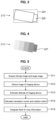
- FIG. 4 is a range image of the one imaging device imaged and outputted by the other according to the first embodiment of the present invention.
- FIG. 5 is a diagram illustrating a flowchart of a calibration processing according to the first embodiment of the present invention.
- FIG. 6 is a diagram for explaining how an imaging device is imaged according to a second embodiment.
- FIG. 7 is a diagram for explaining a bitmap image outputted by the imaging device according to the second embodiment.
- FIG. 8 is a diagram for explaining bitmap image outputted by another imaging device according to the second embodiment.
- FIG. 9 is a functional block diagram illustrating a calibration device according to the second embodiment.
- FIG. 10 is a diagram for explaining an attitude of the imaging device estimated by an attitude estimation part of a calibration device according to the second embodiment.
- FIG. 11 is a diagram for explaining a correction processing performed by a correction processing part according to the second embodiment.
- FIG. 12 is a flowchart of the calibration processing according to the second embodiment.
- FIG. 1 is a diagram illustrating an entire structure of a calibration system 10 according to a first embodiment of the present invention.
- the calibration system 10 includes a calibration device 100 and a pair of imaging devices 210 , 220 .
- Each of the imaging devices 210 , 220 is capable of measuring a distance between itself and a target to be imaged (a subject); and outputs a bitmap image (for example, a RGB image, see FIG. 3 to be described hereinafter) and a range image (see FIG. 4 to be described hereinafter) which is an image in which a pixel represents a distance, to the calibration device 100 .
- a bitmap image for example, a RGB image, see FIG. 3 to be described hereinafter
- a range image see FIG. 4 to be described hereinafter
- Each of the imaging devices 210 , 220 may have any circuit architecture, any type or position of a sensor installed therein, or the like, as long as each of the devices 210 , 220 is capable of measuring a distance.
- the devices 210 , 220 may be each a stereo camera with two CMOS (Complementary Metal Oxide Semiconductor) image sensors installed therein.
- the devices 210 , 220 may be each a device composed of a combination of a simple RGB camera and a ToF (Time-of-Flight) sensor using infrared laser combined with an image sensor, in which a relationship between respective pixel positions is appropriately adjusted.
- the devices 210 , 220 may be each a device using a structured light sensor composed of a combination of a projection pattern light emitting device and an image sensor.
- a pixel in a range image can be converted into a 3D coordinate by means of a coordinate transformation.
- a group of points represented by the transformed 3D coordinate is referred to as a point cloud.
- a bitmap image and a range image may be collectively referred to as a field-of-view image (or field-of-view information) hereinafter.
- the imaging devices 210 , 220 have 3D coordinate systems 211 , 221 , respectively.
- the coordinate systems 211 , 221 is each a right-handed coordinate system in which: a direction in which each of the imaging devices 210 , 220 takes an image is denoted as x-axis; and a downward direction with respect to each of the x-axes is denoted as z-axis.
- An image of the imaging device 220 is in a field of view of the imaging device 210 .
- a field-of-view image outputted by the imaging device 210 contains an image of the imaging device 220 .
- An origin of each of the coordinate systems 211 , 221 is, for example, a center of a lens disposed in a front end portion thereof. In order to provide an easy view, however, FIG. 1 illustrates the coordinate systems 211 , 221 with the lens centers thereof off the respective origins.
- a translation vector 230 is a position vector of the imaging device 220 viewed from the imaging device 210 .
- the calibration device 100 detects the imaging device 220 contained in a field-of-view image of the imaging device 210 .
- the calibration device 100 estimates a distance and a direction of the imaging device 220 (the translation vector 230 illustrated in FIG. 1 ) with respect to the imaging device 210 , based on a position and a distance of a point cloud of the imaging device 220 in a range image.
- the calibration device 100 computes a major component in a spread of the point cloud.
- the calibration device 100 thereby estimates an attitude (an orientation, that is, the coordinate system 221 ) of the imaging device 220 .
- a rotation matrix representing a rotation by which the coordinate system 221 is brought to a position parallel to the coordinate system 211 is calculated from the estimated result of the attitude of the imaging device 220 .
- the coordinate systems 211 , 221 can be transformed into each other, thus allowing respective field-of-view images of the imaging devices 210 , 220 to be integrated. Therefore, the translation vector 230 and the rotation matrix may be collectively referred to as transformation information. Note that calibration means computation of the transformation information.
- the translation vector 230 and the rotation matrix are calculated based on information on an image of the imaging device 220 contained in a field-of-view image of the imaging device 210 .
- the calculation can be done with a field of view of just one of the imaging devices 210 , 220 containing an image of the other.
- the calculation is performed using only information on pixels corresponding to an image of one of the imaging devices 210 , 220 contained in a field-of-view image of the other, which requires a small processing load. As a result, a high-speed calibration of an imaging device having a high flexibility to change positions thereof can be performed.
- FIG. 2 is a functional block diagram illustrating the calibration device 100 according to the first embodiment.
- the calibration device 100 includes a controller 110 , a storage part 120 , a communication part 130 , and an input and output part 140 .
- the communication part 130 allows an input of communication data including a field-of-view image from the imaging devices 210 , 220 .
- the communication part 130 transmits communication data including a field-of-view image, calculated transformation information, or an integrated field-of-view image using transformation information.
- the input and output part 140 is connected to a user interface device such as a display, a keyboard, and a mouse.
- the storage part 120 is realized by a ROM (Read Only Memory), a RAM (Random Access Memory), a SSD (Solid State Drive), or the like.
- the storage part 120 stores therein a global coordinate system 121 , a program 128 , and the like.
- the global coordinate system 121 is information on a coordinate system shared by the imaging devices 210 , 220 ; and includes information on a basis vector and an origin of the coordinate system.
- the coordinate system 211 of the imaging device 210 may serve as the global coordinate system 121 .
- the program 128 includes description of steps of a calibration processing to be explained later (see FIG. 5 to be described hereinafter).
- Controller Bitmap Image Acquisition Part and Range Image Acquisition Part>>
- the controller 110 is realized by a CPU (Central Processing Unit) and the like; and includes a bitmap image acquisition part 111 , a range image acquisition part 112 , a detection part 113 , an attitude estimation part 114 , a translation vector calculation part 115 , a rotation matrix calculation part 116 , and an image registration processing part 117 .
- the bitmap image acquisition part 111 acquires a bitmap image from a field-of-view image received from the imaging devices 210 , 220 .
- the range image acquisition part 112 acquires a range image from a field-of-view image received from the imaging devices 210 , 220 .
- FIG. 3 illustrates a bitmap image 212 of the imaging device 220 taken and outputted by the imaging device 210 according to the first embodiment.
- a subject 226 is an image of the imaging device 220 in the bitmap image 212 .
- FIG. 4 illustrates a range image 213 of the imaging device 220 taken and outputted by the imaging device 210 according to the first embodiment.
- a subject 227 is an image of the imaging device 220 in the range image 213 .
- the range image is an image in which information on range is added to each of pixels therein.
- a range is represented by luminance of a pixel.
- a right-hand portion thereof looks darker (lower in luminance), which means that a range in the right-hand portion is larger (farther away). Note that, though a background of the imaging device 220 is actually darker (lower in luminance) than the subject 227 , FIG. 4 skips illustrating the background to facilitate visualization.
- the detection part 113 detects an image of the imaging device 220 contained in the bitmap image acquired by the bitmap image acquisition part 111 , using an appropriate image processing.
- One of the simplest techniques of such a detection step is that a seal having a characteristic color or a high infrared reflectivity or any other characteristics is put on all or a desired part of the imaging device 220 , based on pixel values of which the imaging device 220 is detected and is subjected to segmentation.
- Another technique uses machine learning technology (for example, CNN (Convolutional Neural Network)) with images of an imaging device of interest as training data and performs an inference processing. A result of the detection may be presented in an area 225 (see FIG.
- a detection window for example, a rectangle
- a convex hull covering an entire image of a subject as a target for the detection or may be presented in an area in which pixels corresponding to an image of the imaging device 220 (the subject 226 ) are present.
- the attitude estimation part 114 estimates an attitude (an orientation, that is, the coordinate system 221 in FIG. 1 ) of the imaging device 220 with respect to the imaging device 210 , based on a result detected by the detection part 113 (see the area 225 in FIG. 3 ). using the range image acquired by the range image acquisition part 112 . How to estimate an attitude is described below.
- the attitude estimation part 114 identifies pixels of an image of the imaging device 220 contained in the range image, based on the detected result; and performs a coordinate transformation of the identified pixels, to thereby obtain a distribution of a point cloud corresponding to the imaging device 220 in the coordinate system 211 (see FIG. 1 ).
- the attitude estimation part 114 computes an attitude of the imaging device 220 from the distribution of the point cloud.
- the attitude estimation part 114 calculates a major component, based on the distribution of the point cloud; and thereby computes a coordinate axis of the coordinate system 221 .
- the attitude estimation part 114 computes a covariance matrix using a relative position vector of each of points in the point cloud having a position of a centroid of the distribution of the point cloud as an origin of the coordinate system 221 ; and thereby calculates an eigenvalue and an eigenvector of the computed covariance matrix.
- the attitude estimation part 114 then takes respective directions of eigenvectors corresponding to three large eigenvalues as coordinate axes.
- the respective coordinate axes are shown as basis vectors (each with a length of 1).
- the translation vector calculation part 115 calculates a position vector (the translation vector 230 illustrated in FIG. 1 ) from the imaging device 210 to the imaging device 220 , based on the result detected by the detection part 113 (see the area 225 in FIG. 3 ), using the range image acquired from the range image acquisition part 112 .
- the translation vector calculation part 115 acquires a point cloud of an image of the imaging device 220 in the coordinate system 211 ; and determines a position of a centroid of the point cloud as a translation vector.
- a rotation transformation (at a rotation transformation angle of about the x-axis of the coordinate system 211 and a rotation transformation (at a rotation transformation angle of n) about the y-axis thereof are performed in this order, such that a direction of the basis vector z in the coordinate system 221 be flush with a direction of the z-axis in the coordinate system 211 .
- each of x component and y component of the basis vector z takes a value of “0”, thus allowing the rotation transformation angles of and n to be calculated from Formula (1) and Formula (2), respectively.
- tan ⁇ ( ⁇ ) z y z z ( 1 )
- tan 2 ⁇ ( ⁇ ) z x 2 z y 2 + z z 2 ( 2 )
- the rotations described above make the basis vector x and the basis vector y positioned on the x-y plane in the coordinate system 211 of the imaging device 210 .
- a rotation transformation (at a rotation transformation angle is then performed about the z-axis of the coordinate system 211 , such that directions of the basis vector x and the basis vector y be flush with directions of the x-axis and the y-axis in the coordinate system 211 , respectively.
- y component of the basis vector x takes a value of “0”, thus allowing the rotation transformation angles to be calculated from Formula (3).
- a rotation matrix (a 3 ⁇ 3 matrix) of the rotation transformation angles ⁇ , ⁇ , and ⁇ obtained as described above in order of operations from the left, a rotation matrix can be calculated by which the x-y-z coordinate axes of the coordinate system 221 rotates to align with the x-y-z coordinate axes of the coordinate system 211 , respectively.
- the image registration processing part 117 integrates respective field-of-view images of the imaging devices 210 , 220 , based on the translation vector calculated by the translation vector calculation part 115 and the rotation matrix calculated by the rotation matrix calculation part 116 . That is, the image registration processing part 117 makes a pair of points—one contained in one of the two field-of-view images and another contained in the other—which are to be aligned by a coordinate transformation between the coordinate systems 211 , 221 using the translation vector and the rotation matrix (transformation information), correspond (registered) to each other.
- the image registration processing part 117 also makes appropriate adjustment to a basis vector and a position vector contained in the global coordinate system 121 (a coordinate transformation).
- an ICP (Iterative Closest Point) registration processing is performed.
- transformation information may be used as an initial value of the iterative computation processing. This can reduce the number of times of the iterative computation processings and also prevent initial value dependence.
- FIG. 5 is a flowchart illustrating a calibration processing according to the first embodiment.
- the calibration processing is performed at a prescribed time. For example, when the imaging devices 210 , 220 are installed in a mobile object such as a robot, the calibration processing is performed on a periodic basis. In another example in which the imaging device 210 is fixed, while the imaging device 220 is not fixed and is subjected to repeated movements or changes in attitude thereof, the calibration processing is performed after each of the movements or changes attitude of the imaging device 220 .
- step S 11 the bitmap image acquisition part 111 and the range image acquisition part 112 acquire a bitmap image and a range image, respectively, from a field-of-view image of each of the imaging devices 210 , 220 .
- step S 12 the detection part 113 : searches the bitmap image of each of the imaging devices 210 , 220 for whether or not the bitmap image of the imaging device 210 contains an image of the imaging device 220 and whether or not the bitmap image of the imaging device 220 contains an image of the imaging device 210 ; and acquires the detected image, if any. Description below is made assuming that the bitmap image of the imaging device 210 contains an image of the imaging device 220 .
- step S 13 the attitude estimation part 114 estimates an attitude of the imaging device 220 .
- step S 14 the translation vector calculation part 115 calculates a translation vector from the imaging device 210 to the imaging device 220 .
- the rotation matrix calculation part 116 also calculates a rotation matrix by which the coordinate system 221 of the imaging device 220 is aligned with the coordinate system 211 of the imaging device 210 .
- step S 15 the image registration processing part 117 integrates field-of-view information of each of the imaging devices 210 , 220 , using the translation vector and the rotation matrix (transformation information) calculated in step S 14 .
- the calibration device 100 detects an image of the imaging device 220 contained in the bitmap image of the imaging device 210 .
- the calibration device 100 calculates a translation vector from an image of the imaging device 220 contained in the range image of the imaging device 210 .
- the calibration device 100 acquires an attitude of the imaging device 220 from the image of the imaging device 220 contained in the range image; and thereby calculates such a rotation matrix that aligns the coordinate systems of the imaging devices 210 , 220 with each other.
- the calibration device 100 integrates the field-of-view information of each of the imaging devices 210 , 220 , using the translation vector and the rotation matrix (the transformation information).
- the calibration device 100 can calculate the transformation information as long as a field of view of one of a pair of imaging devices contains an image of the other. That is, it is not required that respective fields of view of the imaging devices contain each other's images, which reduces restrictions on relative positions or orientations of the imaging devices in conducting calibration therebetween. This increases flexibility to change installed positions or orientations of the imaging devices.
- transformation information When transformation information is acquired, information only on pixels of an image corresponding to an imaging device of interest in a field-of-view image of another imaging device is used in calculating a position or an attitude of the imaging device of interest, which requires a small processing load. A high-speed calibration can be thus performed. Additionally, a calibration processing can be repeatedly performed, which makes it possible to improve accuracy of transformation information, and, as a result, that of integration of field-of-view information.
- the attitude estimation part 114 calculates an attitude (coordinate axes and a basis vector) of an imaging device of interest, from a spread (a major component) of a point cloud of an image of the imaging device in a range image.
- an attitude of an imaging device of interest may be estimated from a bitmap image using machine learning technology. More specifically, an attitude of the imaging device may be estimated using a machine learning model which learns from training data in which a correct answer data of an attitude of the imaging device in a bitmap image is an actual attitude of the imaging device.
- an attitude of an imaging device is estimated from a field-of-view image.
- an imaging device has a high geometric symmetry (under a rotation or a mirror reflection) (for example, when the imaging device is cylindrical or rectangular)
- a calibration device can appropriately estimate an attitude of one of a pair of imaging devices and calculate transformation information, if a field of view of the one imaging device contains an image of the other, and at the same time, a field of view of the latter contains an image of the former.
- FIG. 6 is a diagram for explaining how a pair of imaging devices 240 , 250 take respective images according to the second embodiment.
- Each of the imaging devices 240 , 250 is mounted on an air vehicle (a drone); and has a 360-degree field of view.
- a translation vector 260 is a position vector of the imaging device 250 viewed from the imaging device 240 .
- the imaging devices 240 , 250 each have a cylindrical main body. It is thus difficult to distinguish by appearance between a front and a rear portion or between a right and a left portion (an attitude) of each of the imaging devices 240 , 250 , though an upper and a lower portion thereof may be correctly determined. More specifically, even when the attitude thereof is estimated based on a position of a propeller of the air vehicle, an error by n/2, n, or 3n/2 radians may be unavoidable.
- FIG. 7 is a diagram for explaining a bitmap image 245 outputted by the imaging device 240 according to the second embodiment.
- the ordinate and the abscissa in the bitmap image 245 correspond to a zenith angle and an azimuth angle of a coordinate system 241 of the imaging device 240 (see FIG. 6 ), respectively.
- a subject 256 is an image of the imaging device 250 in the bitmap image 245 .
- FIG. 8 is a diagram for explaining a bitmap image 255 outputted by the imaging device 250 according to the second embodiment.
- the ordinate and the abscissa in the bitmap image 255 correspond to a zenith angle and an azimuth angle of a coordinate system 251 of the imaging device 250 (see FIG. 6 ), respectively.
- a subject 246 is an image of the imaging device 240 in the bitmap image 255 .
- FIG. 9 is a functional block diagram illustrating a calibration device 100 A according to the second embodiment.
- the calibration device 100 A is the same as the calibration device 100 (see FIG. 2 ) according to the first embodiment, except that the calibration device 100 A further includes a correction processing part 118 in the controller 110 .
- the correction processing part 118 Prior to explanation of the correction processing part 118 , an error in estimating an attitude of the imaging device 250 is described next.
- FIG. 10 is a diagram for explaining an estimated result of an attitude of the imaging device 250 (see FIG. 6 ), which is estimated by the attitude estimation part 114 of the calibration device 100 A according to the second embodiment.
- the coordinate system 241 represents a coordinate system of the imaging device 240 .
- the x-y-z axes of the coordinate system 251 represent the x-y-z axes of a coordinate system of the imaging device 250 , respectively.
- the x′-y′-z axes of the coordinate system 251 is a coordinate system of the imaging device 250 calculated (estimated) by the attitude estimation part 114 .
- the attitude estimation part 114 correctly determines which direction is the z-axis of the imaging device 250 , that is, an upper and lower direction thereof, the attitude estimation part 114 incorrectly determines the x-y axes by ⁇ radians, failing to determine a front and rear direction and a left and right direction thereof. This inconveniently results in an incorrect calculation of a rotation matrix by the rotation matrix calculation part 116 .
- the correction processing part 118 corrects such an erroneously calculation result.
- FIG. 11 is a diagram for explaining a correction processing performed by the correction processing part 118 according to the second embodiment.
- An angular coordinate 270 is a 2D coordinate with the ordinate denoting an azimuth angle and the abscissas denoting a zenith angle.
- PBA be a translation vector from the imaging device 240 to the imaging device 250 calculated by the translation vector calculation part 115 .
- RBA be a rotation matrix calculated by the rotation matrix calculation part 116 .
- a point 273 denotes a zenith angle component and an azimuth angle component of ⁇ RBA ⁇ PBA. If the attitude estimation part 114 correctly estimates an attitude of the imaging device 250 , the calculated vector becomes equal to a translation vector from the imaging device 250 to the imaging device 240 .
- a point 271 denotes a zenith angle component and an azimuth angle component of a translation vector with respect to the imaging device 240 viewed from the imaging device 250 .
- a difference 272 represents a difference value ⁇ between the point 271 and a point 273 .
- the zenith angle component of the difference value ⁇ is zero, leaving only the azimuth angle component.
- an attitude of the imaging device 250 can be correctly estimated by rotating a basis vector of the coordinate system 251 of the imaging device 250 viewed from the imaging device 240 , by ⁇ about the z-axis of the coordinate system 251 .
- the correction processing part 118 calculates a rotation matrix T for an appropriate correction, using Rodrigues' rotation formula; and outputs the corrected rotation matrix as RBA ⁇ T ⁇ 1 (T ⁇ 1 is an inverse matrix of T).
- FIG. 12 is a flowchart illustrating a calibration processing according to the second embodiment.
- the calibration processing is performed at a prescribed time, for example, at regular intervals.
- step S 21 the bitmap image acquisition part 111 and the range image acquisition part 112 acquire a bitmap image and a range image, respectively, from each of respective field-of-view images of the imaging devices 240 , 250 .
- step S 22 the detection part 113 : searches the respective bitmap images of the imaging devices 240 , 250 for whether or not either of the bitmap images contain an image of the other's imaging device.
- step S 23 if either of the bitmap images containing an image of the other's imaging device is detected in step S 22 (step S 23 ⁇ YES), the detection part 113 advances the processing to step S 24 . If neither of the bitmap images containing an image of the other's imaging device is detected in step S 22 (step S 23 ⁇ NO), the detection part 113 terminates the calibration processing.
- step S 24 the attitude estimation part 114 estimates an attitude of the detected imaging device.
- step S 25 the translation vector calculation part 115 calculates a translation vector toward the detected imaging device.
- the rotation matrix calculation part 116 calculates a rotation matrix by which a coordinate system of the detected imaging device is aligned with a coordinate system of the other imaging device.
- steps S 24 and S 25 are performed to each of the imaging devices 240 , 250 .
- step S 26 if each of the imaging devices 240 , 250 is contained in each other's field of view (step S 26 ⁇ YES), the detection part 113 advances the processing to step S 27 . If each of the imaging devices 240 , 250 is not contained in each other's field of view (step S 26 ⁇ NO), the detection part 113 advances the processing to step S 29 .
- the terms “contained in a field of view” used herein means that one of the imaging devices detects, in a field-of-view thereof, an image of the other imaging device.
- step S 27 if a length of the difference value ⁇ (see FIG. 11 ) calculated from the translation vector and the rotation matrix is smaller than a prescribed value, meaning that an attitude of the imaging device of interest in the other's field of view is correctly estimated (step S 27 ⁇ Correct), the correction processing part 118 advances the processing to step S 29 . If the length of the difference value ⁇ is larger than the prescribed value (step S 27 ⁇ Incorrect), the correction processing part 118 advances the processing to step S 28 .
- step S 28 the correction processing part 118 calculates a rotation matrix T used for correction, based on the difference value ⁇ ; corrects the rotation matrix calculated in step S 25 ; and returns the processing to step S 27 .
- steps S 27 and S 28 may be performed to each of the imaging devices 240 , 250 or may be performed to either of the imaging devices 240 , 250 . Or, in place of using the difference value ⁇ , steps S 27 and S 28 may be repeated until a difference between the rotation matrix T used for correction and an identity matrix takes a value as small as a prescribed value.
- step S 29 the image registration processing part 117 integrates field-of-view information of the imaging device 240 and field-of-view information of the imaging device 250 .
- calibration can be appropriately performed, even when an imaging device of interest has a high geometric symmetry (under a rotation or a mirror reflection) (for example, and an attitude of the imaging device cannot be uniquely determined or is erroneously estimated. Additionally, when, for example, a pair of ranging devices performs estimation, the second embodiment can be used in double-checking a possible unexpected estimation result outputted by one of a pair of the ranging devices, which improves robustness.
- the number of units of the imaging device is two.
- the number may be, however, three or more.
- the calibration processing illustrated in FIG. 12 may be performed to a pair of any imaging devices.
- a single unit of the calibration device 100 / 100 A performs a calibration processing.
- a plurality of calibration devices may perform a calibration processing in a distributed manner.
- a plurality of imaging devices may each have the controller 110 (a CPU) and perform a calibration processing in parallel.
- An imaging device may perform part of a processing.
- each of imaging devices may: calculate transformation information; and transmit the calculated transformation information together with field-of-view information to a calibration device, at which the field-of-view information transmitted from each of the imaging devices is integrated.
Landscapes
- Engineering & Computer Science (AREA)
- Theoretical Computer Science (AREA)
- Multimedia (AREA)
- Physics & Mathematics (AREA)
- General Physics & Mathematics (AREA)
- Data Mining & Analysis (AREA)
- Signal Processing (AREA)
- Computer Vision & Pattern Recognition (AREA)
- General Engineering & Computer Science (AREA)
- Artificial Intelligence (AREA)
- Evolutionary Computation (AREA)
- Health & Medical Sciences (AREA)
- General Health & Medical Sciences (AREA)
- Databases & Information Systems (AREA)
- Evolutionary Biology (AREA)
- Bioinformatics & Computational Biology (AREA)
- Bioinformatics & Cheminformatics (AREA)
- Life Sciences & Earth Sciences (AREA)
- Remote Sensing (AREA)
- Vascular Medicine (AREA)
- Astronomy & Astrophysics (AREA)
- Medical Informatics (AREA)
- Software Systems (AREA)
- Computing Systems (AREA)
- Biomedical Technology (AREA)
- Studio Devices (AREA)
- Image Processing (AREA)
Abstract
Description
- [Patent Document 1] Japanese Laid-Open Patent Application, Publication No. 2007-327750
- [Patent Document 2] Japanese Laid-Open Patent Application, Publication No. 2005-233639
-
- 100, 100A calibration device
- 111 bitmap image acquisition part
- 112 range image acquisition part
- 113 detection part (state estimation part)
- 114 attitude estimation part (state estimation part)
- 115 translation vector calculation part (transformation information calculation part)
- 116 rotation matrix calculation part (transformation information calculation part)
- 117 image registration processing part (field-of-view integrate processing part)
- 118 correction processing part
- 210, 220, 240, 250 imaging device
- 211, 221, 241, 251 coordinate system
- 212 bitmap image
- 213 range image
- 230, 260 translation vector (relative position)
Claims (10)
Applications Claiming Priority (2)
| Application Number | Priority Date | Filing Date | Title |
|---|---|---|---|
| JP2020201534A JP7508350B2 (en) | 2020-12-04 | 2020-12-04 | CALIBRATION APPARATUS AND CALIBRATION METHOD |
| JP2020-201534 | 2020-12-04 |
Publications (2)
| Publication Number | Publication Date |
|---|---|
| US20220180086A1 US20220180086A1 (en) | 2022-06-09 |
| US11900669B2 true US11900669B2 (en) | 2024-02-13 |
Family
ID=81848190
Family Applications (1)
| Application Number | Title | Priority Date | Filing Date |
|---|---|---|---|
| US17/528,582 Active 2042-01-27 US11900669B2 (en) | 2020-12-04 | 2021-11-17 | Calibration device and calibration method |
Country Status (3)
| Country | Link |
|---|---|
| US (1) | US11900669B2 (en) |
| JP (1) | JP7508350B2 (en) |
| CN (1) | CN114615441B (en) |
Families Citing this family (9)
| Publication number | Priority date | Publication date | Assignee | Title |
|---|---|---|---|---|
| GB2599184B (en) | 2021-03-23 | 2022-11-23 | Imagination Tech Ltd | Intersection testing in a ray tracing system |
| GB2599186B (en) * | 2021-03-23 | 2022-10-12 | Imagination Tech Ltd | Intersection testing in a ray tracing system |
| GB2599181B8 (en) | 2021-03-23 | 2024-09-18 | Imagination Tech Ltd | Intersection testing in a ray tracing system |
| GB2599185B (en) * | 2021-03-23 | 2022-08-24 | Imagination Tech Ltd | Intersection testing in a ray tracing system |
| GB2599187B (en) | 2021-03-23 | 2022-09-21 | Imagination Tech Ltd | Intersection testing in a ray tracing system |
| CN114964316B (en) * | 2022-07-27 | 2022-11-01 | 湖南科天健光电技术有限公司 | Position and attitude calibration method and device, and method and system for measuring target to be measured |
| JP2024116738A (en) * | 2023-02-16 | 2024-08-28 | 株式会社ミツトヨ | Calibration method, measurement system, and program for a measurement device for measuring three-dimensional shapes |
| CN116572253B (en) * | 2023-06-29 | 2024-02-20 | 深圳技术大学 | A test tube grabbing control method and device |
| CN117922835B (en) * | 2024-03-22 | 2024-06-18 | 成都航空职业技术学院 | A loading device and a control method thereof |
Citations (13)
| Publication number | Priority date | Publication date | Assignee | Title |
|---|---|---|---|---|
| JP2005233639A (en) | 2004-02-17 | 2005-09-02 | Mitsubishi Electric Corp | Stereo camera system and calibration method between stereo cameras of the system |
| JP2007327750A (en) | 2006-06-06 | 2007-12-20 | National Institute Of Advanced Industrial & Technology | Camera position detection method |
| US20100172598A1 (en) * | 2007-07-12 | 2010-07-08 | Masayuki Kimura | Image processing device, image processing method, image processing program, recording medium with image processing program recorded therein, and image processing processor |
| US20160063704A1 (en) * | 2014-08-27 | 2016-03-03 | Kabushiki Kaisha Topcon | Image processing device, image processing method, and program therefor |
| US20170094256A1 (en) * | 2015-09-25 | 2017-03-30 | Intel Corporation | Single-view feature-less depth and texture calibration |
| US20180343421A1 (en) * | 2017-05-24 | 2018-11-29 | Trimble Inc. | Infrastructure positioning camera system |
| US20190156506A1 (en) * | 2017-08-07 | 2019-05-23 | Standard Cognition, Corp | Systems and methods to check-in shoppers in a cashier-less store |
| US20190304105A1 (en) * | 2018-04-03 | 2019-10-03 | Altumview Systems Inc. | High-performance visual object tracking for embedded vision systems |
| US20200089971A1 (en) * | 2018-09-19 | 2020-03-19 | Baidu Online Network Technology (Beijing) Co., Ltd. | Sensor calibration method and device, computer device, medium, and vehicle |
| US20200278197A1 (en) * | 2019-02-28 | 2020-09-03 | Canon Kabushiki Kaisha | Measurement apparatus, measurement method, system, storage medium, and information processing apparatus |
| US20200388004A1 (en) * | 2018-02-26 | 2020-12-10 | Intel Corporation | Method and system of point cloud registration for image processing |
| US20210051262A1 (en) * | 2018-08-29 | 2021-02-18 | SZ DJI Technology Co., Ltd. | Camera device and focus method |
| US20210152802A1 (en) * | 2017-08-08 | 2021-05-20 | Koninklijke Philips N.V. | Apparatus and method for generating a representation of a scene |
Family Cites Families (9)
| Publication number | Priority date | Publication date | Assignee | Title |
|---|---|---|---|---|
| US7212228B2 (en) * | 2002-01-16 | 2007-05-01 | Advanced Telecommunications Research Institute International | Automatic camera calibration method |
| JP4136859B2 (en) * | 2003-01-10 | 2008-08-20 | キヤノン株式会社 | Position and orientation measurement method |
| JP4533090B2 (en) * | 2004-05-14 | 2010-08-25 | キヤノン株式会社 | Index calibration apparatus and information processing method |
| JP6214867B2 (en) * | 2012-11-14 | 2017-10-18 | 株式会社東芝 | Measuring device, method and program |
| JP2015089590A (en) * | 2013-11-05 | 2015-05-11 | ファナック株式会社 | Method and apparatus for taking out bulked article by using robot |
| JP2016017913A (en) * | 2014-07-10 | 2016-02-01 | 国立大学法人鳥取大学 | Posture information preparation system, posture information preparation method, and posture information preparation program |
| JP6474179B2 (en) * | 2017-07-30 | 2019-02-27 | 国立大学法人 奈良先端科学技術大学院大学 | Learning data set creation method, and object recognition and position and orientation estimation method |
| JP6904843B2 (en) * | 2017-08-03 | 2021-07-21 | キヤノン株式会社 | Imaging device and its control method |
| JP2020035158A (en) * | 2018-08-29 | 2020-03-05 | アルパイン株式会社 | Attitude estimation device and calibration system |
-
2020
- 2020-12-04 JP JP2020201534A patent/JP7508350B2/en active Active
-
2021
- 2021-11-17 US US17/528,582 patent/US11900669B2/en active Active
- 2021-11-29 CN CN202111454360.5A patent/CN114615441B/en active Active
Patent Citations (13)
| Publication number | Priority date | Publication date | Assignee | Title |
|---|---|---|---|---|
| JP2005233639A (en) | 2004-02-17 | 2005-09-02 | Mitsubishi Electric Corp | Stereo camera system and calibration method between stereo cameras of the system |
| JP2007327750A (en) | 2006-06-06 | 2007-12-20 | National Institute Of Advanced Industrial & Technology | Camera position detection method |
| US20100172598A1 (en) * | 2007-07-12 | 2010-07-08 | Masayuki Kimura | Image processing device, image processing method, image processing program, recording medium with image processing program recorded therein, and image processing processor |
| US20160063704A1 (en) * | 2014-08-27 | 2016-03-03 | Kabushiki Kaisha Topcon | Image processing device, image processing method, and program therefor |
| US20170094256A1 (en) * | 2015-09-25 | 2017-03-30 | Intel Corporation | Single-view feature-less depth and texture calibration |
| US20180343421A1 (en) * | 2017-05-24 | 2018-11-29 | Trimble Inc. | Infrastructure positioning camera system |
| US20190156506A1 (en) * | 2017-08-07 | 2019-05-23 | Standard Cognition, Corp | Systems and methods to check-in shoppers in a cashier-less store |
| US20210152802A1 (en) * | 2017-08-08 | 2021-05-20 | Koninklijke Philips N.V. | Apparatus and method for generating a representation of a scene |
| US20200388004A1 (en) * | 2018-02-26 | 2020-12-10 | Intel Corporation | Method and system of point cloud registration for image processing |
| US20190304105A1 (en) * | 2018-04-03 | 2019-10-03 | Altumview Systems Inc. | High-performance visual object tracking for embedded vision systems |
| US20210051262A1 (en) * | 2018-08-29 | 2021-02-18 | SZ DJI Technology Co., Ltd. | Camera device and focus method |
| US20200089971A1 (en) * | 2018-09-19 | 2020-03-19 | Baidu Online Network Technology (Beijing) Co., Ltd. | Sensor calibration method and device, computer device, medium, and vehicle |
| US20200278197A1 (en) * | 2019-02-28 | 2020-09-03 | Canon Kabushiki Kaisha | Measurement apparatus, measurement method, system, storage medium, and information processing apparatus |
Also Published As
| Publication number | Publication date |
|---|---|
| CN114615441A (en) | 2022-06-10 |
| JP7508350B2 (en) | 2024-07-01 |
| CN114615441B (en) | 2024-07-12 |
| US20220180086A1 (en) | 2022-06-09 |
| JP2022089269A (en) | 2022-06-16 |
Similar Documents
| Publication | Publication Date | Title |
|---|---|---|
| US11900669B2 (en) | Calibration device and calibration method | |
| US11704869B2 (en) | System and method for determining geo-location(s) in images | |
| Jiao et al. | A novel dual-lidar calibration algorithm using planar surfaces | |
| Won et al. | Sweepnet: Wide-baseline omnidirectional depth estimation | |
| US11151741B2 (en) | System and method for obstacle avoidance | |
| Burschka et al. | V-GPS (SLAM): Vision-based inertial system for mobile robots | |
| US20160238394A1 (en) | Device for Estimating Position of Moving Body and Method for Estimating Position of Moving Body | |
| US12387356B2 (en) | Binocular vision-based environment sensing method and apparatus, and unmanned aerial vehicle | |
| CN116128966B (en) | A semantic localization method based on environmental objects | |
| US10740923B2 (en) | Face direction estimation device and face direction estimation method for estimating the direction of a face represented on an image | |
| KR102827978B1 (en) | 2D image and 3D point cloud registration method and system | |
| CN116929348A (en) | Factory AGV positioning method based on single base station UWB and visual inertia | |
| US20240114119A1 (en) | Image processing device, image processing method, and program | |
| Luong et al. | Consistent ICP for the registration of sparse and inhomogeneous point clouds | |
| JP4132068B2 (en) | Image processing apparatus, three-dimensional measuring apparatus, and program for image processing apparatus | |
| Mishra et al. | Localization of a smart infrastructure fisheye camera in a prior map for autonomous vehicles | |
| US20250078208A1 (en) | Image processing system, movable apparatus, image processing method, and storage medium | |
| Shibata et al. | Absolute scale structure from motion using a refractive plate | |
| Kawanishi et al. | Estimation of camera motion with feature flow model for 3D environment modeling by using omni-directional camera | |
| Kawanishi et al. | Construction of 3D environment model from an omni-directional image sequence | |
| Leishman et al. | Robust Motion Estimation with RBG-D Cameras | |
| Alouache et al. | An adapted block-matching method for optical flow estimation in catadioptric images | |
| Oh et al. | A camera center estimation based on perspective one point method | |
| Meguro et al. | Omni-directional Motion Stereo Vision based on Accurate GPS/INS Navigation System | |
| Goto et al. | 3D environment measurement using binocular stereo and motion stereo by mobile robot with omnidirectional stereo camera |
Legal Events
| Date | Code | Title | Description |
|---|---|---|---|
| AS | Assignment |
Owner name: HITACHI, LTD., JAPAN Free format text: ASSIGNMENT OF ASSIGNORS INTEREST;ASSIGNORS:MITANI, KEIICHI;TAJIMA, KAZUYUKI;YAMAZAKI, KAZUYOSHI;SIGNING DATES FROM 20211007 TO 20211012;REEL/FRAME:058140/0285 |
|
| FEPP | Fee payment procedure |
Free format text: ENTITY STATUS SET TO UNDISCOUNTED (ORIGINAL EVENT CODE: BIG.); ENTITY STATUS OF PATENT OWNER: LARGE ENTITY |
|
| STPP | Information on status: patent application and granting procedure in general |
Free format text: DOCKETED NEW CASE - READY FOR EXAMINATION |
|
| STPP | Information on status: patent application and granting procedure in general |
Free format text: NON FINAL ACTION MAILED |
|
| STPP | Information on status: patent application and granting procedure in general |
Free format text: RESPONSE TO NON-FINAL OFFICE ACTION ENTERED AND FORWARDED TO EXAMINER |
|
| STPP | Information on status: patent application and granting procedure in general |
Free format text: FINAL REJECTION MAILED |
|
| STPP | Information on status: patent application and granting procedure in general |
Free format text: DOCKETED NEW CASE - READY FOR EXAMINATION |
|
| STPP | Information on status: patent application and granting procedure in general |
Free format text: NOTICE OF ALLOWANCE MAILED -- APPLICATION RECEIVED IN OFFICE OF PUBLICATIONS |
|
| STPP | Information on status: patent application and granting procedure in general |
Free format text: PUBLICATIONS -- ISSUE FEE PAYMENT VERIFIED |
|
| STCF | Information on status: patent grant |
Free format text: PATENTED CASE |