US11897249B2 - Vibration generator and apparatus for engraving an image - Google Patents
Vibration generator and apparatus for engraving an image Download PDFInfo
- Publication number
- US11897249B2 US11897249B2 US17/243,174 US202117243174A US11897249B2 US 11897249 B2 US11897249 B2 US 11897249B2 US 202117243174 A US202117243174 A US 202117243174A US 11897249 B2 US11897249 B2 US 11897249B2
- Authority
- US
- United States
- Prior art keywords
- coil
- yoke
- springs
- movable piece
- stylus
- Prior art date
- Legal status (The legal status is an assumption and is not a legal conclusion. Google has not performed a legal analysis and makes no representation as to the accuracy of the status listed.)
- Active, expires
Links
- 230000010355 oscillation Effects 0.000 claims abstract description 19
- 230000001105 regulatory effect Effects 0.000 claims abstract description 7
- 241001422033 Thestylus Species 0.000 claims description 79
- 239000011347 resin Substances 0.000 claims description 19
- 229920005989 resin Polymers 0.000 claims description 19
- 230000002093 peripheral effect Effects 0.000 claims description 13
- 239000011248 coating agent Substances 0.000 claims description 8
- 238000000576 coating method Methods 0.000 claims description 8
- 238000010586 diagram Methods 0.000 description 16
- 238000006073 displacement reaction Methods 0.000 description 7
- 238000004804 winding Methods 0.000 description 4
- 238000005452 bending Methods 0.000 description 1
- 239000003086 colorant Substances 0.000 description 1
- 239000000463 material Substances 0.000 description 1
- 239000002184 metal Substances 0.000 description 1
Images


Classifications
-
- B—PERFORMING OPERATIONS; TRANSPORTING
- B06—GENERATING OR TRANSMITTING MECHANICAL VIBRATIONS IN GENERAL
- B06B—METHODS OR APPARATUS FOR GENERATING OR TRANSMITTING MECHANICAL VIBRATIONS OF INFRASONIC, SONIC, OR ULTRASONIC FREQUENCY, e.g. FOR PERFORMING MECHANICAL WORK IN GENERAL
- B06B1/00—Methods or apparatus for generating mechanical vibrations of infrasonic, sonic, or ultrasonic frequency
- B06B1/02—Methods or apparatus for generating mechanical vibrations of infrasonic, sonic, or ultrasonic frequency making use of electrical energy
- B06B1/04—Methods or apparatus for generating mechanical vibrations of infrasonic, sonic, or ultrasonic frequency making use of electrical energy operating with electromagnetism
- B06B1/045—Methods or apparatus for generating mechanical vibrations of infrasonic, sonic, or ultrasonic frequency making use of electrical energy operating with electromagnetism using vibrating magnet, armature or coil system
-
- B—PERFORMING OPERATIONS; TRANSPORTING
- B41—PRINTING; LINING MACHINES; TYPEWRITERS; STAMPS
- B41C—PROCESSES FOR THE MANUFACTURE OR REPRODUCTION OF PRINTING SURFACES
- B41C1/00—Forme preparation
- B41C1/02—Engraving; Heads therefor
-
- B—PERFORMING OPERATIONS; TRANSPORTING
- B42—BOOKBINDING; ALBUMS; FILES; SPECIAL PRINTED MATTER
- B42D—BOOKS; BOOK COVERS; LOOSE LEAVES; PRINTED MATTER CHARACTERISED BY IDENTIFICATION OR SECURITY FEATURES; PRINTED MATTER OF SPECIAL FORMAT OR STYLE NOT OTHERWISE PROVIDED FOR; DEVICES FOR USE THEREWITH AND NOT OTHERWISE PROVIDED FOR; MOVABLE-STRIP WRITING OR READING APPARATUS
- B42D25/00—Information-bearing cards or sheet-like structures characterised by identification or security features; Manufacture thereof
- B42D25/40—Manufacture
- B42D25/405—Marking
- B42D25/43—Marking by removal of material
- B42D25/44—Marking by removal of material using mechanical means, e.g. engraving
-
- B—PERFORMING OPERATIONS; TRANSPORTING
- B44—DECORATIVE ARTS
- B44B—MACHINES, APPARATUS OR TOOLS FOR ARTISTIC WORK, e.g. FOR SCULPTURING, GUILLOCHING, CARVING, BRANDING, INLAYING
- B44B1/00—Artist's machines or apparatus equipped with tools or work holders moving or able to be controlled three-dimensionally for making single sculptures or models
- B44B1/003—Artist's machines or apparatus equipped with tools or work holders moving or able to be controlled three-dimensionally for making single sculptures or models having several cutting tools
-
- B—PERFORMING OPERATIONS; TRANSPORTING
- B44—DECORATIVE ARTS
- B44B—MACHINES, APPARATUS OR TOOLS FOR ARTISTIC WORK, e.g. FOR SCULPTURING, GUILLOCHING, CARVING, BRANDING, INLAYING
- B44B1/00—Artist's machines or apparatus equipped with tools or work holders moving or able to be controlled three-dimensionally for making single sculptures or models
- B44B1/06—Accessories
-
- B—PERFORMING OPERATIONS; TRANSPORTING
- B44—DECORATIVE ARTS
- B44B—MACHINES, APPARATUS OR TOOLS FOR ARTISTIC WORK, e.g. FOR SCULPTURING, GUILLOCHING, CARVING, BRANDING, INLAYING
- B44B3/00—Artist's machines or apparatus equipped with tools or work holders moving or able to be controlled substantially two- dimensionally for carving, engraving, or guilloching shallow ornamenting or markings
- B44B3/005—Artist's machines or apparatus equipped with tools or work holders moving or able to be controlled substantially two- dimensionally for carving, engraving, or guilloching shallow ornamenting or markings characterised by the power drive
-
- B—PERFORMING OPERATIONS; TRANSPORTING
- B44—DECORATIVE ARTS
- B44B—MACHINES, APPARATUS OR TOOLS FOR ARTISTIC WORK, e.g. FOR SCULPTURING, GUILLOCHING, CARVING, BRANDING, INLAYING
- B44B3/00—Artist's machines or apparatus equipped with tools or work holders moving or able to be controlled substantially two- dimensionally for carving, engraving, or guilloching shallow ornamenting or markings
- B44B3/02—Artist's machines or apparatus equipped with tools or work holders moving or able to be controlled substantially two- dimensionally for carving, engraving, or guilloching shallow ornamenting or markings wherein plane surfaces are worked
-
- B—PERFORMING OPERATIONS; TRANSPORTING
- B44—DECORATIVE ARTS
- B44B—MACHINES, APPARATUS OR TOOLS FOR ARTISTIC WORK, e.g. FOR SCULPTURING, GUILLOCHING, CARVING, BRANDING, INLAYING
- B44B3/00—Artist's machines or apparatus equipped with tools or work holders moving or able to be controlled substantially two- dimensionally for carving, engraving, or guilloching shallow ornamenting or markings
- B44B3/06—Accessories, e.g. tool or work holders
- B44B3/063—Tool holders
-
- H—ELECTRICITY
- H02—GENERATION; CONVERSION OR DISTRIBUTION OF ELECTRIC POWER
- H02K—DYNAMO-ELECTRIC MACHINES
- H02K33/00—Motors with reciprocating, oscillating or vibrating magnet, armature or coil system
-
- H—ELECTRICITY
- H02—GENERATION; CONVERSION OR DISTRIBUTION OF ELECTRIC POWER
- H02K—DYNAMO-ELECTRIC MACHINES
- H02K33/00—Motors with reciprocating, oscillating or vibrating magnet, armature or coil system
- H02K33/18—Motors with reciprocating, oscillating or vibrating magnet, armature or coil system with coil systems moving upon intermittent or reversed energisation thereof by interaction with a fixed field system, e.g. permanent magnets
-
- H—ELECTRICITY
- H02—GENERATION; CONVERSION OR DISTRIBUTION OF ELECTRIC POWER
- H02K—DYNAMO-ELECTRIC MACHINES
- H02K35/00—Generators with reciprocating, oscillating or vibrating coil system, magnet, armature or other part of the magnetic circuit
- H02K35/06—Generators with reciprocating, oscillating or vibrating coil system, magnet, armature or other part of the magnetic circuit with moving flux distributors, and both coil systems and magnets stationary
Definitions
- the present invention relates to a vibration generator to output fine vibration and an apparatus for engraving an image on a medium to be engraved using the vibration generator.
- the apparatus vibrates a stylus based on an image signal which is an electric signal converted from image data and performs fine engraving with the vibrating stylus. This forms an image corresponding to a photograph, an illustration or the like on the medium to be engraved.
- the apparatus for engraving an image has an electromagnet and a permanent magnet as a vibration generator.
- the permanent magnet is attached to a base and a movable piece of the electromagnet is vibrated relatively to the permanent magnet to apply the vibration to the stylus. Namely, current is applied to a coil supported with the movable piece in both forward and backward directions to switch magnetic poles of the movable piece. With this, the movable piece on the electromagnet is vibrated relatively to the permanent magnet.
- the coil is, however, vibrated as well as the movable piece.
- the apparatus is, therefore, limited on adapting to fine vibration and is limited on precisely fine engraving and the like.
- An object of the present invention is to provide a vibration generator and an apparatus for engraving an image using the vibration generator, capable of accurately adapting to fine vibration.
- a first aspect of the present invention provides a vibration generator, having a stationary permanent magnet, a yoke for the permanent magnet, a coil fixed to the yoke, four springs provided to the yoke, and a movable piece supported with the yoke through the four springs and configured to vibrate relatively to the yoke according to current applied to the coil in a forward and a backward directions.
- the yoke has a pair of yoke bodies with first ends and second ends, a coil fixing portion and four spring supports for the respective four springs, the first ends connected to respective south and north poles of the permanent magnet, the second ends having symmetric two pairs of projections facing each other to form a pair of south and north poles in each pair of the projections, the coil fixing portion into which the coil is accommodated and fixed in the middle between the two pairs of the projections, and springs of the four spring supports, on each side of the coil fixing portion, are symmetrically arranged between the coil fixing portion and a corresponding one of the two pairs of the projections to support respective corresponding springs of the four springs.
- the movable piece has a central portion, end portions and an arm, the end portions symmetrically projecting from the central portion and arranged between the respective two pairs of the projections with first gaps, the central portion arranged in the coil fixing portion, and the arm projecting from one of the end portions to output vibration.
- the springs have a teardrop sectional shape with a pointed end on a first side and an arc-shaped portion on a second side, the pointed ends of the springs supported with the respective spring supports, and the arc-shaped portions of the springs supporting the movable piece on both sides of the central portion.
- the coil in the coil fixing portion having an outer periphery and an inner periphery, the outer periphery fixed to the yoke through resin, the inner periphery having a through-hole in which the central portion of the movable piece is arranged with second gaps, the second gaps having a size to allow oscillation, which is regulated by the first gaps, of the central portion of the movable piece so that the central portion of the movable piece is oscillated and vibrated with the second gaps when the end portions of the movable piece are vibrated with the first gaps according to the current applied to the coil in the forward and the backward directions, thereby to vibrate the movable piece in seesaw operation.
- a second aspect of the present invention provides an apparatus for engraving an image having the vibration generator.
- the apparatus for engraving an image has a stylus to engrave an image, a stylus holder connected to the arm of the vibration generator and holding the stylus, a support spring supporting the stylus holder to allow the stylus holder to be vibrated according to resiliency of the support spring, a table configured to support a medium to be engraved and move in an X-axis direction, a Y-axis direction, and a Z-axis direction relatively to the stylus according to an engraving signal, and a controller configured to control application of the current and relative movement of the table and the stylus.
- the vibration generator is set to output the vibration from the arm to vibrate the stylus holder in the Z-axis direction.
- the support spring is arranged so as to be extended from a base end to a front end in a lateral direction, the base end fixed to a fixing portion and the front end at which the stylus holder is supported.
- the controller applies the current to the coil in the forward and the backward directions according to the engraving signal to vibrate the stylus in the Z-axis direction and causes the relative movement of the table and the vibrating stylus to move the vibrating stylus relatively to the medium supported on the table in the X-axis direction, the Y-axis direction, and the Z-axis direction, thereby to engrave an image on the medium to be engraved.
- the central portion of the movable piece is allowed to be oscillated and vibrated with the second gaps when the end portions of the movable piece are naturally vibrated with the first gaps according to the current applied in the forward and the backward directions. This allows the movable piece to be more finely vibrated.
- an image is engraved on the medium according to the relative movement of the stylus and the table in the X-axis direction, the Y-axis direction and the Z-axis direction, the stylus vibrating in the Z-axis direction.
- FIG. 1 is a perspective view partly illustrating an apparatus for engraving an image according to a first embodiment of the present invention
- FIG. 2 is a perspective view illustrating a vibration generator and a stylus of the apparatus
- FIG. 3 is a perspective view illustrating the vibration generator
- FIG. 4 is a side view of the vibration generator
- FIG. 5 is a front view of the vibration generator
- FIG. 6 is a front view of a yoke with an electromagnet of the vibration generator
- FIG. 7 is a perspective view illustrating a stack of yoke plates of the yoke
- FIG. 8 is a perspective view illustrating a yoke plate
- FIG. 9 is a perspective view illustrating a stack of piece-plates of a movable piece of the vibration generator.
- FIG. 10 is a perspective view illustrating a piece-plate
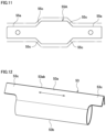
- FIG. 11 is a front view illustrating the piece-plate
- FIG. 12 is a perspective view illustrating a teardrop spring of the vibration generator
- FIG. 13 is a sectional view illustrating the teardrop spring
- FIG. 14 is a perspective view illustrating a coil of the electromagnet
- FIG. 15 is a conceptual diagram illustrating an apparatus for engraving an image having double vibration generators according to a second embodiment of the present invention.
- FIG. 16 A is a schematic diagram illustrating resolution of an engraved image formed by the apparatus with the single vibration generator of the first embodiment
- FIG. 16 B is a schematic diagram illustrating resolution of an engraved image formed by the apparatus with the double vibration generators of the second embodiment
- FIG. 17 A is a schematic diagram illustrating an engraved image formed by the apparatus with the single vibration generator of the first embodiment
- FIG. 17 B is a schematic diagram illustrating an engraved image formed by the apparatus with the double vibration generators of the second embodiment
- FIG. 18 is a table illustrating assignment of signals of an adder circuit and a subtraction circuit
- FIG. 19 A is a table for explaining signal diagrams in FIG. 18 ;
- FIG. 19 B is a table for explaining engraved diagrams corresponding to the signal diagrams in FIG. 18 .
- Each of the embodiments provides a vibration generator and an apparatus for engraving an image using the vibration generator, capable of accurately adapting to fine vibration.
- the vibration generator has a stationary permanent magnet, a yoke for the permanent magnet, a coil fixed to the yoke, four springs provided to the yoke, and a movable piece supported with the yoke through the four springs.
- the movable piece is configured to vibrate relatively to the yoke according to current applied to the coil in a forward and a backward directions.
- the yoke has a pair of yoke bodies with first ends and second ends, a coil fixing portion and four spring supports for the respective four springs.
- the first ends are connected to respective south and north poles of the permanent magnet.
- the second ends have symmetric two pairs of projections facing each other to form a pair of south and north poles in each pair of the projections.
- the coil fixing portion accommodates and fixes the coil in the middle between the two pairs of the projections.
- the springs of the four spring supports, on each side of the coil fixing portion are symmetrically arranged between the coil fixing portion and a corresponding one of the two pairs of the projections to support respective corresponding springs of the four springs.
- the movable piece has a central portion, end portions and an arm.
- the end portions symmetrically project from the central portion and are arranged between the respective two pairs of the projections with first gaps.
- the central portion is arranged in the coil fixing portion.
- the arm projects from one of the end portions to output vibration.
- the springs have a teardrop sectional shape with a pointed end on a first side and an arc-shaped portion on a second side.
- the pointed ends of the springs are supported with the respective spring supports, and the arc-shaped portions of the springs support the movable piece on both sides of the central portion.
- the coil in the coil fixing portion has an outer periphery and an inner periphery.
- the outer periphery is fixed to the yoke through resin
- the inner periphery has a through-hole in which the central portion of the movable piece is arranged with second gaps.
- the second gaps have a size to allow oscillation, which is regulated by the first gaps, of the central portion of the movable piece.
- the spring supports are provided on at least four positions so as to be symmetrically arranged.
- the number of the spring supports may be increased.
- the number of the springs my be increased according to the number of the spring supports.
- the outer periphery of the coil should be a portion other than the through-hole of the coil and includes an outermost periphery, a peripheral side face and the like.
- the size of the second gaps should be set so as to allow the oscillation of the central portion of the movable piece when the end portions of the movable piece vibrate with the first gaps.
- the second gaps may have a minimum size or more unless the second gaps restrict the oscillation.
- the second gaps never become zero at least before the end portions of the movable piece come into contact with the projections of the yoke to make the corresponding respective first gaps become zero.
- the first and the second gaps may become zero simultaneously.
- the vibration generator may have a resin coating forming the inner periphery of the coil to define the through-hole.
- the resin coating has a planar inner peripheral face and rounded or chamfered edges adjoining to the inner peripheral face to define openings of the through-hole.
- the rounded or chamfered edges face the arc-shaped portions of the springs.
- a rounded shape or chamfered shape of the rounded or chamfered edges should allow the arc-shaped portions of the springs to deform within a limited space.
- the vibration generator may have a pair of brackets and openings of the pair of brackets.
- the pair of brackets hold the permanent magnet and the yoke are held therebetween.
- the openings are formed on the pair of the brackets to face the coil fixing portion.
- the coil has side portions projected out from the respective openings of the brackets and is fixed on outer faces of the respective brackets through resin.
- An apparatus for engraving an image having the vibration generator has a stylus, a stylus holder, a support spring, a table and a controller.
- the stylus is to engrave an image.
- the stylus holder is connected to the arm of the vibration generator and holds the stylus.
- the support spring supports the stylus holder to allow the stylus holder to be vibrated according to resiliency of the support spring.
- the table is configured to support a medium to be engraved and move in an X-axis direction, a Y-axis direction, and a Z-axis direction relatively to the stylus according to an engraving signal.
- the controller is configured to control application of the current and relative movement of the table and the stylus.
- the vibration generator is set to output the vibration from the arm to vibrate the stylus holder in the Z-axis direction.
- the support spring is arranged so as to be extended from a base end to a front end in a lateral direction, the base end fixed to a fixing portion and the front end at which the stylus holder is supported.
- the controller conducts to apply the current to the coil in the forward and the backward directions according to the engraving signal to vibrate the vibrating stylus in the Z-axis direction and causes the relative movement of the table and the vibrating stylus to move the stylus relatively to the medium supported on the table in the X-axis direction, the Y-axis direction, and the Z-axis direction, thereby to engrave an image on the medium to be engraved.
- the support spring may have various shapes as long as the support spring allows the stylus holder to vibrate in the Z-axis direction.
- a structure for the relative movement of the stylus and the table is optional. Namely, an X-axis, a Y-axis and a Z-axis drivers are employed to move any one or both of the table and the stylus. There are various combinations to move the table and the stylus with the drivers.
- the table may be driven by the X-axis driver and the vibration generator may be driven by the Y-axis and the Z-axis drivers to move the stylus in the Y-axis and the Z-axis directions.
- the table may be driven by the Y-axis driver and the vibration generator may be driven by the X-axis and the Z-axis drivers.
- the table may be driven by the Z-axis driver and the vibration generator may be driven by the X-axis and the Y-axis drivers.
- the apparatus may have an additional vibration generator having the same configuration as the above-mentioned vibration generator.
- the additional vibration generator is set to output vibration in the X-axis direction.
- the stylus holder is connected to the arm of the additional vibration generator as well as the arm of the vibration generator.
- the resiliency of the support spring is set to allow the stylus holder to vibrate in the X-axis and the Z-axis directions.
- the controller conducts to apply the current to the respective coils of the vibration generators in the forward and the backward directions according to the engraving signal to vibrate the stylus in the X-axis and the Z-axis directions and causes the relative movement of the table and the stylus to move the stylus relatively to the medium supported on the table in the X-axis direction, the Y-axis direction, and the Z-axis direction, thereby to engrave an image on the medium to be engraved.
- FIG. 1 is a perspective view partly illustrating an apparatus for engraving an image according to the first embodiment of the present invention.
- FIG. 2 is a perspective view illustrating a vibration generator and a stylus of the apparatus.
- an apparatus 1 for engraving an image has a main body (not illustrated) storing a controller and the like.
- the apparatus 1 is provided with an X-axis table 5 , a Y-axis table 7 and a Z-axis drive mechanism 9 and the like on the main body.
- the X-axis table 5 serves as a table configured to support a medium to be engraved. According to the embodiment, the medium is put and fixed on the X-axis table 5 .
- the X-axis table 5 is reciprocatingly movable in an X-axis direction in a horizontally extending X-Y plane.
- the Y-axis table 7 is reciprocatingly movable to move an engraving head 11 in a Y-axis direction in the X-Y plane.
- the Y-axis direction is orthogonal to the X-axis direction.
- the Z-axis drive mechanism 9 vertically drives the engraving head 11 .
- the engraving head 11 includes a stylus 13 and vibrates the stylus 13 according to an input engraving signal.
- the engraving head 11 moves the stylus 13 relatively to the medium supported on the X-axis table 5 in the X-axis direction, the Y-axis direction, and the Z-axis direction according to relative movement of the X-axis table 5 and the stylus 13 based on the engraving signal, thereby to engrave an image on the medium to be engraved with the stylus 13 .
- the engraving signal is an analogue signal converted from a digital signal of an image read from a picture or the like.
- the engraving head 11 is vertically movable by a stepping motor system, a belt drive system, a ball screw system or other driving systems included in the Z-axis drive mechanism 9 as a Z-axis driver arranged behind the engraving head 11 . Further, the engraving head 11 is movable in a forward and backward direction as the Y-axis direction by the Y-axis table 7 driven by a Y-axis driver 15 arranged under the Z-axis drive mechanism 9 .
- the Y-axis direction is a row direction in scanning of the medium to be engraved.
- the X-axis table 5 is driven by an X-axis driver 16 and is movable in a right and left direction as the X-axis direction.
- the X-axis direction is a column direction in the scanning of the medium to be engraved.
- a medium to be engraved such as passport and card is put and fixed.
- the stylus 13 of the engraving head 11 and the X-axis table 5 on which the medium is supported perform the relative movement in the X-axis direction, the Y-axis direction, and the Z-axis direction.
- the apparatus 1 is set to output the vibration from the engraving head 11 in the Z-axis direction.
- the engraving head 11 is provided with a vibration generator 19 .
- the vibration generator 19 includes arms 21 through which the vibration is output.
- a support block 22 is attached to front ends of the arms 21 .
- a stylus holder 25 is connected to the support block 22 through a connecting member 23 in the Z-axis direction.
- the connecting member 23 is a wire having rigidity to transmit the vibration in the Z-axis direction.
- the connecting member 23 is made of, for example, metal and elongated in the Z-axis direction.
- the stylus holder 25 therefore, is connected to the arms 21 through the connecting member 23 in the Z-axis direction.
- the stylus holder 25 is supported at front ends of upper and lower support springs 27 a and 27 b which allow the stylus holder 25 to be vibrated in the Z-axis direction according to resiliency of the support springs 27 a and 27 b .
- Each of the support springs 27 a and 27 b is a plate spring and has a pair of parallel legs arranged apart from each other in the X-axis direction.
- the support springs 27 a and 27 b have base ends fixed to a fixing block 29 which is a fixing portion. Namely, the support springs 27 a and 27 b are arranged so as to be extended from the base end on the fixing block 29 to the front end on the stylus holder 25 in a lateral direction.
- the stylus holder 25 supports the stylus 13 .
- the vibration generator 19 has one side fixed to a float plate 33 through a plate spring member 31 and the other side connected to a joint plate 35 .
- the joint plate 35 is connected to an adjustment screw 37 for the stylus 13 .
- the adjustment screw 37 is screwed to the float plate 33 and is rotationally operable by a knob 39 with a scale.
- the float plate 33 is joined to a frame 43 of the engraving head 11 through a plate spring 41 .
- the fixing block 29 is also fixed to the float plate 33 .
- the stylus 13 therefore, vibrates in the Z-axis direction in conjunction with vibration due to seesaw operation of a movable piece 55 according to current applied to a coil 51 in a forward and a backward directions based on an engraving signal.
- the vibrating stylus 13 engraves an image on the medium to be engraved according to the relative movement of the X-axis table 5 and the stylus 13 in the X-axis direction, the Y-axis direction, and the Z-axis direction based on the engraving signal.
- FIGS. 3 - 5 are a perspective view, a side view and a front view each illustrating the vibration generator 19 .
- FIG. 6 is a front view of a yoke 49 with an electromagnet 50 of the vibration generator 19 .
- FIG. 7 is a perspective view illustrating a stack of yoke plates 49 A of the yoke 49 .
- FIG. 8 is a perspective view illustrating a yoke plate 49 a .
- FIG. 9 is a perspective view illustrating a stack of piece-plates 55 A of the movable piece 55 of the vibration generator 19 .
- FIG. 10 is a perspective view illustrating a piece-plate 55 A.
- FIG. 11 is a front view illustrating the piece-plate 55 A.
- FIG. 12 is a perspective view illustrating a teardrop spring 53 of the vibration generator 19 .
- FIG. 13 is a sectional view illustrating the teardrop spring 53 .
- FIG. 14 is a perspective view illustrating the coil 51 of
- the vibration generator 19 includes a stationary permanent magnet 47 , the yoke 49 , the coil 51 and the movable piece 55 .
- the movable piece 55 is supported with the yoke 49 through the four springs 53 and is configured to vibrate relatively to the yoke 49 according to the current applied to the coil 51 in the forward and backward directions.
- the permanent magnet 47 , the yoke 49 and the coil 51 form a stationary side and the movable piece 55 forms a movable side which is movable to vibrate relatively to the stationary side.
- the permanent magnet 47 includes, for example, three blocks 47 a having a rectangular parallelepiped shape and vertically stacked one on another in series.
- the blocks of the permanent magnet may be arranged in parallel to be connected to the yoke 49 .
- the yoke 49 includes a pair of yoke upper and lower bodies 49 a and 49 b .
- the pair of the yoke upper and lower bodies 49 a and 49 b have stacked structures of yoke plates 49 A, respectively.
- the pair of the yoke upper and lower bodies 49 a and 49 b form therebetween a magnet attaching portion 49 c on a first side and form therebetween a piece arranging portion 49 d and a coil fixing portion 49 e on a second side.
- the magnet attaching portion 49 c is formed into a rectangular shape opened to outside on one side.
- the magnet attaching portion 49 c is defined by an upper part and a lower part.
- the upper part of the magnet attaching portion 49 c is formed by a first end 49 f of the yoke upper body 49 a and the lower part of the magnet attaching portion 49 c is formed by a first end 49 g of the yoke lower body 49 b .
- the first end 49 f of the yoke upper body 49 a is connected to an upper pole, for example a north pole, of the permanent magnet 47 arranged in the magnet attaching portion 49 c .
- the first end 49 g of the yoke lower body 49 b is connected to a lower pole, for example south pole, of the permanent magnet 47 .
- the first ends 49 f and 49 g of the yoke upper and lower bodies 49 a and 49 b are connected to the respective north and the south poles of the permanent magnet 47 .
- the piece arranging portion 49 d is formed between second ends of the yoke upper and lower bodies 49 a and 49 b .
- the piece arranging portion 49 d is defined by an upper part and a lower part.
- a pair of projections 49 h and 49 i face each other and are respectively provided on the upper and the lower parts of the piece arranging portion 49 d .
- a pair of projections 49 j and 49 k face each other and are respectively provided on the upper and the lower parts of the piece arranging portion 49 d .
- the pair of the projections 49 h and 49 i is paired with the pair of the projections 49 j and 49 k in the Y-axis direction.
- the number of the pairs of the projections is not limited to two and may be four or more so as to put the pairs symmetrically.
- the second ends of the yoke upper and lower bodies 49 a and 49 b which are the pair of the yoke bodies have symmetric two pairs of the projections 49 h , 49 i , 49 j and 49 k facing each other so as to form a pair of south and north poles in each pair of the projections 49 h , 49 i , 49 j and 49 k .
- the projections 49 h and 49 j of the yoke upper body 49 a are north poles
- the projections 49 i and 49 k of the yoke lower body 49 b are south poles.
- the yoke 49 has the coil fixing portion 49 e in which the coil 51 is accommodated and fixed in the middle between the two pairs of the projections 49 h , 49 i , 49 j and 49 k .
- the coil fixing portion 49 e is a hole formed into a vertically and bilaterally symmetrical shape and passes through the yoke 49 in the X-axis direction.
- the coil fixing portion 49 e includes cutouts 49 ea and 49 eb .
- the cutout 49 ea is formed downward on the second side of the yoke upper body 49 a and the cutout 49 eb is formed upward on the second side of the yoke lower body 49 b .
- the cutouts 49 ea and 49 eb are respectively located on both sides of the piece arranging portion 49 d in the vertical direction.
- the yoke 49 has spring supports 57 at at least four positions so as to be symmetrically arranged according to the projections 49 h , 49 i , 49 j and 49 k .
- the spring supports 57 support the springs 53 on both sides of the coil fixing portion 49 e in the Y-axis direction between the respective pairs of the projections 49 h , 49 i , 49 j and 49 k .
- the four spring supports 57 are formed into the same shape.
- the upper two spring supports 57 are inclined so as to be oriented toward a lower inside of the downward cutout 49 ea .
- the lower two spring supports 57 are inclined so as to be oriented toward an upper inside of the upward cutout 49 eb .
- Each spring support 57 is a cutout formed to have a triangular shape between a corresponding one of the projections 49 h , 49 i , 49 j and 49 k and the coil fixing portion 49 e .
- the shape of the spring support 57 corresponds to a pointed end of the spring 53 (explained later).
- the spring support 57 is configured to tightly receive and support the pointed end of the spring 53 so as to be tightly fitted.
- the permanent magnet 47 and the yoke 49 are held between a pair of brackets 59 and the brackets 59 are fastened by a bolt 61 and a nut 62 .
- the pair of the brackets 59 have openings 59 a to correspond to the coil fixing portion 49 e .
- the openings 59 a open the coil fixing portion 49 e to the outside of the brackets 59 .
- the brackets 59 have fastening portion 59 b fastened to the float plate 33 of the engraving heat 11 being the stationary side.
- the movable piece 55 is a stack of piece-plates 55 A as illustrated in FIGS. 3 - 5 and 9 - 11 .
- the stack as the movable piece 55 integrally has the arms 21 at a center on one end of the movable piece 55 in the Y-axis direction.
- the arms 21 locally or partly project from the movable piece 55 .
- the arms 21 integrally project from the two piece-plates 55 A in the center in the X-axis direction to output vibration.
- the movable piece 55 has end portions 55 a and a central portion 55 b .
- the end portions 55 a symmetrically laterally project from the both sides of the central portion 55 b in the Y-axis direction.
- the end portions 55 a of the movable piece 55 are arranged with first gaps t 1 between the respective pairs of the projections 49 h , 49 i , 49 j and 49 k .
- the central portion 55 b is expanded upward and downward with respect to the end portions 55 a .
- the central portion 55 b is located between the downward and upward cutouts 49 ea and 49 eb of the coil fixing portion 49 e .
- the movable piece 55 also includes spring receiving portions 55 c between the central portion 55 b and the respective end portions 55 a .
- the spring receiving portions 55 c are inclined steps between the central portion 55 b and the respective end portions 55 a .
- the spring receiving portions 55 c support arc-shaped portions of the springs 53 , respectively.
- At least four springs 53 are provided according to the spring supports 57 .
- the number of the springs 53 may be increased as well as the number of the spring supports 57 .
- the springs 53 are formed by bending plate springs, so that each of the springs 53 has a symmetrical teardrop sectional shape.
- the spring 53 has the pointed end 53 a on the first side and the arc-shaped portion 53 b on the second side.
- the pointed end 53 a is a butted portion at which the ends of the bent plate spring forming the spring 53 are butted to each other.
- the arc-shaped portion 53 b has a curvature radius r and the ends of the bent plate spring project from an imaginary circle with the curvature radius r along tangential lines to form the pointed end 53 a .
- a minimum distance between an apex 53 ab of the pointed end 53 and the imaginary circle of the curvature radius r is smaller than the curvature radius r.
- the pointed end 53 a has a shape to be tightly fitted to the spring support 57 . Both side faces of the pointed end 53 a are brought into contact and supported with inner faces of the spring support 57 .
- the arc-shaped portion 53 b has the curvature to support the spring receiving portion 55 c of the movable piece 55 .
- the spring 53 is interposed between the spring support 57 and the spring receiving portion 55 c to have a line of symmetry inclined.
- the spring 53 has side portions 53 c of the pointed end 53 a longitudinally projecting with respect to the arc-shaped portion 53 b .
- the arc-shaped portion 53 b is, therefore, accurately brought into contact with the spring receiving portion 55 c while the pointed end 53 a is accurately supported with the spring support 57 .
- the coil 51 is wound in a rectangular shape.
- the winding shape is optional and the coil 51 may be wound so as to have an oval outer periphery or the like.
- a winding direction of the coil 51 is a direction orthogonal to an arranging direction along which the movable piece 55 is arranged.
- the up, down, right and left of the coil 51 are in the Z-axis and the X-axis directions.
- the coil 51 has a through-hole 51 a inside the rectangular shape, the through-hole 51 a in which the central portion 55 b of the movable piece 55 is arranged.
- the through-hole 51 a of the coil 51 has a precise flat plane at an inner periphery by winding a wire of the coil 51 .
- the coil 51 is entirely coated with resin in this embodiment.
- the resin coating 52 of the coil 51 forms the inner periphery of the coil 51 to define the through-hole 51 a .
- the resin coating 52 has a planar inner peripheral face 51 aa and rounded or chamfered edges Slab.
- the rounded or chamfered edges Slab are adjoining to the inner peripheral face 51 aa to define openings of the through-hole 51 a and face the arc-shaped portions 53 b of the springs 53 . This allows interspaces between the coil 51 and the respective springs 53 to be made narrow.
- the shapes of the inner peripheral face 51 aa and the rounded or chamfered edges Slab of the through hole 51 a accurately define an oscillation range of the central portion 55 b of the movable piece 55 and enable the arc-shaped portions 53 b of the springs 53 to be accurately operated. Accordingly, second gaps t 2 are formed between the central portion 55 b of the movable piece 55 and the inner peripheral face 51 aa of the through-hole 51 a of the coil 51 so as to be minimized according to the size of the first gaps t 1 . At the same time, the coil 51 and the springs 53 are close to each other. The vibration generator 19 as a whole is, therefore, reduced in size.
- a temperature sensor 51 c is attached to the coil 51 to detect coil temperature during the operation.
- a signal of the detected temperature is input to the controller to control the temperature of the coil 51 during the operation.
- the coil 51 is accommodated in the coil fixing portion 49 e and is fixed to the yoke 49 at the outer periphery through resins P.
- the resin P fixes between each of upper and lower ends and a corresponding portion of outer faces of the brackets 59 .
- the coil 51 is, therefore, indirectly fixed to the yoke 49 in the present embodiment.
- the coil 51 may be, however, directly fixed to the coil fixing portion 49 e of the yoke 49 .
- the length of the coil 51 is larger than the length of the coil fixing portion 49 e in the X-axis direction so that the ends of the coil 51 project outside the respective openings 59 a of the brackets 59 in the X-axis direction. This easily fixes the coil 51 to the outer faces of the brackets 59 through the resins P.
- the central portion 55 b of the movable piece 55 is arranged in the through-hole 51 a with the second gaps t 2 , the second gaps t 2 defined between the inner peripheral face 51 aa of the through-hole 51 a and the outer face of the central portion 55 b .
- the second gaps t 2 are evenly defined on the upper and the lower sides of the central portion 55 b in the Z-axis direction between the central portion 55 b and the inner peripheral face 51 aa .
- the second gaps t 2 have a size to allow oscillation, which is regulated by the first gaps t 1 , of the central portion 55 b of the movable piece 55 .
- the central portion 55 b of the movable piece 55 is oscillated and vibrated with the second gaps t 2 when the end portions 55 a of the movable piece 55 are vibrated with the first gaps t 1 according to the current applied to the coil 51 in the forward and the backward directions, thereby to vibrate the movable piece 55 in the seesaw operation.
- the movable piece 55 Before applying the current to the coil 51 , the movable piece 55 is supported to the yoke 49 by the four springs 53 so as to be balanced. In this state, the end portions 55 a maintain the first gaps t 1 relative to the projections 49 h , 49 i , 49 j and 49 k of the yoke 49 .
- both sides of the coil 51 in particular the end portions 55 a of the movable piece 55 , become the north and the south poles, respectively.
- the north and the south poles are reversed.
- the end portion 55 a With the switching of the direction of the current, if the end portion 55 a becomes the north pole, the end portion 55 a repels the upper projection 49 h or 49 j being the north pole and the end portion 55 a is attracted to the lower projection 49 i or 49 k being the south pole. If the end portion 55 a becomes the south pole, the end portion 55 a repels the lower projection 49 i or 49 k being the south pole and the end portion 55 a is attracted to the upper projection 49 h or 49 j being the north pole.
- the direction of the current applied to the coil 51 is switched to finely oscillate and vibrate the movable piece 55 .
- the extent of the oscillation is controlled by the current. Namely, the extent of the oscillation of the movable piece 55 is varied within the first gaps t 1 according to the current to control engraving depth.
- the springs 53 receive load from the spring receiving portions 55 c of the movable piece 55 to deform in the cross section.
- the springs 53 push the spring receiving portions 55 c while returning to the undeformed state in the cross section.
- the central portion 55 b of the movable piece 55 oscillates or vibrates in the through-hole 51 a of the coil 51 , so that the weight of the coil 51 does not affect the fine vibration of fine oscillation of the movable piece 55 .
- the fine oscillation of the movable piece 55 is accurately performed.
- the spring 53 deforms during the oscillation, the arc-shaped portion 53 b deforms so as to be slightly collapsed. With this, the outer face of the arc-shaped portion 53 b projects toward the coil 51 .
- the rounded or chamfered edges Slab of the coil 51 allow the deformation of the spring 53 to make the movable piece 55 oscillate or vibrate naturally.
- the spring 53 is arranged as close to the central portion 55 b of the movable piece 55 as possible, so that the spring 53 accurately supports the movable piece 55 while the movable piece 55 oscillates accurately.
- the four springs 53 are symmetrically arranged so as to be inclined and the pushing forces of the springs 53 act evenly on the movable piece 55 through the arc-shaped portions 53 b .
- the pushing forces of the springs 53 appropriately work on the fine oscillation.
- the fine oscillation is transmitted to the support block 22 through the arms 21 and to the connecting member 23 from the support block 22 , to vibrate the stylus 13 according to the engraving signal converted from the image data. This enables the stylus 13 to finely precisely engrave an image on the medium.
- the second gaps t 2 have the size to allow the oscillation, which is regulated by the first gaps t 1 , of the central portion 55 b of the movable piece 55 . This ensures the sufficient number of the windings or turns of the coil 51 while reducing the coil 51 in size as much as possible.
- FIG. 15 is a conceptual diagram illustrating an apparatus for engraving an image having double vibration generators according to the second embodiment of the present invention.
- FIG. 16 A is a schematic diagram illustrating resolution of an engraved image formed by the apparatus with the single vibration generator of the first embodiment.
- FIG. 16 B is a schematic diagram illustrating resolution of an engraved image formed by the apparatus with the double vibration generators of the second embodiment.
- FIG. 17 A is a schematic diagram illustrating an engraved image formed by the apparatus with the single vibration generator of the first embodiment.
- FIG. 17 B is a schematic diagram illustrating an engraved image formed by the apparatus with the double vibration generators of the second embodiment.
- FIG. 18 is a table illustrating assignment of signals of an adder circuit and a subtraction circuit.
- FIG. 19 A is a table for explaining signal diagrams in FIG. 18 .
- FIG. 19 B is a table for explaining engraved diagrams corresponding to the signal diagrams in FIG. 18 .
- the second embodiment is provided with two vibration generators 19 A and 19 B.
- the vibration generator 19 A is set to output vibration in the Z-axis direction.
- the additional vibration generator 19 B is set to output vibration in a direction, for example the X-axis direction, orthogonal to the Z-axis direction.
- the vibration generator 19 A is the vibration generator 19 of the first embodiment and has the stylus holder 25 connected to the arms 21 through the connecting member 23 in the Z-axis direction.
- the stylus holder 25 is supported at front ends of support springs 27 c and 27 d allowing the stylus holder 25 to vibrate in the Z-axis and the X-axis directions.
- the support springs 27 c and 27 d are fixed at base ends to the fixing block 29 as a fixing portion.
- the support springs 27 c and 27 d are laterally extended toward the stylus holder 25 from the fixing block 29 .
- the stylus holder 25 supports the stylus 13 .
- the support springs 27 c and 27 d are formed into a rod shape unlike the first embodiment to allow the vibration of the stylus holder 25 in the Z-axis and the X-axis directions.
- the vibration generator 19 B has arms 21 B connected to the stylus holder 25 of the vibration generator 19 A through a connecting member 23 B in the X-axis direction. Namely, the vibration generator 19 B has the same structure as the vibration generator 19 A with the exception of the stylus holder 25 .
- the connecting member 23 B may be, however, varied in material, thickness and length according to the horizontal arrangement of the vibration generator 19 B.
- the vibration generator 19 B may be varied in shape, supporting structure and the like according to the horizontal arrangement.
- the vibration generators 19 A and 19 B are connected to a drive circuit 63 .
- the drive circuit 63 is conceptually illustrated in FIG. 15 illustrating a relation between an image signal processor 65 and the vibration generators 19 A and 19 B.
- the drive circuit 63 includes the image signal processor 65 , a pair of amplifiers 67 a and 67 b , an adder circuit 69 , a subtraction circuit 71 and amplifiers 73 a and 73 b .
- the image signal processor 65 is connected to the amplifiers 67 a and 67 b .
- the amplifiers 67 a and 67 b are connected to both the adder circuit 69 and the subtraction circuit 71 .
- the adder circuit 69 is connected to the coil 51 of the vibration generator 19 A through the amplifier 73 a .
- the subtraction circuit 71 is connected to the coil 51 of the vibration generator 19 B through the amplifier 73 b.
- the stylus 13 of the vibration generator 19 A is vibrated in the Z-axis direction in conjunction with the vibration of the movable piece 55 in seesaw operation according to the engraving signal.
- Relative movement of the vibrating stylus 13 of the vibration generator 19 A and the X-axis table 5 (object) is performed in the X-axis, the Y-axis and the Z-axis directions according to the engraving signal, thereby to engrave an image on the medium.
- the vibration generator 19 B adds vibration to the stylus holder 25 in the X-axis direction based on the vibration of the movable piece 55 in seesaw operation according to the engraving signal.
- the double solenoid system being the apparatus 1 with the vibration generators 19 A and 19 B, the highly precisely engraving is performed.
- the single solenoid system having the vibration generator 19 A only obtains the resolution as illustrated in FIG. 16 A .
- the double solenoid system having the vibration generators 19 A and 19 B obtains the resolution as illustrated in FIG. 16 B .
- the resolution of the double solenoid system is twice as much as the resolution of the single solenoid system in the row direction.
- FIG. 17 A Engraving a wording “World” using the single solenoid system, an engraved image is as illustrated in FIG. 17 A .
- FIG. 17 B Engraving the wording “World” using the double solenoid system, an engraved image is as illustrated in FIG. 17 B .
- the double solenoid system obtains the highly precisely engraved image by comparison with the single solenoid system.
- a principle of the resolution of the double solenoid system is as follows.
- the stylus 13 engraves each dot in a target row while moving in the row direction of the target row without displacing in the column direction. Namely, the stylus 13 engraves the target row on a fixed line while varying engraving depth to express gradation.
- density of a binary image is expressed at a center in the column direction of each dot even if the density in each dot is varied in the column direction. This limits on the resolution in the column direction.
- the double solenoid system of the vibration generators 19 A and 19 B improves the resolution in the column direction.
- One example of engraving a black card will be explained with reference to FIGS. 18 - 19 .
- FIG. 18 illustrates a relation between engravings and signals in one dot.
- 0-1 are assigned to “a” and “b” in FIG. 18 .
- the image data may have multi gradations such as 256 gradations.
- the column of “signal” in FIG. 18 indicates engravable minimum units of colors (black, gray and white). Any one of the minimum units is separately processed in each of upper and lower columns in one dot.
- the column of “a” in FIG. 18 indicates a black and white level of the signal for the upper column in one dot. 0 is black and 1 is white.
- the column of “b” in FIG. 18 indicates a black and white level of the signal for the lower column in one dot. 0 is black and 1 is white.
- the column of “a+b” in FIG. 18 indicates engraving depth of the engraving in one dot. 0 is no engraving and 1 is the deepest. For the engraving depth, the vibration generator 19 A is operated.
- the column of “a-b” in FIG. 18 indicates displacement of the engraving in one dot. 0 is a center, +1 is the uppermost and ⁇ 1 is the lowermost. For the displacement, the vibration generator 19 B is operated.
- Engravings are, therefore, performed as illustrated in FIG. 19 B according to signals of FIG. 19 A .
- a signal is (0, 0) indicating black for each of the upper and the lower columns in one dot (the first column of the upper row in FIG. 19 A )
- a command is (0, 0) indicating no engraving and no displacement (the first column of the upper row in FIG. 19 B ).
- a signal is (1, 0) indicating white for the upper column and black for the lower column (the second column of the upper row in FIG. 19 A )
- a command is (1, 1) indicating engraving depth being 1 and displacement being 1. Namely, the upper column of one dot is engraved with the engraving depth of 1 (the second column of the upper row in FIG. 19 B ). The same holds for the third column of the upper row and the first to third columns of the lower row of the FIGS. 19 A and 19 B .
- the adder circuit 69 and the subtraction circuit 71 are operated to distribute commands according to the displacement of the density in each dot of the image data.
- the vibration generators 19 A and 19 B are operated to control the position and the engraving depth of the stylus 13 in each dot. This improves the resolution in the column direction.
- the stylus 13 may protrude to an adjoining dot in the column direction if the stylus 13 is displaced within each dot in the column direction. In this case, the displacement of the stylus 13 should be canceled to prevent the stylus 13 from protruding to the adjoining dot. Even if the displacement is not canceled, however, the protrusion of the stylus 13 to the adjoining dot may be ignored for accuracy of the engraved image.
Landscapes
- Engineering & Computer Science (AREA)
- Mechanical Engineering (AREA)
- Power Engineering (AREA)
- Physics & Mathematics (AREA)
- Electromagnetism (AREA)
- Manufacturing & Machinery (AREA)
- Apparatuses For Generation Of Mechanical Vibrations (AREA)
- Manufacture Or Reproduction Of Printing Formes (AREA)
- Credit Cards Or The Like (AREA)
- Reciprocating, Oscillating Or Vibrating Motors (AREA)
Abstract
Description
Claims (7)
Applications Claiming Priority (2)
| Application Number | Priority Date | Filing Date | Title |
|---|---|---|---|
| JP2020098923A JP7066214B2 (en) | 2020-05-08 | 2020-05-08 | Vibration generator and image forming device |
| JP2020-098923 | 2020-05-08 |
Publications (2)
| Publication Number | Publication Date |
|---|---|
| US20210347162A1 US20210347162A1 (en) | 2021-11-11 |
| US11897249B2 true US11897249B2 (en) | 2024-02-13 |
Family
ID=75527276
Family Applications (1)
| Application Number | Title | Priority Date | Filing Date |
|---|---|---|---|
| US17/243,174 Active 2042-06-04 US11897249B2 (en) | 2020-05-08 | 2021-04-28 | Vibration generator and apparatus for engraving an image |
Country Status (7)
| Country | Link |
|---|---|
| US (1) | US11897249B2 (en) |
| EP (1) | EP3907012B1 (en) |
| JP (1) | JP7066214B2 (en) |
| KR (1) | KR20210136841A (en) |
| CN (1) | CN113617619A (en) |
| AU (1) | AU2021202104A1 (en) |
| SG (1) | SG10202103256PA (en) |
Families Citing this family (1)
| Publication number | Priority date | Publication date | Assignee | Title |
|---|---|---|---|---|
| JP7303572B2 (en) * | 2021-06-16 | 2023-07-05 | セキセ株式会社 | Image engraving device and engraving head |
Citations (7)
| Publication number | Priority date | Publication date | Assignee | Title |
|---|---|---|---|---|
| US2860289A (en) | 1955-02-03 | 1958-11-11 | Fairchild Camera Instr Co | Electromagnetic transducer motor |
| JPH03119705A (en) | 1989-10-02 | 1991-05-22 | Nippon Risajiyuu:Kk | Cutter head for carving card |
| JP2000263739A (en) | 1999-03-15 | 2000-09-26 | Dainippon Screen Mfg Co Ltd | Engraving head of gravure engraving device |
| JP2004345017A (en) | 2003-05-22 | 2004-12-09 | Canon Inc | Method and device for grooving |
| JP2006289823A (en) | 2005-04-12 | 2006-10-26 | Juki Corp | Image engraving equipment |
| WO2009107381A1 (en) | 2008-02-29 | 2009-09-03 | セムコ株式会社 | Vibration generating device, image engraving device, and springs for the vibration generating device |
| WO2016067502A1 (en) * | 2014-10-30 | 2016-05-06 | セムコ株式会社 | Image engraving device |
Family Cites Families (5)
| Publication number | Priority date | Publication date | Assignee | Title |
|---|---|---|---|---|
| JPH0788106B2 (en) * | 1988-01-19 | 1995-09-27 | 株式会社日本リサジュー | Card engraving method and device |
| JP2001300422A (en) * | 2000-04-21 | 2001-10-30 | Citizen Electronics Co Ltd | Multifunctional converter and its driving method |
| CN101031748A (en) * | 2004-06-14 | 2007-09-05 | 美蓓亚株式会社 | Servo valve with miniature embedded force motor with stiffened armature |
| CN101257981A (en) * | 2005-09-08 | 2008-09-03 | 并木精密宝石株式会社 | Flat vibrating actuator |
| JP6121173B2 (en) * | 2013-01-22 | 2017-04-26 | ミネベアミツミ株式会社 | Holder with vibrator and vibration generator |
-
2020
- 2020-05-08 JP JP2020098923A patent/JP7066214B2/en active Active
-
2021
- 2021-03-30 SG SG10202103256PA patent/SG10202103256PA/en unknown
- 2021-04-06 AU AU2021202104A patent/AU2021202104A1/en not_active Abandoned
- 2021-04-12 KR KR1020210046928A patent/KR20210136841A/en not_active Ceased
- 2021-04-13 EP EP21168109.3A patent/EP3907012B1/en active Active
- 2021-04-28 US US17/243,174 patent/US11897249B2/en active Active
- 2021-05-08 CN CN202110500657.4A patent/CN113617619A/en not_active Withdrawn
Patent Citations (8)
| Publication number | Priority date | Publication date | Assignee | Title |
|---|---|---|---|---|
| US2860289A (en) | 1955-02-03 | 1958-11-11 | Fairchild Camera Instr Co | Electromagnetic transducer motor |
| JPH03119705A (en) | 1989-10-02 | 1991-05-22 | Nippon Risajiyuu:Kk | Cutter head for carving card |
| JP2000263739A (en) | 1999-03-15 | 2000-09-26 | Dainippon Screen Mfg Co Ltd | Engraving head of gravure engraving device |
| JP2004345017A (en) | 2003-05-22 | 2004-12-09 | Canon Inc | Method and device for grooving |
| JP2006289823A (en) | 2005-04-12 | 2006-10-26 | Juki Corp | Image engraving equipment |
| WO2009107381A1 (en) | 2008-02-29 | 2009-09-03 | セムコ株式会社 | Vibration generating device, image engraving device, and springs for the vibration generating device |
| JP2009207955A (en) | 2008-02-29 | 2009-09-17 | Semco Corp | Vibration generating device, image engraving device and spring for vibration generating device |
| WO2016067502A1 (en) * | 2014-10-30 | 2016-05-06 | セムコ株式会社 | Image engraving device |
Non-Patent Citations (2)
| Title |
|---|
| English translation of WO-2016067502-A1. (Year: 2016). * |
| Indian Office Action dated Jan. 3, 2023 in Indian counterpart patent application No. 202124020164. |
Also Published As
| Publication number | Publication date |
|---|---|
| SG10202103256PA (en) | 2021-12-30 |
| AU2021202104A1 (en) | 2021-11-25 |
| JP7066214B2 (en) | 2022-05-13 |
| US20210347162A1 (en) | 2021-11-11 |
| KR20210136841A (en) | 2021-11-17 |
| EP3907012A1 (en) | 2021-11-10 |
| JP2021176622A (en) | 2021-11-11 |
| EP3907012C0 (en) | 2023-11-15 |
| CN113617619A (en) | 2021-11-09 |
| EP3907012B1 (en) | 2023-11-15 |
| CA3113036A1 (en) | 2021-11-08 |
Similar Documents
| Publication | Publication Date | Title |
|---|---|---|
| KR101022938B1 (en) | Camera Shake Correction Mechanism | |
| US6069418A (en) | Electromagnetic motor | |
| US20140009631A1 (en) | Vcm ois actuator module | |
| CN103676072B (en) | Control device, actuator, image blur compensation device, displacement lens, imaging device and automatic station | |
| EP1017155A1 (en) | Positioning device, driving unit, and aligner equipped with the device | |
| US11897249B2 (en) | Vibration generator and apparatus for engraving an image | |
| JP4485550B2 (en) | Reaction force processing device | |
| JPH05249402A (en) | Beam scanning galvanometer with low inertia mirror and magnet | |
| CA3113036C (en) | Vibration generator and apparatus for engraving an image | |
| JPS6018297B2 (en) | Scanning carrier device | |
| JP5209345B2 (en) | Vibration generator, image engraving device, and spring of vibration generator | |
| JP5665360B2 (en) | Vibration wave actuator | |
| US6775207B2 (en) | Device for driving optical system | |
| US20220402294A1 (en) | Image engraving apparatus and engraving head | |
| JP2005150615A (en) | Stage and stage control method | |
| JPH0566832A (en) | 2-axis drive actuator | |
| KR100437263B1 (en) | Long range stage of 6 degrees freedom using double h-frame | |
| KR20180094032A (en) | Optical device and lithographic apparatus for lithographic apparatus | |
| US12197111B2 (en) | Camera actuator | |
| JPS5810197Y2 (en) | Objective lens holding device | |
| JPH11136966A (en) | Stage for article | |
| US6988275B2 (en) | Biaxial actuator apparatus and a method for mounting and adjusting the biaxial actuator | |
| JP2007129574A (en) | Speaker device | |
| JPS61191958A (en) | Scanner for ultrasonic microscope | |
| JP2009128790A (en) | Projection-type image display device |
Legal Events
| Date | Code | Title | Description |
|---|---|---|---|
| AS | Assignment |
Owner name: WORLD VENTURE CORPORATION, JAPAN Free format text: ASSIGNMENT OF ASSIGNORS INTEREST;ASSIGNOR:HOSHIYAMA, YUICHI;REEL/FRAME:056073/0758 Effective date: 20210421 |
|
| FEPP | Fee payment procedure |
Free format text: ENTITY STATUS SET TO UNDISCOUNTED (ORIGINAL EVENT CODE: BIG.); ENTITY STATUS OF PATENT OWNER: SMALL ENTITY |
|
| FEPP | Fee payment procedure |
Free format text: ENTITY STATUS SET TO SMALL (ORIGINAL EVENT CODE: SMAL); ENTITY STATUS OF PATENT OWNER: SMALL ENTITY |
|
| STPP | Information on status: patent application and granting procedure in general |
Free format text: DOCKETED NEW CASE - READY FOR EXAMINATION |
|
| STPP | Information on status: patent application and granting procedure in general |
Free format text: EX PARTE QUAYLE ACTION MAILED |
|
| STPP | Information on status: patent application and granting procedure in general |
Free format text: RESPONSE TO EX PARTE QUAYLE ACTION ENTERED AND FORWARDED TO EXAMINER |
|
| STPP | Information on status: patent application and granting procedure in general |
Free format text: NOTICE OF ALLOWANCE MAILED -- APPLICATION RECEIVED IN OFFICE OF PUBLICATIONS |
|
| AS | Assignment |
Owner name: SEKISE CORPORATION, JAPAN Free format text: ASSIGNMENT OF ASSIGNORS INTEREST;ASSIGNOR:WORLD VENTURE CORPORATION;REEL/FRAME:066037/0192 Effective date: 20231207 |
|
| STPP | Information on status: patent application and granting procedure in general |
Free format text: PUBLICATIONS -- ISSUE FEE PAYMENT RECEIVED |
|
| STPP | Information on status: patent application and granting procedure in general |
Free format text: PUBLICATIONS -- ISSUE FEE PAYMENT VERIFIED |
|
| STCF | Information on status: patent grant |
Free format text: PATENTED CASE |