US11893719B2 - Single-shot differential phase contrast quantitative phase imaging method based on color multiplexed illumination - Google Patents
Single-shot differential phase contrast quantitative phase imaging method based on color multiplexed illumination Download PDFInfo
- Publication number
- US11893719B2 US11893719B2 US17/766,088 US202017766088A US11893719B2 US 11893719 B2 US11893719 B2 US 11893719B2 US 202017766088 A US202017766088 A US 202017766088A US 11893719 B2 US11893719 B2 US 11893719B2
- Authority
- US
- United States
- Prior art keywords
- corr
- illumination
- color
- ptf
- sample
- Prior art date
- Legal status (The legal status is an assumption and is not a legal conclusion. Google has not performed a legal analysis and makes no representation as to the accuracy of the status listed.)
- Active, expires
Links
Images


Classifications
-
- G—PHYSICS
- G06—COMPUTING OR CALCULATING; COUNTING
- G06T—IMAGE DATA PROCESSING OR GENERATION, IN GENERAL
- G06T5/00—Image enhancement or restoration
- G06T5/90—Dynamic range modification of images or parts thereof
-
- G—PHYSICS
- G06—COMPUTING OR CALCULATING; COUNTING
- G06T—IMAGE DATA PROCESSING OR GENERATION, IN GENERAL
- G06T5/00—Image enhancement or restoration
- G06T5/50—Image enhancement or restoration using two or more images, e.g. averaging or subtraction
-
- G—PHYSICS
- G02—OPTICS
- G02B—OPTICAL ELEMENTS, SYSTEMS OR APPARATUS
- G02B21/00—Microscopes
- G02B21/06—Means for illuminating specimens
- G02B21/08—Condensers
- G02B21/14—Condensers affording illumination for phase-contrast observation
-
- G—PHYSICS
- G02—OPTICS
- G02B—OPTICAL ELEMENTS, SYSTEMS OR APPARATUS
- G02B21/00—Microscopes
- G02B21/36—Microscopes arranged for photographic purposes or projection purposes or digital imaging or video purposes including associated control and data processing arrangements
- G02B21/365—Control or image processing arrangements for digital or video microscopes
- G02B21/367—Control or image processing arrangements for digital or video microscopes providing an output produced by processing a plurality of individual source images, e.g. image tiling, montage, composite images, depth sectioning, image comparison
-
- G—PHYSICS
- G06—COMPUTING OR CALCULATING; COUNTING
- G06T—IMAGE DATA PROCESSING OR GENERATION, IN GENERAL
- G06T5/00—Image enhancement or restoration
- G06T5/10—Image enhancement or restoration using non-spatial domain filtering
-
- G—PHYSICS
- G06—COMPUTING OR CALCULATING; COUNTING
- G06T—IMAGE DATA PROCESSING OR GENERATION, IN GENERAL
- G06T2207/00—Indexing scheme for image analysis or image enhancement
- G06T2207/10—Image acquisition modality
- G06T2207/10072—Tomographic images
- G06T2207/10101—Optical tomography; Optical coherence tomography [OCT]
-
- G—PHYSICS
- G06—COMPUTING OR CALCULATING; COUNTING
- G06T—IMAGE DATA PROCESSING OR GENERATION, IN GENERAL
- G06T2207/00—Indexing scheme for image analysis or image enhancement
- G06T2207/20—Special algorithmic details
- G06T2207/20048—Transform domain processing
- G06T2207/20056—Discrete and fast Fourier transform, [DFT, FFT]
Definitions
- the present invention belongs to optical microscopic imaging, quantitative phase imaging technology, especially a single-shot differential phase contrast quantitative phase imaging method based on color multiplexed illumination.
- PC microscope enhances the imaging contrast by transforming the phase difference of light into an amplitude difference perceptible to the human eye through the annular diaphragm and phase plate, using the phenomenon of light interference.
- DIC microscope converts the phase difference of a sample into an observable intensity difference by interfering with the polarized light passing through the sample through a quartz Nomarski prism.
- DPC QPI adopts the principle of incoherent imaging, which has higher imaging efficiency, reconstruction accuracy and stability, and has become one of the most promising methods for quantitative studies of living cells in vitro.
- DPC uses one-step deconvolution to reconstruct the quantitative phase of the sample, and the imaging performance is often determined by the transfer function of the system. Once the system parameters have been determined (numerical aperture (NA) of the objective, illumination function), the transfer response of the phase transfer function (PTF) is directly determined by the illumination pattern.
- NA numerical aperture
- PTF phase transfer function
- the sample is usually illuminated with complementary semi-circular patterns in two orthogonal directions, and four images are acquired to achieve phase reconstruction (Tian L, Waller L. Quantitative DPC imaging in an LED array microscope. optics express, 2015, 23(9): 11394-11403; DPC microscopy imaging method based on semicircular LED illumination - CN201710660630.5).
- this method requires only 4 images, which has a faster imaging speed.
- dynamic biological samples such as living cells
- multiple measurements reduce the temporal resolution of DPC.
- some researchers have used color-coded LEDs to encode four source patterns into two images (D. Lee, S. Ryu, U. Kim, D. Jung, and C. Joo, “Color-coded led microscopy for multi-contrast and quantitative phase-gradient imaging,” Biomedical Optics Express 2015, 6, 4912-4922.).
- This method reduces the number of images acquired and improves the speed of imaging, but it does so at the expense of imaging quality.
- the phase transfer response of this method is poor (especially in the low and high frequency components) due to the imperfect illumination design, and the obtained phase results have poor contrast and some high frequency information cannot be distinguished.
- This invention proposes a single-shot DPC QPI method based on color multiplexed illumination to solve the problems of slow imaging speed and serious loss of frequency information in DPC QPI, and realizing real-time dynamic high-resolution and high-stability DPC QPI.
- the technical solution to achieve single-shot DPC QPI method based on color multiplexed illumination is:
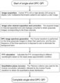
- Step 1 image acquisition under color multiplexed illumination: a high-contrast LCD TFT-LCD or a high-density programmable LED array is controlled by a computer through a serial port to display color multiplexed illumination pattern illumination samples.
- the illumination pattern is an annular illumination with red, green, blue colors, their asymmetry axis difference of 120°.
- the NA of the annular illumination is equal to the NA of the objective, and the intensity of the illumination is distributed sinusoidally according to the asymmetry axis.
- the illumination control is sent at the same time to generate a synchronous trigger signal to the color camera to collect a color sample image, noted as I c .
- Step 2 image color channel separation and correction: the color sample images are separated by color channel and color leakage correction is performed to obtain the intensity images of the samples corresponding to the red, green and blue channels I r,corr , I g,corr , I b,corr .
- Step 3 DPC image spectrum generation: the Fourier transform is performed on the three grayscale images I r,corr , I g,corr , I b,corr to obtain the spectrums distribution of the three images.
- the values of zero frequency of the three spectrums are set to zero to eliminate the effect of the background term, and the DPC image spectrum , , , of the sample is obtained.
- Step 4 PTF calculation: Based on the weak phase approximation condition, the PTF PTF r ( u ), PTF g ( u ), PTF b ( u ) corresponding to different wavelengths is calculated according to the parameters of the illumination function and the objective lens.
- Step 5 quantitative phase recovery: Based on PTF r ( u ), PTF g ( u ), PTF b ( u ) at different wavelengths and DPC image spectrum of the sample, the Tikhonov criterion is used for the inverse convolution calculation to obtain the high-resolution spectrum of the sample phase. The inverse Fourier transform is performed on this high-resolution spectrum to obtain the quantitative phase distribution of the sample.
- the significant advantages of the present invention are: (1) Rigorously deriving the isotropic PTF for three-axis DPC imaging, designing a three-axis optimal illumination pattern for DPC to achieve isotropic imaging, and improving the phase transfer response over the entire theoretical bandwidth of incoherent imaging. Compared with existing illumination schemes, the invention not only achieves isotropic imaging, but also significantly improves the phase contrast and imaging resolution. (2) Combining the color multiplexed illumination and the optimal triaxial illumination to achieve single-shot DPC imaging, which maximizes the imaging quality with real-time dynamic imaging efficiency, realizing real-time dynamic high-resolution and high-stability QPI.
- the TFT-LCD modulated illumination source enables color multiplexed illumination by simply adding an LCD module to a conventional microscope, which is compatible with any microscope system.
- the invention achieves the fastest imaging speed (single shot) and the best imaging quality at the same time.
- FIG. 1 is a flow chart of the invention.
- FIG. 2 is a schematic diagram of the system.
- FIG. 3 is a model schematic diagram of the color multiplexed illumination source in polar coordinates.
- FIG. 4 is a comparison of the imaging performance under single-shot DPC quantitative phase microscopy imaging with the color multiplexed illumination of the present invention and the existing uniform circular single-shot DPC imaging illumination.
- FIG. 5 is a plot of the final imaging results of a standard USAF resolution target using the present invention and a semicircular single-shot DPC QPI method under a 10x objective.
- FIG. 6 shows the final imaging results for in vitro unstained cervical cancer (Hela) live cells using color multiplexed single-shot DPC QPI under a 10x objective.
- the experimental platform of the present invention for DPC quantitative phase microscopy imaging method based on color multiplexed illumination can be built based on any commercial microscope system by simply adding a light source modulation module color LCD display illumination or programmable color LED array to the optical path.
- the schematic diagram of the microscope system is shown in FIG. 2 ( a ) , which includes a color multiplexed light source module (an assembly consisting of a mercury lamp, LCD, and a condenser), a sample, a microscope objective (achromatic objective), a tube lens, and a color camera.
- the color multiplexed light source module can adopt two structures.
- the first one is to use the microscope's own light source, LCD display and condenser lens as the illumination module, and the LCD is used to modulate the light source so that the light source irradiated on the sample is the color multiplexed pattern designed by the present invention.
- the second type uses LED as the illumination system, and it is directly controlled by the computer to display color multiplexed illumination pattern. Then, the colored light is concentrated on the sample after passing through the condenser lens.
- the LED array or LCD display includes a number of point light sources, they are regularly arranged to form a two-dimensional matrix. Each point source can be illuminated with three channels: red, green, and blue, with typical wavelengths of 632 nm for red, 522 nm for green, and 470 nm for blue. The typical value of center distance d between each point source is 1-10mm.
- the illumination module is positioned under the object stage and is typically spaced between 30-90mm from the upper surface of the object stage, with its central LED on the optical axis of the
- the drive implementation circuit to light up each of the point sources can be implemented using (but not limited to) existing technologies such as microcontrollers, ARM, or programmable logic devices, and the specific implementation methods can be found in the references (Baozeng Guo, Chunmiao Deng: FPGA-based LED display control system design [J]. Liquid Crystal and Display, 2010, 25(3):424-428). If the LCD display is used for system illumination, the LCD is used to replace the aperture diaphragm under the condenser lens in the original microscope.
- the illumination pattern of the invention is used as a spatial light filter.
- the technology used in the driving circuit is basically the same as that of the LED array, and the specific implementation method can be found in the references (Lin, F., Zhang, W. W.: Rheinberg illumination microscopy principle and system based on programmable LCD. Design. Journal of Optics, 2016, 8:237-243).
- Step 1 image acquisition under color multiplexed illumination: a high-contrast LCD TFT-LCD or a high-density programmable color LED array is controlled by a computer through a serial port to display a color multiplexed illumination pattern illumination sample, as shown in FIG. 2 ( b ) .
- the illumination pattern is a semi-annular illumination of three colors of red, green and blue with an asymmetric axis difference of 120° , where the NA of the semi-annular illumination is equal to the NA of the objective, and the illumination intensity is distributed sinusoidally.
- ⁇ , ⁇ denotes the radius and polar angle of the polar coordinate system, respectively
- ⁇ ( ⁇ —NA obj ) is the angle of the asymmetry axis of the illumination pattern of the three colors of red, green, and blue, respectively.
- the shape of the illumination pattern is expressed as a annulus of illumination NA matched with the NA of the objective lens. From this illumination function, it can be seen that the design of the present invention is satisfied as long as the angle of the three wavelength illumination patterns is 120° .
- a synchronous trigger signal is generated to the color camera while sending the illumination control, and then a color sample image is captured, as shown in FIG. 2 ( c ) , noted as I c .
- the invention uses the optimal illumination scheme combined with color multiplexed illumination to achieve single-shot DPC imaging, which significantly improves the isotropic degree of imaging, while greatly improving its low-frequency imaging contrast and high-frequency resolution.
- a second color sample image will be acquired by rotating the illumination pattern by 90° in any direction after the above acquisition process is completed, noted as I c, ⁇ .
- a single shot of color multiplexed illumination pattern is used as pattern 1 , which is rotated by 90° in any direction as pattern 2 .
- Two images are acquired using these two alternating illuminations. Phase recovery can be achieved using these two images to obtain a completely isotropic PTF and achieve a completely isotropic imaging resolution.
- Step 2 image color channel separation and correction: The color sample images are separated to three channels and corrected for color leakage to obtain the sample intensity images corresponding to the red, green, and blue channels I r,corr , I g,corr , I b,corr , as shown in FIG. 2 (d 1 ), FIG. 2 (d 2 ), and FIG. 2 (d 3 ).
- the two color sample images are acquired and the channel separation and correction are performed separately to obtain the sample intensity images of red, green and blue channels corresponding to the two images respectively I r,corr , I g,corr , I b,corr , I r, ⁇ ,corr , I g, ⁇ ,corr , I b, ⁇ ,corr .
- color LCDs or LEDs usually have a wide emission spectrum, and for most color image sensors, the spectral response of different color channels cannot be completely isolated. Therefore, the light of one color in the illumination may leak into other color channels and be detected by other color channels of the camera, which means that the single-channel image of a color sensor is actually a mixture of different channels.
- color multiplexed illumination the illumination light with three channels simultaneously illuminate the sample to acquire a color image, color leakage becomes more apparent due to the overlap of emission spectra (part of the spectral response of green light overlaps spectrally with the blue and red channels). Directly using the image after separating the channels for DPC phase recovery, the color leakage will lead to severe phase estimation errors.
- the present invention employs a color leakage correction method that represents the detector signal measured in the color channel as the sum of the light of the desired color and the light of other colors.
- the measured signals in the red, green, and blue channels can be written as:
- I r , I g , I b is the signal intensity of the red, green, and blue channels measured by the camera sensor, i.e., the intensity images of the red, green, and blue channels obtained by direct channel separation.
- I r,corr , I g,corr , I b,corr is the light intensity of the red, green, and blue channels incident on the camera sensor, i.e., the intensity of the image that should be brought into phase recovery after correction.
- the purpose of the color leakage correction is to obtain the value of each R n m so that I r,corr , I g,corr , I b,corr can be obtained from the image I c acquired by the camera .
- This image I c,l′ can be separated to obtain three images with different channels I l,r ′, I l,g ′, I l,b ′.
- the color image can be separated to obtain I r , I g , I b .
- the corrected light intensity image I r,corr , I g,corr , I b,corr for each wavelength can be obtained according to the following equation:
- the three images are used to calculate the spectral response matrix of the camera, which can be used to subsequently correct the images and effectively address the phase reconstruction errors caused by color leakage.
- This spectral response matrix reconfiguration is calculated only once for the same imaging system.
- Step 3 DPC image spectrum generation: Fourier transform is performed on the three channels of I r,corr , I g,corr , I b,corr to obtain the spectrum distribution of the three images.
- the value at zero frequency of the three spectrum is set as 0 to obtain the spectrum distribution of the DPC image of the sample under three channels, they are expressed as , , .
- the single channel sample intensity image I r,corr , I g,corr , I b,corr , , , corresponding to the two acquired images will be solved for their spectrum separately and the zero frequency of the spectrum will be removed for the elimination of the background term.
- Step 4 PTF calculation: Based on the weak phase approximation condition, the PTF PTF r ( ⁇ , ⁇ ) , PTF g ( ⁇ , ⁇ ) , PTF b ( ⁇ , ⁇ ) corresponding to different wavelengths are calculated according to the parameters of the illumination function and the objective lens.
- the PTFs corresponding to both illumination patterns need to be solved PTF r ( ⁇ , ⁇ ) , PTF g ( ⁇ , ⁇ ) , PTF b ( ⁇ , ⁇ ), PTF r, ⁇ ( ⁇ , ⁇ ) , PTF g, ⁇ ( ⁇ , ⁇ ) , PTF b, ⁇ ( ⁇ , ⁇ )
- ⁇ r , ⁇ g , ⁇ b is determined by the NA obj of the objective and the illumination wavelength ⁇ r , ⁇ g , ⁇ b which can be obtained by solving for the following equation:
- Step 5 sample quantitative phase recovery: according to PTF r ( ⁇ , ⁇ ) , PTF g ( ⁇ , ⁇ ) , PTF b ( ⁇ , ⁇ ) of different wavelengths and the DPC image spectrum , , , the Tikhonov criterion is used for the inverse convolution calculation to obtain the high-resolution spectrum of the sample phase. Then, the inverse Fourier transform is performed on this high-resolution spectrum to obtain the quantitative phase distribution ⁇ of the sample.
- k denotes different wavelength channels, red, green, blue.
- PTF ⁇ k ( ⁇ , ⁇ ) denotes the conjugate distribution of PTF k ( ⁇ , ⁇ ) .
- ⁇ k / ⁇ denotes the wavelength normalization coefficient. Because the phase and wavelength are inversely proportional, so in the color multiplexed illumination, it is necessary to normalize the wavelength to get a uniform phase distribution, here ⁇ denotes the normalized wavelength, which can be chosen as any wavelength. The blue illumination wavelength is chosen as the normalized wavelength.
- ⁇ is the normalization parameter, generally choose a smaller value, such as 0.01.
- FIG. 4 shows the PTFs under the existing single-shot DPC imaging illumination scheme and the present invention, including uniform circular, sinusoidal circular, and sinusoidal toroidal, and the asymmetric axis angle of all three illuminations is 120° . Simulations were performed using the same objective and illumination parameters to obtain the multi-axis synthetic PTF corresponding to each illumination pattern, as shown in FIG. 4 ( a 1 ), FIG. 4 ( a 2 ), and FIG. 4 ( a 3 ). Comparing these three PTFs, it can be found that under uniform circular illumination, the PTF has poor transfer responses, especially at the center low frequency and high frequency near 2NA obj .
- FIG. 4 ( c 1 ) and FIG. 4 ( c 2 ) show the differences in the PTF responses of FIG. 4 ( a 3 ) and FIG. 4 ( a 1 ), FIG. 4 ( a 3 ) and FIG. 4 ( a 2 ), respectively, and the enhancement of the PTF by the illumination scheme of the present invention can be clearly observed.
- FIG. 4 ( d 1 ) and FIG. 4 ( d 2 ) show the difference in the response of the PTF of FIG. 4 ( b 3 ) and FIG. 4 ( b 1 ), FIG. 4 ( b 3 ) and FIG. 4 ( b 2 ). It can be seen that the alternating scheme of the present invention significantly enhances the response of the PTF.
- FIG. 5 In order to verify the high resolution, high stability, and high contrast of the single-shot DPC QPI results based on color multiplexed illumination of the present invention, a comparison experiment was conducted using a standard USAF phase resolution target as a sample with uniform circular illumination and the method of the present invention. The experimental results are shown in FIG. 5 .
- FIG. 5 ( a ) and FIG. 5 ( c ) show the images acquired by the color multiplexed illumination of the present invention.
- the quantitative phase results obtained under uniform circular illumination are shown in FIG. 5 ( b 1 ) and
- FIG. 5 ( d 1 ), and the quantitative phase results of the present invention are shown in FIG. 5 ( b 2 ) and FIG. 5 ( d 2 ). Comparing FIG. 5 ( b 1 ) with FIG. 5 ( b 2 ) and FIG. 5 ( d 1 ) with FIG. 5 ( d 2 ), it can be found that better robustness, better contrast and higher resolution phase results are obtained under color multiplexed illumination of the present invention. The phase values at the highest resolution are further extracted and plotted to quantitatively compare the imaging performance of these two illuminations.
- FIG. 5 ( e ) shows the distribution of the curves at the highest resolution in FIG. 5 ( b 1 ) and FIG. 5 ( b 2 ).
- FIG. 5 ( f ) shows the quantitative phase distribution on the highest resolution in FIG. 5 ( d 1 ) and FIG. 5 ( d 2 ), and the comparison shows that the present invention achieves the theoretical highest resolution of 435nm, while this resolution cannot be recovered under uniform circular illumination.
- FIG. 6 ( a ) shows the reconstructed phase results in full field of view, and two regions of interest are selected for magnification, as shown in FIG. 6 ( b ) and FIG. 6 ( c ) .
- FIG. 6 ( d ) shows the phase of the cells at different moments.
Landscapes
- Physics & Mathematics (AREA)
- Engineering & Computer Science (AREA)
- General Physics & Mathematics (AREA)
- Multimedia (AREA)
- Theoretical Computer Science (AREA)
- Chemical & Material Sciences (AREA)
- Analytical Chemistry (AREA)
- Optics & Photonics (AREA)
- Computer Vision & Pattern Recognition (AREA)
- Microscoopes, Condenser (AREA)
- Spectrometry And Color Measurement (AREA)
Abstract
Description
S r(ρ,θ)=δ(ρ—NAobj)sin(θ+θr) S g(ρ,θ)=δ(ρ—NAobj)sin(θ+θg) S b(ρ,θ)=δ(ρ—NAobj)sin(θ+θb) ( θr+θg−120 ° , θb=θg+120 ° )
where Sr(ρ,θ) , Sg(ρ,θ) , Sb(ρ,θ) denotes the illumination functions corresponding to the three wavelengths of red, green, and blue, respectively. ρ, θ denotes the radius and polar angle of the polar coordinate system, respectively, and δ(ρ—NAobj) is the angle of the asymmetry axis of the illumination pattern of the three colors of red, green, and blue, respectively. The shape of the illumination pattern is expressed as a annulus of illumination NA matched with the NA of the objective lens. From this illumination function, it can be seen that the design of the present invention is satisfied as long as the angle of the three wavelength illumination patterns is 120° . A synchronous trigger signal is generated to the color camera while sending the illumination control, and then a color sample image is captured, as shown in
PTF r(ρ,θ)=sin(αr)sin(θ+θr) PTF g(ρ,θ)=sin(αg)sin(θ+θg) PTF b(ρ,θ)=sin(αb)sin(θ+θb) ( θr=θg −120° ,θb=θg+120° )
Claims (6)
S r(ρ,θ)=δ(ρ—NAobj)sin(θ+θr) S g(ρ,θ)=δ(ρ—NAobj)sin(θ+θg) S b(ρ,θ)=δ(ρ—NAobj)sin(θ+θb) ( θy+θg—120 ° , θb=θg+120° )
S r(ρ,θ)=δ(ρ—NAobj)sin(θ+θr) S g(ρ,θ)=δ(ρ—NAobj)sin(θ+θg) S b(ρ,θ)=δ(ρ—NAobj)sin(θ+θb) ( θy+θg−120 ° , θb=θg+120 ° )
Applications Claiming Priority (3)
| Application Number | Priority Date | Filing Date | Title |
|---|---|---|---|
| CN201910977145.X | 2019-10-15 | ||
| CN201910977145.XA CN112666697B (en) | 2019-10-15 | 2019-10-15 | Single-frame differential phase contrast quantitative phase imaging method based on color multiplex illumination |
| PCT/CN2020/109735 WO2021073245A1 (en) | 2019-10-15 | 2020-08-18 | Single-frame differential phase contrast quantitative phase imaging method based on color multiplexing illumination |
Publications (2)
| Publication Number | Publication Date |
|---|---|
| US20220366552A1 US20220366552A1 (en) | 2022-11-17 |
| US11893719B2 true US11893719B2 (en) | 2024-02-06 |
Family
ID=75400051
Family Applications (1)
| Application Number | Title | Priority Date | Filing Date |
|---|---|---|---|
| US17/766,088 Active 2041-01-06 US11893719B2 (en) | 2019-10-15 | 2020-08-18 | Single-shot differential phase contrast quantitative phase imaging method based on color multiplexed illumination |
Country Status (3)
| Country | Link |
|---|---|
| US (1) | US11893719B2 (en) |
| CN (1) | CN112666697B (en) |
| WO (1) | WO2021073245A1 (en) |
Families Citing this family (4)
| Publication number | Priority date | Publication date | Assignee | Title |
|---|---|---|---|---|
| CN116320775B (en) * | 2022-11-02 | 2025-12-23 | 南京理工大学智能计算成像研究院有限公司 | A method for compensating coherent effects based on the light intensity transmission equation |
| CN115774327B (en) * | 2022-11-22 | 2024-09-27 | 中国科学院光电技术研究所 | A quantitative differential phase contrast microscope integrating illumination modulation and pupil modulation |
| CN115980989B (en) * | 2023-01-09 | 2024-08-06 | 南开大学 | Single-frame quantitative phase tomography system and method based on microlens array |
| EP4492117A1 (en) * | 2023-07-12 | 2025-01-15 | Carl Zeiss Microscopy GmbH | Hybrid differential defocus phase contrast |
Citations (11)
| Publication number | Priority date | Publication date | Assignee | Title |
|---|---|---|---|---|
| US20160341945A1 (en) * | 2015-05-21 | 2016-11-24 | California Institute Of Technology | Laser-based fourier ptychographic imaging systems and methods |
| US9892812B2 (en) * | 2012-10-30 | 2018-02-13 | California Institute Of Technology | Fourier ptychographic x-ray imaging systems, devices, and methods |
| US9983397B2 (en) * | 2013-07-31 | 2018-05-29 | California Institute Of Technology | Aperture scanning fourier ptychographic imaging |
| US9998658B2 (en) * | 2013-08-22 | 2018-06-12 | California Institute Of Technology | Variable-illumination fourier ptychographic imaging devices, systems, and methods |
| CN108537842A (en) | 2017-12-29 | 2018-09-14 | 南京理工大学 | The heteropical correction of background and compensation method in differential phase contrast micro-imaging |
| CN109375358A (en) | 2018-11-28 | 2019-02-22 | 南京理工大学 | A Differential Phase Contrast Quantitative Phase Microimaging Method Based on Optimal Illumination Mode Design |
| US20190107655A1 (en) | 2016-04-15 | 2019-04-11 | The Regents Of The University Of California | Optical phase retrieval systems using color-multiplexed illumination |
| US20210191099A1 (en) * | 2019-12-24 | 2021-06-24 | National Taiwan University | System for quantitative differential phase contrast microscopy with isotropic transfer function |
| US11468557B2 (en) * | 2014-03-13 | 2022-10-11 | California Institute Of Technology | Free orientation fourier camera |
| US11555992B2 (en) * | 2017-08-04 | 2023-01-17 | Nanjing University Of Science And Technology | Programmable annular led illumination-based high efficiency quantitative phase microscopy imaging method |
| US11703672B2 (en) * | 2018-11-09 | 2023-07-18 | Leica Microsystems Cms Gmbh | Microscopic transmitted light contrasting method |
Family Cites Families (2)
| Publication number | Priority date | Publication date | Assignee | Title |
|---|---|---|---|---|
| CN107272178B (en) * | 2017-08-04 | 2019-06-21 | 南京理工大学 | Differential phase contrast microscopy imaging method based on semi-ring LED illumination |
| CN109581645B (en) * | 2018-11-22 | 2020-07-24 | 南京理工大学 | Phase contrast and differential interference phase contrast microscopic imaging method based on light intensity transmission equation |
-
2019
- 2019-10-15 CN CN201910977145.XA patent/CN112666697B/en active Active
-
2020
- 2020-08-18 WO PCT/CN2020/109735 patent/WO2021073245A1/en not_active Ceased
- 2020-08-18 US US17/766,088 patent/US11893719B2/en active Active
Patent Citations (12)
| Publication number | Priority date | Publication date | Assignee | Title |
|---|---|---|---|---|
| US9892812B2 (en) * | 2012-10-30 | 2018-02-13 | California Institute Of Technology | Fourier ptychographic x-ray imaging systems, devices, and methods |
| US9983397B2 (en) * | 2013-07-31 | 2018-05-29 | California Institute Of Technology | Aperture scanning fourier ptychographic imaging |
| US9998658B2 (en) * | 2013-08-22 | 2018-06-12 | California Institute Of Technology | Variable-illumination fourier ptychographic imaging devices, systems, and methods |
| US11468557B2 (en) * | 2014-03-13 | 2022-10-11 | California Institute Of Technology | Free orientation fourier camera |
| US20160341945A1 (en) * | 2015-05-21 | 2016-11-24 | California Institute Of Technology | Laser-based fourier ptychographic imaging systems and methods |
| US20190107655A1 (en) | 2016-04-15 | 2019-04-11 | The Regents Of The University Of California | Optical phase retrieval systems using color-multiplexed illumination |
| US11555992B2 (en) * | 2017-08-04 | 2023-01-17 | Nanjing University Of Science And Technology | Programmable annular led illumination-based high efficiency quantitative phase microscopy imaging method |
| CN108537842A (en) | 2017-12-29 | 2018-09-14 | 南京理工大学 | The heteropical correction of background and compensation method in differential phase contrast micro-imaging |
| US11703672B2 (en) * | 2018-11-09 | 2023-07-18 | Leica Microsystems Cms Gmbh | Microscopic transmitted light contrasting method |
| CN109375358A (en) | 2018-11-28 | 2019-02-22 | 南京理工大学 | A Differential Phase Contrast Quantitative Phase Microimaging Method Based on Optimal Illumination Mode Design |
| US11487096B2 (en) * | 2018-11-28 | 2022-11-01 | Nanjing University Of Science And Technology | Quantitative phase imaging method based on differential phase contrast with optimal lighting pattern design |
| US20210191099A1 (en) * | 2019-12-24 | 2021-06-24 | National Taiwan University | System for quantitative differential phase contrast microscopy with isotropic transfer function |
Non-Patent Citations (5)
| Title |
|---|
| Ding, "Design and Development of the Built-In Cell Dynamic 3D Microscopic Imaging System of the Incubator", Nanjing University of Science & Technology, 2018, pp. 18-28, Total 70 Pages. |
| Fan et al. "Optimal Illumination Scheme for Isotropic Quantitative Differential Phase Contrast Microscopy" Photonics Research, Aug. 2019, vol. 7, No. 8, pp. 890-904. |
| International Search Report (PCT/ISA/210) issued in PCT/CN2020/109735 dated Nov. 24, 2020. |
| Lee et al., "Color-coded LED microscopy for multi-contrast and quantitative phase-gradient imaging", Biomedical Optics Express 2015, vol. 6, No. 12, pp. 4912-4922, Total 11 pages. |
| Tian et al., "Quantitative differential phase contrast imaging in an LED array microscope", Optics Express, 2015, vol. 23, No. 9, pp. 11394-11403. |
Also Published As
| Publication number | Publication date |
|---|---|
| CN112666697A (en) | 2021-04-16 |
| US20220366552A1 (en) | 2022-11-17 |
| CN112666697B (en) | 2022-06-10 |
| WO2021073245A1 (en) | 2021-04-22 |
Similar Documents
| Publication | Publication Date | Title |
|---|---|---|
| US11893719B2 (en) | Single-shot differential phase contrast quantitative phase imaging method based on color multiplexed illumination | |
| US11487096B2 (en) | Quantitative phase imaging method based on differential phase contrast with optimal lighting pattern design | |
| CN107065159B (en) | A large field of view high resolution microscopic imaging device and iterative reconstruction method based on large illumination numerical aperture | |
| US11781966B2 (en) | 3D diffraction tomography microscopy imaging method based on LED array coded illumination | |
| CN107966801A (en) | A kind of high speed Fourier lamination imaging device and reconstructing method based on ring illumination | |
| Zhang et al. | Attention to region: Region-based integration-and-recalibration networks for nuclear cataract classification using AS-OCT images | |
| US20230359010A1 (en) | A miniaturized, low-cost, multi-contrast label-free microscope imaging system | |
| CN107490562B (en) | Ultra-high-speed three-dimensional refractive index image shooting and fluorescent structured light illuminating microscope system using wave surface shaper and using method thereof | |
| Sun et al. | Real-time subcellular imaging based on graphene biosensors | |
| Lee et al. | Color-coded LED microscopy for quantitative phase imaging: Implementation and application to sperm motility analysis | |
| CN109407297A (en) | A kind of multi-mode light field micro imaging method based on programmable LED array illumination | |
| Jiang et al. | Single-shot color-coded LED microscopy for quantitative differential phase contrast imaging | |
| CN118067001B (en) | A method for accurate correction of light source position combined with pupil function | |
| Gholami Mayani et al. | High-resolution polarization-sensitive Fourier ptychography microscopy using a high numerical aperture dome illuminator | |
| CN108537842B (en) | Method for correcting and compensating background nonuniformity in differential phase contrast microscopic imaging | |
| CN107272178A (en) | Differential phase contrast micro imaging method based on semicircular LED illumination | |
| CN111505817A (en) | Phase contrast microscope system based on polarization encoding and imaging method thereof | |
| US20250035903A1 (en) | System for quantitative differential phase contrast microscopy with isotropic transfer function | |
| CN110388882A (en) | Quantitative Differential Phase Contrast Microscopy System with Isotropic Transfer Function | |
| CN115774327B (en) | A quantitative differential phase contrast microscope integrating illumination modulation and pupil modulation | |
| Chen et al. | Time-lapse imaging using dual-color coded quantitative differential phase contrast microscopy | |
| CN115452743B (en) | Lens-free single-frame phase recovery method based on partial coherence LED illumination | |
| CN115602318B (en) | Microscopic imaging method based on chromatic dispersion and application thereof | |
| He et al. | Full Poincare mapping for ultra-sensitive polarimetry | |
| Peng et al. | A compact real-time quantitative phase imaging system |
Legal Events
| Date | Code | Title | Description |
|---|---|---|---|
| FEPP | Fee payment procedure |
Free format text: ENTITY STATUS SET TO UNDISCOUNTED (ORIGINAL EVENT CODE: BIG.); ENTITY STATUS OF PATENT OWNER: SMALL ENTITY |
|
| FEPP | Fee payment procedure |
Free format text: ENTITY STATUS SET TO SMALL (ORIGINAL EVENT CODE: SMAL); ENTITY STATUS OF PATENT OWNER: SMALL ENTITY |
|
| STPP | Information on status: patent application and granting procedure in general |
Free format text: DOCKETED NEW CASE - READY FOR EXAMINATION |
|
| STPP | Information on status: patent application and granting procedure in general |
Free format text: NON FINAL ACTION MAILED |
|
| STPP | Information on status: patent application and granting procedure in general |
Free format text: RESPONSE TO NON-FINAL OFFICE ACTION ENTERED AND FORWARDED TO EXAMINER |
|
| STPP | Information on status: patent application and granting procedure in general |
Free format text: NOTICE OF ALLOWANCE MAILED -- APPLICATION RECEIVED IN OFFICE OF PUBLICATIONS |
|
| STPP | Information on status: patent application and granting procedure in general |
Free format text: PUBLICATIONS -- ISSUE FEE PAYMENT VERIFIED |
|
| STCF | Information on status: patent grant |
Free format text: PATENTED CASE |