US11891787B2 - Automatic flushing device for electronic bidet having automatic flushing function for both water tank and direct flush valve toilet - Google Patents
Automatic flushing device for electronic bidet having automatic flushing function for both water tank and direct flush valve toilet Download PDFInfo
- Publication number
- US11891787B2 US11891787B2 US17/791,886 US202117791886A US11891787B2 US 11891787 B2 US11891787 B2 US 11891787B2 US 202117791886 A US202117791886 A US 202117791886A US 11891787 B2 US11891787 B2 US 11891787B2
- Authority
- US
- United States
- Prior art keywords
- valve
- opening
- toilet
- automatic flushing
- water
- Prior art date
- Legal status (The legal status is an assumption and is not a legal conclusion. Google has not performed a legal analysis and makes no representation as to the accuracy of the status listed.)
- Active
Links
- XLYOFNOQVPJJNP-UHFFFAOYSA-N water Substances O XLYOFNOQVPJJNP-UHFFFAOYSA-N 0.000 title claims abstract description 107
- 238000011010 flushing procedure Methods 0.000 title claims abstract description 95
- 238000003825 pressing Methods 0.000 claims description 16
- 238000007789 sealing Methods 0.000 claims description 11
- 238000007599 discharging Methods 0.000 claims description 8
- 238000012856 packing Methods 0.000 claims description 5
- 238000004891 communication Methods 0.000 claims description 3
- 230000008878 coupling Effects 0.000 claims description 3
- 238000010168 coupling process Methods 0.000 claims description 3
- 238000005859 coupling reaction Methods 0.000 claims description 3
- 238000005406 washing Methods 0.000 description 14
- 238000000034 method Methods 0.000 description 10
- 230000000694 effects Effects 0.000 description 7
- 210000003608 fece Anatomy 0.000 description 5
- 210000002700 urine Anatomy 0.000 description 5
- 238000004519 manufacturing process Methods 0.000 description 3
- 238000001514 detection method Methods 0.000 description 2
- 230000007257 malfunction Effects 0.000 description 2
- 230000009977 dual effect Effects 0.000 description 1
- 230000005611 electricity Effects 0.000 description 1
- 238000012986 modification Methods 0.000 description 1
- 230000004048 modification Effects 0.000 description 1
Images


Classifications
-
- E—FIXED CONSTRUCTIONS
- E03—WATER SUPPLY; SEWERAGE
- E03D—WATER-CLOSETS OR URINALS WITH FLUSHING DEVICES; FLUSHING VALVES THEREFOR
- E03D5/00—Special constructions of flushing devices, e.g. closed flushing system
- E03D5/10—Special constructions of flushing devices, e.g. closed flushing system operated electrically, e.g. by a photo-cell; also combined with devices for opening or closing shutters in the bowl outlet and/or with devices for raising/or lowering seat and cover and/or for swiveling the bowl
-
- E—FIXED CONSTRUCTIONS
- E03—WATER SUPPLY; SEWERAGE
- E03D—WATER-CLOSETS OR URINALS WITH FLUSHING DEVICES; FLUSHING VALVES THEREFOR
- E03D1/00—Water flushing devices with cisterns ; Setting up a range of flushing devices or water-closets; Combinations of several flushing devices
- E03D1/30—Valves for high or low level cisterns; Their arrangement ; Flushing mechanisms in the cistern, optionally with provisions for a pre-or a post- flushing and for cutting off the flushing mechanism in case of leakage
- E03D1/34—Flushing valves for outlets; Arrangement of outlet valves
-
- E—FIXED CONSTRUCTIONS
- E03—WATER SUPPLY; SEWERAGE
- E03D—WATER-CLOSETS OR URINALS WITH FLUSHING DEVICES; FLUSHING VALVES THEREFOR
- E03D1/00—Water flushing devices with cisterns ; Setting up a range of flushing devices or water-closets; Combinations of several flushing devices
- E03D1/38—Adaptations or arrangements of flushing pipes
-
- E—FIXED CONSTRUCTIONS
- E03—WATER SUPPLY; SEWERAGE
- E03D—WATER-CLOSETS OR URINALS WITH FLUSHING DEVICES; FLUSHING VALVES THEREFOR
- E03D3/00—Flushing devices operated by pressure of the water supply system flushing valves not connected to the water-supply main, also if air is blown in the water seal for a quick flushing
-
- E—FIXED CONSTRUCTIONS
- E03—WATER SUPPLY; SEWERAGE
- E03D—WATER-CLOSETS OR URINALS WITH FLUSHING DEVICES; FLUSHING VALVES THEREFOR
- E03D5/00—Special constructions of flushing devices, e.g. closed flushing system
- E03D5/02—Special constructions of flushing devices, e.g. closed flushing system operated mechanically or hydraulically (or pneumatically) also details such as push buttons, levers and pull-card therefor
-
- E—FIXED CONSTRUCTIONS
- E03—WATER SUPPLY; SEWERAGE
- E03D—WATER-CLOSETS OR URINALS WITH FLUSHING DEVICES; FLUSHING VALVES THEREFOR
- E03D5/00—Special constructions of flushing devices, e.g. closed flushing system
- E03D5/10—Special constructions of flushing devices, e.g. closed flushing system operated electrically, e.g. by a photo-cell; also combined with devices for opening or closing shutters in the bowl outlet and/or with devices for raising/or lowering seat and cover and/or for swiveling the bowl
- E03D5/105—Special constructions of flushing devices, e.g. closed flushing system operated electrically, e.g. by a photo-cell; also combined with devices for opening or closing shutters in the bowl outlet and/or with devices for raising/or lowering seat and cover and/or for swiveling the bowl touchless, e.g. using sensors
-
- E—FIXED CONSTRUCTIONS
- E03—WATER SUPPLY; SEWERAGE
- E03D—WATER-CLOSETS OR URINALS WITH FLUSHING DEVICES; FLUSHING VALVES THEREFOR
- E03D9/00—Sanitary or other accessories for lavatories ; Devices for cleaning or disinfecting the toilet room or the toilet bowl; Devices for eliminating smells
- E03D9/08—Devices in the bowl producing upwardly-directed sprays; Modifications of the bowl for use with such devices ; Bidets; Combinations of bowls with urinals or bidets; Hot-air or other devices mounted in or on the bowl, urinal or bidet for cleaning or disinfecting
-
- F—MECHANICAL ENGINEERING; LIGHTING; HEATING; WEAPONS; BLASTING
- F16—ENGINEERING ELEMENTS AND UNITS; GENERAL MEASURES FOR PRODUCING AND MAINTAINING EFFECTIVE FUNCTIONING OF MACHINES OR INSTALLATIONS; THERMAL INSULATION IN GENERAL
- F16K—VALVES; TAPS; COCKS; ACTUATING-FLOATS; DEVICES FOR VENTING OR AERATING
- F16K31/00—Actuating devices; Operating means; Releasing devices
- F16K31/02—Actuating devices; Operating means; Releasing devices electric; magnetic
- F16K31/04—Actuating devices; Operating means; Releasing devices electric; magnetic using a motor
-
- F—MECHANICAL ENGINEERING; LIGHTING; HEATING; WEAPONS; BLASTING
- F16—ENGINEERING ELEMENTS AND UNITS; GENERAL MEASURES FOR PRODUCING AND MAINTAINING EFFECTIVE FUNCTIONING OF MACHINES OR INSTALLATIONS; THERMAL INSULATION IN GENERAL
- F16K—VALVES; TAPS; COCKS; ACTUATING-FLOATS; DEVICES FOR VENTING OR AERATING
- F16K47/00—Means in valves for absorbing fluid energy
- F16K47/02—Means in valves for absorbing fluid energy for preventing water-hammer or noise
-
- Y—GENERAL TAGGING OF NEW TECHNOLOGICAL DEVELOPMENTS; GENERAL TAGGING OF CROSS-SECTIONAL TECHNOLOGIES SPANNING OVER SEVERAL SECTIONS OF THE IPC; TECHNICAL SUBJECTS COVERED BY FORMER USPC CROSS-REFERENCE ART COLLECTIONS [XRACs] AND DIGESTS
- Y02—TECHNOLOGIES OR APPLICATIONS FOR MITIGATION OR ADAPTATION AGAINST CLIMATE CHANGE
- Y02A—TECHNOLOGIES FOR ADAPTATION TO CLIMATE CHANGE
- Y02A20/00—Water conservation; Efficient water supply; Efficient water use
- Y02A20/40—Protecting water resources
Definitions
- the present disclosure relates to an automatic flushing device for an electronic bidet, in which the automatic flushing device has an automatic flushing function and is for both a water tank toilet and a direct flush valve toilet. More particularly, in contrast to existing bidets, which are produced separately for the water tank toilet and the direct flush valve toilet in order to realize the automatic flushing function to the water tank toilet and the direct flush valve toilet, the automatic flushing device for the electronic bidet enables a single bidet to be capable of being used in both the water tank toilet and the direct flush valve toilet.
- a toilet is mounted in a lavatory of a home or a building, and is configured such that urine and feces are discharged to a septic tank together with washing water that is drained by pressing a lever after a user uses the toilet.
- an automatic flushing bidet having a dual opening and closing valve and having a function of supplying water to the bidet by using water in a pressure chamber of a flush valve, in which the bidet is used in a direct flush valve toilet and is capable of detecting a user and washing out urine and feces according to a control of the bidet rather than a manual operation of a lever, has been registered in Korean Patent No. 10-1198901 (hereinafter, referred to as ‘related art document 1’).
- a water passage is open by a motor that is rotated in a forward direction according to the control of a control unit and, at the same time, water in the pressure chamber of the flush valve is discharged to the toilet, thereby washing out urine and feces. Further, the water passage is closed by the motor that is rotated in a backward direction according to the control of the control unit, water is stored in the pressure chamber of the flush valve, and the motor waits for the next operation.
- the related art document 1 has a problem in that the bidet in the related art document 1 can be mounted only in the direct flush valve toilet.
- the flush valve apparatus opens and closes a water passage by a solenoid valve according to a control of a control unit, and discharges water in a pressure chamber of a flush valve, thereby flushing out water in the toilet.
- the related art document 2 has a problem in that the flush valve apparatus can be mounted only in a direct flush valve toilet. Further, although a water supplying hole of a piston of a conventional flush valve is enlarged in order to use the bidet and water is supplied to the bidet and also a flushing function is performed, there is a problem that a water hammer phenomenon occurs since the enlarged water supplying hole of the piston is directly closed when the solenoid valve is operated.
- the method of controlling the bidet uses a switching valve of the bidet and does not add a valve, and is capable of performing a washing operation and a bidet operation of the bidet by using washing water in a pressure chamber of a flush valve body in a direct flush valve toilet that is provided with the flush valve. Further, the method of controlling the bidet performs a washing operation of the toilet by automatically distinguishing urine and feces after a user uses the toilet. In addition, the method of preventing the water hammer phenomenon is capable of preventing the water hammer phenomenon after the washing operation of the toilet is performed.
- water in the pressure chamber is primarily passing through a solenoid valve and is secondarily passing through a bidet hot water tank and then is tertiarily passing through a bidet washing switching valve, thereby performing an automatic flushing. Therefore, water is not capable of being flushed out directly, and also the methods in the related art document 3 can be applied only in a direct flush valve toilet. Further, in a low water pressure state, since water is flushed out in three stages, a pressure loss occurs due to loads that are separately applied to the water, so that there is a problem that a smooth flushing is not performed.
- a wire type automatic flushing system which is related to an automatic flushing system of a water tank toilet, has been registered in Korean Patent No. 10-1190258 (hereinafter, referred to as ‘related art document 4’). More particularly, in the related art document 4, a length of a wire is adjusted such that a siphon cover is not pulled to an upper portion of a drainage pipe of an overflow pipe. Further, after a user uses the toilet, the wire is wound by a rotation of a motor and the siphon cover is rotated upward around an axis of the overflow pipe, so that the drainage pipe is open. Furthermore, water stored in a tank is drained to the drainage pipe that is open, thereby washing out urine and feces.
- the related art document 4 has a problem in that the system of the related art document 4 can be applied only in the water tank toilet.
- products in the related art documents 1 to 4 are developed of a flushing apparatus and a control unit which are capable of being applied to only one toilet among a water tank toilet and a direct flush valve toilet, and are manufactured and managed as two products, so that there is a problem that cost is increased.
- an objective of the present disclosure is to provide an automatic flushing device for an electronic bidet, in which the automatic flushing device has an automatic flushing function and is for both a water tank toilet and a direct flush valve toilet, the automatic flushing device being capable of being mounted in both the water tank toilet and the direct flush valve toilet.
- another objective of the present disclosure is to provide an automatic flushing device for an electronic bidet, in which the automatic flushing device has an automatic flushing function and is for both a water tank toilet and a direct flush valve toilet, the automatic flushing device being capable of increasing reliability of a product by preventing a malfunction of a stepping motor since the stepping motor is mounted inside the electronic bidet.
- Still another objective of the present disclosure is to provide an automatic flushing device for an electronic bidet, in which the automatic flushing device has an automatic flushing function and is for both a water tank toilet and a direct flush valve toilet, the automatic flushing device having an increased work efficiency since a structure of lifting a water sealing cover is simplified, so that productivity is increased and manufacturing cost is reduced, thereby increasing product competitiveness.
- yet another objective of the present disclosure is to provide an automatic flushing device for an electronic bidet, in which the automatic flushing device has an automatic flushing function and is for both a water tank toilet and a direct flush valve toilet, and in which the automatic flushing device does not use a method switching a switching valve so that water is passing through a conventional flush valve, a solenoid valve, and a hot water tank, the automatic flushing device being configured such that water is directly controlled at a pressure chamber of a flush valve by the automatic flushing device, thereby being capable of smoothly flushing out water.
- an objective of the present disclosure is to provide an automatic flushing device for an electronic bidet, in which the automatic flushing device has an automatic flushing function and is for both a water tank toilet and a direct flush valve toilet.
- the automatic flushing device includes: a stepping motor configured such that whether a user is in a sitting position or a standing up position is detected by a control unit of the electronic bidet and the stepping motor is rotated by a control signal set from the control unit; a roller portion for flushing mounted at a rotary shaft of the stepping motor, the roller portion for flushing being configured such that a roller is rotated by the control signal of the control unit and a wire is wound and unwound, thereby opening and closing a water sealing cover or pressing an opening and closing valve; and the opening and closing valve mounted at a casing of the stepping motor, the opening and closing valve being configured such that a flow path of a valve body is open by a rotation of a pressing member when the opening and closing valve is applied to the direct flush valve toilet, thereby discharging water in a pressure chamber of a flush valve to an inner portion of a toilet body and flushing out the water.
- the stepping motor may be configured to slow down a rotational speed of the roller such that a water hammer phenomenon is prevented.
- the roller portion for flushing may include: the roller fixed to the rotary shaft; the wire having a first side end fixed to the roller, the wire being configured to be wound and unwound while being guided by a tube that surrounds an outside of the wire; and the pressing member which protrudes downward on the roller and which is configured to press an opening and closing pin of the opening and closing valve.
- the automatic flushing device may further include a tube fixture which is fixed to an upper portion of the stepping motor and which fixes the tube.
- the opening and closing valve may include: the valve body having an inlet port and an outlet port that are in communication with each other; a fixing hook coupled to a fixing guide space that is formed on the stepping motor, thereby fixing the valve body to the stepping motor; a flush rod coupled to an inner portion of the valve body, the flush rod being configured such that a rod packing is mounted at an end portion of the flush rod so that the outlet port is open and closed by a pressing operation of an opening and closing pin; a valve cover which accommodates the flush rod and which is closely fixed to a rear end portion of the valve body; a spring mounted between the flush rod and the valve cover; the opening and closing pin mounted on an end portion of the valve body such that the opening and closing pin is capable of being slid, the opening and closing pin being configured to apply or release a pressure to the flush rod; a guide cover which is closely fixed to the end portion of the valve body and which guides the opening and closing pin; a water supplying hose connected to the inlet port; and a water discharging hose connected to the
- valve cover and the guide cover may be fixed to the valve body by being coupled in a rotational coupling manner.
- the present disclosure is capable of being applied to both two types of toilets that are a water tank toilet and a direct flush valve toilet. Therefore, when the automatic flushing device of the present disclosure is manufactured, only one product can be manufactured, so that economic feasibility may be increased since productivity is increased and manufacturing cost is reduced. In addition, since the two types do not required to be distinguished when the automatic flushing device of the present disclosure is manufactured, there is an effect that economic feasibility may be additionally increased due to the simplification of product management.
- the present disclosure is capable of being smoothly operated regardless of a low water pressure state or a high water pressure state, and also there is an effect that economic feasibility is increased since consumption of electricity may be reduced.
- the present disclosure does not use the method switching a switching valve so that water is passing through a conventional flush valve, a solenoid valve, and a hot water tank, water is directly controlled at the pressure chamber of the flush valve by the automatic flushing device, so that there is an effect that the flushing is smoothly performed.
- the stepping motor since the stepping motor is mounted inside the electronic bidet, malfunction may be prevented and electric shock accident may be reduced, so that there is an effect that the present disclosure may be safely used.
- FIG. 1 is a perspective view illustrating a state in which the present disclosure is mounted in an electronic bidet.
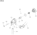
- FIG. 2 is an exploded perspective view illustrating the present disclosure.
- FIG. 3 is an exploded perspective view illustrating an opening and closing valve of the present disclosure.
- FIG. 4 is a plan view illustrating a configuration of the present disclosure.
- FIG. 5 is a front view illustrating the configuration of the present disclosure.
- FIG. 6 is a view illustrating a state in which the present disclosure is applied to a water tank toilet.
- FIG. 7 is a view illustrating a state in which the present disclosure is applied to a direct flush valve toilet.
- FIGS. 8 and 9 are views illustrating an operation state in which a water sealing cover is rotated upward and a drainage pipe is open according to the present disclosure.
- FIGS. 10 and 11 are views illustrating an operation state in which the water sealing cover is rotated downward and the drainage pipe is closed according to the present disclosure.
- FIGS. 12 to 14 are views illustrating an operation state in which water in a pressure chamber of a flush valve is discharged to a toilet body and is flushed out according to the present disclosure.
- FIGS. 15 and 16 are views illustrating an operation state in which the pressure chamber of the flush valve is closed according to the present disclosure.
- FIG. 1 is a perspective view illustrating a state in which the present disclosure is mounted in an electronic bidet
- FIG. 2 is an exploded perspective view illustrating the present disclosure.
- an automatic flushing device for an electronic bidet in which the automatic flushing device has an automatic flushing function and is for both a water tank toilet and a direct flush valve toilet, includes a stepping motor 100 , a roller portion 200 for flushing, and an opening and closing valve 300 . Further, the automatic flushing device is mounted inside the electronic bidet.
- the stepping motor 100 , the roller portion 200 for flushing, and the opening and closing valve 300 are not individually separated, but are integrally manufactured, and are configured such that the stepping motor 100 , the roller portion 200 for flushing, and the opening and closing valve 300 are capable of being used in both the water tank toilet and the direct flush valve toilet, without distinction.
- the stepping motor 100 has an outer portion provided with a casing so that the stepping motor 100 is fixed to an inner portion of the electronic bidet 1 , and the casing has a structure in which a motor is mounted inside the casing. Further, the stepping motor 100 is driven by a control signal detected through a control unit (not illustrated) provided at the electronic bidet 1 .
- the stepping motor 100 is controlled by the control unit such that the stepping motor 100 is rotated in a constant speed. Further, when the roller portion 200 for flushing is returned, the stepping motor 100 is controlled by the control unit such that the stepping motor 100 is rotated slower than a speed of the stepping motor at the time when the roller portion 200 for flushing is rotated for performing the flushing function.
- roller portion 200 for flushing is coupled to a rotary shaft 110 of the stepping motor 100 , and is configured to be rotated, thereby opening and closing a water sealing cover of the water tank toilet.
- the roller portion 200 for flushing includes a roller 210 , a wire 220 , and a pressing member 230 . Further, the roller 210 is coupled to the rotary shaft 110 and fixes a first side end portion of the wire 220 , thereby being configured to wound or unwound the wire 220 .
- the first side end portion of the wire 220 is fixed to the roller 210 and a second side end portion of the wire 220 is connected to the water sealing cover 30 provided inside a water tank 20 .
- the end portions of the wire 220 may be cut or may remain such that the end portions of the wire 220 are positioned inside the electronic bidet.
- the pressing member 230 protrudes downward on a lower surface of the roller 210 , and serves to press an opening and closing pin 360 of the opening and closing valve 300 .
- a tube 221 is provided outside the wire 220 so as to surround and protect the wire 220 and also to guide a movement of the wire 220 when the roller 210 is rotated and returned. Further, the tube 221 may be fixed to a tube fixture 240 that is fixed to an upper portion of the casing of the stepping motor 100 .
- the opening and closing valve 300 is mounted at the casing of the stepping motor 100 . Further, when the opening and closing valve 300 is applied to the direct flush valve toilet, the opening and closing valve 300 is configured to open a flow path of an inlet port 311 and an outlet port 312 of a valve body 310 , and is configured to discharge water stored in a pressure chamber of a flush valve to an inner portion of a toilet body 10 , thereby flushing out water.
- the valve body 310 of the opening and closing valve 300 has an inner center portion which is penetrated, and the inlet port 311 is formed at a first side of the valve body 310 and the outlet port 312 is formed at a lower portion of the valve body 310 , so that the inlet port 311 and the outlet port 312 are in communication with each other.
- a first side end portion of a water supplying hose 380 is connected to the inlet port 311 , and a second side end portion of the water supplying hose 380 is connected to the pressure chamber 50 of the flush valve 40 .
- a first side end portion of a water discharging hose 390 is connected to the outlet port 312 , and a second side end portion of the water discharging hose 390 is connected to the inner portion of the toilet body 10 .
- a fixing hook 320 is formed at the lower portion of the valve body 310 , and the fixing hook 320 is coupled to a fixing guide space 321 formed at the casing of the stepping motor 100 , thereby fixing the valve body 310 .
- a flush rod 330 having an end portion on which a rod packing 331 is mounted is coupled to an inner portion of the valve body 310 , and is configured to open and close the outlet port 312 according to whether or not the opening and closing pin 360 is pressed, the outlet port 312 being formed at the valve body 310 .
- a valve cover 340 is fixed to a rear end portion of the valve body 310 , and the valve cover 340 prevents the flush rod 330 from separating and guides the flush rod 330 so that the flush rod 330 is smoothly slid.
- a spring 350 is mounted between the flush rod 330 and the valve body 340 , thereby applying an elastic force to the flush rod 330 .
- the opening and closing pin 360 is mounted on an end portion of the valve body 310 such that the opening and closing pin 360 is capable of being slid. Further, the opening and closing pin 360 presses the rod packing 331 of the flush rod 330 by a pressure of the pressing member 230 of the roller portion 200 for flushing, and is returned by a returning force of the spring 350 when the pressure is released.
- a guide cover 370 is fixed to the end portion of the valve body 310 , and the guide cover 370 prevents water leakage and also guides a movement of the opening and closing pin 360 .
- protrusions are formed on outer circumferential surfaces of the valve cover 340 and the guide cover 370 , and groove portions are formed on the valve body 310 , so that the valve cover 340 and the guide cover 370 are coupled to the valve body 310 in a rotational coupling manner and are capable of being closely fixed to the valve body 310 .
- the present disclosure may be applied to both the water tank toilet and the direct flush valve toilet.
- First, an operation process of the present disclosure that is applied to the water tank toilet will be described in detail.
- the control unit senses whether or not the user is separated from the toilet. Then, according to a detection signal, the control unit applies power and drives the stepping motor 100 .
- the roller 210 of the roller portion 200 for flushing is rotated in a forward direction at the same time.
- the wire 220 is wound on the roller 210 and, at the same time, the water sealing cover 30 connected to the wire 220 is rotated upward around an axis and opens a drainage pipe, and water stored in the water tank 20 is drained to the toilet body 10 , thereby performing the flushing.
- the stepping motor 100 is rotated in a backward direction by a control of the control unit and, at the same time, the roller 210 is rotated in the backward direction and unwounds the wire 220 . Further, the water sealing cover 30 in which a supporting force is released when the wire 220 is unwound is rotated downward around the axis and closes the drainage pipe, and waits for the next operation.
- the control unit senses whether or not the user is separated from the toilet. Then, according to a detection signal, the control unit applies power and drives the stepping motor 100 .
- the pressing member 230 that protrudes on the lower portion of the roller 210 presses the end portion of the opening and closing pin 360 of the opening and closing valve 300 .
- the rear end portion of the opening and closing pin 360 presses the rod packing 331 of the flush rod 330 . Therefore, the flush rod 330 compresses the spring 350 by moving inside the valve cover 340 and, at the same time, opens the outlet port 312 .
- Water that has introduced into the inlet port 311 is discharged to the outlet port 312 , and the water is discharged to the inner portion of the toilet body 10 along the water discharging hose 390 , so that the flushing is performed.
- the stepping motor 100 when the flushing is completed, the stepping motor 100 is returned by being rotated in the backward direction by the control of the control unit and, at the same time, the pressing member 230 is separated from the opening and closing pin 360 . At this time, the stepping motor 100 is rotated at a speed that is slower than a speed at the time when the stepping motor 100 is rotated for performing the flushing, so that a water hammer phenomenon may be prevented.
Landscapes
- Engineering & Computer Science (AREA)
- Health & Medical Sciences (AREA)
- Public Health (AREA)
- Life Sciences & Earth Sciences (AREA)
- Hydrology & Water Resources (AREA)
- Water Supply & Treatment (AREA)
- General Engineering & Computer Science (AREA)
- Aviation & Aerospace Engineering (AREA)
- Molecular Biology (AREA)
- Epidemiology (AREA)
- Mechanical Engineering (AREA)
- Sanitary Device For Flush Toilet (AREA)
Abstract
Description
Claims (6)
Applications Claiming Priority (3)
| Application Number | Priority Date | Filing Date | Title |
|---|---|---|---|
| KR10-2020-0003667 | 2020-01-10 | ||
| KR1020200003667A KR102195888B1 (en) | 2020-01-10 | 2020-01-10 | auto-flushing device of electronic bidet with auto-flushing fuction combined use hand-operating toilet bowl and water tank toilet bowl |
| PCT/KR2021/000097 WO2021141366A1 (en) | 2020-01-10 | 2021-01-06 | Automatic flushing device for electronic bidet having automatic flushing function for both water tank and direct flush valve toilet |
Publications (2)
| Publication Number | Publication Date |
|---|---|
| US20230030631A1 US20230030631A1 (en) | 2023-02-02 |
| US11891787B2 true US11891787B2 (en) | 2024-02-06 |
Family
ID=74086848
Family Applications (1)
| Application Number | Title | Priority Date | Filing Date |
|---|---|---|---|
| US17/791,886 Active US11891787B2 (en) | 2020-01-10 | 2021-01-06 | Automatic flushing device for electronic bidet having automatic flushing function for both water tank and direct flush valve toilet |
Country Status (3)
| Country | Link |
|---|---|
| US (1) | US11891787B2 (en) |
| KR (1) | KR102195888B1 (en) |
| WO (1) | WO2021141366A1 (en) |
Families Citing this family (2)
| Publication number | Priority date | Publication date | Assignee | Title |
|---|---|---|---|---|
| KR102195888B1 (en) * | 2020-01-10 | 2020-12-28 | 주식회사 에어붐 | auto-flushing device of electronic bidet with auto-flushing fuction combined use hand-operating toilet bowl and water tank toilet bowl |
| KR102733842B1 (en) | 2022-02-04 | 2024-11-25 | 에스케이매직 주식회사 | Bidet Device |
Citations (5)
| Publication number | Priority date | Publication date | Assignee | Title |
|---|---|---|---|---|
| US20070079432A1 (en) * | 2005-10-11 | 2007-04-12 | Isaak Shoikhet | Converting device for automatic toilet flushing and air deodorizing |
| KR100735881B1 (en) | 2006-11-30 | 2007-07-04 | 주식회사 자동물내림 | Automatic flushing system of flush valve direct type toilet equipped with water supply to guide water supply to bidet |
| KR20120084477A (en) | 2011-01-20 | 2012-07-30 | 베스트오토앤시트 주식회사 | Flush valve pressure rooms equipped with a water feature using the bidet water supply shut off valve dual automatic flushing bidet |
| KR101190258B1 (en) | 2011-05-18 | 2012-10-12 | 베스트오토앤시트 주식회사 | Wire type auto flushing system |
| US20150000026A1 (en) * | 2012-06-27 | 2015-01-01 | sigmund lindsay clements | Touch Free User Recognition Assembly For Activating A User's Smart Toilet's Devices |
Family Cites Families (3)
| Publication number | Priority date | Publication date | Assignee | Title |
|---|---|---|---|---|
| KR101132763B1 (en) | 2011-05-12 | 2012-05-09 | (주)엔와이엔 | flush valve equipment capable of using selectively auto flushing devices and bidet |
| KR101198900B1 (en) | 2012-04-30 | 2012-11-07 | 김동근 | Method for controlling bidet and method for preventing water hammer of bidet |
| KR102195888B1 (en) * | 2020-01-10 | 2020-12-28 | 주식회사 에어붐 | auto-flushing device of electronic bidet with auto-flushing fuction combined use hand-operating toilet bowl and water tank toilet bowl |
-
2020
- 2020-01-10 KR KR1020200003667A patent/KR102195888B1/en active Active
-
2021
- 2021-01-06 WO PCT/KR2021/000097 patent/WO2021141366A1/en not_active Ceased
- 2021-01-06 US US17/791,886 patent/US11891787B2/en active Active
Patent Citations (5)
| Publication number | Priority date | Publication date | Assignee | Title |
|---|---|---|---|---|
| US20070079432A1 (en) * | 2005-10-11 | 2007-04-12 | Isaak Shoikhet | Converting device for automatic toilet flushing and air deodorizing |
| KR100735881B1 (en) | 2006-11-30 | 2007-07-04 | 주식회사 자동물내림 | Automatic flushing system of flush valve direct type toilet equipped with water supply to guide water supply to bidet |
| KR20120084477A (en) | 2011-01-20 | 2012-07-30 | 베스트오토앤시트 주식회사 | Flush valve pressure rooms equipped with a water feature using the bidet water supply shut off valve dual automatic flushing bidet |
| KR101190258B1 (en) | 2011-05-18 | 2012-10-12 | 베스트오토앤시트 주식회사 | Wire type auto flushing system |
| US20150000026A1 (en) * | 2012-06-27 | 2015-01-01 | sigmund lindsay clements | Touch Free User Recognition Assembly For Activating A User's Smart Toilet's Devices |
Also Published As
| Publication number | Publication date |
|---|---|
| US20230030631A1 (en) | 2023-02-02 |
| WO2021141366A1 (en) | 2021-07-15 |
| KR102195888B1 (en) | 2020-12-28 |
Similar Documents
| Publication | Publication Date | Title |
|---|---|---|
| US11891787B2 (en) | Automatic flushing device for electronic bidet having automatic flushing function for both water tank and direct flush valve toilet | |
| CN1422368A (en) | Automatic flush valve | |
| CN108071149B (en) | Toilet flushing method | |
| CN110629839B (en) | Control system for automatically controlling water inlet and outlet of water tank | |
| JP2000517016A (en) | Method and apparatus for operating a flushing device such as a toilet connected to a vacuum type sewage device and a discharge valve | |
| CN217782262U (en) | Drain valve device | |
| CN114775744B (en) | Drain valve device | |
| CN219909206U (en) | Flushing structure and closestool | |
| US20230065471A1 (en) | Flush water tank device and flush toilet apparatus provided with the same | |
| KR102195889B1 (en) | Hand-operating toilet bowl and water tank toilet bowl combined use auto-flushing release device | |
| KR101207635B1 (en) | Toilet flushing device | |
| KR100959693B1 (en) | Toilet seat equipped with a system for supplying water to toilets with no power to the automatic flushing device of the toilet using water pressure and human body load | |
| KR101198901B1 (en) | Flush valve pressure rooms equipped with a water feature using the bidet water supply shut off valve dual automatic flushing bidet | |
| CN116537325B (en) | Flushing structure and closestool | |
| KR20100002791A (en) | Hand-operated lever of chamber pot used to water pressure | |
| JP2001050419A (en) | Valve device | |
| CN113775012B (en) | Flushing device for toilet | |
| KR200206147Y1 (en) | Water saving device of toilet | |
| CN113775006B (en) | Water supply and drainage control mechanism of toilet bowl | |
| JP7730463B2 (en) | Flush toilet device | |
| US12264470B2 (en) | Water supply system of toilet tank | |
| CN115387441B (en) | Flushing mechanism, drainage device and bathroom equipment | |
| CN115680077B (en) | Drainage device and bathroom equipment | |
| JP7466837B2 (en) | Flush water tank device and flush toilet device equipped with same | |
| CN219033430U (en) | Toilet bowl |
Legal Events
| Date | Code | Title | Description |
|---|---|---|---|
| FEPP | Fee payment procedure |
Free format text: ENTITY STATUS SET TO UNDISCOUNTED (ORIGINAL EVENT CODE: BIG.); ENTITY STATUS OF PATENT OWNER: SMALL ENTITY |
|
| FEPP | Fee payment procedure |
Free format text: ENTITY STATUS SET TO SMALL (ORIGINAL EVENT CODE: SMAL); ENTITY STATUS OF PATENT OWNER: SMALL ENTITY |
|
| AS | Assignment |
Owner name: LEE, DONG JIN, KOREA, REPUBLIC OF Free format text: ASSIGNMENT OF ASSIGNORS INTEREST;ASSIGNORS:LEE, DONG JIN;LEE, JAE TONG;REEL/FRAME:060828/0778 Effective date: 20220706 Owner name: AIR VOOM INC., KOREA, REPUBLIC OF Free format text: ASSIGNMENT OF ASSIGNORS INTEREST;ASSIGNORS:LEE, DONG JIN;LEE, JAE TONG;REEL/FRAME:060828/0778 Effective date: 20220706 |
|
| AS | Assignment |
Owner name: AIR VOOM INC., KOREA, REPUBLIC OF Free format text: ASSIGNMENT OF ASSIGNORS INTEREST;ASSIGNOR:LEE, DONG JIN;REEL/FRAME:061309/0924 Effective date: 20220822 |
|
| STPP | Information on status: patent application and granting procedure in general |
Free format text: DOCKETED NEW CASE - READY FOR EXAMINATION |
|
| STPP | Information on status: patent application and granting procedure in general |
Free format text: NON FINAL ACTION MAILED |
|
| STPP | Information on status: patent application and granting procedure in general |
Free format text: RESPONSE TO NON-FINAL OFFICE ACTION ENTERED AND FORWARDED TO EXAMINER |
|
| STPP | Information on status: patent application and granting procedure in general |
Free format text: NOTICE OF ALLOWANCE MAILED -- APPLICATION RECEIVED IN OFFICE OF PUBLICATIONS |
|
| STPP | Information on status: patent application and granting procedure in general |
Free format text: NOTICE OF ALLOWANCE MAILED -- APPLICATION RECEIVED IN OFFICE OF PUBLICATIONS |
|
| STPP | Information on status: patent application and granting procedure in general |
Free format text: PUBLICATIONS -- ISSUE FEE PAYMENT VERIFIED |
|
| STCF | Information on status: patent grant |
Free format text: PATENTED CASE |