US11891270B1 - Bidirectional spool apparatus and method of use - Google Patents
Bidirectional spool apparatus and method of use Download PDFInfo
- Publication number
- US11891270B1 US11891270B1 US18/192,990 US202318192990A US11891270B1 US 11891270 B1 US11891270 B1 US 11891270B1 US 202318192990 A US202318192990 A US 202318192990A US 11891270 B1 US11891270 B1 US 11891270B1
- Authority
- US
- United States
- Prior art keywords
- adjustment device
- configuration
- actuated
- tension member
- housing
- Prior art date
- Legal status (The legal status is an assumption and is not a legal conclusion. Google has not performed a legal analysis and makes no representation as to the accuracy of the status listed.)
- Active
Links
- 238000000034 method Methods 0.000 title claims abstract description 13
- 230000002457 bidirectional effect Effects 0.000 title abstract description 6
- 238000002347 injection Methods 0.000 description 6
- 239000007924 injection Substances 0.000 description 6
- 239000000463 material Substances 0.000 description 2
Images


Classifications
-
- B—PERFORMING OPERATIONS; TRANSPORTING
- B65—CONVEYING; PACKING; STORING; HANDLING THIN OR FILAMENTARY MATERIAL
- B65H—HANDLING THIN OR FILAMENTARY MATERIAL, e.g. SHEETS, WEBS, CABLES
- B65H75/00—Storing webs, tapes, or filamentary material, e.g. on reels
- B65H75/02—Cores, formers, supports, or holders for coiled, wound, or folded material, e.g. reels, spindles, bobbins, cop tubes, cans, mandrels or chucks
- B65H75/34—Cores, formers, supports, or holders for coiled, wound, or folded material, e.g. reels, spindles, bobbins, cop tubes, cans, mandrels or chucks specially adapted or mounted for storing and repeatedly paying-out and re-storing lengths of material provided for particular purposes, e.g. anchored hoses, power cables
- B65H75/38—Cores, formers, supports, or holders for coiled, wound, or folded material, e.g. reels, spindles, bobbins, cop tubes, cans, mandrels or chucks specially adapted or mounted for storing and repeatedly paying-out and re-storing lengths of material provided for particular purposes, e.g. anchored hoses, power cables involving the use of a core or former internal to, and supporting, a stored package of material
- B65H75/44—Constructional details
- B65H75/4481—Arrangements or adaptations for driving the reel or the material
- B65H75/4492—Manual drives
-
- A—HUMAN NECESSITIES
- A43—FOOTWEAR
- A43C—FASTENINGS OR ATTACHMENTS OF FOOTWEAR; LACES IN GENERAL
- A43C11/00—Other fastenings specially adapted for shoes
- A43C11/16—Fastenings secured by wire, bolts, or the like
- A43C11/165—Fastenings secured by wire, bolts, or the like characterised by a spool, reel or pulley for winding up cables, laces or straps by rotation
-
- B—PERFORMING OPERATIONS; TRANSPORTING
- B65—CONVEYING; PACKING; STORING; HANDLING THIN OR FILAMENTARY MATERIAL
- B65H—HANDLING THIN OR FILAMENTARY MATERIAL, e.g. SHEETS, WEBS, CABLES
- B65H75/00—Storing webs, tapes, or filamentary material, e.g. on reels
- B65H75/02—Cores, formers, supports, or holders for coiled, wound, or folded material, e.g. reels, spindles, bobbins, cop tubes, cans, mandrels or chucks
- B65H75/34—Cores, formers, supports, or holders for coiled, wound, or folded material, e.g. reels, spindles, bobbins, cop tubes, cans, mandrels or chucks specially adapted or mounted for storing and repeatedly paying-out and re-storing lengths of material provided for particular purposes, e.g. anchored hoses, power cables
- B65H75/38—Cores, formers, supports, or holders for coiled, wound, or folded material, e.g. reels, spindles, bobbins, cop tubes, cans, mandrels or chucks specially adapted or mounted for storing and repeatedly paying-out and re-storing lengths of material provided for particular purposes, e.g. anchored hoses, power cables involving the use of a core or former internal to, and supporting, a stored package of material
- B65H75/40—Cores, formers, supports, or holders for coiled, wound, or folded material, e.g. reels, spindles, bobbins, cop tubes, cans, mandrels or chucks specially adapted or mounted for storing and repeatedly paying-out and re-storing lengths of material provided for particular purposes, e.g. anchored hoses, power cables involving the use of a core or former internal to, and supporting, a stored package of material mobile or transportable
Definitions
- the present invention relates to spool apparatuses, and in particular, to spool apparatuses for use in tightening and loosening cables and like elongated drawing or securing members.
- the present invention is a bidirectional spool apparatus (BSA) and method of use.
- the BSA comprises a spool apparatus having a plurality of spools, a plurality of cables (or like elongated drawing or securing members), with each cable threaded or wound around a respective spool, and an adjustment knob.
- the BSA is adapted such that when in a first mode, rotation of the adjustment knob causes a corresponding rotation of a first spool in a tightening direction and a tightening (reduced payout) of a first cable but allows a second cable to rotate substantially freely (but for friction of the apparatus), and such that when in a second mode, rotation of the adjustment knob causes a corresponding rotation of a second spool in a tightening direction and a tightening (reduced payout) of a second cable but allows a first cable to rotate substantially freely (but for friction of the apparatus).
- the BSA is further adapted such that switching of the BSA from a first mode to a second mode and vice versa is accomplished by pulling the adjustment knob out a distance along the rotational axis of the adjustment knob and by pushing the adjustment knob in a distance along the rotational axis of the adjustment knob.
- FIG. 1 is an assembled trimetric view of the BSA
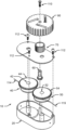
- FIG. 2 is an exploded trimetric view of the BSA of FIG. 1 ;
- FIG. 3 is a trimetric view of the housing of the BSA
- FIG. 4 is a trimetric view of the cover of the BSA
- FIG. 5 is an inverted trimetric view of the cover of the BSA
- FIG. 6 is a trimetric view of the drive gear of the BSA
- FIG. 7 is a trimetric view of the adjustment knob of the BSA, and
- FIG. 8 is an inverted trimetric view of the adjustment knob of the BS.
- a first embodiment of bidirectional spool apparatus (BSA) 10 comprises housing 20 , first geared spool 40 , second geared spool 50 , drive gear 60 , cover 70 , adjustment knob 90 , knob fastener 110 , a plurality of housing fasteners 112 , and cable 114 .
- Housing 20 preferably defines a plastic injection molded housing having floor 22 , wall 24 , a first cable access hole 26 , a second cable access hole 27 , raised land 28 , first spool spindle 30 , second spool spindle 32 , gear spindle 34 , and a plurality of fastening posts 36 .
- First geared spool 40 preferably defines a plastic injection molded spool having spindle hole 42 , and a plurality of gear teeth 44 .
- Second geared spool 50 preferably defines a plastic injection molded spool having spindle hole 52 , and a plurality of gear teeth 54 .
- Drive gear 60 preferably defines a plastic injection drive gear having a plurality of gear teeth 62 , and hexagonal shaped hex drive 64 .
- Cover 70 preferably defines a plastic injection molded cover having deck 72 , first spool hole 74 , second spool hole 76 , drive gear hole 78 , collar 80 , a plurality of collar teeth 82 , and a plurality of fastening holes 84 .
- Adjustment knob 90 preferably defines a plastic injection molded adjustment knob having a plurality of knurls 92 , collar 94 , hexagonal shaped hex drive 96 , a fastening hole 97 , a plurality of cam openings 98 , and a plurality of cams 100 , each cam 100 defining a flexible cantilevered flange cam, with each cam 100 having a cam tooth 102 .
- Knob fastener 110 , housing fasteners 112 preferably define conventional threaded fasteners.
- Cable 114 and cable 115 define conventional, preferably closed loop, cables such as cables that can secure a breath deflector (e.g. the breath deflector of US 20200179172), a shoe, or a boot.
- BSA 10 is assembled such that first geared spool 40 is rotatably positioned on first spool spindle 30 , second geared spool 50 is rotatably positioned on second spool spindle 32 , and drive gear 60 is rotatably positioned on gear spindle 34 .
- Cable 114 is wound around first geared spool 40 , passed through cable access hole 26 , and connected to an objected to be adjustably secured (e.g. the breath deflector of US 20200179172).
- Cable 115 is wound around second geared spool 50 , passed through cable access hole 27 , and connected to an objected to be adjustably secured (e.g. the breath deflector of US 20200179172).
- Cover 70 is then placed on housing 20 such that first spool spindle 30 is positioned within first spool hole 74 , second spool spindle 32 is positioned within second spool hole 76 , and drive gear 60 is positioned within drive gear hole 78 .
- Adjustment knob 90 is then rotatably positioned on cover 70 such that collar 94 is slidably positioned within collar 80 , hex drive 64 is engaged with hex drive 96 , and cam teeth 102 are meshed with collar teeth 82 .
- Fastener 110 is threaded through fastening hole 97 and into drive gear 60 such that drive gear 60 is secured to adjustment knob 90 such that rotation of adjustment knob 90 causes a corresponding rotation of drive gear 60 .
- Fasteners 112 are passed through fastening holes 84 and securingly threaded into fastening posts 36 .
- first geared spool 40 is in a drivable configuration and second geared spool 50 is in a freely rotatable (but for the friction of the apparatus) configuration.
- a user then rotates adjustment knob 90 .
- adjustment knob 90 causes first geared spool 40 to wind and tighten (reduce the payout of) cable 114 while allowing second geared spool 50 to rotate substantially freely and to allow cable 115 to loosen (increase the payout of), causing the object to be moved in a tightening direction.
- a user pulls adjustment knob 90 outward along the rotational axis of adjustment knob 90 causing teeth 62 of drive gear 60 to mesh with gear teeth 54 of second geared spool 50 and causing BSA 10 to enter a loosening mode.
- first geared spool 40 is in a freely rotatable (but for the friction of the apparatus) configuration and second geared spool 50 is in a drivable configuration.
- a user then rotates adjustment knob 90 .
- This rotation of adjustment knob 90 causes second geared spool 50 to wind and tighten (reduce the payout of) cable 115 while allowing first geared spool 40 to rotate substantially freely and to allow cable 114 to loosen (increase the payout of), causing the object to be moved in a loosening direction.
- cam teeth 102 of cams 100 sequentially flexingly engage and disengage collar teeth 82 providing for tactile feedback to a user who rotates adjustment knob 90 and causing adjustment knob 90 to remain in a fixed rotational adjustment position in the absence of a user applied rotational load on adjustment knob 90 .
Landscapes
- Footwear And Its Accessory, Manufacturing Method And Apparatuses (AREA)
Abstract
Disclosed is a bidirectional spool apparatus (BSA) and method of use. The BSA comprises a spool apparatus having a plurality of spools, a plurality of cables, and an adjustment knob. When the BSA is in a first mode, rotation of the adjustment knob causes a corresponding rotation of a first spool in a tightening direction and a tightening of a first cable but allows a second cable to rotate substantially freely, and such that when the BSA is in a second mode, rotation of the adjustment knob causes a corresponding rotation of a second spool in a tightening direction and a tightening of a second cable but allows a first cable to rotate substantially freely. Switching of the BSA from a first mode to a second mode and vice versa is accomplished by pulling the adjustment knob out a distance and by pushing the adjustment knob in a distance.
Description
This nonprovisional utility patent application is a continuation of and claims the benefit under 35 USC § 120 to allowed co-pending U.S. application Ser. No. 17/242,420 filed Apr. 28, 2021, which is incorporated herein in its entirety by this reference.
The present invention relates to spool apparatuses, and in particular, to spool apparatuses for use in tightening and loosening cables and like elongated drawing or securing members.
Various means are known in the art for securing tightening cables and like elongated drawing or securing members. However, such means are not heretofore known to have convenient bidirectional operation or to have a positive loosening ability. Examples of spool apparatuses are disclosed in the following list of US patents and applications, all of which are expressly incorporated herein by reference: 8,434,200 to Chen, U.S. Pat. No. 8,468,657 to Soderberg, U.S. Pat. No. 9,138,030 to Soderberg, U.S. Pat. No. 9,259,056 to Soderberg, U.S. Pat. No. 10,123,589 to Soderberg, U.S. Pat. No. 10,863,796 to Soderberg, 20100139057 to Soderberg, 20130014359 to Chen, 20130277485 to Soderberg, 20150101160 to Soderberg, 20160198803 to Soderberg, 20190069641 to Soderberg, 20200179172 to Johnson, and 20200390196 to Manzato.
The present invention is a bidirectional spool apparatus (BSA) and method of use. The BSA comprises a spool apparatus having a plurality of spools, a plurality of cables (or like elongated drawing or securing members), with each cable threaded or wound around a respective spool, and an adjustment knob. The BSA is adapted such that when in a first mode, rotation of the adjustment knob causes a corresponding rotation of a first spool in a tightening direction and a tightening (reduced payout) of a first cable but allows a second cable to rotate substantially freely (but for friction of the apparatus), and such that when in a second mode, rotation of the adjustment knob causes a corresponding rotation of a second spool in a tightening direction and a tightening (reduced payout) of a second cable but allows a first cable to rotate substantially freely (but for friction of the apparatus). The BSA is further adapted such that switching of the BSA from a first mode to a second mode and vice versa is accomplished by pulling the adjustment knob out a distance along the rotational axis of the adjustment knob and by pushing the adjustment knob in a distance along the rotational axis of the adjustment knob.
In order that the advantages of the invention will be readily understood, a more particular description of the invention briefly described above will be rendered by reference to specific embodiments that are illustrated in the appended drawings. Understanding that these drawings depict only typical embodiments of the invention and are not therefore to be considered to be limiting of its scope, the invention will be described and explained with additional specificity and detail through the use of the accompanying drawings, in which:
Reference throughout this specification to “one embodiment,” “an embodiment,” or similar language means that a particular feature, structure, or characteristic described in connection with the embodiment is included in at least one embodiment of the present invention. Thus, appearances of the phrases “in one embodiment,” “in an embodiment,” and similar language throughout this specification may, but do not necessarily, all refer to the same embodiment.
Furthermore, the described features, structures, or characteristics of the invention may be combined in any suitable manner in one or more embodiments. In the following description, numerous specific details are included to provide a thorough understanding of embodiments of the invention. One skilled in the relevant art will recognize, however, that the invention can be practiced without one or more of the specific details, or with other methods, components, materials, and so forth. In other instances, well-known structures, materials, or operations are not shown or described in detail to avoid obscuring aspects of the invention.
In order to facilitate the understanding of the present invention in reviewing the drawings accompanying the specification, a feature table is provided below. It is noted that like features are like numbered throughout all of the figures.
| FEATURE TABLE |
| # | | # | Feature | |
| 10 | |
20 | |
| 22 | |
24 | |
| 26 | First |
27 | Second |
| 28 | Raised |
||
| 30 | |
32 | |
| 34 | |
36 | Fastening |
| 40 | First geared |
42 | |
| 44 | |
50 | Second geared |
| 52 | |
54 | |
| 60 | |
62 | |
| 64 | Hex drive | 70 | |
| 72 | |
74 | |
| 76 | |
78 | |
| 80 | |
82 | |
| 84 | Fastening |
90 | |
| 92 | |
94 | Collar |
| 96 | |
98 | Cam opening |
| 100 | |
102 | |
| 110 | |
112 | |
| 114 | |
115 | Second cable |
Referring now to the drawings, a first embodiment of bidirectional spool apparatus (BSA) 10 comprises housing 20, first geared spool 40, second geared spool 50, drive gear 60, cover 70, adjustment knob 90, knob fastener 110, a plurality of housing fasteners 112, and cable 114. Housing 20 preferably defines a plastic injection molded housing having floor 22, wall 24, a first cable access hole 26, a second cable access hole 27, raised land 28, first spool spindle 30, second spool spindle 32, gear spindle 34, and a plurality of fastening posts 36. First geared spool 40 preferably defines a plastic injection molded spool having spindle hole 42, and a plurality of gear teeth 44. Second geared spool 50 preferably defines a plastic injection molded spool having spindle hole 52, and a plurality of gear teeth 54. Drive gear 60 preferably defines a plastic injection drive gear having a plurality of gear teeth 62, and hexagonal shaped hex drive 64. Cover 70 preferably defines a plastic injection molded cover having deck 72, first spool hole 74, second spool hole 76, drive gear hole 78, collar 80, a plurality of collar teeth 82, and a plurality of fastening holes 84. Adjustment knob 90 preferably defines a plastic injection molded adjustment knob having a plurality of knurls 92, collar 94, hexagonal shaped hex drive 96, a fastening hole 97, a plurality of cam openings 98, and a plurality of cams 100, each cam 100 defining a flexible cantilevered flange cam, with each cam 100 having a cam tooth 102. Knob fastener 110, housing fasteners 112 preferably define conventional threaded fasteners. Cable 114 and cable 115 define conventional, preferably closed loop, cables such as cables that can secure a breath deflector (e.g. the breath deflector of US 20200179172), a shoe, or a boot.
BSA 10 is assembled such that first geared spool 40 is rotatably positioned on first spool spindle 30, second geared spool 50 is rotatably positioned on second spool spindle 32, and drive gear 60 is rotatably positioned on gear spindle 34. Cable 114 is wound around first geared spool 40, passed through cable access hole 26, and connected to an objected to be adjustably secured (e.g. the breath deflector of US 20200179172). Cable 115 is wound around second geared spool 50, passed through cable access hole 27, and connected to an objected to be adjustably secured (e.g. the breath deflector of US 20200179172). Cover 70 is then placed on housing 20 such that first spool spindle 30 is positioned within first spool hole 74, second spool spindle 32 is positioned within second spool hole 76, and drive gear 60 is positioned within drive gear hole 78. Adjustment knob 90 is then rotatably positioned on cover 70 such that collar 94 is slidably positioned within collar 80, hex drive 64 is engaged with hex drive 96, and cam teeth 102 are meshed with collar teeth 82. Fastener 110 is threaded through fastening hole 97 and into drive gear 60 such that drive gear 60 is secured to adjustment knob 90 such that rotation of adjustment knob 90 causes a corresponding rotation of drive gear 60. Fasteners 112 are passed through fastening holes 84 and securingly threaded into fastening posts 36.
In practice, in order to tighten the object (e.g. the breath deflector of US 20200179172), a user pushes adjustment knob 90 inward along the rotational axis of adjustment knob 90 causing teeth 62 of drive gear 60 to mesh with gear teeth 44 of first geared spool 40 and causing BSA 10 to enter a tightening mode. In the tightening mode, first geared spool 40 is in a drivable configuration and second geared spool 50 is in a freely rotatable (but for the friction of the apparatus) configuration. A user then rotates adjustment knob 90. The rotation of adjustment knob 90 causes first geared spool 40 to wind and tighten (reduce the payout of) cable 114 while allowing second geared spool 50 to rotate substantially freely and to allow cable 115 to loosen (increase the payout of), causing the object to be moved in a tightening direction. In order to loosen the object (e.g. the breath deflector of US 20200179172), a user pulls adjustment knob 90 outward along the rotational axis of adjustment knob 90 causing teeth 62 of drive gear 60 to mesh with gear teeth 54 of second geared spool 50 and causing BSA 10 to enter a loosening mode. In the loosening mode, first geared spool 40 is in a freely rotatable (but for the friction of the apparatus) configuration and second geared spool 50 is in a drivable configuration. A user then rotates adjustment knob 90. This rotation of adjustment knob 90 causes second geared spool 50 to wind and tighten (reduce the payout of) cable 115 while allowing first geared spool 40 to rotate substantially freely and to allow cable 114 to loosen (increase the payout of), causing the object to be moved in a loosening direction. It is noted that when adjustment knob 90 is rotated, cam teeth 102 of cams 100 sequentially flexingly engage and disengage collar teeth 82 providing for tactile feedback to a user who rotates adjustment knob 90 and causing adjustment knob 90 to remain in a fixed rotational adjustment position in the absence of a user applied rotational load on adjustment knob 90.
The present invention may be embodied in other specific forms without departing from its spirit or essential characteristics. The described embodiments are to be considered in all respects only as illustrative and not restrictive. The scope of the invention is, therefore, indicated by the appended claims rather than by the foregoing description. All changes which come within the meaning and range of equivalency of the claims are to be embraced within their scope.
Claims (20)
1. An adjustment apparatus comprising a housing, a plurality of spools, a plurality of tension members, and an adjustment device, wherein said spools are movably secured within said housing and each of said plurality of tension members are in contact with a spool and extend outside of said housing, and wherein said apparatus comprises at least one of an adjustment configuration adapted such that when said adjustment device is actuated, a first tension member is tightened and a second tension member is loosened, and an adjustment configuration adapted such that when said adjustment device is actuated, said second tension member is tightened and said first tension member is loosened.
2. The apparatus of claim 1 , wherein when said adjustment device is in a first configuration and actuated an article is adjusted to a tightened configuration and wherein when said adjustment device is in a second configuration and actuated said article is adjusted to a loosened configuration.
3. The apparatus of claim 1 , wherein when said adjustment device is in a second configuration and actuated, a positive loosening load is placed on an article.
4. The apparatus of claim 1 , wherein actuation of said adjustment device provides a tactile user feedback commensurate to a degree of actuation of said adjustment device.
5. The apparatus of claim 1 , wherein in the absence of a user applied actuation load on said adjustment device, at least one spool remains immobile.
6. The apparatus of claim 1 , wherein when said adjustment device is actuated, at least one of tightening and loosening is affected in at least one of a breath deflector, a garment, and a footwear.
7. The apparatus of claim 1 , wherein said adjustment device includes a plurality of flexible cantilevered cam arms.
8. The apparatus of claim 7 , wherein said plurality of flexible cantilevered cam arms are snappingly engaged into teeth extending from said housing.
9. A reel based apparatus for use in tightening and loosening an article comprising a housing, a plurality of spools, a plurality of tension members, and an adjustment device, wherein said plurality of spools are rotatably secured within said housing and each of said plurality of tension members are wound around a respective spool and extend outside of said housing, and wherein said apparatus comprises at least one of an adjustment configuration adapted such that when said adjustment device is actuated, a first tension member is tightened and a second tension member is loosened, and an adjustment configuration adapted such that when said adjustment device is actuated, said second tension member is tightened and said first tension member is loosened, and wherein actuation of said adjustment device provides a tactile user feedback commensurate to a degree of actuation of said adjustment device, and wherein in the absence of a user applied actuation load on said adjustment device, said at least one spool remains rotationally fixed.
10. The apparatus of claim 9 , wherein when said adjustment device is in a first configuration and actuated an article is adjusted to a tightened configuration and wherein when said adjustment device is in a second configuration and actuated said article is adjusted to a loosened configuration, and wherein when said adjustment device is in a second configuration and actuated, a positive loosening load is placed on said at least one tension member.
11. The apparatus of claim 9 , wherein when said adjustment device is actuated, at least one of tightening and loosening is affected in at least one of a breath deflector, a garment, and a footwear.
12. The apparatus of claim 9 , wherein said adjustment device includes a plurality of flexible cantilevered cam arms snappingly engaged into teeth extending from said housing.
13. A method of adjusting an article comprising providing an apparatus comprising a housing, a plurality of spools, a plurality of tension members, and an adjustment device, wherein said spools are movably secured within said housing and each of said plurality of tension members are in contact with a spool and extend outside of said housing, and wherein said apparatus comprises at least one of an adjustment configuration adapted such that when said adjustment device is actuated, a first tension member is tightened and a second tension member is loosened, and an adjustment configuration adapted such that when said adjustment device is actuated, said second tension member is tightened and said first tension member is loosened, and adjusting said adjustment device so as to affect at least one of tightening a first tension member while a second tension member is loosened and tightening a second tension member while a first tension member is loosened.
14. The method of claim 13 , wherein said method further includes at least one of causing said adjustment device to be extended and causing said adjustment device to be retracted.
15. The method of claim 13 , wherein when said adjustment device is in a first configuration and actuated said article is adjusted to a tightened configuration and wherein when said adjustment device is in a second configuration and actuated said article is adjusted to a loosened configuration.
16. The method of claim 13 , wherein when said adjustment device is in a second configuration and actuated, a positive loosening load is placed on said article.
17. The method of claim 13 , wherein actuation of said adjustment device provides a tactile user feedback commensurate to a degree of actuation of said adjustment device.
18. The method of claim 13 , wherein in the absence of a user applied actuation load on said adjustment device, at least one spool remains immobile.
19. The method of claim 13 , wherein when said adjustment device is actuated, at least one of tightening and loosening is affected in at least one of a breath deflector, a garment, and a footwear.
20. The method of claim 13 , wherein said adjustment device includes a plurality of flexible cantilevered cam arms snappingly engaged into teeth extending from said housing.
Priority Applications (1)
| Application Number | Priority Date | Filing Date | Title |
|---|---|---|---|
| US18/192,990 US11891270B1 (en) | 2021-04-28 | 2023-03-30 | Bidirectional spool apparatus and method of use |
Applications Claiming Priority (2)
| Application Number | Priority Date | Filing Date | Title |
|---|---|---|---|
| US17/242,420 US11643298B2 (en) | 2021-04-28 | 2021-04-28 | Bidirectional spool apparatus and method of use |
| US18/192,990 US11891270B1 (en) | 2021-04-28 | 2023-03-30 | Bidirectional spool apparatus and method of use |
Related Parent Applications (1)
| Application Number | Title | Priority Date | Filing Date |
|---|---|---|---|
| US17/242,420 Continuation US11643298B2 (en) | 2021-04-28 | 2021-04-28 | Bidirectional spool apparatus and method of use |
Publications (1)
| Publication Number | Publication Date |
|---|---|
| US11891270B1 true US11891270B1 (en) | 2024-02-06 |
Family
ID=77177099
Family Applications (2)
| Application Number | Title | Priority Date | Filing Date |
|---|---|---|---|
| US17/242,420 Active 2041-11-12 US11643298B2 (en) | 2021-04-28 | 2021-04-28 | Bidirectional spool apparatus and method of use |
| US18/192,990 Active US11891270B1 (en) | 2021-04-28 | 2023-03-30 | Bidirectional spool apparatus and method of use |
Family Applications Before (1)
| Application Number | Title | Priority Date | Filing Date |
|---|---|---|---|
| US17/242,420 Active 2041-11-12 US11643298B2 (en) | 2021-04-28 | 2021-04-28 | Bidirectional spool apparatus and method of use |
Country Status (1)
| Country | Link |
|---|---|
| US (2) | US11643298B2 (en) |
Families Citing this family (5)
| Publication number | Priority date | Publication date | Assignee | Title |
|---|---|---|---|---|
| CN109923053B (en) * | 2016-12-09 | 2021-05-28 | 安达满纳米奇精密宝石有限公司 | Coiler |
| US11446181B2 (en) * | 2019-02-22 | 2022-09-20 | Corey B. Johnson | Breath deflector and method of use |
| US12503056B2 (en) * | 2020-01-24 | 2025-12-23 | Mobren, Inc. | Locking cargo restraint with multiple retracting cables |
| US11643298B2 (en) * | 2021-04-28 | 2023-05-09 | Corey B. Johnson | Bidirectional spool apparatus and method of use |
| PL4181724T3 (en) * | 2021-09-24 | 2024-09-30 | C.E.S. Ileri Kompozit Ve Savunma Teknolojileri Sanayi Ve Ticaret Anonim Sirketi | HELMET RATCHET KNOB MECHANISM |
Citations (9)
| Publication number | Priority date | Publication date | Assignee | Title |
|---|---|---|---|---|
| US3876045A (en) | 1972-09-27 | 1975-04-08 | Otto H Knarreborg | Reel device for extension cord |
| US4506446A (en) | 1983-02-22 | 1985-03-26 | Rodger Mitchell | Tape measure having two tapes |
| US20100139057A1 (en) | 2008-11-21 | 2010-06-10 | Soderberg Mark S | Reel based lacing system |
| US20130014359A1 (en) | 2011-07-13 | 2013-01-17 | Chin-Chu Chen | Adjusting device for tightening or loosing laces and straps |
| US8365887B2 (en) | 2010-12-17 | 2013-02-05 | Fischer Consumer Electronics | Retraction apparatus |
| US8684295B2 (en) | 2009-01-09 | 2014-04-01 | Hidenobu Taketsuna | Cord reel |
| US20200179172A1 (en) | 2019-02-22 | 2020-06-11 | Corey B. Johnson | Breath Deflector and Method of Use |
| US20200390196A1 (en) | 2017-07-18 | 2020-12-17 | Boa Technology Inc. | Configurations for footwear employing reel based closure systems |
| US11643298B2 (en) * | 2021-04-28 | 2023-05-09 | Corey B. Johnson | Bidirectional spool apparatus and method of use |
-
2021
- 2021-04-28 US US17/242,420 patent/US11643298B2/en active Active
-
2023
- 2023-03-30 US US18/192,990 patent/US11891270B1/en active Active
Patent Citations (19)
| Publication number | Priority date | Publication date | Assignee | Title |
|---|---|---|---|---|
| US3876045A (en) | 1972-09-27 | 1975-04-08 | Otto H Knarreborg | Reel device for extension cord |
| US4506446A (en) | 1983-02-22 | 1985-03-26 | Rodger Mitchell | Tape measure having two tapes |
| US20160198803A1 (en) | 2008-11-21 | 2016-07-14 | Boa Technology, Inc. | Reel based lacing system |
| US20100139057A1 (en) | 2008-11-21 | 2010-06-10 | Soderberg Mark S | Reel based lacing system |
| US10863796B2 (en) | 2008-11-21 | 2020-12-15 | Boa Technology, Inc. | Reel based lacing system |
| US20190069641A1 (en) | 2008-11-21 | 2019-03-07 | Boa Technology, Inc. | Reel based lacing system |
| US10123589B2 (en) | 2008-11-21 | 2018-11-13 | Boa Technology, Inc. | Reel based lacing system |
| US8468657B2 (en) | 2008-11-21 | 2013-06-25 | Boa Technology, Inc. | Reel based lacing system |
| US20130277485A1 (en) | 2008-11-21 | 2013-10-24 | Boa Technology, Inc. | Reel based lacing system |
| US20150101160A1 (en) | 2008-11-21 | 2015-04-16 | Boa Technology Inc. | Reel based lacing system |
| US9138030B2 (en) | 2008-11-21 | 2015-09-22 | Boa Technology Inc. | Reel based lacing system |
| US9259056B2 (en) | 2008-11-21 | 2016-02-16 | Boa Technology, Inc. | Reel based lacing system |
| US8684295B2 (en) | 2009-01-09 | 2014-04-01 | Hidenobu Taketsuna | Cord reel |
| US8365887B2 (en) | 2010-12-17 | 2013-02-05 | Fischer Consumer Electronics | Retraction apparatus |
| US8434200B2 (en) | 2011-07-13 | 2013-05-07 | Chin-Chu Chen | Adjusting device for tightening or loosing laces and straps |
| US20130014359A1 (en) | 2011-07-13 | 2013-01-17 | Chin-Chu Chen | Adjusting device for tightening or loosing laces and straps |
| US20200390196A1 (en) | 2017-07-18 | 2020-12-17 | Boa Technology Inc. | Configurations for footwear employing reel based closure systems |
| US20200179172A1 (en) | 2019-02-22 | 2020-06-11 | Corey B. Johnson | Breath Deflector and Method of Use |
| US11643298B2 (en) * | 2021-04-28 | 2023-05-09 | Corey B. Johnson | Bidirectional spool apparatus and method of use |
Also Published As
| Publication number | Publication date |
|---|---|
| US11643298B2 (en) | 2023-05-09 |
| US20210245991A1 (en) | 2021-08-12 |
Similar Documents
| Publication | Publication Date | Title |
|---|---|---|
| US11891270B1 (en) | Bidirectional spool apparatus and method of use | |
| US8002012B2 (en) | Venetian blind | |
| EP0926960B1 (en) | Helmet with adjustable safety strap | |
| US6267711B1 (en) | Elastic cord exercise assembly | |
| EP3578069B1 (en) | Rope adjusting device and assembly | |
| US20240024723A1 (en) | Adjustable Resistance Exercise Machine | |
| US20070272787A1 (en) | Hose/cable reeler | |
| CN101128141A (en) | Drives for coverings of building openings | |
| US10900233B2 (en) | Skylight with manual closing feature | |
| US5605079A (en) | Torsion spring tensioning tool | |
| US7637853B2 (en) | Conditioning and exercising device | |
| US10796674B2 (en) | Drumhead tuning rim system and method of use | |
| US2992450A (en) | Sliding door closer | |
| DE102023113951A1 (en) | CORD TENSIONER | |
| US10869457B1 (en) | Ratcheted pipe and strap operating drive system for door mechanisms | |
| US6805333B2 (en) | Cable lasher | |
| JP2022521654A (en) | Resistance device | |
| US20220238086A1 (en) | Drumhead Tuning Rim System and Method of Use | |
| US5002003A (en) | Boat mooring device | |
| JPH10131611A (en) | Window opening/closing operating device | |
| US20200329638A1 (en) | Dual handle speed adjustment device and lawn mower using same | |
| CN217854420U (en) | Rotating assembly and fitness equipment with same | |
| CN223008555U (en) | An octagonal rope buckle | |
| CN222217290U (en) | Head-mounted braided belt retractable head circumference adjusting structure | |
| EP4424199B1 (en) | Lacing shoe with quick tensioning device |
Legal Events
| Date | Code | Title | Description |
|---|---|---|---|
| FEPP | Fee payment procedure |
Free format text: ENTITY STATUS SET TO UNDISCOUNTED (ORIGINAL EVENT CODE: BIG.); ENTITY STATUS OF PATENT OWNER: SMALL ENTITY |
|
| FEPP | Fee payment procedure |
Free format text: ENTITY STATUS SET TO SMALL (ORIGINAL EVENT CODE: SMAL); ENTITY STATUS OF PATENT OWNER: SMALL ENTITY |
|
| STCF | Information on status: patent grant |
Free format text: PATENTED CASE |