US11888170B2 - Clamping member and battery accommodating device - Google Patents
Clamping member and battery accommodating device Download PDFInfo
- Publication number
- US11888170B2 US11888170B2 US17/496,818 US202117496818A US11888170B2 US 11888170 B2 US11888170 B2 US 11888170B2 US 202117496818 A US202117496818 A US 202117496818A US 11888170 B2 US11888170 B2 US 11888170B2
- Authority
- US
- United States
- Prior art keywords
- battery
- elastic structure
- clamping member
- arm
- parts
- Prior art date
- Legal status (The legal status is an assumption and is not a legal conclusion. Google has not performed a legal analysis and makes no representation as to the accuracy of the status listed.)
- Active, expires
Links
Images


Classifications
-
- H—ELECTRICITY
- H01—ELECTRIC ELEMENTS
- H01M—PROCESSES OR MEANS, e.g. BATTERIES, FOR THE DIRECT CONVERSION OF CHEMICAL ENERGY INTO ELECTRICAL ENERGY
- H01M50/00—Constructional details or processes of manufacture of the non-active parts of electrochemical cells other than fuel cells, e.g. hybrid cells
- H01M50/20—Mountings; Secondary casings or frames; Racks, modules or packs; Suspension devices; Shock absorbers; Transport or carrying devices; Holders
- H01M50/244—Secondary casings; Racks; Suspension devices; Carrying devices; Holders characterised by their mounting method
-
- H—ELECTRICITY
- H01—ELECTRIC ELEMENTS
- H01M—PROCESSES OR MEANS, e.g. BATTERIES, FOR THE DIRECT CONVERSION OF CHEMICAL ENERGY INTO ELECTRICAL ENERGY
- H01M50/00—Constructional details or processes of manufacture of the non-active parts of electrochemical cells other than fuel cells, e.g. hybrid cells
- H01M50/20—Mountings; Secondary casings or frames; Racks, modules or packs; Suspension devices; Shock absorbers; Transport or carrying devices; Holders
- H01M50/202—Casings or frames around the primary casing of a single cell or a single battery
-
- H—ELECTRICITY
- H01—ELECTRIC ELEMENTS
- H01M—PROCESSES OR MEANS, e.g. BATTERIES, FOR THE DIRECT CONVERSION OF CHEMICAL ENERGY INTO ELECTRICAL ENERGY
- H01M50/00—Constructional details or processes of manufacture of the non-active parts of electrochemical cells other than fuel cells, e.g. hybrid cells
- H01M50/20—Mountings; Secondary casings or frames; Racks, modules or packs; Suspension devices; Shock absorbers; Transport or carrying devices; Holders
- H01M50/204—Racks, modules or packs for multiple batteries or multiple cells
- H01M50/207—Racks, modules or packs for multiple batteries or multiple cells characterised by their shape
- H01M50/209—Racks, modules or packs for multiple batteries or multiple cells characterised by their shape adapted for prismatic or rectangular cells
-
- H—ELECTRICITY
- H01—ELECTRIC ELEMENTS
- H01M—PROCESSES OR MEANS, e.g. BATTERIES, FOR THE DIRECT CONVERSION OF CHEMICAL ENERGY INTO ELECTRICAL ENERGY
- H01M50/00—Constructional details or processes of manufacture of the non-active parts of electrochemical cells other than fuel cells, e.g. hybrid cells
- H01M50/20—Mountings; Secondary casings or frames; Racks, modules or packs; Suspension devices; Shock absorbers; Transport or carrying devices; Holders
- H01M50/262—Mountings; Secondary casings or frames; Racks, modules or packs; Suspension devices; Shock absorbers; Transport or carrying devices; Holders with fastening means, e.g. locks
- H01M50/264—Mountings; Secondary casings or frames; Racks, modules or packs; Suspension devices; Shock absorbers; Transport or carrying devices; Holders with fastening means, e.g. locks for cells or batteries, e.g. straps, tie rods or peripheral frames
-
- H—ELECTRICITY
- H01—ELECTRIC ELEMENTS
- H01M—PROCESSES OR MEANS, e.g. BATTERIES, FOR THE DIRECT CONVERSION OF CHEMICAL ENERGY INTO ELECTRICAL ENERGY
- H01M50/00—Constructional details or processes of manufacture of the non-active parts of electrochemical cells other than fuel cells, e.g. hybrid cells
- H01M50/20—Mountings; Secondary casings or frames; Racks, modules or packs; Suspension devices; Shock absorbers; Transport or carrying devices; Holders
- H01M50/289—Mountings; Secondary casings or frames; Racks, modules or packs; Suspension devices; Shock absorbers; Transport or carrying devices; Holders characterised by spacing elements or positioning means within frames, racks or packs
- H01M50/291—Mountings; Secondary casings or frames; Racks, modules or packs; Suspension devices; Shock absorbers; Transport or carrying devices; Holders characterised by spacing elements or positioning means within frames, racks or packs characterised by their shape
-
- Y—GENERAL TAGGING OF NEW TECHNOLOGICAL DEVELOPMENTS; GENERAL TAGGING OF CROSS-SECTIONAL TECHNOLOGIES SPANNING OVER SEVERAL SECTIONS OF THE IPC; TECHNICAL SUBJECTS COVERED BY FORMER USPC CROSS-REFERENCE ART COLLECTIONS [XRACs] AND DIGESTS
- Y02—TECHNOLOGIES OR APPLICATIONS FOR MITIGATION OR ADAPTATION AGAINST CLIMATE CHANGE
- Y02E—REDUCTION OF GREENHOUSE GAS [GHG] EMISSIONS, RELATED TO ENERGY GENERATION, TRANSMISSION OR DISTRIBUTION
- Y02E60/00—Enabling technologies; Technologies with a potential or indirect contribution to GHG emissions mitigation
- Y02E60/10—Energy storage using batteries
Definitions
- the present disclosure relates to a clamping member and a battery accommodating device, and more particularly, to a clamping member that is easy to operate when being implemented in a battery accommodating device.
- Battery compartment of common electronic devices such as notebook computers, smart appliance control hub, smart phones, keyboards, mouse, etc. often is designed with a structure that makes removing battery a difficult task for users.
- the present disclosure provides a clamping member and a battery accommodating device to effectively improve on the issues associated with removing battery from battery compartment of conventional electronic devices.
- the present disclosure provides a clamping member for use in a battery accommodating device having an accommodating slot for accommodating at least one battery.
- the clamping member has two arm parts, two protruding parts, an elastic structure, and two first pivot structures.
- the two protruding parts are formed respectively by each of the two arm parts extending from one end toward one side.
- the elastic structure is connected to another end of each of the two arm parts. A portion of each of the two protruding parts faces toward the elastic structure.
- Each of the two protruding parts and the elastic structure hold one end of the battery.
- the two first pivot structures are respectively disposed on the two arm parts.
- the present disclosure provides a battery accommodating device for accommodating a battery.
- the battery accommodating device includes a clamping member, a body, and two second pivot structures.
- the clamping member has two arm parts, two protruding parts formed respectively by the two arm parts extending from one end toward one side, an elastic structure connected to another end of the two arm parts, and two first pivot structures respectively disposed on the two arm parts. A portion of each of the two protruding parts is configured to face toward the elastic structure.
- the two producing parts and the elastic structure together hold one end of the battery. When the two arm parts move toward each other due to an external force, the elastic structure deforms elastically.
- the body has an accommodating slot for accommodating the battery and an excess slot for accommodating the elastic structure.
- the excess slot is in spatial communication with the accommodating slot and is formed by a base part of the body receding inward.
- the two second pivot structures are disposed in the accommodating slot of the body and respectively connected to the two first pivot structures.
- the clamping member is rotatable relative to the body due to another external force.
- the clamping member and the battery accommodating device through pivotally connecting the clamping member and the body and the design of the elastic structure, the two arm parts, and the two protruding parts on the clamping member, the clamping member and the battery accommodating device provided by the present disclosure allow a user to remove the battery from the accommodating slot by simply pushing the two protruding parts to rotate the clamping member relative to the body, which causes the elastic structure to push up the battery, and thus the battery is disengaged from the accommodating slot and can be easily taken out by the user.
- FIG. 1 is a perspective view of a battery accommodating device according to an embodiment of the present disclosure
- FIG. 2 is a perspective view of a battery accommodating device viewing from a different angle according to an embodiment of the present disclosure
- FIG. 3 is an exploded perspective view showing a body and a clamping member of a battery accommodating device according to an embodiment of the present disclosure
- FIG. 4 is a top view of a battery accommodating device according to an embodiment of the present disclosure.
- FIG. 5 is a fragmentary cross-sectional view of a battery accommodating device according to an embodiment of the present disclosure
- FIG. 6 is a perspective view of a clamping member according to an embodiment of the present disclosure.
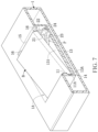
- FIG. 7 is a fragmentary cross-sectional perspective view showing a battery being placed in a battery accommodating device according to an embodiment of the present disclosure
- FIG. 8 is a fragmentary cross-sectional view showing a battery being placed in a battery accommodating device according to an embodiment of the present disclosure
- FIG. 9 is a fragmentary cross-sectional perspective view showing a battery being clamped in a battery accommodating device according to an embodiment of the present disclosure.
- FIG. 10 is a fragmentary cross-sectional view showing a battery being in a battery accommodating device according to an embodiment of the present disclosure
- FIG. 11 is a cross-sectional view showing a battery engaged in a battery accommodating device according to an embodiment of the present disclosure
- FIG. 12 is a side view of a clamping member according to an embodiment of the present disclosure.
- FIG. 13 is a perspective view of a clamping member according to another embodiment of the present disclosure.
- Numbering terms such as “first”, “second” or “third” can be used to describe various components, signals or the like, which are for distinguishing one component/signal from another one only, and are not intended to, nor should be construed to impose any substantive limitations on the components, signals or the like.
- an embodiment of the present disclosure provides a battery accommodating device 100 for accommodating a battery B.
- the battery accommodating device 100 includes a body 1 and a clamping member 2 .
- the battery accommodating device 100 may be implemented in all sorts of electronic devices, and the body 1 of the battery accommodating device 100 may be a portion of the electronic device.
- the body 1 could be a portion of a housing of the electronic device, wherein the electronic device can be any electronic device with a battery, such as a notebook computer, a smart appliance control hub, a keyboard, a mouse, a smart phone, a smart tablet computer, etc.
- the body 1 has an accommodating slot 1 A, two retaining structures 11 , an excess slot 1 B, and two second pivot structures 12 .
- the accommodating slot 1 A is used to accommodate the battery B.
- the excess slot 1 B is formed by a base part 13 of the body 1 receding inward and is in spatial communication with the accommodating slot 1 A. Since the main purpose of the accommodating slot 1 A is to accommodate the battery B, the shape and size of the accommodating slot 1 A vary according to the shape and size of the battery B, and it is to be noted that the embodiment shown in the figure is for exemplary purpose only.
- the excess slot 1 B is used to accommodate a portion of the clamping member 2 , and so the shape and configuration of the excess slot 1 B are determined by and in corresponding to the shape and configuration of the clamping member 2 in the body 1 .
- the two retaining structures 11 are disposed in the body 1 and located at one end of the accommodating slot 1 A. Each retaining structure 11 and the base part 13 together form a retaining notch 11 A for accommodating one end of the battery B, and the two retaining notches 11 A and the base part 13 , together, hold one end of the battery B.
- the two retaining structures 11 are formed on a side wall 14 of the body 1 and are spaced apart, but the configuration of the two retaining structures 11 in the body 1 is not limited thereto.
- the scope of the retaining structure 11 includes any configuration that can be used to constrain one end of the battery B, and therefore the retaining structure 11 is not limited in number, configuration, or size by the embodiments shown in the present disclosure.
- the base part 13 of the body 1 can be dented inwardly to form two recesses 13 A respectively located below the two retaining structures 11 , so users can place one end of the battery B between the two retaining structures 11 and the base part 13 of the body 1 more easily.
- FIG. 7 through the design of the two recesses 13 A, during the process of disposing one end of the battery B between the retaining structures 11 and the base part 13 , a portion of the battery B is correspondingly in the recesses 13 A, such that one end of the battery B is disposed in the retaining notches 11 A between the two retaining structures 11 and the base part 13 more easily.
- the two recesses 13 A are located at two corners of the base part 13 , but the present disclosure is not limited thereby. In other embodiments, the two recesses 13 A can be connected to form a single recess 13 A, and each recess 13 A is not limited in size and shape by the embodiments shown in the present disclosure.
- the two second pivot structures 12 are disposed on the body 1 and located in the accommodating slot 1 A.
- the two second pivot structures 12 are disposed at the other end of the accommodating slot 1 A opposite to the end of the accommodating slot 1 A with the two retaining structures 11 .
- the two second pivot structures 12 are used to pivotally connect with two first pivot structures 24 of the clamping member 2 .
- each of the two second pivot structures 12 is a cylindrical structure, but the shape of the second pivot structures 12 is not limited thereby.
- each of the two second pivot structures 12 can be a cavity, a through hole, or a semi-sphere protrusion.
- the clamping member 2 is detachably fastened in the body 1 and includes two arm parts 21 , two protruding parts 22 , an elastic structure 23 , and two first pivot structures 24 .
- Each of the two arm parts 21 extends from one end toward one side to form one protruding part 22 .
- the size and shape of each arm part 21 vary according to demand, and the embodiments shown in the present disclosure are for exemplary purpose only.
- the elastic structure 23 is connected to the other end of each of the two arm parts 21 .
- a portion of each of the two protruding parts 22 is configured to face toward the elastic structure 23 .
- each arm part 21 is of a rectangular structure having a wide side surface 211 .
- Two ends of the elastic structure 23 are connected respectively to the wide side surface 211 of the two arm parts 21 , and each protruding part 22 is formed on the same wide side surface 211 of each arm part 21 .
- the elastic structure 23 is capable to deform elastically when applied with an external force, and the elastically deformed elastic structure 23 can restore/return to its original state when the external force is no longer applied to the elastic structure 23 .
- Each arm part 21 is disposed with one first pivot structure 24 .
- Each first pivot structure 24 is used to pivotally connect with one second pivot structure 12 , and the clamping member is rotatable relative to the body 1 through the pivotally-connected first pivot structures 24 and second pivot structures 12 .
- each first pivot structure 24 is a through hole while each second pivot structure 12 is a corresponding cylindrical structure, but the shape and size of each first pivot structure 24 and of each second pivot structure 12 is not limited thereby.
- each first pivot structure 24 can be a cylindrical structure while each second pivot structure 12 is a corresponding through hole.
- the design of the elastic structure 23 makes the two first pivot structures 24 of the clamping member 2 to be more easily engaged with the two second pivot structures 12 of the body 1 when the clamping member 2 is being installed in the accommodating slot 1 A.
- the user holds the outer sides of the two protruding parts 22 and squeezes the two arm parts 21 to make the elastic structure 23 that is connected to the two arm parts 21 deform elastically and the distance between the two arm parts 21 shortened.
- the user is able to, in a relatively easier manner, dispose the clamping member 2 in the accommodating slot 1 A and engage the two first pivot structures 24 with the two second pivot structures 12 .
- the width of the accommodating slot 1 A is slightly smaller than the width of the clamping 2 when the clamping 2 is not squeezed, so that the elastic structure 23 is slightly compressed by the body 1 when the two first pivot structures 24 of the clamping member 2 are pivotally connected with the two second pivot structures 12 of the body 1 , wherein the elastic resilience of the elastic structure 23 enforces each first pivot structure 12 to better connect with the corresponding second pivot structure 24 .
- the user can remove the clamping member 2 from the accommodating slot 1 A by squeezing the two arm parts 21 , which makes the two arm parts move toward each other, to disengage the pivot connections between the two first pivot structures 24 and the two second pivot structures 12 .
- the clamping member 2 can be removed easily from the accommodating slot 1 A.
- each protruding part 22 has an inclined surface 221 on the side that is away from the elastic structure 23 .
- a clamping notch 2 A is formed by a portion of one protruding part 22 , one arm part 21 , and a portion of the elastic structure 23 , and the two clamping notches 2 A of the clamping member 2 are used to hold one end or one portion of the battery B.
- the height of each clamping notch 2 A as shown in FIG. 8 is between 0.5 mm to 1.5 mm, but the height 2 AH of the clamping notches 2 A is not limited thereto and can vary according to the thickness of the battery B.
- the user can compress the battery B and move the battery B toward the base part 13 , during which the battery B moves along the two inclined surfaces 221 and pushes the clamping member 2 to rotate relative to the body 1 before gradually entering the two clamping notches 2 A formed by the two protruding parts 22 , the two arm parts 21 , and the elastic structure 23 .
- the body 1 further includes two block structures 16 connected to the body 1 and located in the accommodating slot 1 A adjacent to the two arm parts 21 .
- the clamping member 2 is rotated relative to the accommodating slot 1 A to a predetermined angle due to an external force, the two arm parts 21 lean against the two block structures 16 , and the two block structures 16 are used to restrict the rotating angle of the clamping member 2 relative to the accommodating slot 1 A.
- the horizontal distance W between each arm part 21 and each block structure 16 is between 2 mm to 5 mm, so it would be easier for the user to put fingers through the gap S and reach the bottom of the battery B.
- the first distance D 1 is 0.25 to 4 times the second distance D 2 .
- the vertical distance between the center of each first pivot structure 24 and one end of the arm part 21 to which is connected is defined as a first vertical distance H 1 and the vertical distance between the center of each first pivot structure 24 and the other end of the arm part 21 to which is connected is defined as a second vertical distance H 2
- the first vertical distance H 1 is 1.5 to 4.5 times the second vertical distance H 2 .
- An included angle ⁇ between the inclined surface 221 of each protruding part 22 and a horizontal plane is between 45 degrees to 55 degrees.
- the clamping member is of another embodiment, and the major difference is that the elastic structure 23 A of the clamping member 2 is not an arched structure but a W-shaped structure.
- the shape of the elastic structure 23 A is not limited by this or previous embodiments. Any elastic structure 23 A that elastically deforms when the outer sides of the two arm parts 21 are squeezed is applicable to the clamping member 2 .
- clamping member 2 of the present disclosure may be manufactured, sold, or practiced solely and not limited to being manufacture, sold, or practiced together with the body.
- the clamping member can allow the user to place the battery in the accommodating slot and take the battery out of the accommodating slot easily and without using other tools.
Landscapes
- Chemical & Material Sciences (AREA)
- Chemical Kinetics & Catalysis (AREA)
- Electrochemistry (AREA)
- General Chemical & Material Sciences (AREA)
- Battery Mounting, Suspending (AREA)
Abstract
Description
Claims (15)
Applications Claiming Priority (2)
| Application Number | Priority Date | Filing Date | Title |
|---|---|---|---|
| TW110120325 | 2021-06-04 | ||
| TW110120325A TWI784554B (en) | 2021-06-04 | 2021-06-04 | Clamping member and battery accommodating device |
Publications (2)
| Publication Number | Publication Date |
|---|---|
| US20220393288A1 US20220393288A1 (en) | 2022-12-08 |
| US11888170B2 true US11888170B2 (en) | 2024-01-30 |
Family
ID=84284417
Family Applications (1)
| Application Number | Title | Priority Date | Filing Date |
|---|---|---|---|
| US17/496,818 Active 2042-07-16 US11888170B2 (en) | 2021-06-04 | 2021-10-08 | Clamping member and battery accommodating device |
Country Status (2)
| Country | Link |
|---|---|
| US (1) | US11888170B2 (en) |
| TW (1) | TWI784554B (en) |
Citations (2)
| Publication number | Priority date | Publication date | Assignee | Title |
|---|---|---|---|---|
| TWI540411B (en) | 2015-02-04 | 2016-07-01 | 緯創資通股份有限公司 | Electronic device and battery accommodating module |
| CN208608395U (en) * | 2018-09-06 | 2019-03-15 | 天津百盛高通电气设备有限公司 | A kind of anticreep battery wire folder |
Family Cites Families (1)
| Publication number | Priority date | Publication date | Assignee | Title |
|---|---|---|---|---|
| JP6705708B2 (en) * | 2016-06-30 | 2020-06-03 | 株式会社シマノ | Battery holder, battery unit, and battery component including them |
-
2021
- 2021-06-04 TW TW110120325A patent/TWI784554B/en active
- 2021-10-08 US US17/496,818 patent/US11888170B2/en active Active
Patent Citations (3)
| Publication number | Priority date | Publication date | Assignee | Title |
|---|---|---|---|---|
| TWI540411B (en) | 2015-02-04 | 2016-07-01 | 緯創資通股份有限公司 | Electronic device and battery accommodating module |
| US20160226037A1 (en) | 2015-02-04 | 2016-08-04 | Wistron Corporation | Electronic device and battery accommodating module |
| CN208608395U (en) * | 2018-09-06 | 2019-03-15 | 天津百盛高通电气设备有限公司 | A kind of anticreep battery wire folder |
Non-Patent Citations (1)
| Title |
|---|
| Li, An Anti-dropping Battery Wiring Clip, Mar. 2019, See the Abstract. (Year: 2019). * |
Also Published As
| Publication number | Publication date |
|---|---|
| TW202249563A (en) | 2022-12-16 |
| TWI784554B (en) | 2022-11-21 |
| US20220393288A1 (en) | 2022-12-08 |
Similar Documents
| Publication | Publication Date | Title |
|---|---|---|
| US9176546B2 (en) | Hard disk assembly | |
| US20090123220A1 (en) | Fixture for engaging with a male screw | |
| US9047056B2 (en) | Protective casing having keyboard | |
| US9831477B2 (en) | Electronic device and battery accommodating module | |
| US7914919B2 (en) | Battery fastening assembly | |
| US20100320221A1 (en) | Cover assembly | |
| CN108551013B (en) | Deck component and electronic equipment | |
| US20110183175A1 (en) | Fixing mechanism and electronic device using the same | |
| US8349480B1 (en) | Electronic device with detachable battery | |
| US9405334B2 (en) | Electronic card holder and electronic device using same | |
| US11888170B2 (en) | Clamping member and battery accommodating device | |
| US9239592B1 (en) | Docking station | |
| US20060290686A1 (en) | Input pen | |
| CN205044309U (en) | Ink horn that fastening is decided ink horn and is connected with ink horn portion of keeping | |
| US9106084B2 (en) | Electrical charger for charging electronic device | |
| TWM554631U (en) | Positioning device of storage unit | |
| US8848393B2 (en) | Electronic apparatus, positioning element and electronic device fixing module | |
| US20150029647A1 (en) | Electronic device | |
| US20130105422A1 (en) | Fixing device for data storage device | |
| US8107237B2 (en) | Electronic device with latching assembly | |
| US7841874B2 (en) | Socket protector | |
| CN115498350B (en) | Engaging member and battery accommodating device | |
| CN107665010B (en) | Connecting seat | |
| US9011166B2 (en) | Electronic device and connector module | |
| TWI782759B (en) | Portable electronic device |
Legal Events
| Date | Code | Title | Description |
|---|---|---|---|
| AS | Assignment |
Owner name: WISTRON NEWEB CORPORATION, TAIWAN Free format text: ASSIGNMENT OF ASSIGNORS INTEREST;ASSIGNORS:CHEN, YAN-DA;LU, YING-YEN;REEL/FRAME:057737/0004 Effective date: 20211007 |
|
| FEPP | Fee payment procedure |
Free format text: ENTITY STATUS SET TO UNDISCOUNTED (ORIGINAL EVENT CODE: BIG.); ENTITY STATUS OF PATENT OWNER: LARGE ENTITY |
|
| STPP | Information on status: patent application and granting procedure in general |
Free format text: DOCKETED NEW CASE - READY FOR EXAMINATION |
|
| STPP | Information on status: patent application and granting procedure in general |
Free format text: NON FINAL ACTION MAILED |
|
| STPP | Information on status: patent application and granting procedure in general |
Free format text: RESPONSE TO NON-FINAL OFFICE ACTION ENTERED AND FORWARDED TO EXAMINER |
|
| STPP | Information on status: patent application and granting procedure in general |
Free format text: NOTICE OF ALLOWANCE MAILED -- APPLICATION RECEIVED IN OFFICE OF PUBLICATIONS |
|
| STPP | Information on status: patent application and granting procedure in general |
Free format text: PUBLICATIONS -- ISSUE FEE PAYMENT VERIFIED |
|
| STCF | Information on status: patent grant |
Free format text: PATENTED CASE |
|
| AS | Assignment |
Owner name: WNC CORPORATION, TAIWAN Free format text: CHANGE OF NAME;ASSIGNOR:WISTRON NEWEB CORPORATION;REEL/FRAME:072255/0226 Effective date: 20250521 |