US11879608B2 - Automotive lamp optical element, automotive lamp module, and vehicle - Google Patents
Automotive lamp optical element, automotive lamp module, and vehicle Download PDFInfo
- Publication number
- US11879608B2 US11879608B2 US17/596,008 US202017596008A US11879608B2 US 11879608 B2 US11879608 B2 US 11879608B2 US 202017596008 A US202017596008 A US 202017596008A US 11879608 B2 US11879608 B2 US 11879608B2
- Authority
- US
- United States
- Prior art keywords
- light
- incident
- automotive lamp
- transmission
- optical element
- Prior art date
- Legal status (The legal status is an assumption and is not a legal conclusion. Google has not performed a legal analysis and makes no representation as to the accuracy of the status listed.)
- Active, expires
Links
- 230000003287 optical effect Effects 0.000 title claims abstract description 108
- 230000005540 biological transmission Effects 0.000 claims abstract description 101
- 230000007423 decrease Effects 0.000 claims description 2
- 239000003973 paint Substances 0.000 description 8
- 238000004519 manufacturing process Methods 0.000 description 6
- 238000009434 installation Methods 0.000 description 5
- 239000011159 matrix material Substances 0.000 description 5
- 238000005286 illumination Methods 0.000 description 4
- 230000035699 permeability Effects 0.000 description 3
- VYPSYNLAJGMNEJ-UHFFFAOYSA-N Silicium dioxide Chemical compound O=[Si]=O VYPSYNLAJGMNEJ-UHFFFAOYSA-N 0.000 description 2
- 238000000034 method Methods 0.000 description 2
- 229920003023 plastic Polymers 0.000 description 2
- 229920003229 poly(methyl methacrylate) Polymers 0.000 description 2
- 239000004926 polymethyl methacrylate Substances 0.000 description 2
- 230000004313 glare Effects 0.000 description 1
- 239000011521 glass Substances 0.000 description 1
- 238000011900 installation process Methods 0.000 description 1
- 239000000463 material Substances 0.000 description 1
- 238000010422 painting Methods 0.000 description 1
- 239000004033 plastic Substances 0.000 description 1
- 239000004417 polycarbonate Substances 0.000 description 1
- 229920000515 polycarbonate Polymers 0.000 description 1
- 239000000741 silica gel Substances 0.000 description 1
- 229910002027 silica gel Inorganic materials 0.000 description 1
Images


Classifications
-
- F—MECHANICAL ENGINEERING; LIGHTING; HEATING; WEAPONS; BLASTING
- F21—LIGHTING
- F21S—NON-PORTABLE LIGHTING DEVICES; SYSTEMS THEREOF; VEHICLE LIGHTING DEVICES SPECIALLY ADAPTED FOR VEHICLE EXTERIORS
- F21S41/00—Illuminating devices specially adapted for vehicle exteriors, e.g. headlamps
- F21S41/10—Illuminating devices specially adapted for vehicle exteriors, e.g. headlamps characterised by the light source
- F21S41/19—Attachment of light sources or lamp holders
- F21S41/192—Details of lamp holders, terminals or connectors
-
- F—MECHANICAL ENGINEERING; LIGHTING; HEATING; WEAPONS; BLASTING
- F21—LIGHTING
- F21S—NON-PORTABLE LIGHTING DEVICES; SYSTEMS THEREOF; VEHICLE LIGHTING DEVICES SPECIALLY ADAPTED FOR VEHICLE EXTERIORS
- F21S41/00—Illuminating devices specially adapted for vehicle exteriors, e.g. headlamps
-
- B—PERFORMING OPERATIONS; TRANSPORTING
- B60—VEHICLES IN GENERAL
- B60Q—ARRANGEMENT OF SIGNALLING OR LIGHTING DEVICES, THE MOUNTING OR SUPPORTING THEREOF OR CIRCUITS THEREFOR, FOR VEHICLES IN GENERAL
- B60Q1/00—Arrangement of optical signalling or lighting devices, the mounting or supporting thereof or circuits therefor
- B60Q1/02—Arrangement of optical signalling or lighting devices, the mounting or supporting thereof or circuits therefor the devices being primarily intended to illuminate the way ahead or to illuminate other areas of way or environments
- B60Q1/04—Arrangement of optical signalling or lighting devices, the mounting or supporting thereof or circuits therefor the devices being primarily intended to illuminate the way ahead or to illuminate other areas of way or environments the devices being headlights
- B60Q1/0408—Arrangement of optical signalling or lighting devices, the mounting or supporting thereof or circuits therefor the devices being primarily intended to illuminate the way ahead or to illuminate other areas of way or environments the devices being headlights built into the vehicle body, e.g. details concerning the mounting of the headlamps on the vehicle body
-
- B—PERFORMING OPERATIONS; TRANSPORTING
- B60—VEHICLES IN GENERAL
- B60Q—ARRANGEMENT OF SIGNALLING OR LIGHTING DEVICES, THE MOUNTING OR SUPPORTING THEREOF OR CIRCUITS THEREFOR, FOR VEHICLES IN GENERAL
- B60Q1/00—Arrangement of optical signalling or lighting devices, the mounting or supporting thereof or circuits therefor
- B60Q1/02—Arrangement of optical signalling or lighting devices, the mounting or supporting thereof or circuits therefor the devices being primarily intended to illuminate the way ahead or to illuminate other areas of way or environments
- B60Q1/04—Arrangement of optical signalling or lighting devices, the mounting or supporting thereof or circuits therefor the devices being primarily intended to illuminate the way ahead or to illuminate other areas of way or environments the devices being headlights
- B60Q1/06—Arrangement of optical signalling or lighting devices, the mounting or supporting thereof or circuits therefor the devices being primarily intended to illuminate the way ahead or to illuminate other areas of way or environments the devices being headlights adjustable, e.g. remotely-controlled from inside vehicle
- B60Q1/068—Arrangement of optical signalling or lighting devices, the mounting or supporting thereof or circuits therefor the devices being primarily intended to illuminate the way ahead or to illuminate other areas of way or environments the devices being headlights adjustable, e.g. remotely-controlled from inside vehicle by mechanical means
- B60Q1/0683—Adjustable by rotation of a screw
- B60Q1/0686—Adjustable by rotation of a screw using a position indicator mounted on the headlight and permanently attached thereto
-
- B—PERFORMING OPERATIONS; TRANSPORTING
- B60—VEHICLES IN GENERAL
- B60Q—ARRANGEMENT OF SIGNALLING OR LIGHTING DEVICES, THE MOUNTING OR SUPPORTING THEREOF OR CIRCUITS THEREFOR, FOR VEHICLES IN GENERAL
- B60Q1/00—Arrangement of optical signalling or lighting devices, the mounting or supporting thereof or circuits therefor
- B60Q1/02—Arrangement of optical signalling or lighting devices, the mounting or supporting thereof or circuits therefor the devices being primarily intended to illuminate the way ahead or to illuminate other areas of way or environments
- B60Q1/04—Arrangement of optical signalling or lighting devices, the mounting or supporting thereof or circuits therefor the devices being primarily intended to illuminate the way ahead or to illuminate other areas of way or environments the devices being headlights
- B60Q1/14—Arrangement of optical signalling or lighting devices, the mounting or supporting thereof or circuits therefor the devices being primarily intended to illuminate the way ahead or to illuminate other areas of way or environments the devices being headlights having dimming means
- B60Q1/1415—Dimming circuits
- B60Q1/1423—Automatic dimming circuits, i.e. switching between high beam and low beam due to change of ambient light or light level in road traffic
-
- F—MECHANICAL ENGINEERING; LIGHTING; HEATING; WEAPONS; BLASTING
- F21—LIGHTING
- F21S—NON-PORTABLE LIGHTING DEVICES; SYSTEMS THEREOF; VEHICLE LIGHTING DEVICES SPECIALLY ADAPTED FOR VEHICLE EXTERIORS
- F21S41/00—Illuminating devices specially adapted for vehicle exteriors, e.g. headlamps
- F21S41/10—Illuminating devices specially adapted for vehicle exteriors, e.g. headlamps characterised by the light source
- F21S41/14—Illuminating devices specially adapted for vehicle exteriors, e.g. headlamps characterised by the light source characterised by the type of light source
- F21S41/141—Light emitting diodes [LED]
- F21S41/143—Light emitting diodes [LED] the main emission direction of the LED being parallel to the optical axis of the illuminating device
-
- F—MECHANICAL ENGINEERING; LIGHTING; HEATING; WEAPONS; BLASTING
- F21—LIGHTING
- F21S—NON-PORTABLE LIGHTING DEVICES; SYSTEMS THEREOF; VEHICLE LIGHTING DEVICES SPECIALLY ADAPTED FOR VEHICLE EXTERIORS
- F21S41/00—Illuminating devices specially adapted for vehicle exteriors, e.g. headlamps
- F21S41/10—Illuminating devices specially adapted for vehicle exteriors, e.g. headlamps characterised by the light source
- F21S41/14—Illuminating devices specially adapted for vehicle exteriors, e.g. headlamps characterised by the light source characterised by the type of light source
- F21S41/141—Light emitting diodes [LED]
- F21S41/151—Light emitting diodes [LED] arranged in one or more lines
- F21S41/153—Light emitting diodes [LED] arranged in one or more lines arranged in a matrix
-
- F—MECHANICAL ENGINEERING; LIGHTING; HEATING; WEAPONS; BLASTING
- F21—LIGHTING
- F21S—NON-PORTABLE LIGHTING DEVICES; SYSTEMS THEREOF; VEHICLE LIGHTING DEVICES SPECIALLY ADAPTED FOR VEHICLE EXTERIORS
- F21S41/00—Illuminating devices specially adapted for vehicle exteriors, e.g. headlamps
- F21S41/20—Illuminating devices specially adapted for vehicle exteriors, e.g. headlamps characterised by refractors, transparent cover plates, light guides or filters
- F21S41/24—Light guides
-
- F—MECHANICAL ENGINEERING; LIGHTING; HEATING; WEAPONS; BLASTING
- F21—LIGHTING
- F21S—NON-PORTABLE LIGHTING DEVICES; SYSTEMS THEREOF; VEHICLE LIGHTING DEVICES SPECIALLY ADAPTED FOR VEHICLE EXTERIORS
- F21S41/00—Illuminating devices specially adapted for vehicle exteriors, e.g. headlamps
- F21S41/20—Illuminating devices specially adapted for vehicle exteriors, e.g. headlamps characterised by refractors, transparent cover plates, light guides or filters
- F21S41/25—Projection lenses
- F21S41/27—Thick lenses
-
- F—MECHANICAL ENGINEERING; LIGHTING; HEATING; WEAPONS; BLASTING
- F21—LIGHTING
- F21S—NON-PORTABLE LIGHTING DEVICES; SYSTEMS THEREOF; VEHICLE LIGHTING DEVICES SPECIALLY ADAPTED FOR VEHICLE EXTERIORS
- F21S41/00—Illuminating devices specially adapted for vehicle exteriors, e.g. headlamps
- F21S41/20—Illuminating devices specially adapted for vehicle exteriors, e.g. headlamps characterised by refractors, transparent cover plates, light guides or filters
- F21S41/29—Attachment thereof
- F21S41/295—Attachment thereof specially adapted to projection lenses
-
- F—MECHANICAL ENGINEERING; LIGHTING; HEATING; WEAPONS; BLASTING
- F21—LIGHTING
- F21S—NON-PORTABLE LIGHTING DEVICES; SYSTEMS THEREOF; VEHICLE LIGHTING DEVICES SPECIALLY ADAPTED FOR VEHICLE EXTERIORS
- F21S41/00—Illuminating devices specially adapted for vehicle exteriors, e.g. headlamps
- F21S41/30—Illuminating devices specially adapted for vehicle exteriors, e.g. headlamps characterised by reflectors
- F21S41/32—Optical layout thereof
- F21S41/322—Optical layout thereof the reflector using total internal reflection
-
- F—MECHANICAL ENGINEERING; LIGHTING; HEATING; WEAPONS; BLASTING
- F21—LIGHTING
- F21S—NON-PORTABLE LIGHTING DEVICES; SYSTEMS THEREOF; VEHICLE LIGHTING DEVICES SPECIALLY ADAPTED FOR VEHICLE EXTERIORS
- F21S41/00—Illuminating devices specially adapted for vehicle exteriors, e.g. headlamps
- F21S41/30—Illuminating devices specially adapted for vehicle exteriors, e.g. headlamps characterised by reflectors
- F21S41/37—Illuminating devices specially adapted for vehicle exteriors, e.g. headlamps characterised by reflectors characterised by their material, surface treatment or coatings
-
- F—MECHANICAL ENGINEERING; LIGHTING; HEATING; WEAPONS; BLASTING
- F21—LIGHTING
- F21S—NON-PORTABLE LIGHTING DEVICES; SYSTEMS THEREOF; VEHICLE LIGHTING DEVICES SPECIALLY ADAPTED FOR VEHICLE EXTERIORS
- F21S41/00—Illuminating devices specially adapted for vehicle exteriors, e.g. headlamps
- F21S41/40—Illuminating devices specially adapted for vehicle exteriors, e.g. headlamps characterised by screens, non-reflecting members, light-shielding members or fixed shades
- F21S41/43—Illuminating devices specially adapted for vehicle exteriors, e.g. headlamps characterised by screens, non-reflecting members, light-shielding members or fixed shades characterised by the shape thereof
-
- F—MECHANICAL ENGINEERING; LIGHTING; HEATING; WEAPONS; BLASTING
- F21—LIGHTING
- F21S—NON-PORTABLE LIGHTING DEVICES; SYSTEMS THEREOF; VEHICLE LIGHTING DEVICES SPECIALLY ADAPTED FOR VEHICLE EXTERIORS
- F21S41/00—Illuminating devices specially adapted for vehicle exteriors, e.g. headlamps
- F21S41/40—Illuminating devices specially adapted for vehicle exteriors, e.g. headlamps characterised by screens, non-reflecting members, light-shielding members or fixed shades
- F21S41/47—Attachment thereof
-
- F—MECHANICAL ENGINEERING; LIGHTING; HEATING; WEAPONS; BLASTING
- F21—LIGHTING
- F21S—NON-PORTABLE LIGHTING DEVICES; SYSTEMS THEREOF; VEHICLE LIGHTING DEVICES SPECIALLY ADAPTED FOR VEHICLE EXTERIORS
- F21S45/00—Arrangements within vehicle lighting devices specially adapted for vehicle exteriors, for purposes other than emission or distribution of light
- F21S45/40—Cooling of lighting devices
- F21S45/47—Passive cooling, e.g. using fins, thermal conductive elements or openings
-
- F—MECHANICAL ENGINEERING; LIGHTING; HEATING; WEAPONS; BLASTING
- F21—LIGHTING
- F21W—INDEXING SCHEME ASSOCIATED WITH SUBCLASSES F21K, F21L, F21S and F21V, RELATING TO USES OR APPLICATIONS OF LIGHTING DEVICES OR SYSTEMS
- F21W2102/00—Exterior vehicle lighting devices for illuminating purposes
- F21W2102/10—Arrangement or contour of the emitted light
- F21W2102/13—Arrangement or contour of the emitted light for high-beam region or low-beam region
-
- F—MECHANICAL ENGINEERING; LIGHTING; HEATING; WEAPONS; BLASTING
- F21—LIGHTING
- F21W—INDEXING SCHEME ASSOCIATED WITH SUBCLASSES F21K, F21L, F21S and F21V, RELATING TO USES OR APPLICATIONS OF LIGHTING DEVICES OR SYSTEMS
- F21W2102/00—Exterior vehicle lighting devices for illuminating purposes
- F21W2102/20—Illuminance distribution within the emitted light
-
- F—MECHANICAL ENGINEERING; LIGHTING; HEATING; WEAPONS; BLASTING
- F21—LIGHTING
- F21W—INDEXING SCHEME ASSOCIATED WITH SUBCLASSES F21K, F21L, F21S and F21V, RELATING TO USES OR APPLICATIONS OF LIGHTING DEVICES OR SYSTEMS
- F21W2107/00—Use or application of lighting devices on or in particular types of vehicles
- F21W2107/10—Use or application of lighting devices on or in particular types of vehicles for land vehicles
Definitions
- the present application relates to the technical field of automotive lighting, for example, to an automotive lamp optical element, an automotive lamp module and a vehicle.
- a automotive lamp module refers to a device or a unit, after being used independently or in combination, capable of achieving one or more lighting functions.
- the automotive lamp module with a low beam or a high beam is provided with a primary optical element (e.g., a reflector, a transparent lightguide member) and a secondary optical element (e.g., a lens).
- the lens or the secondary optical element with equivalent function to lens serves as an optical element, for finally emitting light, of the automotive lamp module.
- the existing automotive lamp module has disadvantages as follows.
- the size is relatively large. Since the distance between the primary optical element and the secondary optical element is relatively large, the size of the automotive lamp module is also large, and it is difficult to further reduce the size of the automotive lamp module on the basis of guaranteeing the performance of the automotive lamp module due to the technical needs of cooperating the secondary optical element with the primary optical element for light distribution.
- the installation is complicated. The position accuracy among various accessories needs to be ensured during the installation, especially, the relative position accuracy between the optical elements.
- the structure is complicated. In order to position and install the primary optical element and the secondary optical element, corresponding accessories such as a mounting bracket or the like are required. The optical system accuracy is difficult to be ensured.
- the optical system accuracy is affected by the manufacture accuracy of accessories of the primary optical element and the secondary optical element themselves, and on the other hand, the optical system accuracy is affected by the relative position accuracy between the two optical elements and the light source.
- the dimming is difficult. In dimming, in addition to dimming the entire module relative to the lamp body, it is necessary to adjust a position of a small assembly composed of the primary optical element and the light source relative to the secondary optical element. The manufacturing cost is high.
- the present application provides an automotive lamp optical element, an automotive lamp module and a vehicle, which are simple in structure, small in size and easy to install.
- the present application provides an automotive lamp optical element.
- the automotive lamp optical element includes a light-incident portion, a transmission portion and a light-emitting portion connected in sequence.
- the light-incident portion is provided with at least one light-incident structure configured to converge light.
- An area of a cross section of the transmission portion gradually increases in a light transmission direction.
- a light-emitting convex surface is formed on one end of the light-emitting portion facing away from the transmission portion.
- an automotive lamp module including an automotive optical element as described above, and further includes at least one light source, where the at least one light source is disposed opposite to and in one-to-one correspondence with the at least one light-incident structure.
- a vehicle including the automotive lamp module as described above.
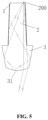
- FIG. 1 is a side view of an automotive lamp optical element of an embodiment of the present application
- FIG. 2 is a top view of an automotive lamp optical element of an embodiment of the present application
- FIG. 3 is a rear view of an automotive lamp optical element of an embodiment of the present application.
- FIG. 4 is a front view of an automotive lamp optical element of an embodiment of the present application.
- FIG. 5 is a top view of an automotive lamp module of an embodiment of the present application.
- 1 light-incident portion
- 11 light-incident structure
- 2 transmission portion
- 3 light-emitting portion
- 31 light-emitting convex surface
- 200 light source.
- This embodiment provides an automotive lamp optical element, which can be used in a matrix headlamp module.
- the matrix headlamp module is an automotive lamp module capable of dividing a high beam illumination area into multiple illumination areas, and can shield a target object in front of the vehicle by turning off the corresponding light source so as to avoid dazzling other road users and improve the driving safety performance.
- the automotive lamp optical element includes a light-incident portion 1 , a transmission portion 2 and a light-emitting portion 3 connected in sequence.
- the light-incident portion 1 is provided with at least one light-incident structure 11 configured to converge light.
- the area of a cross section of the transmission portion 2 gradually increases in a light transmission direction.
- a light-emitting convex surface 31 is formed on one end of the light-emitting portion 3 facing away from the transmission portion 2 .
- An optical axis is an axis extending in a front-rear direction of the automotive lamp optical element and passing through a focal point of the light-emitting portion 3 , and the light transmission direction is defined as a direction along the optical axis from the light-incident portion 1 toward the light-emitting portion 3 .
- the cross section is defined as a plane perpendicular to the optical axis.
- a light-incident convex surface is formed on one end of the light-incident structure 11 facing away from the transmission portion 2 .
- the light-incident structure 11 may be another converging structure.
- the light-incident structure 11 is a converging cup.
- five light-incident structures 11 are provided and arranged in a row.
- multiple light-incident structures 11 are provided as needed, and the multiple light-incident structures 11 may be distributed in rows and columns.
- the area of the cross section of the transmission portion 2 gradually increases in a light transmission direction, that is, the area of the cross section of the transmission portion 2 gradually increases from one end of the transmission portion 2 adjacent to the light-incident portion 1 toward one end of the transmission portion 2 adjacent to the light-emitting portion 3 .
- Each of four side surfaces of the transmission portion 2 except two end surfaces is a flared trapezoid in the light transmission direction, and every two opposite side surfaces of the four side surfaces have a same shape.
- five light-incident structures 11 are provided and arranged in a row.
- two opposite side surfaces of the transmission portion 2 are a flared trapezoid in the light transmission direction.
- Such structure can collect the light well and can further make the size of the whole automotive lamp optical element as less as possible, avoiding unnecessary structures.
- the other two opposite side surfaces of the transmission portion 2 are a flared trapezoid in the light transmission direction so as to collect the light.
- FIG. 1 two opposite side surfaces of the transmission portion 2 are a flared trapezoid in the light transmission direction.
- the width of the transmission portion 2 is less than the width of the light-emitting portion 3
- the height H 1 of the transmission portion 2 is less than the height H 2 of the light-emitting portion 3
- the width of the transmission portion 2 in a left-right direction is less than the width of the light-emitting portion 3 in the left-right direction so as to prevent part of the light emitted by a light source 200 from being emitted out of a side surface of the light-emitting portion 3 .
- the height of the transmission portion 2 in an up-down direction is less than the height of the light-emitting portion 3 in the up-down direction so that the light emitted by the light source 200 can be refracted out of only the light-emitting convex surface 31 of the light-emitting portion 3 .
- Incident light emitted by the light source 200 is converged by the light-incident portion 1 , transmitted to the light-emitting portion 3 through the transmission portion 2 , and refracted out of the light-emitting portion 3 .
- part of the light is emitted directly out of the side surface of the transmission portion 2 or reflected by the side surface of the transmission portion 2 and then refracted out of the light-emitting portion 3 , and thus a large amount of stray light is generated, which will affect the optical performance of the automotive lamp light shape.
- light is prevented from being emitted out of the side surfaces of the whole optical element by painting the side surfaces of the whole optical element black.
- the side surfaces of the entire optical element all are painted black, since the light-emitting portion 3 is exposed outside the lamp body, the black paint on the side surfaces of the optical element may affect the permeability and aesthetics of the optical element.
- a skin pattern may be also arranged on the side surfaces of the optical element to eliminate the stray light, but this method cannot completely avoid the stray light.
- the side surfaces of the transmission portion 2 are coated with a light absorbing layer, and the light absorbing layer is, for example, a light absorbing black paint, so as to prevent the light from being emitted out of the side surfaces of the transmission portion 2 .
- the side surfaces of the light-emitting portion 3 are not coated with the black paint, permeability and aesthetics of the part of the automotive lamp optical element exposed outside are ensured.
- the light-emitting convex surface 31 of the light-emitting portion 3 protrudes forward, and forms a double convex lens with the light-incident structure 11 for collecting, aligning and then projecting the incident light forward to form a corresponding automotive lamp light shape.
- the shape of the cross section of the light-emitting portion 3 perpendicular to the optical axis is a parallelogram when viewed directly in front of the automotive lamp optical element.
- This shape is only exemplary, and the shape of a lens having the light-emitting convex surface 31 may be configured as a desired shape as required in a case where there is a relatively small influence on the light-emitting convex surface 31 .
- the area of the cross section of the light-emitting portion 3 may gradually decrease in the light transmission direction from one end of the light-emitting portion 3 adjacent to the transmission portion 2 toward one end of the light-emitting portion 3 facing away from the transmission portion 2 .
- the left side in FIG. 2 is defined as the left side surface of the light-emitting portion 3 .
- the right side in FIG. 2 is defined as the right side surface of the light-emitting portion 3 .
- the left and right side surfaces of the light-emitting portion 3 are gradually converged toward the optical axis direction along the light transmission direction, so that light emitted from the light source 200 and emitted to the left and right side surfaces of the light-emitting portion 3 can be totally reflected.
- the totally reflected light is transmitted to the light-emitting convex surface 31 of the light-emitting portion 3 and then totally reflected, thereby preventing the light emitted from the light source 200 from being refracted by the light-emitting convex surface 31 and then reflected by the light-emitting portion 3 . Since in such design, an incident angle of most of the light emitted from the light source to the side surfaces of the light-emitting portion is greater than a total reflection critical angle of the light-emitting portion 3 , there is no refraction. For example, an optical path of the light incident on the light-emitting portion 3 is as follows.
- the light incident on the right side surface of the light-emitting portion 3 can be firstly totally reflected to the light-emitting convex surface 31 of the light-emitting portion 3 , secondly totally reflected on the light-emitting convex surface 31 of the light-emitting portion 3 and reflected to the left side surface of the light-emitting portion 3 , and thirdly totally reflected again to the right side surface of the transmission portion 2 on the left side surface of the light-emitting portion 3 .
- the light incident on the left side surface of the light-emitting portion 3 can be firstly totally reflected to the light-emitting convex surface 31 of the light-emitting portion 3 , secondly totally reflected to the right side surface of the light-emitting portion 3 on the light-emitting convex surface 31 of the light-emitting portion 3 , and thirdly totally reflected again to the left side surface of the transmission portion 2 on the right side surface of the light-emitting portion 3 .
- all side surfaces of the transmission portion 2 are coated with the light absorbing black paint, the light totally reflected to the left and right side surfaces of the transmission portion 2 is stopped from being reflected.
- FIG. 4 is a front view of an automotive lamp optical element.
- the light-incident portion 1 , the transmission portion 2 and the light-emitting portion 3 are integrally formed.
- the light-incident portion 1 , the transmission portion 2 and the light-emitting portion 3 are all made of transparent plastics, silica gel, or glass. These materials are transparent and have a good light propagation property.
- the commonly used plastics are polymethyl methacrylate (PMMA) or polycarbonate (PC).
- the automotive lamp optical element provided by this embodiment is provided with the incident portion 1 , the transmission portion 2 and the light-emitting portion 3 connected in sequence.
- the incident portion 1 is provided with at least one light-incident structure 11 configured to converge light.
- the area of the cross section of the transmission portion 2 gradually increases in the light transmission direction from one end of the transmission portion 2 adjacent to the light-incident portion 1 toward one end of the transmission portion 2 adjacent to the light-emitting portion 3 , so that the light can be better transmitted and the whole automotive lamp optical element is small in size, thereby avoiding unnecessary structures.
- the light-emitting convex surface 31 is formed on one end of the light-emitting portion 3 facing away from the transmission portion 2 , the light is converged by the light-incident structure 11 , transmitted to the light-emitting portion 3 via the transmission portion 2 , and finally reflected out of the light-emitting convex surface 31 and projected to form an automotive lamp light shape.
- the automotive lamp optical element provided by this embodiment is simple in structure, small in size, easy to install, and has high optical system accuracy, low dimming difficulty, low cost, and no stray light.
- the automotive lamp module includes the above automotive lamp optical element, and further includes at least one light source 200 .
- the at least one light source 200 is disposed opposite to and in one-to-one correspondence with the at least one light-incident structure 11 .
- a leftmost light source 200 as an example, a first part of the light emitted by the leftmost light source 200 is directly emitted to the light-emitting convex surface 31 of the light-emitting portion 3 , and is projected by the light-emitting convex surface 31 of the light-emitting portion 3 to form an automotive lamp light shape.
- a second part of the light emitted by the leftmost light source 200 is emitted to the side surfaces of the transmission portion 2 and is cut off by the side surfaces of the transmission portion 2 coated with the light absorbing black paint, and cannot be emitted out of or reflected by the side surfaces of the transmission portion 2 .
- a third part of the light emitted by the leftmost light source 200 is emitted to the right side surface of the light-emitting portion 3 , totally reflected to the light-emitting convex surface 31 of the light-emitting portion 3 , totally reflected from the light-emitting convex surface 31 of the light-emitting portion 3 to the left side surface of the light-emitting portion 3 , and then totally reflected from the left side surface of the light-emitting portion 3 to the right side surface of the transmission portion 2 and cut off.
- a single automotive lamp module is provided with five light sources 200
- the automotive lamp provided with three of the above automotive lamp modules can form 15 illumination areas, that is, a matrix headlamp of the automotive has 15 pixels, which can realize the subdivision illumination of 15 areas.
- the light source 200 corresponding to the area is turned off, so that this area darkens, preventing other road users from dazzling.
- the size of the above automotive lamp optical element is related to the number of light sources 200 of a single automotive lamp module. The less the number of light sources 200 is, the smaller the size of the automotive lamp optical element is.
- an opening size of the light-emitting convex surface 31 of the light-emitting portion 3 is about 20 mm high and about 10 mm wide, which is much less than an opening size of a lens of the existing matrix headlamp module, so that the automotive lamp optical element can adapt to much richer and more diverse automotive lamp shapes.
- the light-incident structures 11 may also be arranged in multiple rows, and a single automotive lamp module can realize a matrix light shape with multiple rows. In this embodiment, only five light-incident structures 11 in a single row are schematically illustrated.
- This embodiment also provides a vehicle.
- the vehicle includes the above automotive lamp module, which is easy to install and has high optical system accuracy, low dimming difficulty, low cost and no stray light.
- the automotive lamp optical element, the automotive lamp module and the vehicle provided by this embodiment have advantages as follows.
- the size is small.
- the whole automotive lamp module only needs the light source 200 and one automotive lamp optical element.
- the automotive lamp optical element is highly compact and integrated and has a very small three-dimensional volume, and even equipped with corresponding accessories such as a radiator, a mounting bracket and the like, the whole automotive lamp module still has a very small size.
- the structure is simple. For the component configuration, there is no need to set various complicated corresponding optical system accessories such as the mounting bracket for positioning and mounting the primary optical element and the secondary optical element, so that the structure of the automotive lamp module is simple.
- the optical system accuracy is high. Only one automotive lamp optical element needs to be provided, the structure of this automotive lamp optical element is also not complicated, and the manufacturing accuracy of this automotive lamp optical element is relatively easy to be ensured. Therefore, in a case where the manufacturing accuracy of this automotive lamp optical element meets the requirement, only the accuracy of the relative position between one automotive lamp optical element and the light source 200 needs to be ensured when the automotive lamp optical element is assembled, and the accuracy of the relative positions between multiple automotive lamp optical elements and the light source 200 does not need to be satisfied, so that the optical system accuracy is high.
- the dimming difficulty is low. It is only necessary to ensure the accuracy of the relative position between one automotive lamp optical element and the light source 200 . Compared with the optical system requiring more dimming designs in the existing art, the automotive lamp optical element provided by this embodiment reduces the dimming difficulty.
- This automotive lamp module has a simple structure and a small number, so that both manufacturing and processing costs are low.
- the transmission portion 2 is coated with non-glare black paint, such as matte black paint, and the left and right side surfaces of the light-emitting portion 3 and the light-emitting convex surface 31 are configured as total reflection surfaces so that the light cannot be emitted out of the side surfaces of this optical element or emitted after being reflected by the side surfaces, so that substantially no stray light is generated, thereby ensuring the quality of the automotive lamp light shape.
- non-glare black paint such as matte black paint
- such arrangement reduces the size of the transmission portion 2 , so that the size of the automotive lam optical element is further reduced; and on the other hand, since the side surfaces of the light-emitting portion 3 are not coated with the black paint, permeability and aesthetics of the part of the automotive lamp optical element exposed outside are ensured.
Landscapes
- Engineering & Computer Science (AREA)
- General Engineering & Computer Science (AREA)
- Physics & Mathematics (AREA)
- Microelectronics & Electronic Packaging (AREA)
- Optics & Photonics (AREA)
- Mechanical Engineering (AREA)
- Mathematical Physics (AREA)
- Non-Portable Lighting Devices Or Systems Thereof (AREA)
- Lighting Device Outwards From Vehicle And Optical Signal (AREA)
- Planar Illumination Modules (AREA)
Abstract
Description
Claims (15)
Applications Claiming Priority (7)
| Application Number | Priority Date | Filing Date | Title |
|---|---|---|---|
| CN201920859938.7 | 2019-06-05 | ||
| CN201920859938 | 2019-06-05 | ||
| CN201910488336 | 2019-06-05 | ||
| CN201910488336.X | 2019-06-05 | ||
| CN201910730411.9 | 2019-08-08 | ||
| CN201910730411 | 2019-08-08 | ||
| PCT/CN2020/070867 WO2020244228A1 (en) | 2019-06-05 | 2020-01-08 | Automotive lamp optical element, automotive lamp module, and vehicle |
Publications (2)
| Publication Number | Publication Date |
|---|---|
| US20220316677A1 US20220316677A1 (en) | 2022-10-06 |
| US11879608B2 true US11879608B2 (en) | 2024-01-23 |
Family
ID=69919893
Family Applications (6)
| Application Number | Title | Priority Date | Filing Date |
|---|---|---|---|
| US17/616,678 Active 2040-07-17 US12085246B2 (en) | 2019-06-05 | 2019-09-05 | Vehicle headlamp and vehicle |
| US16/965,178 Active 2041-04-05 US11708953B2 (en) | 2019-06-05 | 2019-09-16 | Headlight optical element, headlight module, vehicle headlight and vehicle |
| US17/046,582 Active 2040-12-31 US11674653B2 (en) | 2019-06-05 | 2019-09-27 | Headlight optical element, headlight module, vehicle headlight and vehicle |
| US17/596,007 Active 2040-03-24 US12013092B2 (en) | 2019-06-05 | 2020-01-08 | Automotive lamp optical element and automotive headlamp |
| US17/596,008 Active 2040-03-03 US11879608B2 (en) | 2019-06-05 | 2020-01-08 | Automotive lamp optical element, automotive lamp module, and vehicle |
| US17/419,595 Active 2040-07-25 US11674654B2 (en) | 2019-06-05 | 2020-04-17 | Vehicle light optical element, vehicle light module, vehicle headlight, and vehicle |
Family Applications Before (4)
| Application Number | Title | Priority Date | Filing Date |
|---|---|---|---|
| US17/616,678 Active 2040-07-17 US12085246B2 (en) | 2019-06-05 | 2019-09-05 | Vehicle headlamp and vehicle |
| US16/965,178 Active 2041-04-05 US11708953B2 (en) | 2019-06-05 | 2019-09-16 | Headlight optical element, headlight module, vehicle headlight and vehicle |
| US17/046,582 Active 2040-12-31 US11674653B2 (en) | 2019-06-05 | 2019-09-27 | Headlight optical element, headlight module, vehicle headlight and vehicle |
| US17/596,007 Active 2040-03-24 US12013092B2 (en) | 2019-06-05 | 2020-01-08 | Automotive lamp optical element and automotive headlamp |
Family Applications After (1)
| Application Number | Title | Priority Date | Filing Date |
|---|---|---|---|
| US17/419,595 Active 2040-07-25 US11674654B2 (en) | 2019-06-05 | 2020-04-17 | Vehicle light optical element, vehicle light module, vehicle headlight, and vehicle |
Country Status (6)
| Country | Link |
|---|---|
| US (6) | US12085246B2 (en) |
| EP (2) | EP3982033B1 (en) |
| JP (4) | JP7330272B2 (en) |
| CN (9) | CN112050162A (en) |
| DE (2) | DE112019005799B4 (en) |
| WO (6) | WO2020244079A1 (en) |
Families Citing this family (17)
| Publication number | Priority date | Publication date | Assignee | Title |
|---|---|---|---|---|
| CN210740255U (en) * | 2019-06-05 | 2020-06-12 | 华域视觉科技(上海)有限公司 | Car light optical element, car light module, vehicle headlamp and vehicle |
| CN112050162A (en) * | 2019-06-05 | 2020-12-08 | 华域视觉科技(上海)有限公司 | Car light optical element, car light module and vehicle |
| CN211822197U (en) * | 2020-01-21 | 2020-10-30 | 华域视觉科技(上海)有限公司 | Headlamp module, headlamp and vehicle |
| CN113958921A (en) * | 2020-12-29 | 2022-01-21 | 华域视觉科技(上海)有限公司 | Lighting module, lighting device and vehicle |
| DE112021003257T5 (en) * | 2020-06-16 | 2023-05-04 | Idemitsu Kosan Co., Ltd. | Interior component for vehicle lamp |
| CN112781002B (en) * | 2020-07-17 | 2025-07-25 | 华域视觉科技(上海)有限公司 | Vehicle high beam module, vehicle head lamp and vehicle |
| CN112797368A (en) * | 2020-09-08 | 2021-05-14 | 华域视觉科技(上海)有限公司 | A vehicle headlamp optical system, vehicle headlamp and vehicle |
| CN113266797A (en) * | 2020-11-16 | 2021-08-17 | 华域视觉科技(上海)有限公司 | High-beam and low-beam integrated car lamp optical element, car lamp module, car lamp and car |
| CN214038234U (en) * | 2020-11-27 | 2021-08-24 | 华域视觉科技(上海)有限公司 | High beam optical assembly, high beam lighting unit, car lamp and vehicle |
| CN214038235U (en) | 2020-11-27 | 2021-08-24 | 华域视觉科技(上海)有限公司 | High beam optical element, high beam illumination unit, and vehicle |
| CN113418172B (en) * | 2020-12-09 | 2025-06-13 | 华域视觉科技(上海)有限公司 | A low beam optical element, a vehicle light module, a vehicle lighting device and a vehicle |
| CZ202272A3 (en) * | 2022-02-15 | 2023-08-23 | Hella Autotechnik Nova, S.R.O. | Headlight for a car |
| TWI826309B (en) * | 2023-04-21 | 2023-12-11 | 矜輝實業有限公司 | Structure of car lamp |
| TWI826310B (en) * | 2023-04-21 | 2023-12-11 | 矜輝實業有限公司 | Composite surface light-guiding car lamp lens |
| CN116518325B (en) * | 2023-04-25 | 2025-11-28 | 马瑞利汽车零部件(芜湖)有限公司 | Optical system for car lamp and car |
| CN116624801A (en) * | 2023-04-25 | 2023-08-22 | 马瑞利汽车零部件(芜湖)有限公司 | Auto lamp thick-walled outer lens, processing method and system |
| TWI870272B (en) * | 2024-03-27 | 2025-01-11 | 福安工業股份有限公司 | Vehicle optical lens |
Citations (30)
| Publication number | Priority date | Publication date | Assignee | Title |
|---|---|---|---|---|
| US20040156209A1 (en) | 2003-02-10 | 2004-08-12 | Hiroyuki Ishida | Vehicular headlamp and optical unit |
| CN101311769A (en) | 2007-05-24 | 2008-11-26 | 创盟科技股份有限公司 | Reflective imaging system |
| EP2306075A2 (en) | 2009-10-05 | 2011-04-06 | Automotive Lighting Reutlingen GmbH | Motor vehicle headlamp with semiconductor sources for generating different light distributions |
| CN102032519A (en) | 2009-10-05 | 2011-04-27 | 汽车照明罗伊特林根有限公司 | Light module for a lighting device of a motor vehicle |
| EP2340984A1 (en) | 2009-12-30 | 2011-07-06 | Genius Electronic Optical Co. Ltd. | Light guide lens and bicycle headlight including the same |
| JP2013037963A (en) | 2011-08-10 | 2013-02-21 | Koito Mfg Co Ltd | Vehicular lamp |
| CN103090286A (en) | 2011-10-27 | 2013-05-08 | 汽车照明罗伊特林根有限公司 | Headlight projection module for a motor vehicle |
| WO2014019912A1 (en) | 2012-08-03 | 2014-02-06 | Automotive Lighting Reutlingen Gmbh | Light guiding element and light module |
| US20140133168A1 (en) * | 2012-11-09 | 2014-05-15 | Osram Gmbh | Lighting device |
| US20140204602A1 (en) * | 2011-08-08 | 2014-07-24 | Zizala Lichtsysteme Gmbh | Led light-source module for an led motor vehicle headlight |
| DE102013013995A1 (en) | 2013-01-23 | 2014-07-24 | Docter Optics Se | Headlight lens for a vehicle headlight |
| CN104704288A (en) | 2012-11-08 | 2015-06-10 | 博士光学欧洲股份公司 | Headlight lenses for vehicle headlights |
| JP2015176745A (en) | 2014-03-14 | 2015-10-05 | スタンレー電気株式会社 | Lens body and vehicle lighting appliance |
| CN105358900A (en) | 2013-04-26 | 2016-02-24 | 三菱电机株式会社 | Headlight module for vehicle, headlight unit for vehicle, and headlight device for vehicle |
| JP2016029621A (en) | 2014-07-25 | 2016-03-03 | スタンレー電気株式会社 | Lens body and vehicle lighting fixture |
| JP2016096143A (en) | 2014-11-12 | 2016-05-26 | ドクター エンジニール ハー ツェー エフ ポルシェ アクチエンゲゼルシャフトDr. Ing. h.c. F. Porsche Aktiengesellschaft | Lighting device |
| US20160368414A1 (en) * | 2014-12-19 | 2016-12-22 | Sl Corporation | Adaptive driving beam headlamp for vehicle |
| EP3150905A1 (en) | 2014-05-23 | 2017-04-05 | Stanley Electric Co., Ltd. | Lens body, combined lens body, and vehicular lamp fitting |
| DE102016006605A1 (en) | 2015-10-07 | 2017-04-13 | Docter Optics Se | Headlight lens for a vehicle headlight |
| FR3050010A1 (en) | 2016-04-11 | 2017-10-13 | Valeo Vision | COMPACT LIGHT EMITTING MODULE, DEVICE AND PROJECTOR THEREOF FOR MOTOR VEHICLE |
| WO2017185118A1 (en) | 2016-04-29 | 2017-11-02 | Zkw Group Gmbh | Lighting unit for a motor vehicle headlight for generating a light bundle having a light-dark boundary |
| CN107489955A (en) | 2016-06-10 | 2017-12-19 | 欧司朗股份有限公司 | Lighting device, corresponding lamp and method |
| JP2018055907A (en) | 2016-09-28 | 2018-04-05 | 株式会社日立情映テック | Vehicle headlamp device |
| CN207527498U (en) | 2017-09-14 | 2018-06-22 | 上海小糸车灯有限公司 | A kind of collimation lens and its automobile-used optics module |
| CN208107967U (en) | 2018-04-13 | 2018-11-16 | 华域视觉科技(上海)有限公司 | Far and near photosystem and car light based on light guide |
| US10139646B2 (en) * | 2015-08-06 | 2018-11-27 | Valeo Vision | Transparent material light-emitting module with two reflection faces |
| US10139068B2 (en) * | 2015-09-17 | 2018-11-27 | Zkw Group Gmbh | Light source arrangement in a pixel-light light module |
| US10203081B2 (en) * | 2017-06-05 | 2019-02-12 | Panasonic Intellectual Property Management Co., Ltd. | Lighting device and headlight for vehicle |
| CN208871529U (en) | 2018-08-03 | 2019-05-17 | 常熟理工学院 | A kind of car headlamp unit |
| US10563832B2 (en) * | 2016-09-30 | 2020-02-18 | H.A. Automotive Systems, Inc. | Condenser for low-beam vehicle light module |
Family Cites Families (73)
| Publication number | Priority date | Publication date | Assignee | Title |
|---|---|---|---|---|
| JPH03133004A (en) * | 1989-10-18 | 1991-06-06 | Mitsubishi Motors Corp | Inner lens and its manufacture |
| US5614788A (en) * | 1995-01-31 | 1997-03-25 | Autosmart Light Switches, Inc. | Automated ambient condition responsive daytime running light system |
| JPH0917210A (en) * | 1995-06-28 | 1997-01-17 | Koito Mfg Co Ltd | Optical axis adjusting structure for vehicle lamp and assembly method thereof |
| FR2792710B1 (en) | 1999-04-23 | 2001-08-03 | Valeo Vision | PROJECTOR ASSEMBLY FOR A MOTOR VEHICLE CAPABLE OF TRANSMITTING A SELECTIVELY ENRICHED CUTTING BEAM |
| DE19946297A1 (en) | 1999-09-28 | 2001-04-12 | Philips Corp Intellectual Pty | Light bulb |
| US6527411B1 (en) | 2000-08-01 | 2003-03-04 | Visteon Corporation | Collimating lamp |
| JP4339143B2 (en) | 2004-02-10 | 2009-10-07 | 株式会社小糸製作所 | Vehicle lamp unit |
| DE102004056252A1 (en) | 2004-10-29 | 2006-05-04 | Osram Opto Semiconductors Gmbh | Lighting device, vehicle headlight and method for producing a lighting device |
| JP4211736B2 (en) * | 2004-11-10 | 2009-01-21 | 市光工業株式会社 | Vehicle lighting |
| JP4413839B2 (en) | 2005-09-13 | 2010-02-10 | 株式会社小糸製作所 | Vehicle headlamp lamp unit |
| DE102006039705A1 (en) * | 2006-08-18 | 2008-02-28 | Schott Ag | Lens attachment for a headlight |
| DE102006053020A1 (en) | 2006-11-10 | 2008-05-15 | Hella Kgaa Hueck & Co. | Lens for vehicle headlight, has lens body with light input face for feeding light emitted by light source, where arc-shaped light output face is provided for decoupling of light |
| CN201050708Y (en) * | 2007-04-30 | 2008-04-23 | 秦硕 | Tape form light source production device |
| CN101109495A (en) * | 2007-09-03 | 2008-01-23 | 力帆实业(集团)有限公司 | Optical axis adjustable headlights for automobiles |
| JP5168551B2 (en) * | 2008-03-26 | 2013-03-21 | スタンレー電気株式会社 | Projection lens for lamp, optical unit for vehicle, and lamp for vehicle |
| CN201561363U (en) | 2009-10-26 | 2010-08-25 | 上海小糸车灯有限公司 | Assembly structure of LED illumination vehicle lamp high-low lamp switching device |
| JP4991001B2 (en) * | 2009-12-28 | 2012-08-01 | シャープ株式会社 | Lighting device |
| AT512590B1 (en) * | 2012-03-12 | 2013-11-15 | Zizala Lichtsysteme Gmbh | Light guide element for a laser vehicle headlight and vehicle headlights |
| DE102013006707B4 (en) * | 2012-05-26 | 2025-11-27 | Docter Optics Se | Headlight lens for a vehicle headlight |
| US9217552B2 (en) | 2012-07-27 | 2015-12-22 | Sharp Kabushiki Kaisha | Illumination device |
| JP6164518B2 (en) * | 2013-03-18 | 2017-07-19 | スタンレー電気株式会社 | Vehicle headlamp |
| JP5847105B2 (en) | 2013-03-22 | 2016-01-20 | 株式会社小糸製作所 | Vehicle lighting |
| CN203464209U (en) | 2013-04-26 | 2014-03-05 | 周路珍 | LED head lamp employing air-flow heat-dissipating device for dissipation heat |
| FR3012867A1 (en) * | 2013-11-07 | 2015-05-08 | Valeo Vision | PRIMARY OPTICAL ELEMENT, LIGHT MODULE AND PROJECTOR FOR MOTOR VEHICLE |
| JP6214446B2 (en) | 2014-03-26 | 2017-10-18 | 三菱電機株式会社 | Automotive headlamp |
| JP2016006729A (en) * | 2014-06-20 | 2016-01-14 | スタンレー電気株式会社 | Vehicular lighting |
| JP6083011B2 (en) | 2014-06-27 | 2017-02-22 | パナソニックIpマネジメント株式会社 | Lighting device |
| CN204005632U (en) | 2014-07-01 | 2014-12-10 | 上海汽车集团股份有限公司 | A kind of automobile-used dipped headlights |
| WO2016013340A1 (en) | 2014-07-25 | 2016-01-28 | スタンレー電気株式会社 | Lighting fixture for vehicle |
| FR3028004B1 (en) | 2014-10-30 | 2019-08-02 | Aml Systems | SEMI-ELLIPTICAL PROJECTOR COMPRISING A RADIATOR |
| CN204387890U (en) | 2014-11-28 | 2015-06-10 | 广州市雷腾照明科技有限公司 | A kind of headlamp |
| FR3039630A1 (en) * | 2015-07-28 | 2017-02-03 | Valeo Vision | LIGHTING SYSTEM FOR MOTOR VEHICLE PROJECTOR |
| FR3041738B1 (en) * | 2015-09-28 | 2020-01-17 | Valeo Vision | PRIMARY OPTICAL ELEMENT FOR LIGHT MODULE OF MOTOR VEHICLE |
| CN105444085B (en) | 2015-12-14 | 2018-05-04 | 成都恒坤光电科技有限公司 | A kind of light collection device and headlamp with shade |
| FR3048060B1 (en) | 2016-02-22 | 2019-04-05 | Valeo Vision | LIGHT BEAM PROJECTION DEVICE WITH LIGHT SOURCE SUBMATHES, LIGHTING MODULE AND PROJECTOR PROVIDED WITH SUCH A DEVICE |
| CN205640631U (en) | 2016-04-26 | 2016-10-12 | 曹红曲 | Car passing lamp lighting components and car passing lamp |
| JP6761668B2 (en) * | 2016-05-17 | 2020-09-30 | 株式会社小糸製作所 | Vehicle lighting |
| JP6767716B2 (en) | 2016-05-26 | 2020-10-14 | パナソニックIpマネジメント株式会社 | Vehicle headlights and vehicles using them |
| TWI616685B (en) * | 2016-05-31 | 2018-03-01 | 隆達電子股份有限公司 | Lighting system |
| DE102016006604A1 (en) * | 2016-06-02 | 2017-12-07 | Docter Optics Se | Headlight lens for a vehicle headlight |
| JP6671012B2 (en) * | 2016-07-15 | 2020-03-25 | パナソニックIpマネジメント株式会社 | Vehicle headlights |
| CN206001356U (en) | 2016-07-29 | 2017-03-08 | 浙江金驹汽车零部件有限公司 | A kind of LED illumination module of distance-light unification |
| CN205991413U (en) * | 2016-08-04 | 2017-03-01 | 上海小糸车灯有限公司 | A kind of dipped beam car light module |
| FR3056688B1 (en) * | 2016-09-26 | 2018-11-02 | Valeo Vision | BI-FUNCTION LIGHTING MODULE IN TRANSPARENT MATERIAL |
| FR3056694B1 (en) * | 2016-09-29 | 2020-06-19 | Valeo Vision | LIGHTING DEVICE FOR A MOTOR VEHICLE COMPRISING A LIGHT GUIDE |
| JP6840993B2 (en) * | 2016-10-25 | 2021-03-10 | 市光工業株式会社 | Vehicle lighting |
| CN206419848U (en) * | 2016-12-23 | 2017-08-18 | 市光法雷奥(佛山)汽车照明系统有限公司 | Light-emitting device and illuminating module for motor vehicles |
| JP6818542B2 (en) * | 2016-12-26 | 2021-01-20 | スタンレー電気株式会社 | Lens holding structure and vehicle lighting equipment |
| DE112017006796B4 (en) | 2017-01-12 | 2022-05-19 | Hasco Vision Technology Co., Ltd. | TRANSPARENT PHOTOCONDUCTOR WITH LIGHT SHIELDING FUNCTION AND APPLICATION THEREOF |
| JP6840606B2 (en) * | 2017-04-14 | 2021-03-10 | スタンレー電気株式会社 | Lens body and vehicle lighting equipment |
| KR101907372B1 (en) * | 2017-04-26 | 2018-10-12 | 현대모비스 주식회사 | Head lamp apparatus |
| DE102017208241A1 (en) * | 2017-05-16 | 2018-11-22 | Osram Gmbh | LIGHT GUIDE FOR PRODUCING A PRESENT LIGHT IMAGE OF A PIXEL OF A MATRIX LIGHT |
| CN208041995U (en) * | 2017-06-28 | 2018-11-02 | 上海小糸车灯有限公司 | A kind of dipped beam car light module |
| US10408408B2 (en) | 2017-08-24 | 2019-09-10 | Ford Global Technologies, Llc | Automotive headlamp with S-polarizer filter to reduce glare |
| CN107740995A (en) * | 2017-10-25 | 2018-02-27 | 上海小糸车灯有限公司 | A kind of LED total reflection lens, LED light conductors and automobile lamp |
| CN107893963B (en) * | 2017-11-15 | 2024-05-03 | 华域视觉科技(上海)有限公司 | Light optical system for vehicle |
| CN207661691U (en) * | 2017-12-11 | 2018-07-27 | 堤维西交通工业股份有限公司 | headlights |
| CN207975591U (en) * | 2018-03-08 | 2018-10-16 | 北京车和家信息技术有限公司 | Light-strip, car light and vehicle for car light |
| CN108518645A (en) | 2018-05-14 | 2018-09-11 | 铠龙东方汽车有限公司 | A kind of front fog lamp of automobile reducing veiling glare |
| JP6590996B1 (en) | 2018-06-01 | 2019-10-16 | 株式会社小糸製作所 | Vehicle lighting |
| FR3081969B1 (en) * | 2018-06-01 | 2021-12-31 | Valeo Vision | LIGHT MODULE FOR A MOTOR VEHICLE, AND LIGHTING AND/OR SIGNALING DEVICE PROVIDED WITH SUCH A MODULE |
| CN208846328U (en) | 2018-07-24 | 2019-05-10 | 常州九鼎车业股份有限公司 | Headlight for vehicles assembly |
| FR3084755B1 (en) * | 2018-08-02 | 2020-12-18 | Valeo Vision | OPTICAL PART INCLUDING A BLOCK WITH A BENDING DIOPTER FOR TWO BEAMS |
| CN109357235A (en) | 2018-09-25 | 2019-02-19 | 河海大学常州校区 | A matrix car lamp system based on flip-chip LED white light chip |
| CN109611780A (en) * | 2019-01-29 | 2019-04-12 | 华域视觉科技(上海)有限公司 | Motor vehicle high beam lighting module and lamp |
| CN109268774A (en) | 2018-10-25 | 2019-01-25 | 华域视觉科技(上海)有限公司 | A kind of double matrix form illumination module and its auxiliary lighting method |
| CN208804624U (en) | 2018-11-15 | 2019-04-30 | 浙江嘀视科技有限公司 | A kind of double optical lens and car light |
| CN109539168A (en) | 2019-01-11 | 2019-03-29 | 华域视觉科技(上海)有限公司 | Distance light brightness reinforcing device, LED module unit, car light, automobile |
| CN109654448B (en) | 2019-02-28 | 2021-11-23 | 华域视觉科技(上海)有限公司 | Car lamp reflecting surface and machining method thereof, car lamp reflecting mirror, car lamp module and car |
| JP6919860B2 (en) | 2019-03-19 | 2021-08-18 | 丸茂電機株式会社 | Lamps for wall irradiation and lighting equipment using them |
| CN210373264U (en) * | 2019-05-22 | 2020-04-21 | 华域视觉科技(上海)有限公司 | Car light optical element, car light illumination module, car light and vehicle |
| CN112050162A (en) * | 2019-06-05 | 2020-12-08 | 华域视觉科技(上海)有限公司 | Car light optical element, car light module and vehicle |
| US11781733B2 (en) * | 2019-06-05 | 2023-10-10 | Hasco Vision Technology Co., Ltd. | Vehicle lamp optical element, vehicle lamp module, vehicle headlamp and vehicle |
-
2019
- 2019-08-22 CN CN201910780623.8A patent/CN112050162A/en active Pending
- 2019-08-22 CN CN201921372161.8U patent/CN210219607U/en active Active
- 2019-08-22 CN CN201921377564.1U patent/CN210891432U/en active Active
- 2019-08-22 CN CN201910780200.6A patent/CN111396824B/en active Active
- 2019-08-22 CN CN201910780214.8A patent/CN111503590B/en active Active
- 2019-08-22 CN CN201921371967.5U patent/CN210462847U/en active Active
- 2019-08-22 CN CN201921377675.2U patent/CN210740254U/en not_active Withdrawn - After Issue
- 2019-08-22 CN CN201921373179.XU patent/CN210219602U/en active Active
- 2019-09-05 WO PCT/CN2019/104580 patent/WO2020244079A1/en not_active Ceased
- 2019-09-05 US US17/616,678 patent/US12085246B2/en active Active
- 2019-09-16 JP JP2021525808A patent/JP7330272B2/en active Active
- 2019-09-16 WO PCT/CN2019/105936 patent/WO2020244087A1/en not_active Ceased
- 2019-09-16 US US16/965,178 patent/US11708953B2/en active Active
- 2019-09-16 DE DE112019005799.5T patent/DE112019005799B4/en active Active
- 2019-09-27 US US17/046,582 patent/US11674653B2/en active Active
- 2019-09-27 WO PCT/CN2019/108398 patent/WO2020244103A1/en not_active Ceased
- 2019-09-27 JP JP2020556812A patent/JP7082682B2/en active Active
- 2019-09-27 DE DE112019001743.8T patent/DE112019001743B4/en active Active
-
2020
- 2020-01-08 JP JP2021571902A patent/JP7340041B2/en active Active
- 2020-01-08 JP JP2021571600A patent/JP7326488B2/en active Active
- 2020-01-08 EP EP20817827.7A patent/EP3982033B1/en active Active
- 2020-01-08 US US17/596,007 patent/US12013092B2/en active Active
- 2020-01-08 EP EP20819385.4A patent/EP3982035B1/en active Active
- 2020-01-08 WO PCT/CN2020/070935 patent/WO2020244229A1/en not_active Ceased
- 2020-01-08 WO PCT/CN2020/070867 patent/WO2020244228A1/en not_active Ceased
- 2020-01-08 US US17/596,008 patent/US11879608B2/en active Active
- 2020-04-17 WO PCT/CN2020/085405 patent/WO2020244316A1/en not_active Ceased
- 2020-04-17 CN CN202090000359.8U patent/CN217540606U/en active Active
- 2020-04-17 US US17/419,595 patent/US11674654B2/en active Active
Patent Citations (32)
| Publication number | Priority date | Publication date | Assignee | Title |
|---|---|---|---|---|
| US20040156209A1 (en) | 2003-02-10 | 2004-08-12 | Hiroyuki Ishida | Vehicular headlamp and optical unit |
| CN101311769A (en) | 2007-05-24 | 2008-11-26 | 创盟科技股份有限公司 | Reflective imaging system |
| EP2306075A2 (en) | 2009-10-05 | 2011-04-06 | Automotive Lighting Reutlingen GmbH | Motor vehicle headlamp with semiconductor sources for generating different light distributions |
| CN102032519A (en) | 2009-10-05 | 2011-04-27 | 汽车照明罗伊特林根有限公司 | Light module for a lighting device of a motor vehicle |
| EP2340984A1 (en) | 2009-12-30 | 2011-07-06 | Genius Electronic Optical Co. Ltd. | Light guide lens and bicycle headlight including the same |
| US20140204602A1 (en) * | 2011-08-08 | 2014-07-24 | Zizala Lichtsysteme Gmbh | Led light-source module for an led motor vehicle headlight |
| JP2013037963A (en) | 2011-08-10 | 2013-02-21 | Koito Mfg Co Ltd | Vehicular lamp |
| CN103090286A (en) | 2011-10-27 | 2013-05-08 | 汽车照明罗伊特林根有限公司 | Headlight projection module for a motor vehicle |
| US20150167913A1 (en) * | 2012-08-03 | 2015-06-18 | Automotive Lighting Reutlingen Gmbh | Light guiding element and light module |
| JP2015524986A (en) | 2012-08-03 | 2015-08-27 | オートモーティブ ライティング ロイトリンゲン ゲーエムベーハー | Optical guide member and optical module |
| WO2014019912A1 (en) | 2012-08-03 | 2014-02-06 | Automotive Lighting Reutlingen Gmbh | Light guiding element and light module |
| CN104704288A (en) | 2012-11-08 | 2015-06-10 | 博士光学欧洲股份公司 | Headlight lenses for vehicle headlights |
| US20140133168A1 (en) * | 2012-11-09 | 2014-05-15 | Osram Gmbh | Lighting device |
| DE102013013995A1 (en) | 2013-01-23 | 2014-07-24 | Docter Optics Se | Headlight lens for a vehicle headlight |
| CN105358900A (en) | 2013-04-26 | 2016-02-24 | 三菱电机株式会社 | Headlight module for vehicle, headlight unit for vehicle, and headlight device for vehicle |
| JP2015176745A (en) | 2014-03-14 | 2015-10-05 | スタンレー電気株式会社 | Lens body and vehicle lighting appliance |
| EP3150905A1 (en) | 2014-05-23 | 2017-04-05 | Stanley Electric Co., Ltd. | Lens body, combined lens body, and vehicular lamp fitting |
| JP2016029621A (en) | 2014-07-25 | 2016-03-03 | スタンレー電気株式会社 | Lens body and vehicle lighting fixture |
| JP2016096143A (en) | 2014-11-12 | 2016-05-26 | ドクター エンジニール ハー ツェー エフ ポルシェ アクチエンゲゼルシャフトDr. Ing. h.c. F. Porsche Aktiengesellschaft | Lighting device |
| US20160368414A1 (en) * | 2014-12-19 | 2016-12-22 | Sl Corporation | Adaptive driving beam headlamp for vehicle |
| US10139646B2 (en) * | 2015-08-06 | 2018-11-27 | Valeo Vision | Transparent material light-emitting module with two reflection faces |
| US10139068B2 (en) * | 2015-09-17 | 2018-11-27 | Zkw Group Gmbh | Light source arrangement in a pixel-light light module |
| DE102016006605A1 (en) | 2015-10-07 | 2017-04-13 | Docter Optics Se | Headlight lens for a vehicle headlight |
| FR3050010A1 (en) | 2016-04-11 | 2017-10-13 | Valeo Vision | COMPACT LIGHT EMITTING MODULE, DEVICE AND PROJECTOR THEREOF FOR MOTOR VEHICLE |
| WO2017185118A1 (en) | 2016-04-29 | 2017-11-02 | Zkw Group Gmbh | Lighting unit for a motor vehicle headlight for generating a light bundle having a light-dark boundary |
| CN107489955A (en) | 2016-06-10 | 2017-12-19 | 欧司朗股份有限公司 | Lighting device, corresponding lamp and method |
| JP2018055907A (en) | 2016-09-28 | 2018-04-05 | 株式会社日立情映テック | Vehicle headlamp device |
| US10563832B2 (en) * | 2016-09-30 | 2020-02-18 | H.A. Automotive Systems, Inc. | Condenser for low-beam vehicle light module |
| US10203081B2 (en) * | 2017-06-05 | 2019-02-12 | Panasonic Intellectual Property Management Co., Ltd. | Lighting device and headlight for vehicle |
| CN207527498U (en) | 2017-09-14 | 2018-06-22 | 上海小糸车灯有限公司 | A kind of collimation lens and its automobile-used optics module |
| CN208107967U (en) | 2018-04-13 | 2018-11-16 | 华域视觉科技(上海)有限公司 | Far and near photosystem and car light based on light guide |
| CN208871529U (en) | 2018-08-03 | 2019-05-17 | 常熟理工学院 | A kind of car headlamp unit |
Non-Patent Citations (2)
| Title |
|---|
| International Search Report for counterpart Application No. PCT/CN2020/070867 dated Mar. 26, 2020. |
| International Search Report for counterpart Application No. PCT/CN2020/070935 dated Mar. 26, 2020. |
Also Published As
Similar Documents
| Publication | Publication Date | Title |
|---|---|---|
| US11879608B2 (en) | Automotive lamp optical element, automotive lamp module, and vehicle | |
| US10962191B1 (en) | Lamp for vehicle | |
| EP3982041B1 (en) | Vehicle lamp optical element, vehicle lamp module, vehicle headlamp and vehicle | |
| JP6516495B2 (en) | Vehicle lamp | |
| CN114688494B (en) | Vehicle lighting | |
| JP2022517606A (en) | Vehicle lamp lighting module, vehicle lamp and vehicle | |
| US7997778B2 (en) | Vehicle light | |
| EP3885644B1 (en) | Low-beam optical module, low-beam illumination module, vehicle lamp and vehicle | |
| US11306891B1 (en) | Vehicle light optical element, vehicle light module, vehicle headlight and vehicle | |
| US10823364B2 (en) | Vehicular lamp | |
| EP3835649A1 (en) | Adaptive headlight for vehicles | |
| KR101106250B1 (en) | Vehicle signal lamp with integrated shield | |
| CN210373267U (en) | Car light module, car light and vehicle | |
| CN210319819U (en) | Car light module, car light and vehicle | |
| CN213542362U (en) | Car light optical assembly, car light module and vehicle | |
| KR102697982B1 (en) | Lamp for vehicle | |
| CN109973926B (en) | Lighting device for a motor vehicle | |
| CN220540932U (en) | Lamp for vehicle | |
| CN221171900U (en) | Far-near light integrated car lamp optical element, car lamp module and vehicle | |
| KR102697990B1 (en) | Lamp for vehicle | |
| KR20230036354A (en) | Lamp module and lamp for vehicle having the same | |
| CN120557589A (en) | Slow running light, rearview mirror lighting device and automobile |
Legal Events
| Date | Code | Title | Description |
|---|---|---|---|
| FEPP | Fee payment procedure |
Free format text: ENTITY STATUS SET TO UNDISCOUNTED (ORIGINAL EVENT CODE: BIG.); ENTITY STATUS OF PATENT OWNER: LARGE ENTITY |
|
| AS | Assignment |
Owner name: HASCO VISION TECHNOLOGY CO., LTD, CHINA Free format text: ASSIGNMENT OF ASSIGNORS INTEREST;ASSIGNORS:ZHANG, DAPAN;QIU, ZHIPING;ZHU, HE;AND OTHERS;REEL/FRAME:058301/0405 Effective date: 20211121 |
|
| STPP | Information on status: patent application and granting procedure in general |
Free format text: DOCKETED NEW CASE - READY FOR EXAMINATION |
|
| STPP | Information on status: patent application and granting procedure in general |
Free format text: RESPONSE TO NON-FINAL OFFICE ACTION ENTERED AND FORWARDED TO EXAMINER |
|
| STPP | Information on status: patent application and granting procedure in general |
Free format text: FINAL REJECTION MAILED |
|
| STPP | Information on status: patent application and granting procedure in general |
Free format text: ADVISORY ACTION MAILED |
|
| STPP | Information on status: patent application and granting procedure in general |
Free format text: DOCKETED NEW CASE - READY FOR EXAMINATION |
|
| STPP | Information on status: patent application and granting procedure in general |
Free format text: NOTICE OF ALLOWANCE MAILED -- APPLICATION RECEIVED IN OFFICE OF PUBLICATIONS |
|
| STPP | Information on status: patent application and granting procedure in general |
Free format text: PUBLICATIONS -- ISSUE FEE PAYMENT VERIFIED |
|
| STCF | Information on status: patent grant |
Free format text: PATENTED CASE |