US11878849B2 - Injection molded polymeric biodegradable container - Google Patents
Injection molded polymeric biodegradable container Download PDFInfo
- Publication number
- US11878849B2 US11878849B2 US16/262,847 US201916262847A US11878849B2 US 11878849 B2 US11878849 B2 US 11878849B2 US 201916262847 A US201916262847 A US 201916262847A US 11878849 B2 US11878849 B2 US 11878849B2
- Authority
- US
- United States
- Prior art keywords
- cylindrical
- polymeric
- biodegradable container
- container
- body element
- Prior art date
- Legal status (The legal status is an assumption and is not a legal conclusion. Google has not performed a legal analysis and makes no representation as to the accuracy of the status listed.)
- Active, expires
Links
- 238000002347 injection Methods 0.000 title description 2
- 239000007924 injection Substances 0.000 title description 2
- 238000003466 welding Methods 0.000 claims description 28
- 238000007789 sealing Methods 0.000 claims description 19
- 238000007373 indentation Methods 0.000 claims description 13
- 238000000034 method Methods 0.000 description 31
- 239000000123 paper Substances 0.000 description 26
- 239000007788 liquid Substances 0.000 description 19
- 239000000463 material Substances 0.000 description 19
- 238000001746 injection moulding Methods 0.000 description 10
- 230000008569 process Effects 0.000 description 9
- 239000011521 glass Substances 0.000 description 8
- 238000004806 packaging method and process Methods 0.000 description 8
- 239000002699 waste material Substances 0.000 description 8
- 230000004048 modification Effects 0.000 description 6
- 238000012986 modification Methods 0.000 description 6
- 238000006065 biodegradation reaction Methods 0.000 description 5
- 238000004064 recycling Methods 0.000 description 5
- IJGRMHOSHXDMSA-UHFFFAOYSA-N Atomic nitrogen Chemical compound N#N IJGRMHOSHXDMSA-UHFFFAOYSA-N 0.000 description 4
- 235000013361 beverage Nutrition 0.000 description 4
- 230000008901 benefit Effects 0.000 description 3
- 239000000356 contaminant Substances 0.000 description 3
- 238000010586 diagram Methods 0.000 description 3
- 235000013336 milk Nutrition 0.000 description 3
- 239000008267 milk Substances 0.000 description 3
- 210000004080 milk Anatomy 0.000 description 3
- 238000000465 moulding Methods 0.000 description 3
- 239000004033 plastic Substances 0.000 description 3
- 229920003023 plastic Polymers 0.000 description 3
- 239000005014 poly(hydroxyalkanoate) Substances 0.000 description 3
- XLYOFNOQVPJJNP-UHFFFAOYSA-N water Substances O XLYOFNOQVPJJNP-UHFFFAOYSA-N 0.000 description 3
- 235000014101 wine Nutrition 0.000 description 3
- 108010082309 4-hydroxybenzoate 3-monooxygenase Proteins 0.000 description 2
- 241001669573 Galeorhinus galeus Species 0.000 description 2
- 229920000331 Polyhydroxybutyrate Polymers 0.000 description 2
- 239000011248 coating agent Substances 0.000 description 2
- 238000000576 coating method Methods 0.000 description 2
- 230000035622 drinking Effects 0.000 description 2
- 239000000835 fiber Substances 0.000 description 2
- 230000006870 function Effects 0.000 description 2
- 238000004519 manufacturing process Methods 0.000 description 2
- 229910052757 nitrogen Inorganic materials 0.000 description 2
- 239000005015 poly(hydroxybutyrate) Substances 0.000 description 2
- 229920000903 polyhydroxyalkanoate Polymers 0.000 description 2
- 239000000843 powder Substances 0.000 description 2
- 239000007787 solid Substances 0.000 description 2
- OKTJSMMVPCPJKN-UHFFFAOYSA-N Carbon Chemical compound [C] OKTJSMMVPCPJKN-UHFFFAOYSA-N 0.000 description 1
- 239000000853 adhesive Substances 0.000 description 1
- 238000004026 adhesive bonding Methods 0.000 description 1
- 230000001070 adhesive effect Effects 0.000 description 1
- 239000012615 aggregate Substances 0.000 description 1
- 230000002238 attenuated effect Effects 0.000 description 1
- 230000004888 barrier function Effects 0.000 description 1
- 235000013405 beer Nutrition 0.000 description 1
- 229910052799 carbon Inorganic materials 0.000 description 1
- 235000014171 carbonated beverage Nutrition 0.000 description 1
- 235000008504 concentrate Nutrition 0.000 description 1
- 239000012141 concentrate Substances 0.000 description 1
- 238000011109 contamination Methods 0.000 description 1
- 230000007812 deficiency Effects 0.000 description 1
- 230000001627 detrimental effect Effects 0.000 description 1
- 238000009826 distribution Methods 0.000 description 1
- 239000010791 domestic waste Substances 0.000 description 1
- -1 e.g. Substances 0.000 description 1
- 239000012530 fluid Substances 0.000 description 1
- 235000011389 fruit/vegetable juice Nutrition 0.000 description 1
- 239000000499 gel Substances 0.000 description 1
- 229920001903 high density polyethylene Polymers 0.000 description 1
- 239000004700 high-density polyethylene Substances 0.000 description 1
- 230000000977 initiatory effect Effects 0.000 description 1
- 239000000976 ink Substances 0.000 description 1
- 238000003475 lamination Methods 0.000 description 1
- 238000007726 management method Methods 0.000 description 1
- 230000007246 mechanism Effects 0.000 description 1
- 229920000642 polymer Polymers 0.000 description 1
- 238000003825 pressing Methods 0.000 description 1
- 230000000717 retained effect Effects 0.000 description 1
- 238000000926 separation method Methods 0.000 description 1
- 239000000344 soap Substances 0.000 description 1
- 238000009987 spinning Methods 0.000 description 1
- 238000003860 storage Methods 0.000 description 1
- 239000010902 straw Substances 0.000 description 1
- 235000020357 syrup Nutrition 0.000 description 1
- 239000006188 syrup Substances 0.000 description 1
Images


Classifications
-
- B—PERFORMING OPERATIONS; TRANSPORTING
- B65—CONVEYING; PACKING; STORING; HANDLING THIN OR FILAMENTARY MATERIAL
- B65D—CONTAINERS FOR STORAGE OR TRANSPORT OF ARTICLES OR MATERIALS, e.g. BAGS, BARRELS, BOTTLES, BOXES, CANS, CARTONS, CRATES, DRUMS, JARS, TANKS, HOPPERS, FORWARDING CONTAINERS; ACCESSORIES, CLOSURES, OR FITTINGS THEREFOR; PACKAGING ELEMENTS; PACKAGES
- B65D65/00—Wrappers or flexible covers; Packaging materials of special type or form
- B65D65/38—Packaging materials of special type or form
- B65D65/46—Applications of disintegrable, dissolvable or edible materials
- B65D65/466—Bio- or photodegradable packaging materials
-
- B—PERFORMING OPERATIONS; TRANSPORTING
- B65—CONVEYING; PACKING; STORING; HANDLING THIN OR FILAMENTARY MATERIAL
- B65D—CONTAINERS FOR STORAGE OR TRANSPORT OF ARTICLES OR MATERIALS, e.g. BAGS, BARRELS, BOTTLES, BOXES, CANS, CARTONS, CRATES, DRUMS, JARS, TANKS, HOPPERS, FORWARDING CONTAINERS; ACCESSORIES, CLOSURES, OR FITTINGS THEREFOR; PACKAGING ELEMENTS; PACKAGES
- B65D41/00—Caps, e.g. crown caps or crown seals, i.e. members having parts arranged for engagement with the external periphery of a neck or wall defining a pouring opening or discharge aperture; Protective cap-like covers for closure members, e.g. decorative covers of metal foil or paper
- B65D41/02—Caps or cap-like covers without lines of weakness, tearing strips, tags, or like opening or removal devices
- B65D41/04—Threaded or like caps or cap-like covers secured by rotation
- B65D41/0407—Threaded or like caps or cap-like covers secured by rotation with integral sealing means
- B65D41/0414—Threaded or like caps or cap-like covers secured by rotation with integral sealing means formed by a plug, collar, flange, rib or the like contacting the internal surface of a container neck
-
- B—PERFORMING OPERATIONS; TRANSPORTING
- B29—WORKING OF PLASTICS; WORKING OF SUBSTANCES IN A PLASTIC STATE IN GENERAL
- B29C—SHAPING OR JOINING OF PLASTICS; SHAPING OF MATERIAL IN A PLASTIC STATE, NOT OTHERWISE PROVIDED FOR; AFTER-TREATMENT OF THE SHAPED PRODUCTS, e.g. REPAIRING
- B29C45/00—Injection moulding, i.e. forcing the required volume of moulding material through a nozzle into a closed mould; Apparatus therefor
- B29C45/0001—Injection moulding, i.e. forcing the required volume of moulding material through a nozzle into a closed mould; Apparatus therefor characterised by the choice of material
-
- B—PERFORMING OPERATIONS; TRANSPORTING
- B29—WORKING OF PLASTICS; WORKING OF SUBSTANCES IN A PLASTIC STATE IN GENERAL
- B29C—SHAPING OR JOINING OF PLASTICS; SHAPING OF MATERIAL IN A PLASTIC STATE, NOT OTHERWISE PROVIDED FOR; AFTER-TREATMENT OF THE SHAPED PRODUCTS, e.g. REPAIRING
- B29C45/00—Injection moulding, i.e. forcing the required volume of moulding material through a nozzle into a closed mould; Apparatus therefor
- B29C45/0003—Injection moulding, i.e. forcing the required volume of moulding material through a nozzle into a closed mould; Apparatus therefor of successively moulded portions rigidly joined to each other
-
- B—PERFORMING OPERATIONS; TRANSPORTING
- B29—WORKING OF PLASTICS; WORKING OF SUBSTANCES IN A PLASTIC STATE IN GENERAL
- B29C—SHAPING OR JOINING OF PLASTICS; SHAPING OF MATERIAL IN A PLASTIC STATE, NOT OTHERWISE PROVIDED FOR; AFTER-TREATMENT OF THE SHAPED PRODUCTS, e.g. REPAIRING
- B29C65/00—Joining or sealing of preformed parts, e.g. welding of plastics materials; Apparatus therefor
- B29C65/02—Joining or sealing of preformed parts, e.g. welding of plastics materials; Apparatus therefor by heating, with or without pressure
- B29C65/06—Joining or sealing of preformed parts, e.g. welding of plastics materials; Apparatus therefor by heating, with or without pressure using friction, e.g. spin welding
-
- B—PERFORMING OPERATIONS; TRANSPORTING
- B29—WORKING OF PLASTICS; WORKING OF SUBSTANCES IN A PLASTIC STATE IN GENERAL
- B29C—SHAPING OR JOINING OF PLASTICS; SHAPING OF MATERIAL IN A PLASTIC STATE, NOT OTHERWISE PROVIDED FOR; AFTER-TREATMENT OF THE SHAPED PRODUCTS, e.g. REPAIRING
- B29C65/00—Joining or sealing of preformed parts, e.g. welding of plastics materials; Apparatus therefor
- B29C65/02—Joining or sealing of preformed parts, e.g. welding of plastics materials; Apparatus therefor by heating, with or without pressure
- B29C65/08—Joining or sealing of preformed parts, e.g. welding of plastics materials; Apparatus therefor by heating, with or without pressure using ultrasonic vibrations
-
- B—PERFORMING OPERATIONS; TRANSPORTING
- B29—WORKING OF PLASTICS; WORKING OF SUBSTANCES IN A PLASTIC STATE IN GENERAL
- B29C—SHAPING OR JOINING OF PLASTICS; SHAPING OF MATERIAL IN A PLASTIC STATE, NOT OTHERWISE PROVIDED FOR; AFTER-TREATMENT OF THE SHAPED PRODUCTS, e.g. REPAIRING
- B29C66/00—General aspects of processes or apparatus for joining preformed parts
- B29C66/01—General aspects dealing with the joint area or with the area to be joined
- B29C66/05—Particular design of joint configurations
- B29C66/10—Particular design of joint configurations particular design of the joint cross-sections
- B29C66/12—Joint cross-sections combining only two joint-segments; Tongue and groove joints; Tenon and mortise joints; Stepped joint cross-sections
- B29C66/124—Tongue and groove joints
- B29C66/1244—Tongue and groove joints characterised by the male part, i.e. the part comprising the tongue
- B29C66/12441—Tongue and groove joints characterised by the male part, i.e. the part comprising the tongue being a single wall
-
- B—PERFORMING OPERATIONS; TRANSPORTING
- B29—WORKING OF PLASTICS; WORKING OF SUBSTANCES IN A PLASTIC STATE IN GENERAL
- B29C—SHAPING OR JOINING OF PLASTICS; SHAPING OF MATERIAL IN A PLASTIC STATE, NOT OTHERWISE PROVIDED FOR; AFTER-TREATMENT OF THE SHAPED PRODUCTS, e.g. REPAIRING
- B29C66/00—General aspects of processes or apparatus for joining preformed parts
- B29C66/01—General aspects dealing with the joint area or with the area to be joined
- B29C66/05—Particular design of joint configurations
- B29C66/10—Particular design of joint configurations particular design of the joint cross-sections
- B29C66/12—Joint cross-sections combining only two joint-segments; Tongue and groove joints; Tenon and mortise joints; Stepped joint cross-sections
- B29C66/124—Tongue and groove joints
- B29C66/1246—Tongue and groove joints characterised by the female part, i.e. the part comprising the groove
- B29C66/12469—Tongue and groove joints characterised by the female part, i.e. the part comprising the groove being asymmetric
-
- B—PERFORMING OPERATIONS; TRANSPORTING
- B29—WORKING OF PLASTICS; WORKING OF SUBSTANCES IN A PLASTIC STATE IN GENERAL
- B29C—SHAPING OR JOINING OF PLASTICS; SHAPING OF MATERIAL IN A PLASTIC STATE, NOT OTHERWISE PROVIDED FOR; AFTER-TREATMENT OF THE SHAPED PRODUCTS, e.g. REPAIRING
- B29C66/00—General aspects of processes or apparatus for joining preformed parts
- B29C66/01—General aspects dealing with the joint area or with the area to be joined
- B29C66/32—Measures for keeping the burr form under control; Avoiding burr formation; Shaping the burr
- B29C66/322—Providing cavities in the joined article to collect the burr
-
- B—PERFORMING OPERATIONS; TRANSPORTING
- B29—WORKING OF PLASTICS; WORKING OF SUBSTANCES IN A PLASTIC STATE IN GENERAL
- B29C—SHAPING OR JOINING OF PLASTICS; SHAPING OF MATERIAL IN A PLASTIC STATE, NOT OTHERWISE PROVIDED FOR; AFTER-TREATMENT OF THE SHAPED PRODUCTS, e.g. REPAIRING
- B29C66/00—General aspects of processes or apparatus for joining preformed parts
- B29C66/50—General aspects of joining tubular articles; General aspects of joining long products, i.e. bars or profiled elements; General aspects of joining single elements to tubular articles, hollow articles or bars; General aspects of joining several hollow-preforms to form hollow or tubular articles
- B29C66/51—Joining tubular articles, profiled elements or bars; Joining single elements to tubular articles, hollow articles or bars; Joining several hollow-preforms to form hollow or tubular articles
- B29C66/53—Joining single elements to tubular articles, hollow articles or bars
- B29C66/534—Joining single elements to open ends of tubular or hollow articles or to the ends of bars
- B29C66/5344—Joining single elements to open ends of tubular or hollow articles or to the ends of bars said single elements being substantially annular, i.e. of finite length, e.g. joining flanges to tube ends
-
- B—PERFORMING OPERATIONS; TRANSPORTING
- B29—WORKING OF PLASTICS; WORKING OF SUBSTANCES IN A PLASTIC STATE IN GENERAL
- B29C—SHAPING OR JOINING OF PLASTICS; SHAPING OF MATERIAL IN A PLASTIC STATE, NOT OTHERWISE PROVIDED FOR; AFTER-TREATMENT OF THE SHAPED PRODUCTS, e.g. REPAIRING
- B29C66/00—General aspects of processes or apparatus for joining preformed parts
- B29C66/70—General aspects of processes or apparatus for joining preformed parts characterised by the composition, physical properties or the structure of the material of the parts to be joined; Joining with non-plastics material
- B29C66/73—General aspects of processes or apparatus for joining preformed parts characterised by the composition, physical properties or the structure of the material of the parts to be joined; Joining with non-plastics material characterised by the intensive physical properties of the material of the parts to be joined, by the optical properties of the material of the parts to be joined, by the extensive physical properties of the parts to be joined, by the state of the material of the parts to be joined or by the material of the parts to be joined being a thermoplastic or a thermoset
- B29C66/739—General aspects of processes or apparatus for joining preformed parts characterised by the composition, physical properties or the structure of the material of the parts to be joined; Joining with non-plastics material characterised by the intensive physical properties of the material of the parts to be joined, by the optical properties of the material of the parts to be joined, by the extensive physical properties of the parts to be joined, by the state of the material of the parts to be joined or by the material of the parts to be joined being a thermoplastic or a thermoset characterised by the material of the parts to be joined being a thermoplastic or a thermoset
- B29C66/7392—General aspects of processes or apparatus for joining preformed parts characterised by the composition, physical properties or the structure of the material of the parts to be joined; Joining with non-plastics material characterised by the intensive physical properties of the material of the parts to be joined, by the optical properties of the material of the parts to be joined, by the extensive physical properties of the parts to be joined, by the state of the material of the parts to be joined or by the material of the parts to be joined being a thermoplastic or a thermoset characterised by the material of the parts to be joined being a thermoplastic or a thermoset characterised by the material of at least one of the parts being a thermoplastic
- B29C66/73921—General aspects of processes or apparatus for joining preformed parts characterised by the composition, physical properties or the structure of the material of the parts to be joined; Joining with non-plastics material characterised by the intensive physical properties of the material of the parts to be joined, by the optical properties of the material of the parts to be joined, by the extensive physical properties of the parts to be joined, by the state of the material of the parts to be joined or by the material of the parts to be joined being a thermoplastic or a thermoset characterised by the material of the parts to be joined being a thermoplastic or a thermoset characterised by the material of at least one of the parts being a thermoplastic characterised by the materials of both parts being thermoplastics
-
- B—PERFORMING OPERATIONS; TRANSPORTING
- B29—WORKING OF PLASTICS; WORKING OF SUBSTANCES IN A PLASTIC STATE IN GENERAL
- B29C—SHAPING OR JOINING OF PLASTICS; SHAPING OF MATERIAL IN A PLASTIC STATE, NOT OTHERWISE PROVIDED FOR; AFTER-TREATMENT OF THE SHAPED PRODUCTS, e.g. REPAIRING
- B29C66/00—General aspects of processes or apparatus for joining preformed parts
- B29C66/80—General aspects of machine operations or constructions and parts thereof
- B29C66/83—General aspects of machine operations or constructions and parts thereof characterised by the movement of the joining or pressing tools
- B29C66/832—Reciprocating joining or pressing tools
- B29C66/8322—Joining or pressing tools reciprocating along one axis
-
- B—PERFORMING OPERATIONS; TRANSPORTING
- B65—CONVEYING; PACKING; STORING; HANDLING THIN OR FILAMENTARY MATERIAL
- B65D—CONTAINERS FOR STORAGE OR TRANSPORT OF ARTICLES OR MATERIALS, e.g. BAGS, BARRELS, BOTTLES, BOXES, CANS, CARTONS, CRATES, DRUMS, JARS, TANKS, HOPPERS, FORWARDING CONTAINERS; ACCESSORIES, CLOSURES, OR FITTINGS THEREFOR; PACKAGING ELEMENTS; PACKAGES
- B65D11/00—Containers having bodies formed by interconnecting or uniting two or more rigid, or substantially rigid, components made wholly or mainly of plastics material
- B65D11/02—Containers having bodies formed by interconnecting or uniting two or more rigid, or substantially rigid, components made wholly or mainly of plastics material of curved cross-section
- B65D11/04—Bottles or similar containers with necks or like restricted apertures designed for pouring contents
-
- B—PERFORMING OPERATIONS; TRANSPORTING
- B65—CONVEYING; PACKING; STORING; HANDLING THIN OR FILAMENTARY MATERIAL
- B65D—CONTAINERS FOR STORAGE OR TRANSPORT OF ARTICLES OR MATERIALS, e.g. BAGS, BARRELS, BOTTLES, BOXES, CANS, CARTONS, CRATES, DRUMS, JARS, TANKS, HOPPERS, FORWARDING CONTAINERS; ACCESSORIES, CLOSURES, OR FITTINGS THEREFOR; PACKAGING ELEMENTS; PACKAGES
- B65D11/00—Containers having bodies formed by interconnecting or uniting two or more rigid, or substantially rigid, components made wholly or mainly of plastics material
- B65D11/20—Details of walls made of plastics material
-
- B—PERFORMING OPERATIONS; TRANSPORTING
- B65—CONVEYING; PACKING; STORING; HANDLING THIN OR FILAMENTARY MATERIAL
- B65D—CONTAINERS FOR STORAGE OR TRANSPORT OF ARTICLES OR MATERIALS, e.g. BAGS, BARRELS, BOTTLES, BOXES, CANS, CARTONS, CRATES, DRUMS, JARS, TANKS, HOPPERS, FORWARDING CONTAINERS; ACCESSORIES, CLOSURES, OR FITTINGS THEREFOR; PACKAGING ELEMENTS; PACKAGES
- B65D15/00—Containers having bodies formed by interconnecting or uniting two or more rigid, or substantially rigid, sections made of different materials
- B65D15/02—Containers having bodies formed by interconnecting or uniting two or more rigid, or substantially rigid, sections made of different materials of curved, or partially curved, cross-section, e.g. cans, drums
-
- B—PERFORMING OPERATIONS; TRANSPORTING
- B65—CONVEYING; PACKING; STORING; HANDLING THIN OR FILAMENTARY MATERIAL
- B65D—CONTAINERS FOR STORAGE OR TRANSPORT OF ARTICLES OR MATERIALS, e.g. BAGS, BARRELS, BOTTLES, BOXES, CANS, CARTONS, CRATES, DRUMS, JARS, TANKS, HOPPERS, FORWARDING CONTAINERS; ACCESSORIES, CLOSURES, OR FITTINGS THEREFOR; PACKAGING ELEMENTS; PACKAGES
- B65D23/00—Details of bottles or jars not otherwise provided for
- B65D23/08—Coverings or external coatings
- B65D23/0842—Sheets or tubes applied around the bottle with or without subsequent folding operations
- B65D23/0857—Sheets or tubes applied around the bottle with or without subsequent folding operations and locked to the bottle by mechanical means, e.g. tabs snapping into recesses of the bottle
-
- B—PERFORMING OPERATIONS; TRANSPORTING
- B65—CONVEYING; PACKING; STORING; HANDLING THIN OR FILAMENTARY MATERIAL
- B65D—CONTAINERS FOR STORAGE OR TRANSPORT OF ARTICLES OR MATERIALS, e.g. BAGS, BARRELS, BOTTLES, BOXES, CANS, CARTONS, CRATES, DRUMS, JARS, TANKS, HOPPERS, FORWARDING CONTAINERS; ACCESSORIES, CLOSURES, OR FITTINGS THEREFOR; PACKAGING ELEMENTS; PACKAGES
- B65D41/00—Caps, e.g. crown caps or crown seals, i.e. members having parts arranged for engagement with the external periphery of a neck or wall defining a pouring opening or discharge aperture; Protective cap-like covers for closure members, e.g. decorative covers of metal foil or paper
- B65D41/32—Caps or cap-like covers with lines of weakness, tearing-strips, tags, or like opening or removal devices, e.g. to facilitate formation of pouring openings
- B65D41/325—Caps or cap-like covers with lines of weakness, tearing-strips, tags, or like opening or removal devices, e.g. to facilitate formation of pouring openings with integral internal sealing means
-
- B—PERFORMING OPERATIONS; TRANSPORTING
- B65—CONVEYING; PACKING; STORING; HANDLING THIN OR FILAMENTARY MATERIAL
- B65D—CONTAINERS FOR STORAGE OR TRANSPORT OF ARTICLES OR MATERIALS, e.g. BAGS, BARRELS, BOTTLES, BOXES, CANS, CARTONS, CRATES, DRUMS, JARS, TANKS, HOPPERS, FORWARDING CONTAINERS; ACCESSORIES, CLOSURES, OR FITTINGS THEREFOR; PACKAGING ELEMENTS; PACKAGES
- B65D41/00—Caps, e.g. crown caps or crown seals, i.e. members having parts arranged for engagement with the external periphery of a neck or wall defining a pouring opening or discharge aperture; Protective cap-like covers for closure members, e.g. decorative covers of metal foil or paper
- B65D41/32—Caps or cap-like covers with lines of weakness, tearing-strips, tags, or like opening or removal devices, e.g. to facilitate formation of pouring openings
- B65D41/34—Threaded or like caps or cap-like covers provided with tamper elements formed in, or attached to, the closure skirt
-
- B—PERFORMING OPERATIONS; TRANSPORTING
- B65—CONVEYING; PACKING; STORING; HANDLING THIN OR FILAMENTARY MATERIAL
- B65D—CONTAINERS FOR STORAGE OR TRANSPORT OF ARTICLES OR MATERIALS, e.g. BAGS, BARRELS, BOTTLES, BOXES, CANS, CARTONS, CRATES, DRUMS, JARS, TANKS, HOPPERS, FORWARDING CONTAINERS; ACCESSORIES, CLOSURES, OR FITTINGS THEREFOR; PACKAGING ELEMENTS; PACKAGES
- B65D55/00—Accessories for container closures not otherwise provided for
- B65D55/02—Locking devices; Means for discouraging or indicating unauthorised opening or removal of closure
- B65D55/06—Deformable or tearable wires, strings or strips; Use of seals
- B65D55/08—Annular elements encircling container necks
- B65D55/0818—Destructible or permanently removable bands, e.g. adhesive
-
- B—PERFORMING OPERATIONS; TRANSPORTING
- B29—WORKING OF PLASTICS; WORKING OF SUBSTANCES IN A PLASTIC STATE IN GENERAL
- B29C—SHAPING OR JOINING OF PLASTICS; SHAPING OF MATERIAL IN A PLASTIC STATE, NOT OTHERWISE PROVIDED FOR; AFTER-TREATMENT OF THE SHAPED PRODUCTS, e.g. REPAIRING
- B29C65/00—Joining or sealing of preformed parts, e.g. welding of plastics materials; Apparatus therefor
- B29C65/02—Joining or sealing of preformed parts, e.g. welding of plastics materials; Apparatus therefor by heating, with or without pressure
- B29C65/06—Joining or sealing of preformed parts, e.g. welding of plastics materials; Apparatus therefor by heating, with or without pressure using friction, e.g. spin welding
- B29C65/0672—Spin welding
-
- B—PERFORMING OPERATIONS; TRANSPORTING
- B29—WORKING OF PLASTICS; WORKING OF SUBSTANCES IN A PLASTIC STATE IN GENERAL
- B29C—SHAPING OR JOINING OF PLASTICS; SHAPING OF MATERIAL IN A PLASTIC STATE, NOT OTHERWISE PROVIDED FOR; AFTER-TREATMENT OF THE SHAPED PRODUCTS, e.g. REPAIRING
- B29C65/00—Joining or sealing of preformed parts, e.g. welding of plastics materials; Apparatus therefor
- B29C65/02—Joining or sealing of preformed parts, e.g. welding of plastics materials; Apparatus therefor by heating, with or without pressure
- B29C65/06—Joining or sealing of preformed parts, e.g. welding of plastics materials; Apparatus therefor by heating, with or without pressure using friction, e.g. spin welding
- B29C65/069—Joining or sealing of preformed parts, e.g. welding of plastics materials; Apparatus therefor by heating, with or without pressure using friction, e.g. spin welding the welding tool cooperating with specially formed features of at least one of the parts to be joined, e.g. cooperating with holes or ribs of at least one of the parts to be joined
-
- B—PERFORMING OPERATIONS; TRANSPORTING
- B29—WORKING OF PLASTICS; WORKING OF SUBSTANCES IN A PLASTIC STATE IN GENERAL
- B29C—SHAPING OR JOINING OF PLASTICS; SHAPING OF MATERIAL IN A PLASTIC STATE, NOT OTHERWISE PROVIDED FOR; AFTER-TREATMENT OF THE SHAPED PRODUCTS, e.g. REPAIRING
- B29C66/00—General aspects of processes or apparatus for joining preformed parts
- B29C66/50—General aspects of joining tubular articles; General aspects of joining long products, i.e. bars or profiled elements; General aspects of joining single elements to tubular articles, hollow articles or bars; General aspects of joining several hollow-preforms to form hollow or tubular articles
- B29C66/51—Joining tubular articles, profiled elements or bars; Joining single elements to tubular articles, hollow articles or bars; Joining several hollow-preforms to form hollow or tubular articles
- B29C66/54—Joining several hollow-preforms, e.g. half-shells, to form hollow articles, e.g. for making balls, containers; Joining several hollow-preforms, e.g. half-cylinders, to form tubular articles
- B29C66/543—Joining several hollow-preforms, e.g. half-shells, to form hollow articles, e.g. for making balls, containers; Joining several hollow-preforms, e.g. half-cylinders, to form tubular articles joining more than two hollow-preforms to form said hollow articles
- B29C66/5432—Joining several hollow-preforms, e.g. half-shells, to form hollow articles, e.g. for making balls, containers; Joining several hollow-preforms, e.g. half-cylinders, to form tubular articles joining more than two hollow-preforms to form said hollow articles joining hollow covers and hollow bottoms to open ends of container bodies
-
- B—PERFORMING OPERATIONS; TRANSPORTING
- B29—WORKING OF PLASTICS; WORKING OF SUBSTANCES IN A PLASTIC STATE IN GENERAL
- B29C—SHAPING OR JOINING OF PLASTICS; SHAPING OF MATERIAL IN A PLASTIC STATE, NOT OTHERWISE PROVIDED FOR; AFTER-TREATMENT OF THE SHAPED PRODUCTS, e.g. REPAIRING
- B29C66/00—General aspects of processes or apparatus for joining preformed parts
- B29C66/70—General aspects of processes or apparatus for joining preformed parts characterised by the composition, physical properties or the structure of the material of the parts to be joined; Joining with non-plastics material
- B29C66/73—General aspects of processes or apparatus for joining preformed parts characterised by the composition, physical properties or the structure of the material of the parts to be joined; Joining with non-plastics material characterised by the intensive physical properties of the material of the parts to be joined, by the optical properties of the material of the parts to be joined, by the extensive physical properties of the parts to be joined, by the state of the material of the parts to be joined or by the material of the parts to be joined being a thermoplastic or a thermoset
- B29C66/737—General aspects of processes or apparatus for joining preformed parts characterised by the composition, physical properties or the structure of the material of the parts to be joined; Joining with non-plastics material characterised by the intensive physical properties of the material of the parts to be joined, by the optical properties of the material of the parts to be joined, by the extensive physical properties of the parts to be joined, by the state of the material of the parts to be joined or by the material of the parts to be joined being a thermoplastic or a thermoset characterised by the state of the material of the parts to be joined
- B29C66/7379—General aspects of processes or apparatus for joining preformed parts characterised by the composition, physical properties or the structure of the material of the parts to be joined; Joining with non-plastics material characterised by the intensive physical properties of the material of the parts to be joined, by the optical properties of the material of the parts to be joined, by the extensive physical properties of the parts to be joined, by the state of the material of the parts to be joined or by the material of the parts to be joined being a thermoplastic or a thermoset characterised by the state of the material of the parts to be joined degradable
- B29C66/73791—General aspects of processes or apparatus for joining preformed parts characterised by the composition, physical properties or the structure of the material of the parts to be joined; Joining with non-plastics material characterised by the intensive physical properties of the material of the parts to be joined, by the optical properties of the material of the parts to be joined, by the extensive physical properties of the parts to be joined, by the state of the material of the parts to be joined or by the material of the parts to be joined being a thermoplastic or a thermoset characterised by the state of the material of the parts to be joined degradable biodegradable
-
- B—PERFORMING OPERATIONS; TRANSPORTING
- B29—WORKING OF PLASTICS; WORKING OF SUBSTANCES IN A PLASTIC STATE IN GENERAL
- B29L—INDEXING SCHEME ASSOCIATED WITH SUBCLASS B29C, RELATING TO PARTICULAR ARTICLES
- B29L2031/00—Other particular articles
- B29L2031/712—Containers; Packaging elements or accessories, Packages
- B29L2031/7158—Bottles
-
- B—PERFORMING OPERATIONS; TRANSPORTING
- B65—CONVEYING; PACKING; STORING; HANDLING THIN OR FILAMENTARY MATERIAL
- B65D—CONTAINERS FOR STORAGE OR TRANSPORT OF ARTICLES OR MATERIALS, e.g. BAGS, BARRELS, BOTTLES, BOXES, CANS, CARTONS, CRATES, DRUMS, JARS, TANKS, HOPPERS, FORWARDING CONTAINERS; ACCESSORIES, CLOSURES, OR FITTINGS THEREFOR; PACKAGING ELEMENTS; PACKAGES
- B65D2203/00—Decoration means, markings, information elements, contents indicators
- B65D2203/02—Labels
-
- B—PERFORMING OPERATIONS; TRANSPORTING
- B65—CONVEYING; PACKING; STORING; HANDLING THIN OR FILAMENTARY MATERIAL
- B65D—CONTAINERS FOR STORAGE OR TRANSPORT OF ARTICLES OR MATERIALS, e.g. BAGS, BARRELS, BOTTLES, BOXES, CANS, CARTONS, CRATES, DRUMS, JARS, TANKS, HOPPERS, FORWARDING CONTAINERS; ACCESSORIES, CLOSURES, OR FITTINGS THEREFOR; PACKAGING ELEMENTS; PACKAGES
- B65D2401/00—Tamper-indicating means
- B65D2401/05—Tearable non-integral strips
-
- B—PERFORMING OPERATIONS; TRANSPORTING
- B65—CONVEYING; PACKING; STORING; HANDLING THIN OR FILAMENTARY MATERIAL
- B65D—CONTAINERS FOR STORAGE OR TRANSPORT OF ARTICLES OR MATERIALS, e.g. BAGS, BARRELS, BOTTLES, BOXES, CANS, CARTONS, CRATES, DRUMS, JARS, TANKS, HOPPERS, FORWARDING CONTAINERS; ACCESSORIES, CLOSURES, OR FITTINGS THEREFOR; PACKAGING ELEMENTS; PACKAGES
- B65D2401/00—Tamper-indicating means
- B65D2401/15—Tearable part of the closure
-
- Y—GENERAL TAGGING OF NEW TECHNOLOGICAL DEVELOPMENTS; GENERAL TAGGING OF CROSS-SECTIONAL TECHNOLOGIES SPANNING OVER SEVERAL SECTIONS OF THE IPC; TECHNICAL SUBJECTS COVERED BY FORMER USPC CROSS-REFERENCE ART COLLECTIONS [XRACs] AND DIGESTS
- Y02—TECHNOLOGIES OR APPLICATIONS FOR MITIGATION OR ADAPTATION AGAINST CLIMATE CHANGE
- Y02W—CLIMATE CHANGE MITIGATION TECHNOLOGIES RELATED TO WASTEWATER TREATMENT OR WASTE MANAGEMENT
- Y02W90/00—Enabling technologies or technologies with a potential or indirect contribution to greenhouse gas [GHG] emissions mitigation
- Y02W90/10—Bio-packaging, e.g. packing containers made from renewable resources or bio-plastics
-
- Y—GENERAL TAGGING OF NEW TECHNOLOGICAL DEVELOPMENTS; GENERAL TAGGING OF CROSS-SECTIONAL TECHNOLOGIES SPANNING OVER SEVERAL SECTIONS OF THE IPC; TECHNICAL SUBJECTS COVERED BY FORMER USPC CROSS-REFERENCE ART COLLECTIONS [XRACs] AND DIGESTS
- Y10—TECHNICAL SUBJECTS COVERED BY FORMER USPC
- Y10T—TECHNICAL SUBJECTS COVERED BY FORMER US CLASSIFICATION
- Y10T428/00—Stock material or miscellaneous articles
- Y10T428/13—Hollow or container type article [e.g., tube, vase, etc.]
- Y10T428/1352—Polymer or resin containing [i.e., natural or synthetic]
Definitions
- the disclosure relates generally to biodegradable packaging containers.
- Packaging used for containing liquids generates large amounts of waste. Recycling of packaging used for containment of liquids can be inconsistent, costly and despite many efforts harmful to the environment. Not every non-biodegradable part or packaging component is pulled out into a recycling stream, leaving potentially harmful packaging in landfills or other waste management systems.
- bottles made from plastics such as PET or HDPE
- liquid such as water, juice, carbonated drinks, or milk
- the bottles it is common for the bottles to be formed from virgin, i.e., non-recycled, material to ensure that the liquid contained within the bottle is not contaminated as could be the case if the containers were formed from recycled material. While the material itself could be recycled if separated from other waste, as with glass bottles this frequently does not occur due to the need for the waste producer, such as a householder, to separate the containers from other waste material. Again, if the container is disposed of in a landfill site or the like, the bottle is not biodegradable. Also, bottles take up a volume larger than that of the material itself due to their hollow, rigid, structure, and therefore take up an excessive amount of space in a landfill site.
- the cardboard from which the body of the container is formed may be virgin or recycled material.
- the cardboard is laminated with a waterproof coating. This ensures that the container is able to hold liquid and also acts as a barrier between the liquid and the cardboard, which can prevent contamination of the liquid from the cardboard. This is especially needed where the cardboard is formed from recycled material.
- a problem with such packages is that they are difficult to recycle, and the waterproof coating prevents them fully decomposing. The problem is exacerbated when a plastic dispensing nozzle or cap is formed as part of the package for dispensing the contents. This is another component that would need to be separated before the container can be recycled or parts of this be allowed to decompose.
- liquid such as milk is packaged in bags.
- these bags have little structural stability, and therefore are difficult to transport and to stack on shelves. They are often not re-sealable, making them hard to hold and carry.
- bottles or other liquid containers contain additional, separable components that do not make it into a recycling bin.
- loose caps, straws, and plastic tamperproof or tamper-evident devices can contribute to overall litter in the environment. Even if bottles make it into a recycling bin or garbage can, their caps or other types of closures often end up as general litter.
- Containers produced using biodegradable molded fibers or pulp have been developed in recent years. Attempts at creating stable manufacturing methods for sealed pulp containers have been so far minimal in their effectiveness and usefulness as traditional molding methods have not been able to solve the issues of failsafe assembly of pulp parts so as to contain the materials inside in a consistent, repeatable fashion. Functionally, aesthetically, and manufacturability are all deficiencies of molded fiber biodegradable containers currently available on the market. There is a desire and need to ensure correct tolerances are met during the pulp container assembly process.
- the disclosure generally pertains to biodegradable containers for holding materials, such as solids and liquids, and to methods for making the same.
- the disclosure relates to a biodegradable container including a cylindrical polymeric body element and a polymeric top dome element.
- the dome element includes a dome portion and a cylindrical neck, the dome portion being welded to the cylindrical polymeric body portion.
- a paper sleeve surrounds the cylindrical polymeric body element.
- a polymeric cap defines an internal rim configured to be received by an inner surface of the cylindrical neck.
- a surface of the internal rim may define one or more threads configured to engage corresponding threads defined by the inner surface of the cylindrical neck.
- cylindrical polymeric body element is injection-molded and defines a set of exterior ribs extending from a circumference defined by an external surface of a body of the cylindrical polymeric body element, the paper sleeve being supported by the set of exterior ribs.
- the set of external ribs may be parallel to the longitudinal axis of the biodegradable container.
- One or more of the set of external ribs may define a barb to retain the paper sleeve.
- the polymeric cap includes an outer cylindrical cover configured to extend over the outer surface of the cylindrical neck.
- the outer cylindrical cover may include a sealing lip disposed to form a seal between an interior surface of the outer cylindrical cover and the outer surface of the cylindrical neck to prevent contaminants from reaching drinking surfaces on the cylindrical neck.
- a seal may also be formed between the internal rim surface and the inner surface of the cylindrical neck to enable pressurization of the container.
- a tamper-evident label is affixed to an exterior surface of the cylindrical neck and an exterior surface of the polymeric cap.
- polymeric top dome element may define one or more indentations configured to engage tooling for spin welding of the polymeric top dome element to the cylindrical polymeric body element.
- the disclosure also pertains to a method of producing a biodegradable container.
- the method includes injection molding a polymeric material into a cylindrical polymeric body element and a polymeric top dome element.
- the injection molding may include forming the polymeric top dome element so as to include a dome portion and a cylindrical neck defining an aperture.
- the injection molding may also include forming the cylindrical body element so as to include a plurality of ribs extending from an external surface of the cylindrical body element.
- the method includes welding a lower lip of the dome portion to an upper lip of the cylindrical polymeric body element.
- the method further includes sliding a cylindrical paper sleeve around a periphery of the cylindrical polymeric body element so as to envelop the cylindrical polymeric body element.
- the cylindrical paper sleeve may be supported by the plurality of ribs.
- the method includes further capping the aperture using a polymeric cap having a threaded internal rim circumscribed by an external cap cover, the threaded internal rim being received by a threaded surface of the cylindrical neck and the external cap cover covering an external surface of the cylindrical neck
- the method includes affixing a tamper-evident label to an exterior surface of the cylindrical neck and an exterior surface of the external cap cover.
- the method includes introducing a sealing element between the threaded internal rim and the threaded surface of the cylindrical neck.
- the welding includes using tooling to spin weld the polymeric top dome element to the upper lip of the cylindrical polymeric body element wherein the tooling is configured to engage one or more indentations defined by the polymeric top dome element.
- the tooling may be further configured to engage one or more ribs defined by the cylindrical polymeric body element so as to prevent rotation of the cylindrical polymeric body element.
- the disclosure is also directed to a biodegradable container including a unitary polymeric body element having a top portion and a cylindrical body portion.
- the top portion has a cylindrical neck wherein the cylindrical neck defines an inner surface and an outer surface.
- the container further includes a polymeric bottom element welded to the cylindrical body portion of the unitary polymeric body element.
- a polymeric cap defines an internal rim configured to be received by the inner surface of the cylindrical neck.
- the polymeric cap includes an external cover having an interior surface which may be tapered so that the outer surface of the cylindrical neck and the interior surface of the external cover form an inner seal. Alternatively, an inner seal may be formed when a tri-start internal thread defined by the inner surface of the cylindrical neck engages a thread defined by the internal rim of the polymeric cap.
- the interior surface of the external cover may also form an outer seal with the outer surface of the cylindrical neck when the polymeric cap is in a closed position.
- FIG. 1 A is a diagram providing a side view of an assembled biodegradable container comprising a polymeric body element covered by a paper sleeve, a polymeric top dome element welded to the polymeric body element, a polymeric cap, and a tamper-evident seal in accordance with an embodiment.
- FIG. 1 B is a sectional view along a longitudinal axis of the biodegradable container of FIG. 1 A .
- FIG. 1 C is a perspective view of the biodegradable container of FIG. 1 A .
- FIG. 1 D is perspective view of the biodegradable container of FIG. 1 A in an inverted orientation.
- FIG. 1 E is a top view of the container of FIG. 1 A .
- FIG. 1 F is a bottom view of the container of FIG. 1 A .
- FIG. 1 G is a sectional view along a transverse axis of the biodegradable container of FIG. 1 A .
- FIGS. 2 A and 2 B are views of opposite sides of the biodegradable container of FIG. 1 A .
- FIGS. 3 A- 3 D are alternate perspective views of the biodegradable container of FIG. 1 A which provide various views of a tamper-evident seal affixed to the container.
- FIGS. 4 A- 4 B are alternate perspective views of the biodegradable container of FIG. 1 A in an inverted orientation.
- FIG. 5 A is another side view of an assembled biodegradable container comprising a polymeric body element covered by a paper sleeve, a polymeric top dome element welded to the polymeric body element, a polymeric cap, and a tamper-evident seal in accordance with an embodiment.
- FIG. 5 B is a bottom view of the container of FIG. 5 A illustrating the manner in which a plurality of external ribs of the polymeric body unit provide support for the paper sleeve.
- FIG. 5 C is a transverse sectional view of the container of FIG. 5 A illustrating the manner in which the plurality of external ribs of the polymeric body unit provide support for the paper sleeve.
- FIG. 5 D is a bottom perspective view of the container of FIG. 5 A .
- FIG. 6 is a perspective exploded view diagram of a biodegradable container comprising a polymeric body element, a paper sleeve disposed to cover the polymeric body element, a polymeric top dome element configured to be welded to the polymeric body element, a polymeric cap, and a tamper-evident seal in accordance with an embodiment
- FIG. 7 A is a side view of a polymeric top dome element for a container.
- FIG. 7 B is a sectional view along a longitudinal axis of the top dome element of FIG. 7 A .
- FIG. 7 C is a top perspective view of the top dome element of FIG. 7 A .
- FIG. 7 D is a perspective view of the top dome element of FIG. 7 A in an inverted orientation.
- FIG. 7 E is a top view of the top dome element of FIG. 7 A .
- FIG. 7 F is a bottom view of the top dome element of FIG. 7 A .
- FIG. 8 A is another side view of a polymeric top dome element for a container.
- FIG. 8 B is a perspective view of the top dome element of FIG. 8 A .
- FIG. 8 C is a sectional view along a transverse axis of the top dome element of FIG. 8 A which illustrates indentations defined by the top dome element for engaging spin-weld tooling.
- FIG. 8 D is a top view of the top dome element of FIG. 8 A .
- FIG. 8 E is a bottom view of the top dome element of FIG. 8 A .
- FIG. 9 A is a side view of a polymeric body element for a container.
- FIG. 9 B is a sectional view along a longitudinal axis of the polymeric body element of FIG. 9 A .
- FIG. 9 C is a top perspective view of the polymeric body element of FIG. 9 A .
- FIG. 9 D is a perspective view of the polymeric body element of FIG. 9 A in an inverted orientation.
- FIG. 9 E is a top view of the polymeric body element of FIG. 9 A .
- FIG. 9 F is a bottom view of the polymeric body element of FIG. 9 A .
- FIG. 10 A is a side view of a polymeric cap for a container.
- FIG. 10 B is a sectional view along a longitudinal axis of the polymeric cap of FIG. 10 A .
- FIG. 10 C is a top perspective view of the polymeric cap of FIG. 10 A .
- FIG. 10 D is a perspective view of the polymeric cap of FIG. 10 A in an inverted orientation.
- FIG. 10 E is a top view of the polymeric cap of FIG. 10 A .
- FIG. 10 F is a bottom view of the polymeric cap of FIG. 10 A .
- FIG. 11 A is a side view of a spiral-wound paper sleeve for a container.
- FIG. 11 B is a sectional view along a longitudinal axis of the paper sleeve of FIG. 11 A .
- FIG. 11 C is a top perspective view of the paper sleeve of FIG. 11 A .
- FIG. 11 D is an end view of the paper sleeve of FIG. 11 A .
- FIG. 12 A is a side view of a polymeric body element for a container together with a perspective view of tooling configured to engage external ribs of the polymeric body element during a spin welding operation.
- FIG. 12 B is a perspective view of a polymeric body element and a partially cutaway perspective view of tooling engaging the polymeric body element to facilitate the spin welding operation.
- FIG. 13 A shows bottom perspective views of a top dome element for a container and tooling configured to engage the top dome element during a spin welding operation.
- FIG. 13 B is a perspective view of a top dome element and a partially cutaway perspective view of tooling engaging the top dome element to facilitate the spin welding operation.
- FIG. 14 A is a side view of a polymeric top dome element of a container engaged by tooling configured to spin weld the polymeric top dome element to a body element of the container.
- FIG. 14 B is a longitudinal sectional view of the top dome element and tooling of FIG. 14 A .
- FIG. 14 C is a transverse sectional view of the top dome element and tooling of FIG. 14 A which illustrates indentations for tooling engagement defined by the top dome element.
- FIG. 15 A is a partially disassembled side view of a container engaged by tooling configured to spin weld a polymeric top dome element of the container and a polymeric body element of the container.
- FIGS. 15 B and 15 C show opposite side views of the container and tooling of FIG. 15 A with the polymeric top dome element and the polymeric body element welded together.
- FIG. 16 A is a partially disassembled side view of a capped container including a polymeric top dome element and a polymeric body element together with a sectional view of spin welding tooling engaging the container.
- FIGS. 16 B and 16 C show opposite side and sectional views, respectively, of the capped container and tooling of FIG. 16 A with the top dome element and the polymeric body element welded together.
- FIG. 17 A is a side view of a polymeric top dome element for an uncapped container engaged by tooling, shown in section, together with a sectional view of a polymeric body element of the uncapped container engaged by tooling disposed to spin weld the elements.
- FIGS. 17 B and 17 C illustrate opposite side and sectional views of the uncapped container and spin weld tooling of FIG. 17 A with the polymeric top dome element and the polymeric body element welded together.
- FIGS. 18 A, 18 B and 18 C respectively illustrate the detail areas D 1 , D 2 and D 3 of FIGS. 17 A, 17 B and 17 C .
- FIGS. 19 A and 19 B are sectional views of a biodegradable container in accordance with the disclosure when empty and filled with liquid, respectively.
- FIG. 20 is a magnified sectional view of an upper portion of the filled biodegradable container of FIG. 19 B .
- FIGS. 21 A and 21 B are partially disassembled and assembled perspective views, respectively, of a biodegradable container in accordance with the disclosure.
- FIGS. 22 A and 22 B are side and sectional views, respectively, of a polymeric top dome portion of a container sealed with a polymeric cap.
- FIGS. 23 A- 23 C illustrate stages in a process of inserting a partially assembled biodegradable container into a spiral wound paper sleeve of the container.
- FIG. 24 A illustrates a partially cutaway side view of a biodegradable container in accordance with the disclosure.
- FIG. 24 B depicts a portion of a polymeric body element of the biodegradable container of FIG. 24 A configured with external ribs having notches for engaging a spiral wound sleeve enveloping the polymeric body element.
- FIGS. 25 A and 25 B are perspective views of a biodegradable container that has been partially and completely, respectively, sealed with a tamper-evident seal.
- FIGS. 26 A- 26 D illustrate different versions of a tamper-evident seal for a biodegradable container in accordance with the disclosure.
- FIG. 26 E illustrates an upper portion of a biodegradable container having a tamper-evident seal attached to a polymeric cap and a polymeric top dome element of the container.
- FIG. 27 A is an exploded perspective view of a biodegradable container comprising a unitary polymeric body element, a bottom element and a polymeric cap in accordance with an embodiment.
- FIG. 27 B is a top perspective view of the unitary polymeric body element.
- FIGS. 28 A and 28 B are a side view and a longitudinal sectional view, respectively, of an embodiment of a unitary polymeric body element.
- FIG. 28 C is a top view of the embodiment of the unitary polymeric body element of FIG. 28 A .
- FIG. 29 A is a top view of the cap included within the biodegradable container of FIG. 27 A .
- FIG. 29 B is a top perspective view of the cap included within the biodegradable container of FIG. 27 A .
- FIG. 29 C is a bottom perspective view of the cap included within the biodegradable container of FIG. 27 A .
- FIG. 29 D is a partially cutaway side view of a first embodiment of the cap included within the biodegradable container of FIG. 27 A .
- FIG. 29 E is a partially cutaway side view of a second embodiment of the cap included within the biodegradable container of FIG. 27 A .
- FIG. 29 F is a bottom view of the cap included within the biodegradable container of FIG. 27 A .
- FIG. 30 A is a side sectional view of an embodiment of the biodegradable container of FIG. 27 A utilizing the first embodiment of the cap.
- FIG. 30 B is a side sectional view of an embodiment of the biodegradable container of FIG. 27 A utilizing the second embodiment of the cap of the cap.
- FIG. 31 A is a side view of the cap included within the biodegradable container of FIG. 27 A .
- FIG. 31 B is a side sectional view of the cap included within the biodegradable container of FIG. 27 A .
- FIG. 31 C is a magnified view of a portion of a defining tri-start threads.
- FIG. 31 D is a bottom view of the cap included within the biodegradable container of FIG. 27 A .
- FIG. 31 E is a bottom view of the cap included within the biodegradable container of FIG. 27 A .
- FIG. 31 F is a longitudinal sectional view of the second embodiment of the cap included within the biodegradable container of FIG. 27 A .
- FIG. 31 G is an inverted and partially transparent perspective view of the second embodiment of the cap included within the biodegradable container of FIG. 27 A .
- FIG. 31 H is a transverse sectional view of the second embodiment of the cap included within the biodegradable container of FIG. 27 A .
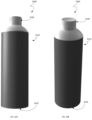
- FIG. 32 A is a side view of a biodegradable container in accordance with an embodiment.
- FIG. 32 B is a side perspective view of the biodegradable container of FIG. 32 A .
- FIG. 32 C is a top perspective view of the biodegradable container of FIG. 32 A .
- FIG. 32 D is a bottom perspective view of the biodegradable container of FIG. 32 A .
- FIG. 32 E is an alternate bottom perspective view of the biodegradable container of FIG. 32 A .
- FIG. 32 F is a bottom view of the biodegradable container of FIG. 32 A .
- FIG. 32 G is a top view of the biodegradable container of FIG. 32 A .
- FIG. 33 A is a side view of a biodegradable container in accordance with an embodiment.
- FIG. 33 B is a side perspective view of the biodegradable container of FIG. 33 A .
- FIG. 33 C is a top perspective view of the biodegradable container of FIG. 33 A .
- FIG. 33 D is a bottom perspective view of the biodegradable container of FIG. 33 A .
- FIG. 33 E is an alternate bottom perspective view of the biodegradable container of FIG. 33 A .
- FIG. 33 F is a bottom view of the biodegradable container of FIG. 33 A .
- FIG. 33 G is a top view of the biodegradable container of FIG. 33 A .
- biodegradable containers comprising parts selected from the group including a polymeric body element, a spiral-wound paper sleeve disposed to envelop or otherwise cover the polymeric body element, a polymeric top dome element welded to the polymeric body element, a polymeric cap, a tamper-evident seal affixed to the polymeric cap and the polymeric top dome element, an internal seal between and internal rim of the polymeric cap and an inner surface of a neck of the polymeric top element, and an external seal between an outer rim of the polymeric cap and an outer surface of the neck of the polymeric top element.
- the containers described herein can be used for the delivery and/or storage of beverages for human consumption or for the delivery of other materials not for human consumption.
- materials that can be contained include beverages, syrups, concentrates, soaps, inks, gels, solids, and powders.
- the polymeric cap, polymeric top dome element and polymeric body element can be preferably comprised of one type of a fully biodegradable material such as a type of polyhydroxyalkanoate (PHA), e.g., polyhydroxybutyrate (PHB), facilitating full recycling and minimal negative impact on environment.
- PHA polyhydroxyalkanoate
- PHB polyhydroxybutyrate
- these components of the container can be made significantly of one type of similar biodegradable material.
- the polymeric top dome element can be joined to the polymeric body element utilizing, for example, spin welding or sonic welding, or alternative bonding, sealing, or gluing techniques. Fluid can be dispensed from the container by pouring, sucking, squirting, or other means.
- the polymeric body element is designed in the embodiments to enhance strength and rigidity without compromising on aesthetics and ergonomics.
- the polymeric body element can resist side force on the container sufficient to allow the container to be picked up in one hand and the beverage or materials to be dispensed in a controlled fashion.
- a complete biodegradable container assembly may be created by, for example, injection molding a polymeric material into a cylindrical polymeric body element and into a polymeric top dome element.
- the polymeric top dome element may include a dome portion and a cylindrical neck defining an aperture and the cylindrical body element may include a plurality of ribs extending from an external surface.
- a lower lip of the dome portion may be spin welded to an upper lip of the cylindrical polymeric body element.
- the dome portion may include indentations for receiving tooling configured to spin the top dome element relative to the cylindrical body element. Other tooling may engage the plurality of ribs of the cylindrical body element in order to render it stationary relative to the top dome element.
- a spiral-wound paper sleeve may be slid onto the cylindrical polymeric body element such that it is supported by the plurality of ribs.
- the container may include a polymeric cap having a threaded internal rim circumscribed by an external cap cover.
- the threaded internal rim is received by a threaded internal surface of the cylindrical neck.
- the external cap cover covers an external surface of the cylindrical neck.
- a tamper-evident label may be affixed to an exterior surface of the cylindrical neck and to an exterior surface of the external cap cover.
- a grade of PHA that is not compounded is utilized so that injection-molding (IM) grades can be pure.
- IM injection-molding
- the walls of the polymeric body element may be of 0.5 draft internally is minimum to maximize volume in straight shape.
- FIGS. 1 A and 1 B are side and longitudinal sectional views, respectively, of an assembled biodegradable container 100 in accordance with an embodiment.
- the biodegradable container 100 includes a polymeric body element 104 covered by a paper sleeve 106 , a polymeric top dome element 110 welded to the polymeric body element 104 , a polymeric cap 114 , and a tamper-evident label 118 in accordance with an embodiment.
- the tamper-evident label 118 does not extend completely around the circumference of the container 100 ; however, in other embodiment the label 118 may completely encircle the container 100 .
- FIG. 1 C is a perspective view of the biodegradable container of FIG. 1 A .
- FIG. 1 D is perspective view of the biodegradable container of FIG. 1 A in an inverted orientation.
- FIG. 1 E is a top view of the container of FIG. 1 A .
- FIG. 1 F is a bottom view of the container of FIG. 1 A.
- FIG. 1 G is a sectional view along a transverse axis of the biodegradable container of FIG. 1 A .
- FIGS. 2 A and 2 B are views of opposite sides of the biodegradable container 100 of FIG. 1 A .
- FIGS. 2 A and 2 B are relatively rotated about a longitudinal axis of the container 100 so as to depict different views of the tamper-evident seal 118 .
- FIGS. 3 A- 3 D are alternate perspective views of the biodegradable container 100 of FIG. 1 A which provide various other views of the tamper-evident seal 118 affixed to the container 100 .
- FIGS. 4 A- 4 B are alternate perspective views of the biodegradable container 100 of FIG. 1 A in an inverted orientation which depict an implementation of the tamper-evident seal 118 from different perspectives.
- FIG. 5 A is another side view of an assembled biodegradable container comprising a polymeric body element covered by a paper sleeve, a polymeric top dome element welded to the polymeric body element, a polymeric cap, and a tamper-evident seal in accordance with an embodiment.
- FIG. 5 B is a bottom view of the container of FIG. 5 A illustrating the manner in which a plurality of external ribs of the polymeric body unit provide support for the paper sleeve.
- FIG. 5 C is a transverse sectional view of the container of FIG. 5 A illustrating the manner in which the plurality of external ribs of the polymeric body unit provide support for the paper sleeve.
- FIG. 5 D is a bottom perspective view of the container of FIG. 5 A .
- FIG. 6 is a perspective exploded view diagram of a biodegradable container 600 comprising a polymeric body element 604 , a paper sleeve 608 disposed to cover the polymeric body element 604 , a polymeric top dome element 610 configured to be welded to the polymeric body element 604 , a polymeric cap 614 , and a tamper-evident label 618 in accordance with an embodiment.
- FIGS. 7 A- 7 F illustrate an embodiment of the top dome element 610 in greater detail.
- FIG. 7 A is a side view of the polymeric top dome element 610 ;
- FIG. 7 B is a sectional view along a longitudinal axis of the top dome element 610 ;
- FIG. 7 C is a top perspective view of the top dome element 610 ;
- FIG. 7 D is a perspective view of the top dome element 610 in an inverted orientation;
- FIG. 7 E is a top view of the top dome element 610 ; and
- FIG. 7 F is a bottom view of the top dome element 610 .
- the top dome element 610 includes a cylindrical neck 704 and a dome portion 708 .
- the wall thickness of the tope dome element 610 is made to be relatively thin in order to aid in its biodegradation.
- An external surface 710 of the cylindrical neck 704 forms a sealing face configured to be substantially flush with an inner surface of an external cover of the cap 614 ( FIGS. 10 A- 10 F ).
- An internal surface 712 of the cylindrical neck 704 defines a tri-start internal thread 716 configured to engage a thread defined by an inner rim of the cap 614 ( FIGS. 10 A- 10 F ).
- a sealing rim 724 is designed to prevent contaminates from entering an interior of the container 600 .
- an optional inner rim 728 contains welding flash.
- a split line 732 may be defined on a top lip of the cylindrical neck 704 .
- FIGS. 8 A- 8 E illustrate additional details of an embodiment of the top dome element 610 .
- a dome rim of the dome portion 808 may define a set of indentations 840 or other recesses configured to be engaged by tooling used in spin welding of the top dome element 610 and the polymeric body element 604 .
- These indentations 840 may match teeth in the spin weld tooling in order to transmit torque into the weld joint.
- the indentations 840 or other recesses are made to be relatively small to improve aesthetics of the container 600 (e.g., to enable the indentations 840 to be hidden by the tamper-evident label 618 ) and to minimize detrimental effects on sealing or adhesion of the label 618 to the top dome element 610 .
- the top dome element 610 and body element 604 are injection molded using a material such as a form of PHA.
- a material such as a form of PHA.
- the walls of the top dome element 610 to the body element 604 are very thin and essentially all available thickness of each is used in spin welding the parts together.
- the optional internal rim 728 keeps the flash in check.
- the top dome element 610 to the body element 604 could be sonic welded are alternatively welded or otherwise joined together.
- FIGS. 9 A- 9 F provide various views of the polymeric body element 604 .
- FIG. 9 A is a side view of a polymeric body element 604 ;
- FIG. 9 B is a sectional view along a longitudinal axis of the polymeric body element 604 ;
- FIG. 9 C is a top perspective view of the polymeric body element 604 ;
- FIG. 9 D is a perspective view of the polymeric body element 604 in an inverted orientation;
- FIG. 9 E is a top view of the polymeric body element 604 ; and
- FIG. 9 F is a bottom view of the polymeric body element 604 .
- the polymeric body element 604 includes a plurality of external ribs 910 supported by a main body 920 . It has been found that the external ribs 910 facilitate in-mold material flow in the injection molding process and provide support for the spiral-wound paper sleeve 608 .
- One or more of the ribs 910 may also include a barbed section to retain the paper sleeve 608 in a fixed position once it has been slide over the ribs 910 .
- each of the external ribs 910 has a rounded end shape that allows for zero draft in a longitudinal direction, which facilitates the molding process.
- the external ribs 910 may be engaged by tooling to hold or otherwise maintain the polymeric body element in as fixed position during the spin molding process as the top dome element 610 is rotated.
- the main body 920 will preferably have relatively thin walls to aid in biodegradation and will preferably be formed through a line-of-draw injection molding process. In one embodiment the nominal draft of walls of the main body is 0.5°.
- FIGS. 10 A- 10 F provide various views of the polymeric cap 614 .
- FIG. 10 A is a side view of the polymeric cap 614 ;
- FIG. 10 B is a sectional view along a longitudinal axis of the polymeric cap 614 ;
- FIG. 10 C is a top perspective view of the polymeric cap of 614 ;
- FIG. 10 D is a perspective view of the polymeric cap 614 in an inverted orientation;
- FIG. 10 E is a top view of the polymeric cap 614 ;
- FIG. 10 F is a bottom view of the polymeric cap 614 .
- the cap 614 includes an internal rim 1010 which defines a hidden tri-start thread 1014 and an external cover 1020 .
- the thread 1014 engages the tri-start internal thread 716 of the neck 704 .
- an inner surface 1024 of the cover 1020 covers the external surface 710 of the cylindrical neck 704 .
- the external cover 1020 also defines a plurality of recesses 1030 , i.e., sections of reduced wall thickness. These reduced-thickness recesses 1030 aid in biodegradation and provide a grip for opening and closing the container 600 using the cap 614 .
- a nominal wall thickness within the recesses 1030 is 0.75 mm with a nominal draft of 0.5°.
- the cap 614 seals on the internal rim 1010 below the thread 1014 .
- This enables the liquid contents of the container 600 to be pressurized (e.g., even still water may have nitrogen added to slightly “pump up” the container 600 or otherwise better enable to maintain its shape in the event of substantial impacts or external pressure.
- An external seal 1040 may also be present at a base 1042 of the cap 614 to keep a drinking surface (e.g., external surface 710 ) of the container 600 clean from contaminants.
- FIGS. 11 A- 11 D provide various views of the spiral-wound paper sleeve.
- FIG. 12 A is a side view of the polymeric body element 604 together with a perspective view of tooling 1210 configured to engage the external ribs 910 of the polymeric body element 604 during a spin welding operation.
- the tooling 1210 includes tool grooves 1220 for engaging the ribs 910 so as to prevent rotation of the body element 604 during spin welding.
- FIG. 12 B shows a partially cutaway perspective view of the tooling 1210 when engaging the polymeric body element 604 .
- FIGS. 13 and 14 illustrate the top dome element 610 and tooling 1310 for rotating the top dome element 610 during spin welding of the top dome element 610 and the body element 604 .
- recesses 840 defined by a rim of the top dome element 610 are configured to be engaged by teeth 1320 of the tooling 1310 to prevent slippage during the spin welding process.
- top tooling 1310 and the bottom tooling 1210 respectively engaging the top dome element 610 and the body element 604 in connection with spin welding of these elements.
- the top tooling 1310 is configured for rotation and the bottom tooling 1210 is configured to hold the body element 604 in a fixed, non-rotating position.
- top tooling 1310 engages the top dome element 610 before pressing the top dome element 610 into contact with the body element 604 ( FIG. 15 B ) and initiating spin welding. At this point a weld is formed by friction of the materials of the spinning top dome element 604 and fixed body element 604 .
- FIGS. 19 A and 19 B are sectional views of the biodegradable container 600 when empty and filled with liquid 1910 , respectively.
- FIG. 20 is a magnified sectional view of an upper portion of the filled biodegradable container 600 ( FIG. 19 B ) with the cap 614 received by the cylindrical neck 704 of the top dome element 610 .
- FIGS. 21 A and 21 B are partially disassembled and assembled perspective views, respectively, of a biodegradable container 2100 in accordance with the disclosure.
- the container 2100 includes a polymeric top dome element 2104 spin welded to a ribbed polymeric body element 2108 .
- a polymeric cap 2112 engages with an internally-threaded neck portion 2120 of the top dome element 2104 .
- the polymeric top dome element 2104 , ribbed polymeric body element 2108 and polymeric cap 2112 are substantially identical to the top dome element 610 , body element 604 and cap 614 of FIG. 6 and the container 2100 may be formed through the spin welding process described above.
- FIGS. 22 A and 22 B are side and sectional views, respectively, of the polymeric top dome element 2104 and the cap 2112 .
- a rim of the top dome element 2104 defines an indentation 2210 for engaging tooling used during the process of spin welding the top dome element to the ribbed polymeric body element 2108 .
- FIGS. 23 - 24 illustrate stages in a process of inserting the biodegradable container 2100 into a spiral wound paper sleeve 2310 .
- the container 2100 is first placed in axial alignment with the sleeve 2310 and then inserted through an end of the sleeve 2310 .
- the sleeve 2310 is then pushed upward against the ribs 2110 .
- One or more of the ribs 2110 may define barbs 2410 for retaining the sleeve 2310 in place once its leading edge has been pushed to proximate a top end 2420 of the body element 2108 , thereby yielding covered container 2100 ′ ( FIG. 23 C ).
- FIGS. 25 A and 25 B are perspective views of the container 2100 after having been partially and completely, respectively, sealed with a tamper-evident label 2510 designed to function as a security seal.
- the diameter of the cap 2112 and the diameter of the neck 2120 of the top dome element 2104 are substantially equal, allowing for the label 2510 to be placed across the joint between these elements.
- the label 2510 may be perforated or otherwise segmented across a midline so that it shears along such perforations when the cap 2112 is removed. Any adhesive added to the side of the label 2510 affixed to the container 2100 ′ may be applied such that is not present over the joint between the cap 2112 and the neck 2120 .
- the label 2510 can be applied easily by a rotational machine.
- FIGS. 26 A- 26 D illustrate different versions of the tamper-evident label 2510 .
- FIG. 26 E illustrates an upper portion of the biodegradable container 2100 ′ with the tamper-evident label 2510 attached.
- FIGS. 27 - 31 illustrate a biodegradable container 2700 having a unitary polymeric body element designed to be manufactured simply and inexpensively.
- FIG. 27 A is an exploded perspective view of an embodiment of the biodegradable container 2700 .
- the embodiment of the biodegradable container comprises a unitary polymeric body element 2710 , a bottom element 2720 and a polymeric cap 2730 in accordance with an embodiment.
- FIG. 27 B is a top perspective view of the unitary polymeric body element 2710 .
- the unitary polymeric body element 2720 includes a polymeric top dome portion 2740 contiguous with a cylindrical body portion 2750 .
- the bottom element 2720 may be welded (e.g., sonic welded) to the cylindrical body portion 2750 of the unitary polymeric body element 2720 .
- the biodegradable container is comprised primarily or exclusively of P-Hydroxy-Benzoate Hydroxylase (PHBH).
- the polymeric top dome portion 2740 includes a cylindrical neck 2742 and a dome portion 2744 .
- the wall thickness of the tope dome portion 2740 is made to be relatively thin in order to aid in its biodegradation.
- An external surface 2746 of the cylindrical neck 2742 forms a sealing face configured to be substantially flush with an inner surface of an external cover of the cap 2730 .
- An internal surface 2748 of the cylindrical neck 2742 defines a tri-start internal thread 2752 configured to engage a thread defined by an inner rim of the cap 2730 .
- FIGS. 28 A and 28 B are a side view and a longitudinal sectional view, respectively, of an embodiment of the unitary polymeric body element 2710 .
- FIG. 28 C is a top view of the embodiment of the unitary polymeric body element 2710 of FIG. 28 A .
- FIGS. 29 A- 29 F and 31 A- 31 H provide various views of the cap 2730 included within the biodegradable container 2700 .
- FIG. 29 A is a top view of the cap 2730 .
- FIG. 29 B is a top perspective view of the cap 2730 .
- FIG. 29 C is a bottom perspective view of the cap 2730 .
- FIG. 29 D is a partially cutaway side view of a first embodiment of the cap 27301 .
- FIG. 29 E is a partially cutaway side view of a second embodiment of the cap 27302 having a tapered sealing face.
- FIG. 29 F is a bottom view of the cap 2730 .
- FIG. 31 A is a side view of the cap 2730 .
- FIG. 31 A is a side sectional view of the cap 2730 .
- FIG. 31 C is a magnified view of a portion of the cap 2730 defining tri-start threads 2914 .
- FIG. 31 D is a bottom view of the cap 2730 .
- FIG. 31 E is a bottom view of the cap 2730 .
- FIG. 31 F is a longitudinal sectional view of the second embodiment of the cap 27302 .
- FIG. 31 G is an inverted and partially transparent perspective view of the second embodiment of the cap 27302 .
- FIG. 31 H is a transverse sectional view of the second embodiment of the cap 27302 .
- FIG. 30 A is a side sectional view of an embodiment of the biodegradable container 2700 utilizing the first embodiment of the cap of the cap 27301 .
- the internal rim 2910 of the cap 27301 defines a tri-start thread 2914 .
- the thread 2914 engages the tri-start internal thread 2752 of the neck 2742 .
- an inner surface 2924 of the cover 2920 covers an external surface 2746 of the cylindrical neck 2742 .
- the external cover 2920 also defines a plurality of recesses 2930 , i.e., sections of reduced wall thickness substantially perpendicular to a base 2942 of the cap 27301 . These reduced-thickness recesses 2930 aid in biodegradation and provide a grip for opening and closing the container 2900 using the cap 2720 .
- a nominal wall thickness within the recesses 2930 is 0.75 mm with a nominal draft of 0.5°.
- the cap 2720 seals on the internal rim 2910 below the thread 2752 . This enables the liquid contents of the container 2700 to be pressurized (e.g., even still water may have nitrogen added to slightly “pump up” the container 2700 or otherwise better enable to maintain its shape in the event of substantial impacts or external pressure.
- FIG. 30 B is a side sectional view of an embodiment of the biodegradable container 2700 utilizing the second embodiment of the cap of the cap 27302 .
- an inner surface 2924 ′ of the cover 2920 forms a tapered sealing face that forms an inner seal 2950 with an upper portion of the external surface 2746 of the cylindrical neck 2742 when the cap 27302 is in a closed position.
- This inner seal ensures liquid is retained within the container 2700 and enables the liquid contents of the container 2700 to be pressurized.
- the inner surface 2924 ′ of the cover 2920 forms an outer seal 2960 with a lower portion of the external surface 2746 of the cylindrical neck 2742 when the cap 27302 is in the closed position. The outer seal prevents contaminants from entering the container 2700 .
- the cap 27302 can be made from a simplified injection molding process that does not require tooling to perform an unscrewing function in connection with forming the thread 2914 . Since no unscrewing mechanism or machinery is required to be introduced into the manufacturing process, the thread 2914 can be created by using hot tips to injected the polymer being used along a path defined by tooling along the outer surface of internal rim 2910 . Since in the embodiment of FIG. 30 B sealing is effected by contact between the inner surface 2924 ′ and the surface 2746 of the cylindrical neck 2742 , the thread 2914 can be attenuated and need not form a shelf or other surface to seal with a corresponding thread or other surface defined by the cylindrical neck 2742 .
- FIGS. 32 A- 32 G are various external views of a biodegradable container 3200 in accordance with the disclosure.
- the biodegradable container 3200 includes a unitary polymeric body element 3210 , a bottom element 3220 and a polymeric cap 3230 in accordance with an embodiment.
- FIG. 32 A is a side view of the biodegradable container 3200 ;
- FIG. 32 B is a side perspective view of the biodegradable container 3200 ;
- FIG. 32 C is a top perspective view of the biodegradable container 3200 ;
- FIG. 32 D is a bottom perspective view of the biodegradable container 3200 ;
- FIG. 32 E is an alternate bottom perspective view of the biodegradable container 3200 ;
- FIG. 32 F is a bottom view of the container 3200 ; and
- FIG. 32 G is a top view of the biodegradable container 3200 .
- FIGS. 33 A- 33 G are various external views of a biodegradable container 3300 in accordance with the disclosure.
- the biodegradable container 3300 includes a unitary polymeric body element 3310 and a bottom element 3320 .
- the unitary polymeric body element 3310 defines a neck portion 3330 having internal threads 3340 configured to receive a polymeric cap (not shown).
- FIG. 33 A is a side view of the biodegradable container 3300 ;
- FIG. 33 B is a side perspective view of the biodegradable container 3300 ;
- FIG. 33 C is a top perspective view of the biodegradable container 3300 ;
- FIG. 33 D is a bottom perspective view of the biodegradable container 3300 ;
- FIG. 33 E is an alternate bottom perspective view of the biodegradable container 3300 ;
- FIG. 33 F is a bottom view of the container 3300 ; and
- FIG. 33 G is a top view of the biodegradable container 3300 .
- inventive concepts may be embodied as one or more methods, of which an example has been provided.
- the acts performed as part of the method may be ordered in any suitable way. Accordingly, embodiments may be constructed in which acts are performed in an order different than illustrated, which may include performing some acts simultaneously, even though shown as sequential acts in illustrative embodiments.
- a reference to “A and/or B”, when used in conjunction with open-ended language such as “comprising” can refer, in one embodiment, to A only (optionally including elements other than B); in another embodiment, to B only (optionally including elements other than A); in yet another embodiment, to both A and B (optionally including other elements); etc.
- the phrase “at least one,” in reference to a list of one or more elements, should be understood to mean at least one element selected from any one or more of the elements in the list of elements, but not necessarily including at least one of each and every element specifically listed within the list of elements and not excluding any combinations of elements in the list of elements.
- This definition also allows that elements may optionally be present other than the elements specifically identified within the list of elements to which the phrase “at least one” refers, whether related or unrelated to those elements specifically identified.
- “at least one of A and B” can refer, in one embodiment, to at least one, optionally including more than one, A, with no B present (and optionally including elements other than B); in another embodiment, to at least one, optionally including more than one, B, with no A present (and optionally including elements other than A); in yet another embodiment, to at least one, optionally including more than one, A, and at least one, optionally including more than one, B (and optionally including other elements); etc.
Landscapes
- Engineering & Computer Science (AREA)
- Mechanical Engineering (AREA)
- Life Sciences & Earth Sciences (AREA)
- Biodiversity & Conservation Biology (AREA)
- Manufacturing & Machinery (AREA)
- Closures For Containers (AREA)
Abstract
Description
Claims (14)
Priority Applications (3)
| Application Number | Priority Date | Filing Date | Title |
|---|---|---|---|
| US16/262,847 US11878849B2 (en) | 2018-04-11 | 2019-01-30 | Injection molded polymeric biodegradable container |
| US17/047,039 US20210147130A1 (en) | 2018-04-11 | 2019-04-11 | Injection molded polymeric biodegradable container |
| PCT/US2019/027091 WO2019200173A1 (en) | 2018-04-11 | 2019-04-11 | Injection molded polymeric biodegradable container |
Applications Claiming Priority (3)
| Application Number | Priority Date | Filing Date | Title |
|---|---|---|---|
| US201862656253P | 2018-04-11 | 2018-04-11 | |
| US201862699532P | 2018-07-17 | 2018-07-17 | |
| US16/262,847 US11878849B2 (en) | 2018-04-11 | 2019-01-30 | Injection molded polymeric biodegradable container |
Related Child Applications (1)
| Application Number | Title | Priority Date | Filing Date |
|---|---|---|---|
| US17/047,039 Continuation US20210147130A1 (en) | 2018-04-11 | 2019-04-11 | Injection molded polymeric biodegradable container |
Publications (2)
| Publication Number | Publication Date |
|---|---|
| US20190329950A1 US20190329950A1 (en) | 2019-10-31 |
| US11878849B2 true US11878849B2 (en) | 2024-01-23 |
Family
ID=68162981
Family Applications (2)
| Application Number | Title | Priority Date | Filing Date |
|---|---|---|---|
| US16/262,847 Active 2039-05-05 US11878849B2 (en) | 2018-04-11 | 2019-01-30 | Injection molded polymeric biodegradable container |
| US17/047,039 Abandoned US20210147130A1 (en) | 2018-04-11 | 2019-04-11 | Injection molded polymeric biodegradable container |
Family Applications After (1)
| Application Number | Title | Priority Date | Filing Date |
|---|---|---|---|
| US17/047,039 Abandoned US20210147130A1 (en) | 2018-04-11 | 2019-04-11 | Injection molded polymeric biodegradable container |
Country Status (2)
| Country | Link |
|---|---|
| US (2) | US11878849B2 (en) |
| WO (1) | WO2019200173A1 (en) |
Cited By (1)
| Publication number | Priority date | Publication date | Assignee | Title |
|---|---|---|---|---|
| USD1096430S1 (en) * | 2022-12-01 | 2025-10-07 | Amorepacific Corporation | Cosmetic container |
Families Citing this family (4)
| Publication number | Priority date | Publication date | Assignee | Title |
|---|---|---|---|---|
| US12521221B2 (en) * | 2018-02-26 | 2026-01-13 | Argenta Innovation Limited | Intra-ruminal device |
| US11878849B2 (en) | 2018-04-11 | 2024-01-23 | Cove, PBC | Injection molded polymeric biodegradable container |
| WO2025090580A1 (en) * | 2023-10-24 | 2025-05-01 | Totterman Alex | Multi component container |
| WO2025166843A1 (en) * | 2024-02-07 | 2025-08-14 | 湖南千山制药机械股份有限公司 | Beverage bottle having high barrier property |
Citations (15)
| Publication number | Priority date | Publication date | Assignee | Title |
|---|---|---|---|---|
| US4140235A (en) * | 1976-07-15 | 1979-02-20 | Tetra Pak Developpement Sa | Closing arrangement for packing containers |
| GB2050320A (en) * | 1979-05-29 | 1981-01-07 | Stayne Products Sa | Closure for container |
| US5465856A (en) | 1993-07-01 | 1995-11-14 | Brent River Packaging Corporation | Plastic container having injection-molded container components |
| US5904259A (en) * | 1996-07-03 | 1999-05-18 | Hidding; Walter E. | Protective tamper-evident label and bottle cap |
| US6315140B1 (en) * | 2000-08-15 | 2001-11-13 | Nadel Industries, Inc. | Bottle/cap assembly with sweep-and-drain action |
| US20040016716A1 (en) | 2001-06-27 | 2004-01-29 | Melrose David M. | Hot-fillable multi-sided blow-molded container |
| JP2007119009A (en) * | 2005-10-28 | 2007-05-17 | Yoshino Kogyosho Co Ltd | Synthetic resin bottle shaped container |
| US20070163213A1 (en) * | 2006-01-19 | 2007-07-19 | Volker Till | Beverage bottling plant for filling beverage bottles with a liquid beverage material and a method of operation thereof |
| US20090250426A1 (en) | 2008-04-04 | 2009-10-08 | Stokely-Van Camp, Inc. | Container Closure With Internal Threading System |
| US20100230405A1 (en) * | 2009-03-11 | 2010-09-16 | Nuvision Bioplastics, Llc | Biodegradable Resin Composition Utilized in the Manufacture of Biodegradable Containers, Biodegradable Containers, and Method of Manufacture |
| US20120181247A1 (en) | 2011-01-14 | 2012-07-19 | 3volve Bioneering LLC | Biodegradable seeded container |
| US20130020277A1 (en) | 2011-07-19 | 2013-01-24 | Lgab Llc | Biodegradable Bottle for Liquids |
| US20140346071A1 (en) | 2011-05-17 | 2014-11-27 | Aktivpak, Inc. | Filing system and methods for aseptic cartridge and dispenser arrangement |
| US20160176103A1 (en) | 2014-12-18 | 2016-06-23 | GM Global Technology Operations LLC | Spin-welding of polymeric components having large surface area or non-complementary weld interfaces |
| US20210147130A1 (en) | 2018-04-11 | 2021-05-20 | Cove, PBC | Injection molded polymeric biodegradable container |
-
2019
- 2019-01-30 US US16/262,847 patent/US11878849B2/en active Active
- 2019-04-11 US US17/047,039 patent/US20210147130A1/en not_active Abandoned
- 2019-04-11 WO PCT/US2019/027091 patent/WO2019200173A1/en not_active Ceased
Patent Citations (16)
| Publication number | Priority date | Publication date | Assignee | Title |
|---|---|---|---|---|
| US4140235A (en) * | 1976-07-15 | 1979-02-20 | Tetra Pak Developpement Sa | Closing arrangement for packing containers |
| GB2050320A (en) * | 1979-05-29 | 1981-01-07 | Stayne Products Sa | Closure for container |
| US5465856A (en) | 1993-07-01 | 1995-11-14 | Brent River Packaging Corporation | Plastic container having injection-molded container components |
| US5904259A (en) * | 1996-07-03 | 1999-05-18 | Hidding; Walter E. | Protective tamper-evident label and bottle cap |
| US6315140B1 (en) * | 2000-08-15 | 2001-11-13 | Nadel Industries, Inc. | Bottle/cap assembly with sweep-and-drain action |
| US20040016716A1 (en) | 2001-06-27 | 2004-01-29 | Melrose David M. | Hot-fillable multi-sided blow-molded container |
| JP2007119009A (en) * | 2005-10-28 | 2007-05-17 | Yoshino Kogyosho Co Ltd | Synthetic resin bottle shaped container |
| US20070163213A1 (en) * | 2006-01-19 | 2007-07-19 | Volker Till | Beverage bottling plant for filling beverage bottles with a liquid beverage material and a method of operation thereof |
| US20090250426A1 (en) | 2008-04-04 | 2009-10-08 | Stokely-Van Camp, Inc. | Container Closure With Internal Threading System |
| US7980403B2 (en) * | 2008-04-04 | 2011-07-19 | Stokely-Van Camp, Inc. | Container closure with internal threading system |
| US20100230405A1 (en) * | 2009-03-11 | 2010-09-16 | Nuvision Bioplastics, Llc | Biodegradable Resin Composition Utilized in the Manufacture of Biodegradable Containers, Biodegradable Containers, and Method of Manufacture |
| US20120181247A1 (en) | 2011-01-14 | 2012-07-19 | 3volve Bioneering LLC | Biodegradable seeded container |
| US20140346071A1 (en) | 2011-05-17 | 2014-11-27 | Aktivpak, Inc. | Filing system and methods for aseptic cartridge and dispenser arrangement |
| US20130020277A1 (en) | 2011-07-19 | 2013-01-24 | Lgab Llc | Biodegradable Bottle for Liquids |
| US20160176103A1 (en) | 2014-12-18 | 2016-06-23 | GM Global Technology Operations LLC | Spin-welding of polymeric components having large surface area or non-complementary weld interfaces |
| US20210147130A1 (en) | 2018-04-11 | 2021-05-20 | Cove, PBC | Injection molded polymeric biodegradable container |
Non-Patent Citations (3)
| Title |
|---|
| International Search Report dated Aug. 7, 2019, for PCT Application No. PCT/US2019/027091, filed on Apr. 11, 2019, 4 pages. |
| Non-Final Office Action dated Feb. 22, 2023, for U.S. Appl. No. 17/047,039, filed Oct. 12, 2020, 13 pages. |
| Written Opinion of the International Searching Authority dated Aug. 7, 2019, for PCT Application No. PCT/US2019/027091, filed on Apr. 11, 2019, 8 pages. |
Cited By (1)
| Publication number | Priority date | Publication date | Assignee | Title |
|---|---|---|---|---|
| USD1096430S1 (en) * | 2022-12-01 | 2025-10-07 | Amorepacific Corporation | Cosmetic container |
Also Published As
| Publication number | Publication date |
|---|---|
| US20190329950A1 (en) | 2019-10-31 |
| US20210147130A1 (en) | 2021-05-20 |
| WO2019200173A1 (en) | 2019-10-17 |
Similar Documents
| Publication | Publication Date | Title |
|---|---|---|
| US11878849B2 (en) | Injection molded polymeric biodegradable container | |
| US12071293B2 (en) | Containers for holding materials | |
| US9452857B2 (en) | Containers for holding materials | |
| AU2006321010B2 (en) | System and method for distribution and dispensing of beverages | |
| US8430262B2 (en) | Containers for holding materials | |
| US20120248117A1 (en) | Re-usable carafe system with re-closable pouches | |
| US20240391666A1 (en) | Nested stack of capped beverage containers | |
| US20130193020A1 (en) | Re-Usable Carafe System with Re-Closable Pouches | |
| US20150238988A1 (en) | Fitment for polymeric bag within fiber shell container | |
| US20240359895A1 (en) | Containers for holding materials | |
| JPH1095440A (en) | Plastic bag | |
| KR200305497Y1 (en) | drinking water bottle | |
| KR100503278B1 (en) | drinking water bottle | |
| HK1081909A (en) | Improved dispensing package |
Legal Events
| Date | Code | Title | Description |
|---|---|---|---|
| FEPP | Fee payment procedure |
Free format text: ENTITY STATUS SET TO UNDISCOUNTED (ORIGINAL EVENT CODE: BIG.); ENTITY STATUS OF PATENT OWNER: SMALL ENTITY |
|
| FEPP | Fee payment procedure |
Free format text: ENTITY STATUS SET TO SMALL (ORIGINAL EVENT CODE: SMAL); ENTITY STATUS OF PATENT OWNER: SMALL ENTITY |
|
| STPP | Information on status: patent application and granting procedure in general |
Free format text: APPLICATION DISPATCHED FROM PREEXAM, NOT YET DOCKETED |
|
| AS | Assignment |
Owner name: COVE, PBC, CALIFORNIA Free format text: ASSIGNMENT OF ASSIGNORS INTEREST;ASSIGNORS:TOTTERMAN, ALEX;WHITE, MATTHEW;SIGNING DATES FROM 20190415 TO 20190416;REEL/FRAME:051250/0616 |
|
| STPP | Information on status: patent application and granting procedure in general |
Free format text: DOCKETED NEW CASE - READY FOR EXAMINATION |
|
| STPP | Information on status: patent application and granting procedure in general |
Free format text: NON FINAL ACTION MAILED |
|
| STPP | Information on status: patent application and granting procedure in general |
Free format text: RESPONSE TO NON-FINAL OFFICE ACTION ENTERED AND FORWARDED TO EXAMINER |
|
| STPP | Information on status: patent application and granting procedure in general |
Free format text: FINAL REJECTION MAILED |
|
| STPP | Information on status: patent application and granting procedure in general |
Free format text: DOCKETED NEW CASE - READY FOR EXAMINATION |
|
| STPP | Information on status: patent application and granting procedure in general |
Free format text: NON FINAL ACTION MAILED |
|
| AS | Assignment |
Owner name: SILICON VALLEY BANK, CALIFORNIA Free format text: SECURITY INTEREST;ASSIGNOR:COVE, PBC;REEL/FRAME:062802/0060 Effective date: 20230224 |
|
| AS | Assignment |
Owner name: TOTTERMAN, ALEX, CALIFORNIA Free format text: SECURITY INTEREST;ASSIGNOR:COVE, PBC;REEL/FRAME:063062/0028 Effective date: 20230224 Owner name: JAM FUND 2, L.P., CALIFORNIA Free format text: SECURITY INTEREST;ASSIGNOR:COVE, PBC;REEL/FRAME:063062/0028 Effective date: 20230224 Owner name: LITANI HOLDINGS, LLC, FLORIDA Free format text: SECURITY INTEREST;ASSIGNOR:COVE, PBC;REEL/FRAME:063062/0028 Effective date: 20230224 Owner name: VSV COVE HOLDINGS L.P., ILLINOIS Free format text: SECURITY INTEREST;ASSIGNOR:COVE, PBC;REEL/FRAME:063062/0028 Effective date: 20230224 |
|
| STPP | Information on status: patent application and granting procedure in general |
Free format text: RESPONSE TO NON-FINAL OFFICE ACTION ENTERED AND FORWARDED TO EXAMINER |
|
| AS | Assignment |
Owner name: VSV COVE HOLDINGS L.P., ILLINOIS Free format text: SECURITY INTEREST;ASSIGNOR:COVE, PBC;REEL/FRAME:063837/0047 Effective date: 20230523 |
|
| AS | Assignment |
Owner name: COVE, PBC, CALIFORNIA Free format text: RELEASE BY SECURED PARTY;ASSIGNOR:FIRST-CITIZENS BANK & TRUST COMPANY (SUCCESSOR BY PURCHASE TO THE FEDERAL DEPOSIT INSURANCE CORPORATION AS RECEIVER FOR SILICON VALLEY BRIDGE BANK, N.A. (AS SUCCESSOR TO SILICON VALLEY BANK);REEL/FRAME:064094/0611 Effective date: 20230627 |
|
| STPP | Information on status: patent application and granting procedure in general |
Free format text: NOTICE OF ALLOWANCE MAILED -- APPLICATION RECEIVED IN OFFICE OF PUBLICATIONS |
|
| AS | Assignment |
Owner name: COVE, PBC, CALIFORNIA Free format text: RELEASE BY SECURED PARTY;ASSIGNORS:VSV COVE HOLDINGS L.P.;LITANI HOLDINGS, LLC;JAM FUND 2, L.P.;AND OTHERS;REEL/FRAME:065292/0893 Effective date: 20231019 |
|
| STPP | Information on status: patent application and granting procedure in general |
Free format text: DOCKETED NEW CASE - READY FOR EXAMINATION |
|
| STPP | Information on status: patent application and granting procedure in general |
Free format text: NOTICE OF ALLOWANCE MAILED -- APPLICATION RECEIVED IN OFFICE OF PUBLICATIONS |
|
| STPP | Information on status: patent application and granting procedure in general |
Free format text: PUBLICATIONS -- ISSUE FEE PAYMENT RECEIVED |
|
| STPP | Information on status: patent application and granting procedure in general |
Free format text: PUBLICATIONS -- ISSUE FEE PAYMENT VERIFIED |
|
| STCF | Information on status: patent grant |
Free format text: PATENTED CASE |