US11876320B2 - Hinged seal cap - Google Patents
Hinged seal cap Download PDFInfo
- Publication number
- US11876320B2 US11876320B2 US17/587,426 US202217587426A US11876320B2 US 11876320 B2 US11876320 B2 US 11876320B2 US 202217587426 A US202217587426 A US 202217587426A US 11876320 B2 US11876320 B2 US 11876320B2
- Authority
- US
- United States
- Prior art keywords
- cable
- cap
- seal
- openings
- cable receiving
- Prior art date
- Legal status (The legal status is an assumption and is not a legal conclusion. Google has not performed a legal analysis and makes no representation as to the accuracy of the status listed.)
- Active
Links
Images


Classifications
-
- H—ELECTRICITY
- H01—ELECTRIC ELEMENTS
- H01R—ELECTRICALLY-CONDUCTIVE CONNECTIONS; STRUCTURAL ASSOCIATIONS OF A PLURALITY OF MUTUALLY-INSULATED ELECTRICAL CONNECTING ELEMENTS; COUPLING DEVICES; CURRENT COLLECTORS
- H01R13/00—Details of coupling devices of the kinds covered by groups H01R12/70 or H01R24/00 - H01R33/00
- H01R13/46—Bases; Cases
- H01R13/50—Bases; Cases formed as an integral body
- H01R13/501—Bases; Cases formed as an integral body comprising an integral hinge or a frangible part
-
- H—ELECTRICITY
- H01—ELECTRIC ELEMENTS
- H01R—ELECTRICALLY-CONDUCTIVE CONNECTIONS; STRUCTURAL ASSOCIATIONS OF A PLURALITY OF MUTUALLY-INSULATED ELECTRICAL CONNECTING ELEMENTS; COUPLING DEVICES; CURRENT COLLECTORS
- H01R13/00—Details of coupling devices of the kinds covered by groups H01R12/70 or H01R24/00 - H01R33/00
- H01R13/46—Bases; Cases
- H01R13/52—Dustproof, splashproof, drip-proof, waterproof, or flameproof cases
- H01R13/5219—Sealing means between coupling parts, e.g. interfacial seal
- H01R13/5221—Sealing means between coupling parts, e.g. interfacial seal having cable sealing means
-
- H—ELECTRICITY
- H01—ELECTRIC ELEMENTS
- H01R—ELECTRICALLY-CONDUCTIVE CONNECTIONS; STRUCTURAL ASSOCIATIONS OF A PLURALITY OF MUTUALLY-INSULATED ELECTRICAL CONNECTING ELEMENTS; COUPLING DEVICES; CURRENT COLLECTORS
- H01R13/00—Details of coupling devices of the kinds covered by groups H01R12/70 or H01R24/00 - H01R33/00
- H01R13/46—Bases; Cases
- H01R13/52—Dustproof, splashproof, drip-proof, waterproof, or flameproof cases
- H01R13/5205—Sealing means between cable and housing, e.g. grommet
- H01R13/5208—Sealing means between cable and housing, e.g. grommet having at least two cable receiving openings
-
- H—ELECTRICITY
- H01—ELECTRIC ELEMENTS
- H01R—ELECTRICALLY-CONDUCTIVE CONNECTIONS; STRUCTURAL ASSOCIATIONS OF A PLURALITY OF MUTUALLY-INSULATED ELECTRICAL CONNECTING ELEMENTS; COUPLING DEVICES; CURRENT COLLECTORS
- H01R13/00—Details of coupling devices of the kinds covered by groups H01R12/70 or H01R24/00 - H01R33/00
- H01R13/46—Bases; Cases
- H01R13/516—Means for holding or embracing insulating body, e.g. casing, hoods
-
- H—ELECTRICITY
- H01—ELECTRIC ELEMENTS
- H01R—ELECTRICALLY-CONDUCTIVE CONNECTIONS; STRUCTURAL ASSOCIATIONS OF A PLURALITY OF MUTUALLY-INSULATED ELECTRICAL CONNECTING ELEMENTS; COUPLING DEVICES; CURRENT COLLECTORS
- H01R13/00—Details of coupling devices of the kinds covered by groups H01R12/70 or H01R24/00 - H01R33/00
- H01R13/46—Bases; Cases
- H01R13/52—Dustproof, splashproof, drip-proof, waterproof, or flameproof cases
- H01R13/5205—Sealing means between cable and housing, e.g. grommet
-
- H—ELECTRICITY
- H01—ELECTRIC ELEMENTS
- H01R—ELECTRICALLY-CONDUCTIVE CONNECTIONS; STRUCTURAL ASSOCIATIONS OF A PLURALITY OF MUTUALLY-INSULATED ELECTRICAL CONNECTING ELEMENTS; COUPLING DEVICES; CURRENT COLLECTORS
- H01R13/00—Details of coupling devices of the kinds covered by groups H01R12/70 or H01R24/00 - H01R33/00
- H01R13/46—Bases; Cases
- H01R13/52—Dustproof, splashproof, drip-proof, waterproof, or flameproof cases
- H01R13/5213—Covers
Definitions
- the present disclosure relates to electrical connectors, and more specifically, to improved systems for selectively sealing wire openings of an electrical connector, such as a charging receptacle or inlet of an electric vehicle (EV).
- an electrical connector such as a charging receptacle or inlet of an electric vehicle (EV).
- EV electric vehicle
- EVs are increasing in popularity as their practicality and usability improves.
- associated systems and components of these vehicles must be continuously optimized to extract maximum performance, usability and reliability.
- One critical aspect of EV usability includes the ability to consistently charge its batteries as quickly as possible over the life of the vehicle. In this way, it is desired to minimize any degradations in charging performance.
- Charging performance can be affected by any number of factors, including moisture, dirt and other debris contaminating and/or degrading the electrical terminals or contacts of the charger plug or the socket/receptacle of the EV. Thus, it is desired to shield these sensitive surfaces and/or components from the outside environment.
- a cap for an electrical connector comprises a first cap body defining a first portion of a first circular opening, and a second cap body defining a second portion of the first circular opening.
- the second cap body is hingedly connected to the first cap body and is movable between an open position and a closed position. In the closed position, the first and second portions of the first cap body and the second cap body define a circular opening sized to receive a conductive cable therethrough.
- FIG. 1 is a perspective view of an electrical connector and a hinged seal cap in an open position according to an embodiment of the present disclosure
- FIG. 2 is a perspective view of the connector and the hinged seal cap in a closed position capturing a plurality of cables therethrough;
- FIG. 3 is a perspective view of the connector with the hinged seal cap in an installed position thereon;
- FIG. 4 is a side cross-sectional view of the connector with the hinged seal cap in the installed position taken along section A-A of FIG. 3 ;
- FIG. 5 is a top perspective view of the hinged seal cap in the open position
- FIG. 6 is a bottom perspective view of the hinged seal cap in the open position
- FIG. 7 is a top perspective view of the hinged seal cap in the closed position
- FIG. 8 is a bottom perspective view of the hinged seal cap in the closed position
- FIG. 9 is a top view of the hinged seal cap in the closed position
- FIG. 10 is a side view of the hinged seal cap in the closed position.
- FIG. 11 is a bottom view of the hinged seal cap in the closed position.
- a seal cap for an electrical connector comprises a first cap body defining a first portion of a plurality of circular openings, and a second cap body defining a second portion of the plurality of circular openings.
- the second cap body is hingedly connected to the first cap body and movable between an open position and a closed position. In the closed position, first and second portions of the first cap body and the second cap body define the plurality of circular openings, each sized to receive a conductive cable therethrough.
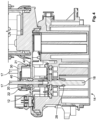
- the exemplary electrical connector 10 includes a housing 12 defining a front opening 14 for receiving a portion of a mating connector or a mating terminal (e.g., a charging plug, not shown) in a mating direction.
- the housing 12 further includes a plurality of rear openings 16 (e.g., five) each receiving a conductive cable or wire 17 and/or an electrical terminal 18 for mating with the corresponding mating connector or terminal, as shown in FIG. 4 . Still referring to FIG.
- the terminal 18 may be crimped onto an end of the cable 17 prior to its insertion into the housing 12 .
- the terminal 18 is installed into the rear opening 16 of the housing 12 in an insertion or installation direction, generally opposite to the mating direction. In this way, the terminal 18 may be described as being “rear-loaded” within the connector housing 12 .
- the housing 12 further defines a terminal latch 28 for engaging with an annual groove of the terminal 18 in an installed position.
- the terminal latch 28 forms a mechanical stop for fixing the insertion distance of the terminal 18 within the housing 12 , as well as preventing its removal.
- An annular cable seal 20 is provided within each rear opening 16 for forming a seal between the cable 17 and an inner face of a protruding wall 22 of the housing 12 defining the rear opening.
- a seal cap 30 is adapted to be selectively secured onto at least one, and in the exemplary embodiment five, cable(s) 17 simultaneously.
- the cap 30 comprises a split body configuration, including first and second cap bodies or portions 31 , 32 which are hingedly connected and movable between an open position as shown in FIG. 1 , and a closed position as shown in FIGS. 2 - 4 .
- Each cap body 31 , 32 defines a portion of a plurality of cable openings. In this way, the cap 30 may be fitted over the cables 17 after their insertion into the exemplary connector 10 , or after the application of other connectorization (e.g., terminals 18 ).
- the cap 30 is secured to the rear of the housing 12 of the connector 10 via corresponding locking features 21 , 42 , such as complementary snap-fit latches 42 and catches 21 .
- a plurality of cylindrical seal retainers 40 defined by the cap 30 are received within the rear openings 16 for holding and/or retaining each of the cable seals 20 within their respective opening.
- the cap 30 provides protection against, for example, dirt, debris and fluid (including high-pressure spray) from entering the connector 10 .
- the cap 30 also provides strain relief for the cables 17 .
- connection 34 comprises a rotating assembly including an axle, such as a pin, and corresponding female portion rotatably receiving the axle.
- connection 34 comprises a hinge, and more specifically, a living hinge formed integrally with the first and second bodies 31 , 32 . As shown in FIG. 7 , in the closed position, the connection or living hinge 34 is elastically deformed into an arcuate shape.
- Each first and second body 31 , 32 further includes a first locking mechanism, such as a latch 36 formed on the first body and a catch 38 formed on the second body.
- the locking features 36 , 38 cooperate to selectively fix the first and second bodies 31 , 32 in the closed position, as shown in FIGS. 7 - 11 .
- a second locking mechanism such as an “L-shaped” cantilevered latch 37 and a catch 39 , are arranged on sides of the first and second bodies 31 , 32 proximate the connection 34 .
- the latch 37 and catch 39 engage in the closed position of the cap 30 for ensuring the first and second bodies 31 , 32 are tightly secured proximate the hinged connection 34 .
- the second locking features or mechanism ensure the functionality of the cap 30 .
- the hinged connection 34 is split into upper and lower halves or portions in order to accommodate the secondary locking features therebetween.
- the first body defines 31 a plurality of cable receiving slots 43 .
- Each cable receiving slot 43 has an end defining a portion of a circle, or a semi-circular lower end 45 .
- the first body 31 defines a plurality of cable retaining protrusions 47 .
- Each cable retaining protrusion 47 defines a portion of a circle, or a semi-circular end 49 .
- each cable slot 43 is arranged between adjacent retaining protrusions 47 .
- the second body 32 defines a plurality of cable receiving slots 53 .
- Each cable receiving slot 53 includes an end defining a portion of a circle, or a semi-circular lower end 55 .
- the second body 32 further defines a plurality of cable retaining protrusions 57 .
- Each cable retaining protrusion 57 defines a portion of a circle, or a semi-circular end 59 .
- Each cable retaining protrusion 57 is arranged between adjacent cable slots 53 .
- the number of cable slots 43 of the first body corresponds to the number of cable retaining protrusions 57 of the second body.
- the number of cable retaining protrusions 47 of the first body 31 corresponds to the number of cable slots 53 of the second body 32 .
- the cable receiving slots 43 , 53 are formed into respective first and second cap bodies 31 , 32 in cable receiving directions.
- each cable retaining protrusion 47 , 57 extends from the cap bodies 31 , 32 in directions opposite to the cable receiving directions.
- the cable retaining protrusions 47 , 57 may be embodied as single-walled, or generally planar, tabs.
- the cable receiving slots 53 define lateral channels 61 on either side of the slots for receiving the lateral ends of each cable receiving protrusion 47 .
- the cable retaining protrusions 57 of the second body 32 define a lower wall of each of the channels 61 . Accordingly, in the closed position, the bodies 31 , 32 are supported against relative axial movement via the engagement of the protrusions 47 within the slots 61 .
- each seal retainer 40 extends at least 270 degrees in a radial direction, and defines a slotted opening 41 in the radial direction sized to accept the cable 17 therethrough.
- the seal retainers 40 extend from the seal cap in a direction toward the connector housing.
- first and second bodies 31 , 32 are joined along a part line P.
- the cable receiving slots 43 of the first body 31 and the cable receiving protrusions 57 of the second body 32 cooperate to define a first plurality of closed circular openings 70 (e.g., two openings), and the cable receiving protrusions 47 of the first body and the cable receiving slots 53 of the second body cooperate to define a second plurality of closed circular openings 72 (e.g., three openings).
- Each seal retainer 40 is coaxially aligned with a respective one of the openings 70 , 72 .
- the openings 70 , 72 are arranged in respective first and second rows across a width of the cap 30 , as shown in FIGS. 9 and 11 .
- Windows or openings 60 may be defined in either or both of the first and second bodies 31 , 32 , and specifically the peripheral wall 33 thereof, to provide visual and/or physical access to captured cables 17 .
- Complementary stiffening ribs 63 may be defined on the outer surfaces of each of the first and second bodies 31 , 32 for strengthening the cap 30 .
- the stiffening ribs 63 of the first and second bodies 31 , 32 may overlap in a width direction with the cap 30 in the closed position, as shown in FIGS. 7 and 9 .
Landscapes
- Connector Housings Or Holding Contact Members (AREA)
Abstract
Description
Claims (20)
Priority Applications (3)
| Application Number | Priority Date | Filing Date | Title |
|---|---|---|---|
| US17/587,426 US11876320B2 (en) | 2021-02-04 | 2022-01-28 | Hinged seal cap |
| DE102022102676.0A DE102022102676A1 (en) | 2021-02-04 | 2022-02-04 | Hinged sealing cap |
| CN202210116372.5A CN114865378A (en) | 2021-02-04 | 2022-02-07 | Hinge sealing cover |
Applications Claiming Priority (2)
| Application Number | Priority Date | Filing Date | Title |
|---|---|---|---|
| US202163145629P | 2021-02-04 | 2021-02-04 | |
| US17/587,426 US11876320B2 (en) | 2021-02-04 | 2022-01-28 | Hinged seal cap |
Publications (2)
| Publication Number | Publication Date |
|---|---|
| US20220247117A1 US20220247117A1 (en) | 2022-08-04 |
| US11876320B2 true US11876320B2 (en) | 2024-01-16 |
Family
ID=82403104
Family Applications (1)
| Application Number | Title | Priority Date | Filing Date |
|---|---|---|---|
| US17/587,426 Active US11876320B2 (en) | 2021-02-04 | 2022-01-28 | Hinged seal cap |
Country Status (3)
| Country | Link |
|---|---|
| US (1) | US11876320B2 (en) |
| CN (1) | CN114865378A (en) |
| DE (1) | DE102022102676A1 (en) |
Families Citing this family (1)
| Publication number | Priority date | Publication date | Assignee | Title |
|---|---|---|---|---|
| CN118801151B (en) * | 2023-04-14 | 2025-11-18 | 锐捷网络股份有限公司 | A terminal block and terminal equipment |
Citations (3)
| Publication number | Priority date | Publication date | Assignee | Title |
|---|---|---|---|---|
| US6331124B1 (en) * | 1999-08-23 | 2001-12-18 | Autonetworks Technologies Ltd. | Waterproof connector |
| US9632268B2 (en) * | 2012-07-02 | 2017-04-25 | CommScope Connectivity Belgium BVBA | Pressure actuated sealant assembly |
| US10116085B1 (en) * | 2018-05-08 | 2018-10-30 | Delphi Technologies, Inc. | Sealed connector with an extended seal sleeve and retainer |
-
2022
- 2022-01-28 US US17/587,426 patent/US11876320B2/en active Active
- 2022-02-04 DE DE102022102676.0A patent/DE102022102676A1/en active Pending
- 2022-02-07 CN CN202210116372.5A patent/CN114865378A/en active Pending
Patent Citations (3)
| Publication number | Priority date | Publication date | Assignee | Title |
|---|---|---|---|---|
| US6331124B1 (en) * | 1999-08-23 | 2001-12-18 | Autonetworks Technologies Ltd. | Waterproof connector |
| US9632268B2 (en) * | 2012-07-02 | 2017-04-25 | CommScope Connectivity Belgium BVBA | Pressure actuated sealant assembly |
| US10116085B1 (en) * | 2018-05-08 | 2018-10-30 | Delphi Technologies, Inc. | Sealed connector with an extended seal sleeve and retainer |
Also Published As
| Publication number | Publication date |
|---|---|
| CN114865378A (en) | 2022-08-05 |
| DE102022102676A1 (en) | 2022-08-04 |
| US20220247117A1 (en) | 2022-08-04 |
Similar Documents
| Publication | Publication Date | Title |
|---|---|---|
| US11590852B2 (en) | Hinged flap cover with angled seal for electric vehicle charging inlet | |
| KR101699576B1 (en) | Electrical connector assembly | |
| US6247965B1 (en) | Electrical connector having sealed snap-in locking cavity plugs | |
| EP0615312B1 (en) | Connector | |
| EP0306635A2 (en) | Electrical connector | |
| EP0292118B1 (en) | Probeable sealed connector in combination with an external probe | |
| US6887106B2 (en) | Shielding connector | |
| US20170069997A1 (en) | Plug and Socket for Electrical Plug-and-Socket Connection | |
| JP6889696B2 (en) | Corrugated tube holder and wire harness | |
| US11876320B2 (en) | Hinged seal cap | |
| WO2012026972A1 (en) | Plug assembly | |
| CN216981048U (en) | Shielding shell for high-voltage connector, connector shell assembly, connector and connector assembly | |
| CN111725651B (en) | Connector with a locking member | |
| US7601028B2 (en) | Housing and electrical plug for transmitting electrical drive power | |
| US10090614B2 (en) | Electrical connector having sealed snap-in locking cavity plugs | |
| US11387595B2 (en) | Connector arrangement with environmental and electrical protection | |
| KR20140125319A (en) | Lever-type connector | |
| CN216720352U (en) | Two-pole socket protection structure and two-pole socket | |
| JP3322141B2 (en) | Connector with wire cover | |
| KR20230145632A (en) | Connector | |
| JP3687468B2 (en) | connector | |
| WO1998020583A1 (en) | Protective cover for electrical connector | |
| CN219477083U (en) | Cable plug connector | |
| JP7428973B2 (en) | connector | |
| US12463381B2 (en) | Hinged connector |
Legal Events
| Date | Code | Title | Description |
|---|---|---|---|
| AS | Assignment |
Owner name: TE CONNECTIVITY SERVICES GMBH, SWITZERLAND Free format text: ASSIGNMENT OF ASSIGNORS INTEREST;ASSIGNORS:RHODES, CLARA;PETERSON, KEVIN JOHN;MOLL, HURLEY CHESTER;SIGNING DATES FROM 20220124 TO 20220128;REEL/FRAME:058811/0159 |
|
| FEPP | Fee payment procedure |
Free format text: ENTITY STATUS SET TO UNDISCOUNTED (ORIGINAL EVENT CODE: BIG.); ENTITY STATUS OF PATENT OWNER: LARGE ENTITY |
|
| STPP | Information on status: patent application and granting procedure in general |
Free format text: DOCKETED NEW CASE - READY FOR EXAMINATION |
|
| AS | Assignment |
Owner name: TE CONNECTIVITY SOLUTIONS GMBH, SWITZERLAND Free format text: MERGER;ASSIGNOR:TE CONNECTIVITY SERVICES GMBH;REEL/FRAME:060305/0923 Effective date: 20220301 |
|
| STPP | Information on status: patent application and granting procedure in general |
Free format text: NON FINAL ACTION MAILED |
|
| STPP | Information on status: patent application and granting procedure in general |
Free format text: RESPONSE TO NON-FINAL OFFICE ACTION ENTERED AND FORWARDED TO EXAMINER |
|
| STPP | Information on status: patent application and granting procedure in general |
Free format text: FINAL REJECTION MAILED |
|
| STPP | Information on status: patent application and granting procedure in general |
Free format text: RESPONSE AFTER FINAL ACTION FORWARDED TO EXAMINER |
|
| STPP | Information on status: patent application and granting procedure in general |
Free format text: NOTICE OF ALLOWANCE MAILED -- APPLICATION RECEIVED IN OFFICE OF PUBLICATIONS |
|
| STPP | Information on status: patent application and granting procedure in general |
Free format text: PUBLICATIONS -- ISSUE FEE PAYMENT VERIFIED |
|
| STCF | Information on status: patent grant |
Free format text: PATENTED CASE |