US11874349B2 - Cross inductor/capacitor to simplify MRI coil element decoupling - Google Patents
Cross inductor/capacitor to simplify MRI coil element decoupling Download PDFInfo
- Publication number
- US11874349B2 US11874349B2 US17/576,107 US202217576107A US11874349B2 US 11874349 B2 US11874349 B2 US 11874349B2 US 202217576107 A US202217576107 A US 202217576107A US 11874349 B2 US11874349 B2 US 11874349B2
- Authority
- US
- United States
- Prior art keywords
- connecting end
- inductor
- capacitor
- coil unit
- phase shift
- Prior art date
- Legal status (The legal status is an assumption and is not a legal conclusion. Google has not performed a legal analysis and makes no representation as to the accuracy of the status listed.)
- Active
Links
Images


Classifications
-
- G—PHYSICS
- G01—MEASURING; TESTING
- G01R—MEASURING ELECTRIC VARIABLES; MEASURING MAGNETIC VARIABLES
- G01R33/00—Arrangements or instruments for measuring magnetic variables
- G01R33/20—Arrangements or instruments for measuring magnetic variables involving magnetic resonance
- G01R33/28—Details of apparatus provided for in groups G01R33/44 - G01R33/64
- G01R33/32—Excitation or detection systems, e.g. using radio frequency signals
- G01R33/36—Electrical details, e.g. matching or coupling of the coil to the receiver
- G01R33/3642—Mutual coupling or decoupling of multiple coils, e.g. decoupling of a receive coil from a transmission coil, or intentional coupling of RF coils, e.g. for RF magnetic field amplification
- G01R33/365—Decoupling of multiple RF coils wherein the multiple RF coils have the same function in MR, e.g. decoupling of a receive coil from another receive coil in a receive coil array, decoupling of a transmission coil from another transmission coil in a transmission coil array
-
- G—PHYSICS
- G01—MEASURING; TESTING
- G01R—MEASURING ELECTRIC VARIABLES; MEASURING MAGNETIC VARIABLES
- G01R33/00—Arrangements or instruments for measuring magnetic variables
- G01R33/20—Arrangements or instruments for measuring magnetic variables involving magnetic resonance
- G01R33/28—Details of apparatus provided for in groups G01R33/44 - G01R33/64
- G01R33/32—Excitation or detection systems, e.g. using radio frequency signals
- G01R33/36—Electrical details, e.g. matching or coupling of the coil to the receiver
- G01R33/3642—Mutual coupling or decoupling of multiple coils, e.g. decoupling of a receive coil from a transmission coil, or intentional coupling of RF coils, e.g. for RF magnetic field amplification
-
- G—PHYSICS
- G01—MEASURING; TESTING
- G01R—MEASURING ELECTRIC VARIABLES; MEASURING MAGNETIC VARIABLES
- G01R33/00—Arrangements or instruments for measuring magnetic variables
- G01R33/20—Arrangements or instruments for measuring magnetic variables involving magnetic resonance
- G01R33/28—Details of apparatus provided for in groups G01R33/44 - G01R33/64
- G01R33/32—Excitation or detection systems, e.g. using radio frequency signals
- G01R33/36—Electrical details, e.g. matching or coupling of the coil to the receiver
- G01R33/3685—Means for reducing sheath currents, e.g. RF traps, baluns
-
- G—PHYSICS
- G01—MEASURING; TESTING
- G01R—MEASURING ELECTRIC VARIABLES; MEASURING MAGNETIC VARIABLES
- G01R33/00—Arrangements or instruments for measuring magnetic variables
- G01R33/20—Arrangements or instruments for measuring magnetic variables involving magnetic resonance
- G01R33/44—Arrangements or instruments for measuring magnetic variables involving magnetic resonance using nuclear magnetic resonance [NMR]
Definitions
- the present disclosure relates to the technical field of magnetic resonance (MR) systems, in particular to a coil unit decoupling device and a magnetic resonance system.
- MR magnetic resonance
- FIG. 1 is a schematic diagram of four coil units distributed on a cylindrical surface, wherein overlapping decoupling can be realized between adjacent coil units, for example, between coil units 11 and 12 , between coil units 11 and 14 , between coil units 12 and 13 , and between coil units 13 and 14 , but it is difficult to realize decoupling between coil units 11 and 13 and between coil units 12 and 14 because the coil units 11 and 13 are not adjacent to each other and the coil units 12 and 14 are not adjacent to each other.
- aspects of the present disclosure provide coil unit decoupling devices to lower the complexity in decoupling coil units in an MR system.
- aspects of the present disclosure further provide MR systems to lower the complexity in decoupling the coil units in the MR systems.
- a coil unit decoupling device comprises a first phase shift circuit, a second phase shift circuit and a first crossover element, and the first crossover element is a capacitor or inductor, wherein
- the first phase shift circuit comprises a first capacitor and a first inductor group, and the first inductor group comprises one inductor or multiple inductors connected in series, wherein
- the device further comprises at least one crossover element, the at least one crossover element being a capacitor or inductor, wherein a first connecting end of each crossover element of the at least one crossover element is connected with any connecting end of any inductor in the first inductor group, and a second connecting end of each crossover element of the at least one crossover element is connected with any connecting end of any inductor in the second inductor group.
- the device further comprises a second crossover element, wherein the second crossover element is a capacitor or inductor, and
- the first phase shift circuit further comprises a third capacitor, and/or the second phase shift circuit further comprises a fourth capacitor, wherein
- the device further comprises first radio-frequency (RF) traps and/or second RF traps, wherein
- RF radio-frequency
- the first phase shift circuit comprises a first capacitor and a first inductor, wherein
- the first phase shift circuit comprises a first capacitor, a third inductor and a fourth inductor, wherein
- the first phase shift circuit comprises a first capacitor, a seventh inductor and an eighth inductor, wherein
- the first phase shift circuit comprises a first capacitor, a seventh inductor and an eighth inductor, wherein
- An MR system comprises the above-mentioned coil unit decoupling device.
- the first coil unit is connected with the first phase shift circuit
- the second coil unit is connected with the second phase shift circuit
- the first crossover capacitor or inductor is connected between the first phase shift circuit and the second phase shift circuit
- reactance coupling and/or impedance coupling between the first coil unit and the second coil unit is offset by the first crossover capacitor or inductor to realize decoupling between the first coil unit and the second coil unit.
- FIG. 1 is a schematic diagram of typical four coil units distributed on a cylindrical surface
- FIG. 2 shows the structure of a coil unit decoupling device provided by one aspect of the present disclosure
- FIG. 3 shows the structure of a coil unit decoupling device provided by another aspect of the present disclosure
- FIG. 4 shows the structure of a coil unit decoupling device provided by a still another aspect of the present disclosure
- FIG. 5 compares the port matching effects obtained after field simulations are performed for a coil unit in an MR system by use of simulation software, wherein the coil unit decoupling device provided by the present disclosure is applied and is not applied, respectively;
- FIG. 6 shows the structure of a coil unit decoupling device provided by one aspect of the present disclosure, wherein an RF trap is added;
- FIG. 7 shows the structure of a coil unit decoupling device provided by another aspect of the present disclosure, wherein an RF trap is added;
- FIG. 8 shows the circuit of the application of the coil unit decoupling device provided by the present disclosure to the coil units shown in FIG. 1 ;
- FIG. 9 shows the port matching effect and the decoupling effect obtained after field simulations are performed for the circuit shown in FIG. 8 by use of simulation software
- FIG. 10 compares the reflection coefficients of signals on different simulation ports of the circuit in FIG. 8 before and after mistuning of the coil unit 11 ;
- FIG. 11 shows the structure of a coil unit decoupling device provided by yet another aspect of the present disclosure.
- FIG. 12 shows the circuit obtained after a crossover element (capacitor or inductor) is added between the first connecting ends of the inductors in the phase shift circuit of every two coil units on the basis of the circuit shown in FIG. 8 ;
- FIG. 13 shows the port matching effect and the decoupling effect obtained after field simulations are performed for the circuit shown in FIG. 12 by use of simulation software
- FIG. 14 shows the structure of a coil unit decoupling device provided by another aspect of the present disclosure.
- FIG. 15 shows the circuit obtained after the inductor in the phase shift circuit of each coil unit is replaced by two inductors connected in series and the connection point between the phase shift circuit and the crossover element is located on the connection line between the two inductors on the basis of the circuit shown in FIG. 8 ;
- FIG. 16 shows the port matching effect and the decoupling effect obtained after field simulations are performed for the circuit shown in FIG. 15 by use of simulation software
- FIG. 17 shows the structure of a coil unit decoupling device provided by yet another aspect of the present disclosure.
- FIG. 18 shows the structure of a coil unit decoupling device provided by still another aspect of the present disclosure.
- FIG. 19 shows the port matching effect and the decoupling effect obtained after field simulations are performed in the case that the phase of the simulation ports on the circuit shown in FIG. 8 is ⁇ 45°.
- Coil unit decoupling device provided by the present disclosure 100 First coil unit 200 Second coil unit 21 First phase shift circuit 22 Second phase shift circuit 120 First crossover element 121 Second crossover element 101 First port of first coil unit 201 First port of second coil unit 211 First capacitor 212 First inductor 2121 Third inductor 2122 Fourth inductor 2123 Seventh inductor 2124 Eighth inductor 213 Third capacitor 214, 215 First RF trap 221 Second capacitor 222 Second inductor 2221 Fifth inductor 2222 Sixth inductor 2223 Ninth inductor 223 Fourth capacitor 224, 225 Second RF trap
- FIG. 2 shows the structure of a coil unit decoupling device 20 provided by one aspect of the present disclosure.
- the device 20 mainly comprises a first phase shift circuit 21 , a second phase shift circuit 22 and a first crossover element 120 , and the first crossover element 120 is a capacitor or inductor, wherein
- a plurality of ports for connecting capacitors are available on the self-contained loop of each coil unit in the MR system. Any port on the self-contained loop of the first coil unit can serve as the first port 101 , and any port on the self-contained loop of the second coil unit can serve as the second port 201 .
- the first coil unit is connected with the first phase shift circuit
- the second coil unit is connected with the second phase shift circuit
- the first crossover capacitor or inductor is connected between the first phase shift circuit and the second phase shift circuit
- reactance coupling and/or impedance coupling between the first coil unit and the second coil unit is offset by the first crossover capacitor or inductor to realize decoupling between the first coil unit and the second coil unit.
- the specific implementation of the coil unit decoupling device 20 may be as follows:
- the first phase shift circuit 21 comprises a first capacitor 211 and a first inductor 212 , wherein
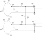
- FIG. 3 shows the first phase shift circuit 21 comprising a first capacitor 211 and a first inductor 212 , and the second phase shift circuit 22 comprising a second capacitor 221 and a second inductor 222 .
- 300 and 400 represent coaxial cables, respectively.
- tuning is first required in the production of coils, that is, the frequency of each coil unit is adjusted to the MR frequency.
- a coil unit is tuned, it is necessary to first disconnect the loops of all other coil units, and then adjust the capacitances of the capacitors on the loop of the coil unit until the frequency of the coil unit reaches the MR frequency.
- FIG. 3 there are only two coil units.
- the first coil unit 100 When the first coil unit 100 is tuned, it is necessary to disconnect the loop of the second coil unit 200 , for example, disconnect one of the capacitors C 21 , C 22 and C 23 on the loop of the second coil unit 200 , and then adjust the capacitances of the capacitors C 11 , C 12 and C 13 on the loop of the first coil unit 100 until the frequency of the first coil unit 100 reaches the MR frequency.
- the values of the first capacitor 211 , the first inductor 212 , the second capacitor 221 , the second inductor 222 and the first crossover element 120 are determined in the following way:
- the values of the first capacitor 211 , the first inductor 212 , the second capacitor 221 , the second inductor 222 and the first crossover element 120 are continuously adjusted, and the phase shift of the first connecting end of the first crossover element 120 between the current state and a non-matched state and the phase shift of the second connecting end of the first crossover element 120 between the current state and a non-matched state are respectively measured for each group of values through simulations.
- the two phase shifts are both 180°, the adjustment of the values of the above-mentioned elements is stopped, and it is determined that the first coil unit 100 and the second coil unit 200 are both in a matched state.
- the value of the first crossover element 120 is adjusted (the values of the first capacitor 211 , the first inductor 212 , the second capacitor 221 , and the second inductor 222 may need to be fine-tuned during this process) until optimal decoupling between the first coil unit 100 and the second coil unit 200 is achieved.
- the values of the first capacitor 211 , the first inductor 212 , the second capacitor 221 , the second inductor 222 and the first crossover element 120 are the desired values.
- the standard impedance of an RF circuit is usually 50 ohms.
- the impedances of the first connecting end and second connecting end of the first crossover element 120 reach 50 ohms during adjustments of the values of the first capacitor 211 , the first inductor 212 , the second capacitor 221 , the second inductor 222 and the first crossover element 120 , it indicates that the first coil unit 100 and the second coil unit 200 are in a matched state.
- the first phase shift circuit 21 further comprises a third capacitor 213
- the second phase shift circuit 22 further comprises a fourth capacitor 223 , wherein
- the values of the third capacitor 213 and/or the fourth capacitor 223 can further be adjusted to optimize the decoupling between the first coil unit 100 and the second coil unit 200 .
- FIG. 5 compares the port matching effects obtained after field simulations are performed for a coil unit in an MR system by use of simulation software, where the coil unit decoupling device provided by the present disclosure is applied and is not applied, respectively.
- m 3 represents the reflection parameter of signals on a simulation port (namely, a port connecting a crossover element and a phase shift circuit) on the coil unit, and the reflection parameter is denoted as S(1,1).
- the left graph shows the simulation when the coil unit decoupling device provided by the present disclosure is not applied, namely, the coil unit is in a non-matched state
- the right graph shows the simulation when the coil unit decoupling device provided by the present disclosure is applied and the coil unit is in a matched state.
- the first coil unit and the second coil unit may be symmetric with respect to a plane.
- decoupling between all coil units can be realized simply by applying the coil unit decoupling device provided by the present disclosure to every two coil units. It can be seen that the complexity is greatly lowered.
- the distance between the phase shift circuit connected with each coil unit and the crossover element may be long, and a cable is usually connected between the phase shift circuit and the crossover element in an MR system.
- the grounding of the cable may have an antenna effect.
- an RF trap may be connected between the phase shift circuit and the crossover element.
- a coil unit may not be grounded before a front-end amplifier, and in this case, an RF trap also needs to be added before the front-end amplifier.
- FIG. 6 shows that an RF trap 214 is added between the first inductor 212 and a front-end amplifier in the coil unit decoupling device 20 and an RF trap 224 is added between the second inductor 222 and a front-end amplifier.
- an RF trap can also be connected to the cable connecting the first crossover element 120 .
- an RF trap 215 is connected between the first crossover element 120 and the first inductor 212
- an RF trap 225 is connected between the first crossover element 120 and the second inductor 222
- the first inductor 212 and the second inductor 222 may be connected with the crossover element 120 by use of short cables or coaxial cables
- 401 and 402 shown in FIG. 7 are coaxial cables.
- FIG. 8 shows the circuit of the application of the coil unit decoupling device provided by the present disclosure to the coil units shown in FIG. 1 .
- the coil units 11 and 13 are symmetric with respect to a central vertical cross-section of the cylinder
- the coil unit 12 and 14 are symmetric with respect to a central vertical cross-section of the cylinder.
- the self-contained loop of each coil unit has four ports for connecting capacitors, one port is used for connecting the coil unit decoupling device provided by the present disclosure, and the other three ports are used for connecting capacitors.
- the ports 3 , 7 , 11 and 15 are used for connecting the decoupling device 20 provided by the present disclosure, and the other three ports on the self-contained loop of each coil unit are used for connecting capacitors.
- a crossover element is respectively connected between the phase shift circuits (namely, between coil units 11 and 12 , between coil units 11 and 13 , between coil units 11 and 14 , between coil units 12 and 13 , between coil units 12 and 14 and between coil units 13 and 14 ) of every two coil units, and the crossover elements shown in FIG. 8 are inductors or capacitors.
- the capacitances of the capacitors on the loops of the coil units 11 - 14 are adjusted until the frequency of the coil units is the MR frequency (80 MHz in the example).
- the port, connected with a crossover element, on each coil unit is a simulation port, and therefore there are four simulation ports, namely, there are ports 801 , 802 , 803 and 804 as shown in FIG. 8 .
- FIG. 9 shows the port matching effect and the decoupling effect obtained after field simulations are performed for the circuit shown in FIG. 8 by use of simulation software.
- dB(S(A,B)) represents the coupling described in terms of dB between the simulation port A and the simulation port B, and A and B may be any of ports 801 - 804 .
- dB(S(2,1)) represents the coupling described in terms of dB between the ports 802 and 801 .
- dB(S(2,1)) ⁇ 27.357
- dB(S(3,1)) ⁇ 11.191
- dB(S(3,2)) ⁇ 27.365
- dB(S(4,1)) ⁇ 27.458
- dB(S(4,2)) ⁇ 11.195
- dB(S(4,3)) ⁇ 27.368.
- S(A,A) represents the reflection coefficient of signals on the simulation port A, described in terms of phases and amplitudes, and A may be any of ports 801 - 804 .
- S(1,1) represents the reflection coefficient of signals on the port 801 , described in terms of phases and amplitudes.
- S(1,1) 0.016/13.563
- S(2,2) 0.025/ ⁇ 53.298
- S(3,3) 0.016/ ⁇ 2.472
- S(4,4) 0.016/10.280.
- the value before “/” represents an amplitude and the value after “/” represents a phase.
- FIG. 10 compares the reflection coefficients of signals on different simulation ports of the circuit shown in FIG. 8 before and after mistuning of the coil unit 11 .
- the upper left graph and the lower left graph show the results before mistuning of the coil unit 11
- the upper right graph and the lower right graph show the results after mistuning of the coil unit 11 .
- the coil unit decoupling device 20 can still be used to decouple other coil units in the MR system.
- the decoupling effect is not ideal, yet.
- the decoupling effect can be further improved by adding crossover elements (capacitors or inductors). As shown in FIG. 11 , a second crossover element 121 is connected between the first connecting end of the first inductor 212 and the first connecting end of the second inductor 222 .
- a crossover element (capacitor or inductor) is added between first connecting ends of the inductors in the phase shift circuit of every two coil units, and then the circuit shown in FIG. 12 is obtained.
- FIG. 13 shows the port matching effect and the decoupling effect obtained after field simulations are performed for the circuit in shown FIG. 12 by use of simulation software.
- dB(S(3,1)) and dB(S(4,2)) are further optimized to below ⁇ 30 dB, and that dB(S(3,2)), dB(S(4,1)), dB(S(4,3)) and dB(S(2,1)) are further optimized to below ⁇ 40 dB provided that each port still remains matched.
- the first inductor 212 may be replaced by a first inductor group consisting of a plurality of inductors connected in series, and/or the second inductor 222 may also be replaced by a second inductor group consisting of a plurality of inductors connected in series; in addition, according to the goal of achieving the optimal decoupling effect, for the first crossover element 120 , a connecting end may be selected from the connecting ends of the plurality of inductors in the first inductor group to connect the first connecting end of the first crossover element 120 , and a connecting end may be selected from the connecting ends of the plurality of inductors in the second inductor group to connect the second connecting end of the first crossover element 120 .
- FIG. 14 shows the structure of a coil unit decoupling device wherein the first inductor 212 is replaced by two inductors: inductor 2121 and inductor 2122 , and the second inductor 222 is replaced by two inductors: inductor 2221 and inductor 2222 , and in FIG. 14 , the first connecting end of the first crossover element 120 is connected with a second connecting end of the inductor 2121 and the second connecting end of the first crossover element 120 is connected with a second connecting end of the inductor 2221 .
- FIG. 16 shows the port matching effect and the decoupling effect obtained after field simulations are performed for the circuit shown in FIG. 15 by use of simulation software.
- each port has high matching and decoupling performances.
- FIG. 17 shows another alternative solution.
- the first inductor 212 on the first phase shift circuit 21 is replaced by two inductors: the inductor 2123 and the inductor 2124 , and only one inductor 2223 is still adopted on the second phase shift circuit 22 .
- the first connecting end of the first crossover element 120 is connected with the second connecting end of the inductor 2121 and the second connecting end of the first crossover element 120 is connected with the second connecting end of the inductor 2223 .
- FIG. 18 shows a still another alternative solution.
- the first inductor 212 on the first phase shift circuit 21 is replaced by two inductors: the inductor 2123 and the inductor 2124 , and only one inductor 2223 is still adopted on the second phase shift circuit 22 .
- the first connecting end of the first crossover element 120 is connected with the second connecting end of the inductor 2121
- the second connecting end of the first crossover element 120 is connected with the first connecting end of the inductor 2223 .
- first inductor 212 when the first inductor 212 is replaced by a first inductor group consisting of a plurality of inductors connected in series and the second inductor 222 is replaced by a second inductor group consisting of a plurality of inductors connected in series, a plurality of (for example, more than two) crossover elements can be adopted to achieve an optimal decoupling effect.
- the first connecting end of each crossover element can be connected with any connecting end of any inductor in the first inductor group
- the second connecting end of each crossover element can be connected with any connecting end of any inductor in the second inductor group.
- the coil unit decoupling device provided by the present disclosure must be placed before the front-end low-noise amplifier of a coil unit.
- the phase can be adjusted according to the actual requirements so that the coil unit and the front-end low-noise amplifier behind the coil unit can be decoupled and the coil unit and the amplifier can still work normally. For example, if the noise matching angle of the front-end low-noise amplifier is 45°, the phase of the port (namely, the port connected with the crossover element on the phase shift circuit of the coil unit, or the simulation port shown in FIG. 8 ) into which the coil unit is looked can be adjusted to ⁇ 135° by use of the phase shift circuit.
- FIG. 19 shows the port matching effect and the decoupling effect obtained after field simulations are performed in the case that the phase of the simulation ports on the circuit shown in FIG. 8 is ⁇ 135°.
- Table 1 lists the SNR losses when the coil unit decoupling device provided by aspects of the present disclosure is applied to the coil units shown in FIG. 1 and one, two or more than three crossover inductors with a Q-factor of 80 are adopted for capacitance coupling, inductance coupling and impedance coupling. It can be seen that the SNR losses are respectively 0.072 dB (1.6%) and 0.081 dB (1.8%) when one crossover inductor is adopted for decoupling, and the SNR losses respectively increase to 0.122 dB (2.85%) and 0.087 dB (2.02%) when two or more crossover inductors are adopted.
- aspects of the present disclosure further provide an MR system and the system comprises the above-mentioned coil unit decoupling device 20 .
Landscapes
- Physics & Mathematics (AREA)
- Condensed Matter Physics & Semiconductors (AREA)
- General Physics & Mathematics (AREA)
- High Energy & Nuclear Physics (AREA)
- Filters And Equalizers (AREA)
Abstract
Description
-
- a first connecting end of the first phase shift circuit is connected with a first port of a first coil unit;
- a second connecting end of the first phase shift circuit is connected with a first connecting end of the first crossover element;
- a first connecting end of the second phase shift circuit is connected with a first port of a second coil unit;
- a second connecting end of the second phase shift circuit is connected with a second connecting end of the first crossover element;
- the first phase shift circuit enables the first coil unit to be matched and enables the first coil unit to have a phase shift of 180° between a matched state and a non-matched state, the second phase shift circuit enables the second coil unit to be matched and enables the second coil unit to have a phase shift of 180° between a matched state and a non-matched state, the first coil unit and the second coil unit are located in a magnetic resonance system, the first port is any port on a self-contained loop of the first coil unit, and the second port is any port on a self-contained loop of the second coil unit.
-
- a first connecting end of the first capacitor is connected with the first port of the first coil unit and a first connecting end of the first inductor group, and a second connecting end of the first capacitor is grounded, wherein the first connecting end of the first inductor group is the connecting end of a first inductor in the first inductor group for an external connection, and a second connecting end of the first inductor group is the connecting end of a last inductor in the first inductor group for an external connection;
- and/or, the second phase shift circuit comprises a second capacitor and a second inductor group, wherein
- a first connecting end of the second capacitor is connected with the first port of the second coil unit and a first connecting end of the second inductor group, and a second connecting end of the second capacitor is grounded, wherein the first connecting end of the second inductor group is the connecting end of a first inductor in the second inductor group for an external connection, and a second connecting end of the second inductor group is the connecting end of a last inductor in the second inductor group for an external connection;
- the first connecting end of the first crossover element is connected with any connecting end of any inductor in the first inductor group, and the second connecting end of the first crossover element is connected with any connecting end of any inductor in the second inductor group.
-
- a first connecting end of the second crossover element is connected with the first connecting end of the first inductor group, and a second connecting end of the second crossover element is connected with the first connecting end of the second inductor group.
-
- a first connecting end of the third capacitor is connected with the second connecting end of the first inductor group, and a second connecting end of the third capacitor is grounded;
- a first connecting end of the fourth capacitor is connected with the second connecting end of the second inductor group, and a second connecting end of the fourth capacitor is grounded.
-
- the first RF traps are connected between the second connecting end of the first inductor group and the first connecting end of the first crossover element;
- the second RF traps are connected between the second connecting end of the second inductor group and the second connecting end of the first crossover element.
-
- a first connecting end of the first capacitor is connected with the first port of the first coil unit and a first connecting end of the first inductor, a second connecting end of the first capacitor is grounded, and a second connecting end of the first inductor is connected with the first connecting end of the first crossover element;
- the second phase shift circuit comprises a second capacitor and a second inductor, wherein
- a first connecting end of the second capacitor is connected with the first port of the second coil unit and a first connecting end of the second inductor, a second connecting end of the second capacitor is grounded, and a second connecting end of the second inductor is connected with the second connecting end of the first crossover element.
-
- a first connecting end of the first capacitor is connected with the first port of the first coil unit and a first connecting end of the third inductor, a second connecting end of the first capacitor is grounded, and a second connecting end of the third inductor is connected with the first connecting end of the first crossover element and a first connecting end of the fourth inductor;
- the second phase shift circuit comprises a second capacitor, a fifth inductor and a sixth inductor, wherein
- a first connecting end of the second capacitor is connected with the first port of the second coil unit and a first connecting end of the fifth inductor, a second connecting end of the second capacitor is grounded, and a second connecting end of the fifth inductor is connected with the second connecting end of the first crossover element and a first connecting end of the sixth inductor.
-
- a first connecting end of the first capacitor is connected with the first port of the first coil unit and a first connecting end of the seventh inductor, a second connecting end of the first capacitor is grounded, and a second connecting end of the seventh inductor is connected with the first connecting end of the first crossover element and a first connecting end of the eighth inductor;
- the second phase shift circuit comprises a second capacitor and a ninth inductor, wherein
- a first connecting end of the second capacitor is connected with the first port of the second coil unit and a first connecting end of the ninth inductor, a second connecting end of the second capacitor is grounded, and a second connecting end of the ninth inductor is connected with the second connecting end of the first crossover element.
-
- a first connecting end of the first capacitor is connected with the first port of the first coil unit and a first connecting end of the seventh inductor, a second connecting end of the first capacitor is grounded, and a second connecting end of the seventh inductor is connected with the first connecting end of the first crossover element and a first connecting end of the eighth inductor;
- the second phase shift circuit comprises a second capacitor and a ninth inductor, wherein
- a first connecting end of the second capacitor is connected with the first port of the second coil unit, a first connecting end of the ninth inductor and a second connecting end of the first crossover element, and a second connecting end of the second capacitor is grounded.
| Reference numeral | Meaning | ||
| 11-14 | |
||
| 20 | Coil unit decoupling device provided | ||
| by the |
|||
| 100 | |
||
| 200 | |
||
| 21 | First |
||
| 22 | Second |
||
| 120 | |
||
| 121 | |
||
| 101 | First port of |
||
| 201 | First port of |
||
| 211 | |
||
| 212 | |
||
| 2121 | |
||
| 2122 | |
||
| 2123 | |
||
| 2124 | |
||
| 213 | |
||
| 214, 215 | |
||
| 221 | |
||
| 222 | |
||
| 2221 | |
||
| 2222 | |
||
| 2223 | |
||
| 223 | |
||
| 224, 225 | Second RF trap | ||
-
- a first connecting end of the first
phase shift circuit 21 is connected with afirst port 101 of a first coil unit; - a second connecting end of the first
phase shift circuit 21 is connected with a first connecting end of thefirst crossover element 120; - a first connecting end of the second
phase shift circuit 22 is connected with afirst port 201 of a second coil unit; - a second connecting end of the second
phase shift circuit 22 is connected with a second connecting end of thefirst crossover element 120; - wherein, the first
phase shift circuit 21 enables the first coil unit to be matched and enables the first coil unit to have a phase shift of 180° between a matched state and a non-matched state; the secondphase shift circuit 22 enables the second coil unit to be matched and enables the second coil unit to have a phase shift of 180° between a matched state and a non-matched state, the first coil unit and the second coil unit are located in an MR system, thefirst port 101 is any port on the self-contained loop of the first coil unit, and thesecond port 201 is any port on the self-contained loop of the second coil unit.
- a first connecting end of the first
-
- a first connecting end of the
first capacitor 211 is connected with afirst port 101 of afirst coil unit 100 and a first connecting end of thefirst inductor 212, a second connecting end of thefirst capacitor 211 is grounded, a second connecting end of thefirst inductor 212 is connected with a first connecting end of afirst crossover element 120, and the second connecting end of thefirst inductor 212 is also connected with a subsequent circuit of thefirst coil unit 100, for example, the input end of a front-end low-noise amplifier of thefirst coil unit 100, through a signal line; - and/or, the second
phase shift circuit 22 comprises asecond capacitor 221 and asecond inductor 222, wherein - a first connecting end of the
second capacitor 221 is connected with thefirst port 201 of thesecond coil unit 200 and a first connecting end of thesecond inductor 222, a second connecting end of thesecond capacitor 221 is grounded, and a second connecting end of thesecond inductor 222 is connected with the second connecting end of thefirst crossover element 120. The second connecting end of thesecond inductor 222 is also connected with a subsequent circuit of thesecond coil unit 200, for example, the input end of a front-end low-noise amplifier of thesecond coil unit 200, through a signal line.
- a first connecting end of the
-
- a first connecting end of the
third capacitor 213 is connected with the first connecting end of thefirst crossover element 120, and a second connecting end of thethird capacitor 213 is grounded; - a first connecting end of the
fourth capacitor 223 is connected with the second connecting end of thefirst crossover element 120, and a second connecting end of thefourth capacitor 223 is grounded.
- a first connecting end of the
| TABLE 1 | |||||
| SNR loss when | SNR loss when | SNR loss when | SNR loss when | ||
| one crossover | two crossover | more than three | one crossover | ||
| inductor is | inductors are | crossover inductors | element is | ||
| adopted for | adopted for | are adopted | adopted for | ||
| capacitance | capacitance, | for capacitance, | capacitance, | ||
| and inductance | inductance and | inductance and | inductance and | ||
| decoupling | impedance decoupling | impedance decoupling | impedance decoupling | ||
| Coil unit 1 | 0.071 | 0.122 | 0.087 | 0.081 |
| Coil unit 2 | 0.072 | 0.122 | 0.086 | 0.081 |
| |
0.071 | 0.122 | 0.087 | 0.081 |
| |
0.072 | 0.122 | 0.087 | 0.081 |
-
- 1. The coil unit decoupling device provided aspects of the present disclosure is structurally simple, is easy to implement and has a strong decoupling effect. Coil units can systematically be adjusted, without any difficulty.
- 2. No complex copper structure is required and the SRN at the center of coil structure can remain an optimal value.
- 3. The coil unit decoupling device provided aspects of the present disclosure is especially applicable to a low-field system where the Q-factor is high and it is difficult to realize decoupling.
- 4. The coil unit decoupling device provided aspects of the present disclosure can still achieve a good decoupling effect when one or more coil units are mistuned.
Claims (11)
Applications Claiming Priority (2)
| Application Number | Priority Date | Filing Date | Title |
|---|---|---|---|
| CN202110062772.8A CN114814683A (en) | 2021-01-18 | 2021-01-18 | Coupling unit decoupling device and magnetic resonance system |
| CN202110062772.8 | 2021-01-18 |
Publications (2)
| Publication Number | Publication Date |
|---|---|
| US20220229129A1 US20220229129A1 (en) | 2022-07-21 |
| US11874349B2 true US11874349B2 (en) | 2024-01-16 |
Family
ID=82405085
Family Applications (1)
| Application Number | Title | Priority Date | Filing Date |
|---|---|---|---|
| US17/576,107 Active US11874349B2 (en) | 2021-01-18 | 2022-01-14 | Cross inductor/capacitor to simplify MRI coil element decoupling |
Country Status (2)
| Country | Link |
|---|---|
| US (1) | US11874349B2 (en) |
| CN (1) | CN114814683A (en) |
Families Citing this family (1)
| Publication number | Priority date | Publication date | Assignee | Title |
|---|---|---|---|---|
| US11835606B2 (en) * | 2021-10-18 | 2023-12-05 | Quality Electrodynamics, Llc | Decoupled MRI coils through coil matching |
Citations (15)
| Publication number | Priority date | Publication date | Assignee | Title |
|---|---|---|---|---|
| US5208534A (en) * | 1989-08-09 | 1993-05-04 | Kabushiki Kaisha Toshiba | Magnetic resonance imaging system |
| US5430378A (en) * | 1994-02-22 | 1995-07-04 | Board Of Regents - Univ Of Ne | NMR quadrature detection array |
| US5450011A (en) * | 1992-05-07 | 1995-09-12 | U.S. Philips Corporation | Magnetic resonance apparatus having a wideband matching network |
| US5543713A (en) * | 1994-12-01 | 1996-08-06 | The Regents Of The University Of California | Ground breaker for multiple control lines |
| US5708361A (en) | 1995-09-29 | 1998-01-13 | Siemens Aktiengesellschaft | Antenna arrangement for a magnetic resonance apparatus |
| US6351124B1 (en) * | 1999-06-23 | 2002-02-26 | Siemens Aktiengesellschaft | Antenna system for the reception of magnetic resonance signals |
| US20060006870A1 (en) | 2004-07-02 | 2006-01-12 | Wang Jian M | Receiver coil array for a magnetic resonance imaging system |
| CN1941500A (en) | 2005-09-30 | 2007-04-04 | 西门子(中国)有限公司 | Decoupling method of RF transmitting coils |
| US20090128154A1 (en) * | 2007-11-15 | 2009-05-21 | General Electric Company | Ultra low output impedance rf power amplifier for parallel excitation |
| US20130271143A1 (en) * | 2012-04-12 | 2013-10-17 | Markus Vester | Reduction of Coupling Effects Between Coil Elements of a Magnetic Resonance Coil Arrangement |
| US20130314091A1 (en) * | 2011-02-14 | 2013-11-28 | Hitachi, Ltd. | Rf coil and magnetic resonance imaging device |
| US20160223629A1 (en) * | 2015-02-04 | 2016-08-04 | Stephan Biber | Magnetic resonance device |
| US20190257897A1 (en) | 2018-02-19 | 2019-08-22 | Quality Electrodynamics, Llc | Multi-turn magnetic resonance imaging (mri) array coil with ring decoupling for improved coil isolation |
| US20190339344A1 (en) * | 2017-01-13 | 2019-11-07 | Siemens Healthcare Gmbh | Magnetic resonance scanner and local coil matrix for operation at low magnetic field strengths |
| US20200096584A1 (en) * | 2018-09-24 | 2020-03-26 | Quality Electrodynamics, Llc | Multi-tune magnetic resonance imaging (mri) coil using different matching impedances |
Family Cites Families (5)
| Publication number | Priority date | Publication date | Assignee | Title |
|---|---|---|---|---|
| JP2552980Y2 (en) * | 1992-05-06 | 1997-11-05 | ジーイー横河メディカルシステム株式会社 | MR endoscope |
| CN101256222B (en) * | 2007-02-28 | 2010-09-29 | 西门子(中国)有限公司 | A magnetic resonance imaging system receiving coil circuit and its detuning method |
| US8390287B2 (en) * | 2007-03-26 | 2013-03-05 | The University Of Queensland | Coil decoupling |
| CN101520496B (en) * | 2008-02-29 | 2011-12-07 | 西门子(中国)有限公司 | Figure type coil for magnetic resonance imaging system |
| CN207752132U (en) * | 2017-12-29 | 2018-08-21 | 上海联影医疗科技有限公司 | Scanning coil component, scanning coil group and magnetic resonance system |
-
2021
- 2021-01-18 CN CN202110062772.8A patent/CN114814683A/en active Pending
-
2022
- 2022-01-14 US US17/576,107 patent/US11874349B2/en active Active
Patent Citations (16)
| Publication number | Priority date | Publication date | Assignee | Title |
|---|---|---|---|---|
| US5208534A (en) * | 1989-08-09 | 1993-05-04 | Kabushiki Kaisha Toshiba | Magnetic resonance imaging system |
| US5450011A (en) * | 1992-05-07 | 1995-09-12 | U.S. Philips Corporation | Magnetic resonance apparatus having a wideband matching network |
| US5430378A (en) * | 1994-02-22 | 1995-07-04 | Board Of Regents - Univ Of Ne | NMR quadrature detection array |
| US5543713A (en) * | 1994-12-01 | 1996-08-06 | The Regents Of The University Of California | Ground breaker for multiple control lines |
| US5708361A (en) | 1995-09-29 | 1998-01-13 | Siemens Aktiengesellschaft | Antenna arrangement for a magnetic resonance apparatus |
| US6351124B1 (en) * | 1999-06-23 | 2002-02-26 | Siemens Aktiengesellschaft | Antenna system for the reception of magnetic resonance signals |
| US20060006870A1 (en) | 2004-07-02 | 2006-01-12 | Wang Jian M | Receiver coil array for a magnetic resonance imaging system |
| US20070085540A1 (en) * | 2005-09-30 | 2007-04-19 | Du Jian J | Method for developing a transmit coil of a magnetic resonance system |
| CN1941500A (en) | 2005-09-30 | 2007-04-04 | 西门子(中国)有限公司 | Decoupling method of RF transmitting coils |
| US20090128154A1 (en) * | 2007-11-15 | 2009-05-21 | General Electric Company | Ultra low output impedance rf power amplifier for parallel excitation |
| US20130314091A1 (en) * | 2011-02-14 | 2013-11-28 | Hitachi, Ltd. | Rf coil and magnetic resonance imaging device |
| US20130271143A1 (en) * | 2012-04-12 | 2013-10-17 | Markus Vester | Reduction of Coupling Effects Between Coil Elements of a Magnetic Resonance Coil Arrangement |
| US20160223629A1 (en) * | 2015-02-04 | 2016-08-04 | Stephan Biber | Magnetic resonance device |
| US20190339344A1 (en) * | 2017-01-13 | 2019-11-07 | Siemens Healthcare Gmbh | Magnetic resonance scanner and local coil matrix for operation at low magnetic field strengths |
| US20190257897A1 (en) | 2018-02-19 | 2019-08-22 | Quality Electrodynamics, Llc | Multi-turn magnetic resonance imaging (mri) array coil with ring decoupling for improved coil isolation |
| US20200096584A1 (en) * | 2018-09-24 | 2020-03-26 | Quality Electrodynamics, Llc | Multi-tune magnetic resonance imaging (mri) coil using different matching impedances |
Non-Patent Citations (1)
| Title |
|---|
| P. B. Roemer et al: "The NMR Phased Array", Magnetic Resonance in Medicine 16, pp. 192-225, 1990. |
Also Published As
| Publication number | Publication date |
|---|---|
| CN114814683A (en) | 2022-07-29 |
| US20220229129A1 (en) | 2022-07-21 |
Similar Documents
| Publication | Publication Date | Title |
|---|---|---|
| US4827219A (en) | Remotely adjustable MRI RF coil impedance matching circuit with mutualy coupled resonators | |
| US7616000B2 (en) | Ultra low output impedance RF power amplifier for parallel excitation | |
| US5424645A (en) | Doubly broadband triple resonance or quad resonance NMR probe circuit | |
| AU2007341704B2 (en) | High frequency filter with closed circuit coupling | |
| US9761367B2 (en) | Multiplexers using weakly-coupled networks in RF front end circuitry | |
| US20050219010A1 (en) | Signal separating device | |
| US5179332A (en) | NMR radio frequency coil with disable circuit | |
| EP0823058A1 (en) | Method and apparatus for eliminating mutual inductance effects in resonant coil assemblies | |
| US7123090B2 (en) | Low-noise preamplifier, in particular, for nuclear magnetic resonance (NMR) | |
| US11874349B2 (en) | Cross inductor/capacitor to simplify MRI coil element decoupling | |
| CN111965577A (en) | Multi-frequency coil | |
| US20190260345A1 (en) | Rf filtering circuitry | |
| CN113655422A (en) | Magnetic resonance radio frequency transmitting device and magnetic resonance system | |
| JP2003510939A (en) | Narrowband tuned resonator filter topology with high selectivity, low insertion loss and improved out-of-band rejection in the extended frequency range | |
| EP1710596B1 (en) | NMR probe circuit with nodal impedance bridge | |
| US7239144B2 (en) | Antenna amplifier, in particular for a magnetic resonance antenna | |
| JP2023076843A (en) | variable bandpass filter | |
| US11699982B2 (en) | Coil unit decoupling apparatus and magnetic resonance system | |
| US20210242589A1 (en) | Coil and device for wireless signal transmission, and method for producing such a coil | |
| CN111965576B (en) | Single-port double-frequency coil | |
| US20110148542A1 (en) | Transformer and method for using same | |
| US8648674B2 (en) | Filter circuit, and wireless communication module and wireless communication device that uses the same | |
| JP6886424B2 (en) | Variable bandpass filter | |
| US2159546A (en) | Antenna coupling device for radio receivers | |
| JP3621468B2 (en) | Multi-frequency tuned loop antenna device |
Legal Events
| Date | Code | Title | Description |
|---|---|---|---|
| FEPP | Fee payment procedure |
Free format text: ENTITY STATUS SET TO UNDISCOUNTED (ORIGINAL EVENT CODE: BIG.); ENTITY STATUS OF PATENT OWNER: LARGE ENTITY |
|
| STPP | Information on status: patent application and granting procedure in general |
Free format text: DOCKETED NEW CASE - READY FOR EXAMINATION |
|
| AS | Assignment |
Owner name: SIEMENS SHENZHEN MAGNETIC RESONANCE LTD., CHINA Free format text: ASSIGNMENT OF ASSIGNORS INTEREST;ASSIGNORS:WANG, JIANMIN;ZHANG, QIU YI;REEL/FRAME:059573/0761 Effective date: 20220223 Owner name: SIEMENS HEALTHCARE GMBH, GERMANY Free format text: ASSIGNMENT OF ASSIGNORS INTEREST;ASSIGNOR:SIEMENS SHENZHEN MAGNETIC RESONANCE LTD.;REEL/FRAME:059683/0154 Effective date: 20220303 |
|
| STPP | Information on status: patent application and granting procedure in general |
Free format text: NON FINAL ACTION MAILED |
|
| STPP | Information on status: patent application and granting procedure in general |
Free format text: RESPONSE TO NON-FINAL OFFICE ACTION ENTERED AND FORWARDED TO EXAMINER |
|
| STPP | Information on status: patent application and granting procedure in general |
Free format text: NOTICE OF ALLOWANCE MAILED -- APPLICATION RECEIVED IN OFFICE OF PUBLICATIONS |
|
| STPP | Information on status: patent application and granting procedure in general |
Free format text: PUBLICATIONS -- ISSUE FEE PAYMENT RECEIVED |
|
| STPP | Information on status: patent application and granting procedure in general |
Free format text: PUBLICATIONS -- ISSUE FEE PAYMENT VERIFIED |
|
| AS | Assignment |
Owner name: SIEMENS HEALTHINEERS AG, GERMANY Free format text: ASSIGNMENT OF ASSIGNORS INTEREST;ASSIGNOR:SIEMENS HEALTHCARE GMBH;REEL/FRAME:066267/0346 Effective date: 20231219 Owner name: SIEMENS HEALTHINEERS AG, GERMANY Free format text: ASSIGNMENT OF ASSIGNOR'S INTEREST;ASSIGNOR:SIEMENS HEALTHCARE GMBH;REEL/FRAME:066267/0346 Effective date: 20231219 |
|
| STCF | Information on status: patent grant |
Free format text: PATENTED CASE |