US11873311B2 - Heterocyclic compound, organic electroluminescent device, and electronic device - Google Patents

Heterocyclic compound, organic electroluminescent device, and electronic device Download PDF

Info

Publication number
US11873311B2
US11873311B2 US17/788,850 US202017788850A US11873311B2 US 11873311 B2 US11873311 B2 US 11873311B2 US 202017788850 A US202017788850 A US 202017788850A US 11873311 B2 US11873311 B2 US 11873311B2
Authority
US
United States
Prior art keywords
carbon atoms
heterocyclic compound
compound
organic electroluminescent
independently selected
Prior art date
Legal status (The legal status is an assumption and is not a legal conclusion. Google has not performed a legal analysis and makes no representation as to the accuracy of the status listed.)
Active, expires
Application number
US17/788,850
Other versions
US20230312604A1 (en
Inventor
Jinping Wang
Zhen Xue
Zhiwei Chen
Current Assignee (The listed assignees may be inaccurate. Google has not performed a legal analysis and makes no representation or warranty as to the accuracy of the list.)
Shaanxi Lighte Optoelectronics Material Co Ltd
Original Assignee
Shaanxi Lighte Optoelectronics Material Co Ltd
Priority date (The priority date is an assumption and is not a legal conclusion. Google has not performed a legal analysis and makes no representation as to the accuracy of the date listed.)
Filing date
Publication date
Priority claimed from CN202011519965.3A external-priority patent/CN113121572B/en
Application filed by Shaanxi Lighte Optoelectronics Material Co Ltd filed Critical Shaanxi Lighte Optoelectronics Material Co Ltd
Assigned to SHAANXI LIGHTE OPTOELECTRONICS MATERIAL CO., LTD. reassignment SHAANXI LIGHTE OPTOELECTRONICS MATERIAL CO., LTD. ASSIGNMENT OF ASSIGNORS INTEREST (SEE DOCUMENT FOR DETAILS). Assignors: CHEN, ZHIWEI, WANG, JINPING, XUE, Zhen
Publication of US20230312604A1 publication Critical patent/US20230312604A1/en
Application granted granted Critical
Publication of US11873311B2 publication Critical patent/US11873311B2/en
Active legal-status Critical Current
Adjusted expiration legal-status Critical

Links

Images

Classifications

    • CCHEMISTRY; METALLURGY
    • C07ORGANIC CHEMISTRY
    • C07DHETEROCYCLIC COMPOUNDS
    • C07D471/00Heterocyclic compounds containing nitrogen atoms as the only ring hetero atoms in the condensed system, at least one ring being a six-membered ring with one nitrogen atom, not provided for by groups C07D451/00 - C07D463/00
    • C07D471/02Heterocyclic compounds containing nitrogen atoms as the only ring hetero atoms in the condensed system, at least one ring being a six-membered ring with one nitrogen atom, not provided for by groups C07D451/00 - C07D463/00 in which the condensed system contains two hetero rings
    • C07D471/04Ortho-condensed systems
    • CCHEMISTRY; METALLURGY
    • C07ORGANIC CHEMISTRY
    • C07DHETEROCYCLIC COMPOUNDS
    • C07D405/00Heterocyclic compounds containing both one or more hetero rings having oxygen atoms as the only ring hetero atoms, and one or more rings having nitrogen as the only ring hetero atom
    • C07D405/14Heterocyclic compounds containing both one or more hetero rings having oxygen atoms as the only ring hetero atoms, and one or more rings having nitrogen as the only ring hetero atom containing three or more hetero rings
    • CCHEMISTRY; METALLURGY
    • C07ORGANIC CHEMISTRY
    • C07DHETEROCYCLIC COMPOUNDS
    • C07D409/00Heterocyclic compounds containing two or more hetero rings, at least one ring having sulfur atoms as the only ring hetero atoms
    • C07D409/14Heterocyclic compounds containing two or more hetero rings, at least one ring having sulfur atoms as the only ring hetero atoms containing three or more hetero rings
    • CCHEMISTRY; METALLURGY
    • C07ORGANIC CHEMISTRY
    • C07DHETEROCYCLIC COMPOUNDS
    • C07D519/00Heterocyclic compounds containing more than one system of two or more relevant hetero rings condensed among themselves or condensed with a common carbocyclic ring system not provided for in groups C07D453/00 or C07D455/00
    • CCHEMISTRY; METALLURGY
    • C09DYES; PAINTS; POLISHES; NATURAL RESINS; ADHESIVES; COMPOSITIONS NOT OTHERWISE PROVIDED FOR; APPLICATIONS OF MATERIALS NOT OTHERWISE PROVIDED FOR
    • C09KMATERIALS FOR MISCELLANEOUS APPLICATIONS, NOT PROVIDED FOR ELSEWHERE
    • C09K11/00Luminescent, e.g. electroluminescent, chemiluminescent materials
    • C09K11/06Luminescent, e.g. electroluminescent, chemiluminescent materials containing organic luminescent materials
    • HELECTRICITY
    • H10SEMICONDUCTOR DEVICES; ELECTRIC SOLID-STATE DEVICES NOT OTHERWISE PROVIDED FOR
    • H10KORGANIC ELECTRIC SOLID-STATE DEVICES
    • H10K50/00Organic light-emitting devices
    • H10K50/10OLEDs or polymer light-emitting diodes [PLED]
    • H10K50/11OLEDs or polymer light-emitting diodes [PLED] characterised by the electroluminescent [EL] layers
    • HELECTRICITY
    • H10SEMICONDUCTOR DEVICES; ELECTRIC SOLID-STATE DEVICES NOT OTHERWISE PROVIDED FOR
    • H10KORGANIC ELECTRIC SOLID-STATE DEVICES
    • H10K85/00Organic materials used in the body or electrodes of devices covered by this subclass
    • HELECTRICITY
    • H10SEMICONDUCTOR DEVICES; ELECTRIC SOLID-STATE DEVICES NOT OTHERWISE PROVIDED FOR
    • H10KORGANIC ELECTRIC SOLID-STATE DEVICES
    • H10K85/00Organic materials used in the body or electrodes of devices covered by this subclass
    • H10K85/60Organic compounds having low molecular weight
    • H10K85/615Polycyclic condensed aromatic hydrocarbons, e.g. anthracene
    • H10K85/622Polycyclic condensed aromatic hydrocarbons, e.g. anthracene containing four rings, e.g. pyrene
    • HELECTRICITY
    • H10SEMICONDUCTOR DEVICES; ELECTRIC SOLID-STATE DEVICES NOT OTHERWISE PROVIDED FOR
    • H10KORGANIC ELECTRIC SOLID-STATE DEVICES
    • H10K85/00Organic materials used in the body or electrodes of devices covered by this subclass
    • H10K85/60Organic compounds having low molecular weight
    • H10K85/649Aromatic compounds comprising a hetero atom
    • H10K85/652Cyanine dyes
    • HELECTRICITY
    • H10SEMICONDUCTOR DEVICES; ELECTRIC SOLID-STATE DEVICES NOT OTHERWISE PROVIDED FOR
    • H10KORGANIC ELECTRIC SOLID-STATE DEVICES
    • H10K85/00Organic materials used in the body or electrodes of devices covered by this subclass
    • H10K85/60Organic compounds having low molecular weight
    • H10K85/649Aromatic compounds comprising a hetero atom
    • H10K85/654Aromatic compounds comprising a hetero atom comprising only nitrogen as heteroatom
    • HELECTRICITY
    • H10SEMICONDUCTOR DEVICES; ELECTRIC SOLID-STATE DEVICES NOT OTHERWISE PROVIDED FOR
    • H10KORGANIC ELECTRIC SOLID-STATE DEVICES
    • H10K85/00Organic materials used in the body or electrodes of devices covered by this subclass
    • H10K85/60Organic compounds having low molecular weight
    • H10K85/649Aromatic compounds comprising a hetero atom
    • H10K85/657Polycyclic condensed heteroaromatic hydrocarbons
    • H10K85/6572Polycyclic condensed heteroaromatic hydrocarbons comprising only nitrogen in the heteroaromatic polycondensed ring system, e.g. phenanthroline or carbazole
    • HELECTRICITY
    • H10SEMICONDUCTOR DEVICES; ELECTRIC SOLID-STATE DEVICES NOT OTHERWISE PROVIDED FOR
    • H10KORGANIC ELECTRIC SOLID-STATE DEVICES
    • H10K85/00Organic materials used in the body or electrodes of devices covered by this subclass
    • H10K85/60Organic compounds having low molecular weight
    • H10K85/649Aromatic compounds comprising a hetero atom
    • H10K85/657Polycyclic condensed heteroaromatic hydrocarbons
    • H10K85/6574Polycyclic condensed heteroaromatic hydrocarbons comprising only oxygen in the heteroaromatic polycondensed ring system, e.g. cumarine dyes
    • HELECTRICITY
    • H10SEMICONDUCTOR DEVICES; ELECTRIC SOLID-STATE DEVICES NOT OTHERWISE PROVIDED FOR
    • H10KORGANIC ELECTRIC SOLID-STATE DEVICES
    • H10K85/00Organic materials used in the body or electrodes of devices covered by this subclass
    • H10K85/60Organic compounds having low molecular weight
    • H10K85/649Aromatic compounds comprising a hetero atom
    • H10K85/657Polycyclic condensed heteroaromatic hydrocarbons
    • H10K85/6576Polycyclic condensed heteroaromatic hydrocarbons comprising only sulfur in the heteroaromatic polycondensed ring system, e.g. benzothiophene
    • CCHEMISTRY; METALLURGY
    • C07ORGANIC CHEMISTRY
    • C07BGENERAL METHODS OF ORGANIC CHEMISTRY; APPARATUS THEREFOR
    • C07B2200/00Indexing scheme relating to specific properties of organic compounds
    • C07B2200/05Isotopically modified compounds, e.g. labelled

Definitions

  • the application relates to the technical field of organic electroluminescence, in particular to a heterocyclic compound, an organic electroluminescence device and an electronic device.
  • Organic electroluminescent devices such as organic light-emitting diodes (OLEDs) generally include a cathode and an anode which are disposed oppositely, and a functional layer disposed between the cathode and the anode.
  • the functional layer is composed of multiple organic or inorganic film layers and generally includes an organic light-emitting layer, a hole transporting layer located between the organic light-emitting layer and the anode and an electron transporting layer located between the organic light-emitting layer and the cathode.
  • the information applied by the background part is only used for enhancing the understanding of the background of the discloser, so the information can include information which does not constitute the prior art known to those of ordinary skill in the art.
  • the discloser aims to provide a heterocyclic compound, an organic electroluminescent device and an electronic device so as to improve the performance of the organic electroluminescent device.
  • the discloser adopts the following technical solution.
  • a heterocyclic compound is provided, and the heterocyclic compound has a structure shown in Formula 1-1:
  • a heterocyclic compound is provided, and the heterocyclic compound has a structure shown in Formula 1:
  • an organic electroluminescent device including an anode and a cathode which are oppositely arranged, and a functional layer arranged between the anode and the cathode, and the functional layer includes the heterocyclic compounds.
  • an electronic device including the above organic electroluminescent device.
  • a molecular structure of the heterocyclic compound of Formula 1 provided by the discloser is integrally of a planar structure, so that electron migration is facilitated, the electron transport rate is increased, and the luminous efficiency is high, and meanwhile, the molecule contains a plurality of electron-donating atom nitrogen, and the structure can form large conjugation, so that the electron cloud density is large, and the efficiency is high.
  • the structure of the heterocyclic compound is shown as Formula 1-1, in this structure, pyrido[2,3-b]indole in the heterocyclic compound is bound to a triazine group which is also electron-deficient, so that the electron injection and transport capability of the material can be effectively improved, the balance degree of hole and electron injection is enhanced, and this heterocyclic compound is particularly suitable for being used as a host material of a light-emitting layer to improve the luminous efficiency and the service life of the device.
  • FIG. 1 is a structural schematic diagram of an organic electroluminescent device in one embodiment of the discloser.
  • FIG. 2 is a structural schematic diagram of an electronic device in one embodiment of the discloser.
  • anode 100 , anode; 200 , cathode; 310 , hole injecting layer; 321 , hole transporting layer; 322 , electron blocking layer; 330 , organic light-emitting layer; 340 , electron transporting layer; 350 , electron injecting layer; 400 , electronic device.
  • the disclosure provides a heterocyclic compound, having a structure as shown in Formula 1:
  • the number of carbon atoms in Ar refers to the number of all carbon atoms.
  • Ar is selected from a substituted aryl with 10 carbon atoms
  • the number of all carbon atoms of the aryl and substituents on the aryl is 10.
  • Ar is 9,9-dimethylfluorenyl
  • Ar is a substituted fluorenyl with 15 carbon atoms
  • the substituents in Ar are two methyl
  • the number of ring-forming carbon atoms in Ar is 13.
  • R 1 and R 2 may also be connected to form a ring together with the atom to which they are jointly connected” includes the following two cases: a case in which R 1 and R 2 are connected to form a ring together with the atom to which they are jointly connected; and a case in which R 1 and R 2 are each independently present and are not connected to each other and do not form a ring.
  • aryl refers to an optional functional group or substituent derived from an aromatic hydrocarbon ring.
  • the aryl may be a monocyclic aryl or a polycyclic aryl, in other words, the aryl can be a monocyclic aryl, a condensed ring aryl (i.e., fused aryl), two or more monocyclic aryl conjugatedly connected through carbon-carbon bonds, a monocyclic aryl and a fused aryl which are conjugatedly connected through a carbon-carbon bond, and two or more fused aryl conjugatedly connected through carbon-carbon bonds.
  • two or more aromatic groups conjugatedly connected by carbon-carbon bonds may also be regarded as the aryl of the present discloser.
  • the aryl does not contain heteroatoms such as B, N, O, S or P.
  • biphenyl, terphenyl, etc. are aryl groups.
  • the aryl groups may include phenyl, naphthyl, fluorenyl, anthryl, phenanthryl, biphenyl, terphenyl, quaterphenyl, quinquephenyl, benzo[9,10]phenanthryl, pyrenyl, benzofluoranthenyl, chrysene, and the like, but are not limited thereto.
  • naphthyl, fluorenyl, anthryl, phenanthryl and the like belong to the condensed ring aryl
  • phenyl, biphenyl, terphenyl and other monocyclic aryl connected through a carbon-carbon single bond do not belong to the condensed ring aryl.
  • the substituted aryl means that one or more hydrogen atoms in the aryl are substituted by other groups.
  • at least one hydrogen atom is substituted by a deuterium atom, F, Cl, I, CN, branched alkyl, linear alkyl, cycloalkyl, alkoxy, alkylthio or other groups.
  • the number of carbon atoms in the substituted aryl is the total number of carbon atoms in the aryl and substituents on the aryl.
  • substituted aryl having 18 carbon atoms means that the total number of carbon atoms in the aryl and the substituents on the aryl is 18.
  • 9,9-dimethylfluorenyl is fluorenyl which has 15 carbon atoms and is substituted by methyl.
  • heteroaryl may be a heteroaryl group including at least one of B, O, N, P, Se, Si, and S as a heteroatom.
  • the heteroaryl group may be a monocyclic heteroaryl or a polycyclic heteroaryl.
  • the heteroaryl group may be a single aromatic ring system or multiple aromatic ring systems conjugatedly connected through carbon-carbon bonds, and any aromatic ring system is an aromatic monocyclic ring or an aromatic fused ring.
  • the heteroaryl may include thienyl, furyl, pyrrolyl, imidazolyl, thiazolyl, oxazolyl, oxadiazolyl, triazolyl, pyridyl, bipyridyl, pyrimidinyl, triazinyl, acridinyl, pyridazinyl, pyrazinyl, quinolyl, quinazolinyl, quinoxalinyl, phenoxazinyl, phthalazinyl, pyridinopyrimidyl, pyridinopyrazinyl, pyrazinopyrazinyl, isoquinolyl, indolyl, carbazolyl, N-phenylcarbazolyl, N-pyridylcarbazolyl, N-methylcarbazolyl, benzoxazolyl, benzimidazolyl, benzothiazolyl, benzocarbazolyl, triazo
  • thienyl, furyl, phenanthrolinyl and the like are heteroaryl groups of the single aromatic ring system
  • N-phenylcarbazolyl, N-pyridylcarbazolyl, phenyl-substituted dibenzofuranyl, dibenzofuranyl-substituted phenyl and the like are heteroaryl groups of the multiple aromatic ring systems conjugatedly connected through carbon-carbon bonds.
  • the adopted description modes “each . . . independently”, “ . . . respectively and independently“and” . . . independently selected from” can be interchanged, and should be understood in a broad sense, which means that in different groups, specific options expressed between the same symbols do not influence each other, or in a same group, specific options expressed between the same symbols do not influence each other.
  • each q is independently 0, 1, 2 or 3, and each R′′ is independently selected from hydrogen, fluorine, or chlorine”, means that: Formula Q-1 represents that q substituents R′′ exist on a benzene ring, each R′′ may be the same or different, and options of each R′′ do not influence each other; Formula Q-2 represents that each benzene ring of biphenyl has q substituents R′′, the number q of the substituents R′′ on the two benzene rings may be the same or different, each R′′ may be the same or different, and options of each R′′ do not influence each other.
  • a non-localized connecting bond in the discloser is a single bond “- -” extending from a ring system, which indicates that one end of the connecting bond can be connected with any position in the ring system through which the bond penetrates, and the other end of the connecting bond is connected with the remaining part of the compound molecule.
  • naphthyl represented by Formula (f) is connected to other positions of a molecule through two non-localized connecting bonds penetrating the dicyclic ring, and its meaning includes any one possible connecting mode represented by Formula (f-1) to Formula (f-10).
  • phenanthryl represented by the Formula (X′) is connected to other position of a molecule through one non-localized connecting bond extending from the middle of the benzene ring on one side, and its meaning includes any possible connecting mode represented by Formula (X′-1) to (X′-4).
  • a non-localized substituent in the discloser refers to a substituent connected through a single bond extending from the center of a ring system, which means that the substituent can be connected to any possible position of the ring system.
  • the substituent R represented by Formula (Y) is connected with the quinoline ring through one non-localized connecting bond, and its meaning includes any possible connecting mode represented by Formula (Y-1) to (Y-7).
  • the number of carbon atoms of the alkyl as a substituent in Ar may be 1 to 10, and specifically include a linear alkyl with 1 to 10 carbon atoms and a branched alkyl with 3 to 10 carbon atoms.
  • the number of carbon atoms may be, for example, 1, 2, 3, 4, 5, 6, 7, 8, 9, or 10.
  • alkyl examples include, but are not limited to, methyl, ethyl, n-propyl, isopropyl, n-butyl, isobutyl, tert-butyl, n-amyl, isoamyl, neopentyl, cyclopentyl, n-hexyl, heptyl, n-octyl, 2-ethylhexyl, nonyl, decyl, 3,7-dimethyloctyl and the like.
  • the number of carbon atoms of the alkoxy as a substituent in Ar may be 1 to 10, for example, may be 1, 2, 3, 4, 5, 6, 7, 8, 9 or 10, and specific examples of the alkoxy include, but are not limited to, methoxy, ethyoxy, n-propoxy and the like.
  • the number of carbon atoms of the alkylthio as a substituent in Ar may be 1 to 10, for example, 1, 2, 3, 4, 5, 6, 7, 8, 9 or 10, and specific examples of the alkylthio include, but are not limited to, methylthio, ethylthio, n-propylthio and the like.
  • the number of carbon atoms of the cycloalkyl as a substituent in Ar may be 3 to 10, and specific examples of the cycloalkyl include, but are not limited to, cyclopentyl, cyclohexyl, adamantyl and the like.
  • the halogen group may include fluorine, bromine, chlorine, iodine and the like.
  • substituents in Ar are each independently selected from deuterium, fluorine, chlorine, cyano, Si(R) 3 , an alkyl with 1 to 3 carbon atoms, a cycloalkyl with 3 to 10 carbon atoms, an alkoxy with 1 to 3 carbon atoms, an alkylthio with 1 to 3 carbon atoms, an aryloxy with 6 to 12 carbon atoms, or an arylthio with 6 to 12 carbon atoms, where R 4 is selected from an alkyl with 1 to 3 carbon atoms or phenyl, and any two R 4 are the same or different.
  • Si(R 4 ) 3 include, but are not limited to, triphenylsilyl, trimethylsilyl, dimethylphenylsilyl and the like.
  • substituents in Ar include, but are not limited to, deuterium, fluorine, cyano, trimethylsilyl, methyl, ethyl, isopropyl, tert-butyl, cyclopentyl, cyclohexyl, trimethylsilyl, and the like.
  • each of R 1 and R 2 include, but are not limited to, methyl, ethyl and n-propyl.
  • Specific examples of R 3 include methyl, naphthyl and biphenyl.
  • unsubstituted group Q is an unsubstituted group Q, and the unsubstituted group Q is selected from the following groups:
  • Ar is selected from groups represented by the following chemical formulas:
  • Ar is selected from the following groups:
  • Ar 1 and Ar 2 are the same or different, and are each independently selected from a substituted or unsubstituted phenyl, a substituted or unsubstituted naphthyl, a substituted or unsubstituted biphenyl, a substituted or unsubstituted fluorenyl, a substituted or unsubstituted dibenzofuryl, a substituted or unsubstituted dibenzothienyl, or a substituted or unsubstituted pyridyl.
  • Ar 3 is selected from a substituted or unsubstituted phenyl, a substituted or unsubstituted naphthyl, or a substituted and unsubstituted biphenyl. Further optionally, Ar 3 is selected from phenyl, naphthyl, or biphenyl.
  • Ar 1 and Ar 2 are the same or different, and are each independently selected from a substituted or unsubstituted group W, and the unsubstituted group W is selected from the following groups:
  • Ar 1 and Ar 2 are each independently selected from the following groups:
  • Ar is selected from the following groups:
  • the heterocyclic compound has a structure as shown in Formula 1-1:
  • the total number of carbon atoms of Ar 1 and Ar 2 is 12 to 30.
  • the structures of the heterocyclic compound are as follows:
  • Ar is selected from a substituted or unsubstituted fused aryl having 13 to 40 ring-forming carbon atoms.
  • the number of ring-forming carbon atoms refers to the number of carbon atoms forming the fused aromatic ring structure.
  • the number of ring-forming carbon atoms of anthryl is 14, the number of ring-forming carbon atoms of fluorenyl is 13, and the number of ring-forming carbon atoms of spirobifluorenyl is 25; in addition, the number of ring-forming carbon atoms of 9,9-diphenylfluorene is 13, and the total number of carbon atoms of 9,9-diphenylfluorene is 25.
  • the substituents in Ar are each independently selected from fluorine, deuterium, cyano, an alkyl with 1 to 4 carbon atoms (such as methyl and tert-butyl), phenyl, cyclopentyl, or cyclohexyl.
  • the total number of carbon atoms of Ar is 15 to 40.
  • the fused aryl is selected from anthryl, phenanthryl, pyrenyl, triphenylene, fluorenyl, or spirobifluorenyl.
  • Ar is selected from the following groups:
  • heterocyclic compound is selected from the following compounds:
  • the synthetic methods of the heterocyclic compound provided by the discloser are not specially limited, and those skilled in the art can determine a proper synthetic method according to the heterocyclic compounds provided by the disclosure in combination with the preparation methods in the examples.
  • the examples of the discloser exemplarily provide the preparation methods of the heterocyclic compounds, and the adopted raw materials can be obtained commercially or obtained by the methods well known in the field.
  • All the heterocyclic compounds provided by the disclosure can be obtained by those skilled in the art according to the preparation methods in these exemplary examples, all specific preparation methods for preparing the heterocyclic compounds are no longer described in detail, and those skilled in the art should not be understood as limiting the discloser.
  • the discloser further provides an organic electroluminescent device.
  • the organic electroluminescent device includes an anode 100 and a cathode 200 which are oppositely arranged, and a functional layer arranged between the anode 100 and the cathode 200 ; the functional layer includes the heterocyclic compound provided by the discloser.
  • the heterocyclic compound provided by the discloser can be used for forming at least one organic thin layer of the functional layer so as to improve the service life characteristic and the efficiency characteristic of the organic electroluminescent device.
  • the organic electroluminescent device may be a blue light device or a green light device.
  • the functional layer includes an organic light-emitting layer 330 , and the organic light-emitting layer 330 contains the heterocyclic compound provided by the discloser.
  • the organic electroluminescent device includes an anode 100 , a hole transporting layer 321 , an organic light-emitting layer 330 , an electron transporting layer 340 and a cathode 200 which are sequentially stacked.
  • the heterocyclic compound provided by the discloser may be applied to the organic light-emitting layer 330 of the organic electroluminescent device, so that the service life of the organic electroluminescent device is prolonged, and the luminous efficiency of the organic electroluminescent device is improved.
  • the anode 100 includes an anode material, which is preferably a material with a large work function that facilitates hole injection into the functional layer.
  • the anode material include, but are not limited to, metals such as nickel, platinum, vanadium, chromium, copper, zinc and gold, or an alloy thereof; metal oxides such as zinc oxide, indium oxide, indium tin oxide (ITO) and indium zinc oxide (IZO); combinations of metals and oxides, such as ZnO: Al or SnO 2 :Sb; or a conductive polymer such as poly(3-methylthiophene), poly[3,4-(ethylene-1,2-dioxy)thiophene] (PEDT), polypyrrole and polyaniline.
  • a transparent electrode containing indium tin oxide (ITO) as the anode is preferably included.
  • the hole transporting layer 321 includes one or more hole transporting materials.
  • the hole transporting materials may be selected from carbazole polymers, carbazole-connected triarylamine compounds, or other types of compounds, which are not specially limited in the present discloser.
  • the organic light-emitting layer 330 includes a host material and a guest material, holes injected into the organic light-emitting layer 330 and electrons injected into the organic light-emitting layer 330 may be recombined in the organic light-emitting layer 330 to form excitons, the excitons transfer energy to the host material, then the host material transfers energy to the guest material, so that the guest material can emit light.
  • the host material of the organic light-emitting layer 330 may be composed of the heterocyclic compound of the present discloser.
  • the guest material of the organic light-emitting layer 330 may be a compound having a condensed aryl ring or a derivative thereof, a compound having a heteroaryl ring or a derivative thereof, an aromatic amine derivative, or other materials, which is not specially limited in the discloser.
  • the electron transporting layer 340 is a single-layer structure or a multi-layer structure, and it include one or more electron transporting materials.
  • the electron transporting materials may be selected from, but are not limited to, a benzimidazole derivative, an oxadiazole derivative, a quinoxaline derivative, or other electron transporting materials.
  • the cathode 200 includes a cathode material, which is a material with a small work function that contributes to electron injection into the functional layer.
  • the cathode materials include, but are not limited to, metals such as magnesium, calcium, sodium, potassium, titanium, indium, yttrium, lithium, gadolinium, aluminum, silver, tin and lead, or an alloy thereof; or multilayer materials such as LiF/Al, Liq/Al, LiO 2 /Al, LiF/Ca, LiF/Al, and BaF 2 /Ca.
  • a metal electrode containing aluminum as the cathode is preferably included.
  • the material of the cathode 200 is a magnesium-silver alloy.
  • a hole injecting layer 310 is also be arranged between the anode 100 and the hole transporting layer 321 , so that the capability of injecting holes into the hole transporting layer 321 is enhanced.
  • the hole injecting layer 310 may be made of a benzidine derivative, a starburst arylamine compound, a phthalocyanine derivative, or other materials, which is not specially limited in the present discloser.
  • an electron blocking layer 322 is also be arranged between the hole transporting layer 321 and the organic light-emitting layer 330 so as to block electrons from being transported to the side of the hole transporting layer 321 , improve the recombination rate of the electrons and holes in the organic light-emitting layer 330 and protect the hole transporting layer 321 from being impacted by the electrons.
  • the material of the electron blocking layer 322 may be carbazole polymers, carbazole-connected triarylamine compounds, or other feasible structures.
  • an electron injecting layer 350 is also be arranged between the cathode 200 and the electron transporting layer 340 so as to enhance the capability of injecting electrons into the electron transporting layer 340 .
  • the electron injecting layer 350 may include an inorganic material such as an alkali metal sulfide and an alkali metal halide, or may include a complex of an alkali metal and an organic substance.
  • the discloser also provides an electronic device 400 , as shown in FIG. 2 , the electronic device 400 includes any one of the organic electroluminescent devices described in the above embodiments of the organic electroluminescent device.
  • the electronic device 400 may be a display device, a lighting device, an optical communication device, or other types of electronic devices, and may include, for example, but is not limited to, a computer screen, a mobile phone screen, a television, an electronic paper, an emergency lighting lamp, an optical module and the like. Since the electronic device 400 is provided with any organic electroluminescent device described in the above embodiments of the organic electroluminescent device, the electronic device 400 has the same beneficial effects, which will not be repeated here.
  • Nitrogen (0.100 L/min) was introduced into a three-necked reaction flask provided with a mechanical stirrer, a thermometer and a condenser tube for replacement for 15 min, Intermediate 1 (9.7 g, 20 mmol), Raw material 95a (7.2 g, 21 mmol), potassium carbonate (5.5 g, 40 mmol), tetrakis(triphenylphosphine)palladium (0.23 g, 0.2 mmol), 50 mL of methylbenzene and 20 mL of water were added, stirring was started, heating was performed to 65° C.
  • Nitrogen (0.100 L/min) was introduced into a three-necked flask provided with a mechanical stirrer, a thermometer and a constant-pressure dropping funnel for replacement for 15 min, 6-bromo-2-chloro-9,9-dimethyl-9H-fluorene (15.3 g, 50 mmol) and 100 mL of tetrahydrofuran were added, stirring was started, cooling was performed with liquid nitrogen to ⁇ 90° C.
  • the compound 178 and the compound 171 were respectively synthesized by referring to the method in Synthesis example 32, except that Raw material 168c was replaced by Raw material Ic, and Raw material Ic, the total yield of the compounds and the mass spectrum result are shown in Table 4.
  • the manufacturing method of the organic electroluminescent device includes the following steps:
  • CP-1 was evaporated on the cathode to form a covering layer (CPL) with a thickness of 650 ⁇ , thereby completing the manufacturing of the organic light-emitting device.
  • CPL covering layer
  • the organic electroluminescent device was manufactured by adopting the same method as in Example 1, except that in Examples 2 to 9, the compounds shown in Table 5 were used to replace the compound 6 to serve as host material to manufacture the organic electroluminescent device.
  • the organic electroluminescent device was manufactured by using the same method as in Example 1, except that DMFL-CBP, a compound A, a compound B, and a compound C were used respectively as a host material of the organic light-emitting layer to replace the compound 6.
  • DMFL-CBP a compound A, a compound B, and a compound C were used respectively as a host material of the organic light-emitting layer to replace the compound 6.
  • the structural formulas of DMFL-CBP, the compound A, the compound B and the compound C are as follows:
  • the T95 service life of the prepared organic electroluminescent devices was tested under the condition of 15 mA/cm 2 , and data such as the voltage, the efficiency and the chromaticity coordinate of the prepared organic electroluminescent device were tested under a constant current density of 10 mA/cm 2 , and the result is shown in Table 5.
  • the current efficiency of the organic electroluminescent devices prepared in examples 1 to 9 is at least improved by 3.4% compared with that of the organic electroluminescent devices prepared in comparative examples 1 to 4, and the external quantum efficiency is at least improved by 5.5% compared with that in comparative examples.
  • the T95 service life in examples 1 to 9 is at least 5.6% longer than the T95 service life in comparative examples 1 to 4.
  • the devices in examples 1 to 9 also have relatively low driving voltage.
  • An ITO substrate manufactured by Corning
  • ITO thickness of 1500 ⁇ was cut into a size of 40 mm (length) ⁇ 40 mm (width) ⁇ 0.7 mm (thickness) to be prepared into an experimental substrate with a cathode, an anode and an insulating layer pattern by adopting a photoetching process, and surface treatment was performed by utilizing ultraviolet ozone and O 2 :N 2 plasma so as to increase the work function of the anode (the experimental substrate) and remove scum.
  • m-MTDATA was vacuum-evaporated on the experiment substrate (the anode) to form a hole injecting layer with a thickness of 100 ⁇ , and NPB was evaporated on the hole injecting layer to form a hole transporting layer with a thickness of 1000 ⁇ .
  • EB-1 was evaporated on the hole transporting layer to form an electron blocking layer with a thickness of 400 ⁇ .
  • the compound 95 as a host material was evaporated on the hole blocking layer and doped with Jr(ppy) 3 , which served as a guest material, at a film thickness ratio of 100:3 to from an organic light-emitting layer with a thickness of 330 ⁇ .
  • ET-1 and LiQ were mixed at a weight ratio of 1:1, and the mixture was evaporated to form an electron transporting layer with a thickness of 280 ⁇ , LiQ was evaporated on the electron transporting layer to form an electron injecting layer with a thickness of 13 ⁇ , then magnesium (Mg) and silver (Ag) were mixed at an evaporation rate of 1:9, and the mixture was vacuum-evaporated on the electron injecting layer to form a cathode with a thickness of 105 ⁇ .
  • CPL organic capping layer
  • the organic electroluminescent device was manufactured by the same method as in Example 10.
  • the T95 service life of the prepared organic electroluminescent device was tested under the condition of 15 mA/cm 2 , and the driving voltage, the efficiency and the chromaticity coordinate of the prepared organic electroluminescent device were tested under the constant current density of 10 mA/cm 2 , and the result is shown in Table 6.
  • the organic electroluminescent devices prepared in examples 1 to 34 have higher luminous efficiency and higher external quantum efficiency, the service life characteristic of the device is also obviously improved, and meanwhile, the organic electroluminescent device also has lower driving voltage.
  • the heterocyclic compound provided by the discloser can be applied to the organic electroluminescent device, especially can be used as the host material of the organic light-emitting layer, and can effectively improve the luminous efficiency and the external quantum efficiency of the organic electroluminescent device; meanwhile, the service life of the organic electroluminescent device is prolonged, so that the comprehensive performance of the device is improved.
  • the present discloser does not limit its discloser to the detailed structure and arrangement of the components proposed in the description.
  • the present discloser can have other embodiments, and can be implemented and executed in a variety of ways.
  • the above deformation forms and modification forms fall within the scope of the discloser.
  • the discloser which is applied and defined herein, extends to all alternative combinations of two or more individual features mentioned or apparent herein and/or in the accompanying drawings. All these different combinations constitute several alternative aspects of the discloser.
  • the embodiments described in the description describe the best way known to implement the present discloser and will enable those skilled in the art to utilize the present discloser.

Landscapes

  • Chemical & Material Sciences (AREA)
  • Organic Chemistry (AREA)
  • Engineering & Computer Science (AREA)
  • Materials Engineering (AREA)
  • Physics & Mathematics (AREA)
  • Spectroscopy & Molecular Physics (AREA)
  • Optics & Photonics (AREA)
  • Electroluminescent Light Sources (AREA)

Abstract

A heterocyclic compound as shown in Formula 1, an organic electroluminescent device and an electronic device, belong to the technical field of organic electroluminescence. The heterocyclic compound can improve the performance of an organic electroluminescent device.
Figure US11873311-20240116-C00001

Description

CROSS REFERENCE TO RELATED APPLICATIONS
The application claims the priority of Chinese patent application No. CN201911404324.0 filed on Dec. 30, 2019 and the priority of Chinese patent application No. CN202011519965.3 filed on Dec. 21, 2020, and the contents of the Chinese patent applications are hereby incorporated by reference in their entirety as a part of the application.
TECHNICAL FIELD
The application relates to the technical field of organic electroluminescence, in particular to a heterocyclic compound, an organic electroluminescence device and an electronic device.
BACKGROUND
Organic electroluminescent devices, such as organic light-emitting diodes (OLEDs), generally include a cathode and an anode which are disposed oppositely, and a functional layer disposed between the cathode and the anode. The functional layer is composed of multiple organic or inorganic film layers and generally includes an organic light-emitting layer, a hole transporting layer located between the organic light-emitting layer and the anode and an electron transporting layer located between the organic light-emitting layer and the cathode. When voltage is applied to the cathode and the anode, an electric field is generated between the two electrode, electrons on the cathode side move towards an electroluminescent layer and holes on the anode side also move towards the electroluminescent layer under the action of the electric field, the electrons and the holes are combined in the electroluminescent layer to form excitons, the excitons are in an excited state and release energy outwards, and then the electroluminescent layer emits light outwards.
Materials capable of preparing a light-emitting layer in an organic electroluminescent device have been applied in the prior art. However, it is still necessary to continue to develop novel materials so as to further improve the performance of the organic electroluminescent device.
The information applied by the background part is only used for enhancing the understanding of the background of the discloser, so the information can include information which does not constitute the prior art known to those of ordinary skill in the art.
SUMMARY
The discloser aims to provide a heterocyclic compound, an organic electroluminescent device and an electronic device so as to improve the performance of the organic electroluminescent device.
In order to realize the above discloser purpose, the discloser adopts the following technical solution.
According to a first aspect of the discloser, a heterocyclic compound is provided, and the heterocyclic compound has a structure shown in Formula 1-1:
Figure US11873311-20240116-C00002
    • where X is selected from C(R1R2), N(R3), O, S or Si(R1R2); and R1, R2 and R3 are each independently selected from an alkyl with 1 to 4 carbon atoms, or an aryl with 6 to 12 carbon atoms; and
    • Ar1 and Ar2 are the same or different, and are each independently selected from a substituted or unsubstituted aryl with 6 to 18 carbon atoms, or a substituted or unsubstituted heteroaryl with 6 to 15 carbon atoms; and the substituents in Ar1 and Ar2 are each independently selected from fluorine, deuterium, cyano, phenyl, an alkyl with 1 to 4 carbon atoms, cyclopentyl, or cyclohexyl.
According to a second aspect of the discloser, a heterocyclic compound is provided, and the heterocyclic compound has a structure shown in Formula 1:
Figure US11873311-20240116-C00003
    • where X is selected from C(R1R2), N(R3), O, S, or Si(R1R2);
    • R1, R2 and R3 are each independently selected from an alkyl with 1 to 4 carbon atoms, or an aryl with 6 to 12 carbon atoms; and R1 and R2 may also be connected to form a ring together with the atom to which they are jointly connected;
    • a1 and a2 are each independently selected from 1, 2, or 3;
    • Z1 and Z2 are each independently selected from hydrogen, deuterium, a halogen group, cyano, or an alkyl with 1 to 4 carbon atoms; and any two Z1 are the same or different, and any two Z2 are the same or different;
    • Ar is selected from a substituted or unsubstituted aryl with 12 to 60 carbon atoms, or a substituted or unsubstituted heteroaryl with 12 to 30 carbon atoms; and
    • when there are substituents in Ar, the substituents in Ar are each independently selected from deuterium, a halogen group, cyano, Si(R4)3, alkyl, cycloalkyl, alkoxy, alkylthio, aryloxy, or arylthio, where R4 is selected from alkyl or phenyl, and any two R4 are the same or different.
According to a third aspect of the discloser, provided is an organic electroluminescent device, including an anode and a cathode which are oppositely arranged, and a functional layer arranged between the anode and the cathode, and the functional layer includes the heterocyclic compounds.
According to a fourth aspect of the discloser, provided is an electronic device, including the above organic electroluminescent device.
A molecular structure of the heterocyclic compound of Formula 1 provided by the discloser is integrally of a planar structure, so that electron migration is facilitated, the electron transport rate is increased, and the luminous efficiency is high, and meanwhile, the molecule contains a plurality of electron-donating atom nitrogen, and the structure can form large conjugation, so that the electron cloud density is large, and the efficiency is high. In one preferred embodiment, the structure of the heterocyclic compound is shown as Formula 1-1, in this structure, pyrido[2,3-b]indole in the heterocyclic compound is bound to a triazine group which is also electron-deficient, so that the electron injection and transport capability of the material can be effectively improved, the balance degree of hole and electron injection is enhanced, and this heterocyclic compound is particularly suitable for being used as a host material of a light-emitting layer to improve the luminous efficiency and the service life of the device.
BRIEF DESCRIPTION OF THE DRAWINGS
The above and other features and advantages of the present discloser will become more obvious by referring to the drawings to describe exemplary embodiments thereof in detail.
FIG. 1 is a structural schematic diagram of an organic electroluminescent device in one embodiment of the discloser.
FIG. 2 is a structural schematic diagram of an electronic device in one embodiment of the discloser.
The reference signs of main elements in the drawings are described as follows:
100, anode; 200, cathode; 310, hole injecting layer; 321, hole transporting layer; 322, electron blocking layer; 330, organic light-emitting layer; 340, electron transporting layer; 350, electron injecting layer; 400, electronic device.
DETAILED DESCRIPTION
Exemplary examples will now be described more comprehensively with reference to the drawings. However, the exemplary examples can be implemented in a variety of forms, and should not be understood as a limitation to the examples set forth herein; on the contrary, these examples are provided such that the present discloser will be more comprehensive and complete, and the concepts of the exemplary examples are comprehensively conveyed to those skilled in the art. The described features, structures, or characteristics may be incorporated in one or more examples in any suitable manner. In the following description, many specific details are provided to give a sufficient understanding of the examples of the present discloser.
In the drawings, for clearness, the thickness of regions and layers may be exaggerated. The same reference signs in the drawings represent the same or similar structure, so that detailed description thereof will be omitted.
The disclosure provides a heterocyclic compound, having a structure as shown in Formula 1:
Figure US11873311-20240116-C00004
    • X is selected from C(R1R2), N(R3), O, S, or Si(R1R2);
    • R1, R2 and R3 are each independently selected from an alkyl with 1 to 4 carbon atoms, or an aryl with 6 to 12 carbon atoms; and R1 and R2 may also be connected to form a ring together with the atom to which they are jointly connected;
    • a1 and a2 are each independently selected from 1, 2, or 3;
    • Z1 and Z2 are each independently selected from hydrogen, deuterium, a halogen group, cyano, or an alkyl with 1 to 4 carbon atoms; and any two Z1 are the same or different, and any two Z2 are the same or different;
    • Ar is selected from a substituted or unsubstituted aryl with 12 to 60 carbon atoms, or a substituted and unsubstituted heteroaryl with 12 to 30 carbon atoms; when there are substituents in Ar, the substituents in Ar are each independently selected from deuterium, a halogen group, cyano, Si(R4)3, alkyl, cycloalkyl, alkoxy, alkylthio, aryloxy, or arylthio, where R4 is selected from alkyl or phenyl, and any two R4 are the same or different.
In the discloser, the number of carbon atoms in Ar refers to the number of all carbon atoms. For example, if Ar is selected from a substituted aryl with 10 carbon atoms, the number of all carbon atoms of the aryl and substituents on the aryl is 10. For example, if Ar is 9,9-dimethylfluorenyl, Ar is a substituted fluorenyl with 15 carbon atoms, the substituents in Ar are two methyl, and the number of ring-forming carbon atoms in Ar is 13.
In the present discloser, “R1 and R2 may also be connected to form a ring together with the atom to which they are jointly connected” includes the following two cases: a case in which R1 and R2 are connected to form a ring together with the atom to which they are jointly connected; and a case in which R1 and R2 are each independently present and are not connected to each other and do not form a ring.
In the present discloser, “aryl” refers to an optional functional group or substituent derived from an aromatic hydrocarbon ring. The aryl may be a monocyclic aryl or a polycyclic aryl, in other words, the aryl can be a monocyclic aryl, a condensed ring aryl (i.e., fused aryl), two or more monocyclic aryl conjugatedly connected through carbon-carbon bonds, a monocyclic aryl and a fused aryl which are conjugatedly connected through a carbon-carbon bond, and two or more fused aryl conjugatedly connected through carbon-carbon bonds. In other words, two or more aromatic groups conjugatedly connected by carbon-carbon bonds may also be regarded as the aryl of the present discloser. The aryl does not contain heteroatoms such as B, N, O, S or P. For example, in the present discloser, biphenyl, terphenyl, etc. are aryl groups. Examples of the aryl groups may include phenyl, naphthyl, fluorenyl, anthryl, phenanthryl, biphenyl, terphenyl, quaterphenyl, quinquephenyl, benzo[9,10]phenanthryl, pyrenyl, benzofluoranthenyl, chrysene, and the like, but are not limited thereto. Among them, naphthyl, fluorenyl, anthryl, phenanthryl and the like belong to the condensed ring aryl, and phenyl, biphenyl, terphenyl and other monocyclic aryl connected through a carbon-carbon single bond do not belong to the condensed ring aryl.
In the discloser, the substituted aryl means that one or more hydrogen atoms in the aryl are substituted by other groups. For example, at least one hydrogen atom is substituted by a deuterium atom, F, Cl, I, CN, branched alkyl, linear alkyl, cycloalkyl, alkoxy, alkylthio or other groups. It can be understood that the number of carbon atoms in the substituted aryl is the total number of carbon atoms in the aryl and substituents on the aryl. For example, substituted aryl having 18 carbon atoms means that the total number of carbon atoms in the aryl and the substituents on the aryl is 18. For example, 9,9-dimethylfluorenyl is fluorenyl which has 15 carbon atoms and is substituted by methyl.
In the present discloser, “heteroaryl” may be a heteroaryl group including at least one of B, O, N, P, Se, Si, and S as a heteroatom. The heteroaryl group may be a monocyclic heteroaryl or a polycyclic heteroaryl. In other words, the heteroaryl group may be a single aromatic ring system or multiple aromatic ring systems conjugatedly connected through carbon-carbon bonds, and any aromatic ring system is an aromatic monocyclic ring or an aromatic fused ring. Exemplarily, the heteroaryl may include thienyl, furyl, pyrrolyl, imidazolyl, thiazolyl, oxazolyl, oxadiazolyl, triazolyl, pyridyl, bipyridyl, pyrimidinyl, triazinyl, acridinyl, pyridazinyl, pyrazinyl, quinolyl, quinazolinyl, quinoxalinyl, phenoxazinyl, phthalazinyl, pyridinopyrimidyl, pyridinopyrazinyl, pyrazinopyrazinyl, isoquinolyl, indolyl, carbazolyl, N-phenylcarbazolyl, N-pyridylcarbazolyl, N-methylcarbazolyl, benzoxazolyl, benzimidazolyl, benzothiazolyl, benzocarbazolyl, benzothienyl, dibenzothienyl, thienothienyl, benzofuranyl, phenanthrolinyl, isoxazolyl, thiadiazolyl, benzothiazolyl, phenothiazinyl, dibenzosilyl, dibenzofuranyl, phenyl-substituted dibenzofuranyl, dibenzofuranyl-substituted phenyl, 4,6-diaryl-1,3,5-triazin-2-yl and the like, but is not limited thereto. Among them, thienyl, furyl, phenanthrolinyl and the like are heteroaryl groups of the single aromatic ring system, and the N-phenylcarbazolyl, N-pyridylcarbazolyl, phenyl-substituted dibenzofuranyl, dibenzofuranyl-substituted phenyl and the like are heteroaryl groups of the multiple aromatic ring systems conjugatedly connected through carbon-carbon bonds.
In the discloser, the adopted description modes “each . . . independently”, “ . . . respectively and independently“and” . . . independently selected from” can be interchanged, and should be understood in a broad sense, which means that in different groups, specific options expressed between the same symbols do not influence each other, or in a same group, specific options expressed between the same symbols do not influence each other.
For example, in the description of “
Figure US11873311-20240116-C00005

where each q is independently 0, 1, 2 or 3, and each R″ is independently selected from hydrogen, fluorine, or chlorine”, means that: Formula Q-1 represents that q substituents R″ exist on a benzene ring, each R″ may be the same or different, and options of each R″ do not influence each other; Formula Q-2 represents that each benzene ring of biphenyl has q substituents R″, the number q of the substituents R″ on the two benzene rings may be the same or different, each R″ may be the same or different, and options of each R″ do not influence each other.
A non-localized connecting bond in the discloser is a single bond “-
Figure US11873311-20240116-P00001
-” extending from a ring system, which indicates that one end of the connecting bond can be connected with any position in the ring system through which the bond penetrates, and the other end of the connecting bond is connected with the remaining part of the compound molecule.
For example, as shown in the following Formula (f), naphthyl represented by Formula (f) is connected to other positions of a molecule through two non-localized connecting bonds penetrating the dicyclic ring, and its meaning includes any one possible connecting mode represented by Formula (f-1) to Formula (f-10).
Figure US11873311-20240116-C00006
Figure US11873311-20240116-C00007
For another example, as shown in the following Formula (X′), phenanthryl represented by the Formula (X′) is connected to other position of a molecule through one non-localized connecting bond extending from the middle of the benzene ring on one side, and its meaning includes any possible connecting mode represented by Formula (X′-1) to (X′-4).
Figure US11873311-20240116-C00008
A non-localized substituent in the discloser refers to a substituent connected through a single bond extending from the center of a ring system, which means that the substituent can be connected to any possible position of the ring system. For example, as shown in the following Formula (Y), the substituent R represented by Formula (Y) is connected with the quinoline ring through one non-localized connecting bond, and its meaning includes any possible connecting mode represented by Formula (Y-1) to (Y-7).
Figure US11873311-20240116-C00009
In the discloser, the number of carbon atoms of the alkyl as a substituent in Ar may be 1 to 10, and specifically include a linear alkyl with 1 to 10 carbon atoms and a branched alkyl with 3 to 10 carbon atoms. The number of carbon atoms may be, for example, 1, 2, 3, 4, 5, 6, 7, 8, 9, or 10. Specific examples of the alkyl include, but are not limited to, methyl, ethyl, n-propyl, isopropyl, n-butyl, isobutyl, tert-butyl, n-amyl, isoamyl, neopentyl, cyclopentyl, n-hexyl, heptyl, n-octyl, 2-ethylhexyl, nonyl, decyl, 3,7-dimethyloctyl and the like.
In the discloser, the number of carbon atoms of the alkoxy as a substituent in Ar may be 1 to 10, for example, may be 1, 2, 3, 4, 5, 6, 7, 8, 9 or 10, and specific examples of the alkoxy include, but are not limited to, methoxy, ethyoxy, n-propoxy and the like.
In the discloser, the number of carbon atoms of the alkylthio as a substituent in Ar may be 1 to 10, for example, 1, 2, 3, 4, 5, 6, 7, 8, 9 or 10, and specific examples of the alkylthio include, but are not limited to, methylthio, ethylthio, n-propylthio and the like.
In the discloser, the number of carbon atoms of the cycloalkyl as a substituent in Ar may be 3 to 10, and specific examples of the cycloalkyl include, but are not limited to, cyclopentyl, cyclohexyl, adamantyl and the like.
In the discloser, the halogen group may include fluorine, bromine, chlorine, iodine and the like.
In the discloser, optionally, substituents in Ar are each independently selected from deuterium, fluorine, chlorine, cyano, Si(R)3, an alkyl with 1 to 3 carbon atoms, a cycloalkyl with 3 to 10 carbon atoms, an alkoxy with 1 to 3 carbon atoms, an alkylthio with 1 to 3 carbon atoms, an aryloxy with 6 to 12 carbon atoms, or an arylthio with 6 to 12 carbon atoms, where R4 is selected from an alkyl with 1 to 3 carbon atoms or phenyl, and any two R4 are the same or different. Wherein the specific examples of Si(R4)3 include, but are not limited to, triphenylsilyl, trimethylsilyl, dimethylphenylsilyl and the like.
Optionally, specific examples of substituents in Ar include, but are not limited to, deuterium, fluorine, cyano, trimethylsilyl, methyl, ethyl, isopropyl, tert-butyl, cyclopentyl, cyclohexyl, trimethylsilyl, and the like.
In the discloser, the specific examples of each of R1 and R2 include, but are not limited to, methyl, ethyl and n-propyl. Specific examples of R3 include methyl, naphthyl and biphenyl.
Optionally,
Figure US11873311-20240116-C00010

is selected from the following groups:
Figure US11873311-20240116-C00011
Optionally,
Figure US11873311-20240116-C00012

is an unsubstituted group Q, and the unsubstituted group Q is selected from the following groups:
Figure US11873311-20240116-C00013
Figure US11873311-20240116-C00014
    • where * represents a connecting point of the unsubstituted group Q to
Figure US11873311-20240116-C00015
    •  and ** represents a connecting point of the unsubstituted group Q to Ar.
In some embodiments, Ar is selected from groups represented by the following chemical formulas:
Figure US11873311-20240116-C00016
Figure US11873311-20240116-C00017
    • where M1 is selected from a single bond or
Figure US11873311-20240116-C00018
    • G1 to G5 are each independently selected from N or C(F1), and at least one of G1 to G5 is selected from N; and when two or more of G1 to G5 are selected from C(F1), any two F1 are the same or different;
    • G6 to G13 are each independently selected from N or C(F2), and at least one of G6 to G13 is selected from N; and when two or more of G6 to G13 are selected from C(F2), any two F2 are the same or different;
    • G14 to G23 are each independently selected from N or C(F3), and at least one of G14 to G23 is selected from N; and when two or more of G14 to G23 are selected from C(F3), any two F3 are the same or different;
    • G24 to G33 are each independently selected from N or C(F4), and at least one of G24 to G33 is selected from N; and when two or more of G24 to G33 are selected from C(F4), any two F4 are the same or different;
    • H11 to H19, H21, and F1 to F4 are each independently selected from deuterium, fluorine, chlorine, bromine, cyano, a trialkylsilyl with 3 to 12 carbon atoms, an alkyl with 1 to 10 carbon atoms, a cycloalkyl with 3 to 10 carbon atoms, an alkoxy with 1 to 10 carbon atoms, an alkylthio with 1 to 10 carbon atoms, an aryloxy with 6 to 18 carbon atoms, or an arylthio with 6 to 18 carbon atoms; any one of H11 to H20 and H22 may also be independently selected from an aryl with 6 to 18 carbon atoms; any one of F1 to F4 may also be independently selected from hydrogen or an aryl with 6 to 18 carbon atoms;
    • hk is the number of substituents Hk, and k is any integer of 11 to 19 and 21; when k is 17, hk is selected from 0, 1, 2, or 3; when k is selected from 12, 15, 16, 18, or 21, hk is selected from 0, 1, 2, 3, or 4; when k is 14, hk is selected from 0, 1, 2, 3, 4, or 5; when k is 13, hk is selected from 0, 1, 2, 3, 4, 5, or 6; when k is 19, hk is selected from 0, 1, 2, 3, 4, 5, 6, or 7; when k is 11, hk is selected from 0, 1, 2, 3, 4, 5, 6, 7, 8, or 9; and when hk is greater than 1, any two Hk are the same or different;
    • K1 is selected from N(H28), C(H23H24), or Si(H23H24); wherein H28, H23 and H24 are each independently selected from an aryl with 6 to 18 carbon atoms, a heteroaryl with 3 to 18 carbon atoms, an alkyl with 1 to 10 carbon atoms, or a cycloalkyl with 3 to 10 carbon atoms, or H23 and H24 are connected with each other to form a ring together with the atom to which they are jointly connected; and
    • K2 is selected from a single bond, C(H26H27), or Si(H26H27); wherein H26 and H27 are each independently selected from an aryl with 6 to 18 carbon atoms, a heteroaryl with 3 to 18 carbon atoms, an alkyl with 1 to 10 carbon atoms, or a cycloalkyl with 3 to 10 carbon atoms, or H26 and H27 are connected with each other to form a ring together with the atom to which they are jointly connected.
Optionally, Ar is selected from the following groups:
Figure US11873311-20240116-C00019
    • wherein Ar1 and Ar2 are the same or different, and are each independently selected from a substituted or unsubstituted aryl with 6 to 18 carbon atoms, or a substituted or unsubstituted heteroaryl with 6 to 15 carbon atoms; Ar3 is selected from a substituted or unsubstituted aryl with 6 to 15 carbon atoms; and substituents in Ar1, Ar2 and Ar3 are each independently selected from fluorine, deuterium, cyano, an alkyl with 1 to 4 carbon atoms, phenyl, cyclopentyl, or cyclohexyl.
Optionally, Ar1 and Ar2 are the same or different, and are each independently selected from a substituted or unsubstituted phenyl, a substituted or unsubstituted naphthyl, a substituted or unsubstituted biphenyl, a substituted or unsubstituted fluorenyl, a substituted or unsubstituted dibenzofuryl, a substituted or unsubstituted dibenzothienyl, or a substituted or unsubstituted pyridyl.
Optionally, Ar3 is selected from a substituted or unsubstituted phenyl, a substituted or unsubstituted naphthyl, or a substituted and unsubstituted biphenyl. Further optionally, Ar3 is selected from phenyl, naphthyl, or biphenyl.
Optionally, Ar1 and Ar2 are the same or different, and are each independently selected from a substituted or unsubstituted group W, and the unsubstituted group W is selected from the following groups:
Figure US11873311-20240116-C00020
    • wherein the substituted group W has one or two or more substituents, and the substituents are each independently selected from deuterium, fluorine, cyano, methyl, tert-butyl, phenyl, cyclopentyl, or cyclohexyl.
Further optionally, Ar1 and Ar2 are each independently selected from the following groups:
Figure US11873311-20240116-C00021
Figure US11873311-20240116-C00022
Figure US11873311-20240116-C00023
Optionally, Ar is selected from the following groups:
Figure US11873311-20240116-C00024
Figure US11873311-20240116-C00025
In one preferred embodiment, the heterocyclic compound has a structure as shown in Formula 1-1:
Figure US11873311-20240116-C00026
    • wherein X is selected from C(R1R2), N(R3), O, S, or Si(R1R2); R1 to R3 are each independently selected from an alkyl with 1 to 4 carbon atoms or an aryl with 6 to 12 carbon atoms; and the definitions of Ar1 and Ar2 are as described above. In this embodiment, pyrido[2,3-b]indole in the heterocyclic compound is bound to a triazine group which is also electron-deficient, so that the electron injection and transport capability of the material can be effectively improved, the balance degree of hole and electron injection is enhanced, and the heterocyclic compound is particularly suitable for being used as a host material of an organic light-emitting layer to improve the luminous efficiency and the service life of the device.
Optionally, the total number of carbon atoms of Ar1 and Ar2 is 12 to 30.
Optionally, the total number of carbon atoms of the structure
Figure US11873311-20240116-C00027

is 15 to 28.
Optionally, the structures of the heterocyclic compound are as follows:
Figure US11873311-20240116-C00028
Optionally,
Figure US11873311-20240116-C00029

is selected from the following groups:
Figure US11873311-20240116-C00030
In another embodiment, Ar is selected from a substituted or unsubstituted fused aryl having 13 to 40 ring-forming carbon atoms. The number of ring-forming carbon atoms refers to the number of carbon atoms forming the fused aromatic ring structure. For example, the number of ring-forming carbon atoms of anthryl is 14, the number of ring-forming carbon atoms of fluorenyl is 13, and the number of ring-forming carbon atoms of spirobifluorenyl is 25; in addition, the number of ring-forming carbon atoms of 9,9-diphenylfluorene is 13, and the total number of carbon atoms of 9,9-diphenylfluorene is 25.
Optionally, the substituents in Ar are each independently selected from fluorine, deuterium, cyano, an alkyl with 1 to 4 carbon atoms (such as methyl and tert-butyl), phenyl, cyclopentyl, or cyclohexyl.
Optionally, the total number of carbon atoms of Ar is 15 to 40.
Optionally, the fused aryl is selected from anthryl, phenanthryl, pyrenyl, triphenylene, fluorenyl, or spirobifluorenyl.
Optionally, Ar is selected from the following groups:
Figure US11873311-20240116-C00031

and
the definition of Ar3 is as described above.
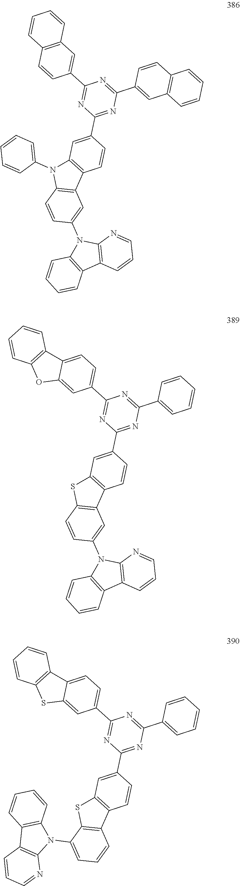
Optionally, the heterocyclic compound is selected from the following compounds:
Figure US11873311-20240116-C00032
Figure US11873311-20240116-C00033
Figure US11873311-20240116-C00034
Figure US11873311-20240116-C00035
Figure US11873311-20240116-C00036
Figure US11873311-20240116-C00037
Figure US11873311-20240116-C00038
Figure US11873311-20240116-C00039
Figure US11873311-20240116-C00040
Figure US11873311-20240116-C00041
Figure US11873311-20240116-C00042
Figure US11873311-20240116-C00043
Figure US11873311-20240116-C00044
Figure US11873311-20240116-C00045
Figure US11873311-20240116-C00046
Figure US11873311-20240116-C00047
Figure US11873311-20240116-C00048
Figure US11873311-20240116-C00049
Figure US11873311-20240116-C00050
Figure US11873311-20240116-C00051
Figure US11873311-20240116-C00052
Figure US11873311-20240116-C00053
Figure US11873311-20240116-C00054
Figure US11873311-20240116-C00055
Figure US11873311-20240116-C00056
Figure US11873311-20240116-C00057
Figure US11873311-20240116-C00058
Figure US11873311-20240116-C00059
Figure US11873311-20240116-C00060
Figure US11873311-20240116-C00061
Figure US11873311-20240116-C00062
Figure US11873311-20240116-C00063
Figure US11873311-20240116-C00064
Figure US11873311-20240116-C00065
Figure US11873311-20240116-C00066
Figure US11873311-20240116-C00067
Figure US11873311-20240116-C00068
Figure US11873311-20240116-C00069
Figure US11873311-20240116-C00070
Figure US11873311-20240116-C00071
Figure US11873311-20240116-C00072
Figure US11873311-20240116-C00073
Figure US11873311-20240116-C00074
Figure US11873311-20240116-C00075
Figure US11873311-20240116-C00076
Figure US11873311-20240116-C00077
Figure US11873311-20240116-C00078
Figure US11873311-20240116-C00079
Figure US11873311-20240116-C00080
Figure US11873311-20240116-C00081
Figure US11873311-20240116-C00082
Figure US11873311-20240116-C00083
Figure US11873311-20240116-C00084
Figure US11873311-20240116-C00085
Figure US11873311-20240116-C00086
Figure US11873311-20240116-C00087
Figure US11873311-20240116-C00088
Figure US11873311-20240116-C00089
Figure US11873311-20240116-C00090
Figure US11873311-20240116-C00091
Figure US11873311-20240116-C00092
Figure US11873311-20240116-C00093
Figure US11873311-20240116-C00094
Figure US11873311-20240116-C00095
Figure US11873311-20240116-C00096
Figure US11873311-20240116-C00097
Figure US11873311-20240116-C00098
Figure US11873311-20240116-C00099
Figure US11873311-20240116-C00100
Figure US11873311-20240116-C00101
Figure US11873311-20240116-C00102
Figure US11873311-20240116-C00103
Figure US11873311-20240116-C00104
Figure US11873311-20240116-C00105
Figure US11873311-20240116-C00106
Figure US11873311-20240116-C00107
Figure US11873311-20240116-C00108
Figure US11873311-20240116-C00109
Figure US11873311-20240116-C00110
Figure US11873311-20240116-C00111
Figure US11873311-20240116-C00112
Figure US11873311-20240116-C00113
Figure US11873311-20240116-C00114
Figure US11873311-20240116-C00115
Figure US11873311-20240116-C00116
Figure US11873311-20240116-C00117
Figure US11873311-20240116-C00118
Figure US11873311-20240116-C00119
Figure US11873311-20240116-C00120
Figure US11873311-20240116-C00121
Figure US11873311-20240116-C00122
Figure US11873311-20240116-C00123
Figure US11873311-20240116-C00124
Figure US11873311-20240116-C00125
Figure US11873311-20240116-C00126
Figure US11873311-20240116-C00127
Figure US11873311-20240116-C00128
Figure US11873311-20240116-C00129
Figure US11873311-20240116-C00130
Figure US11873311-20240116-C00131
Figure US11873311-20240116-C00132
Figure US11873311-20240116-C00133
Figure US11873311-20240116-C00134
Figure US11873311-20240116-C00135
Figure US11873311-20240116-C00136
Figure US11873311-20240116-C00137
Figure US11873311-20240116-C00138
Figure US11873311-20240116-C00139
Figure US11873311-20240116-C00140
Figure US11873311-20240116-C00141
Figure US11873311-20240116-C00142
Figure US11873311-20240116-C00143
Figure US11873311-20240116-C00144
Figure US11873311-20240116-C00145
Figure US11873311-20240116-C00146
Figure US11873311-20240116-C00147
Figure US11873311-20240116-C00148
Figure US11873311-20240116-C00149
Figure US11873311-20240116-C00150
Figure US11873311-20240116-C00151
Figure US11873311-20240116-C00152
Figure US11873311-20240116-C00153
Figure US11873311-20240116-C00154
Figure US11873311-20240116-C00155
Figure US11873311-20240116-C00156
Figure US11873311-20240116-C00157
The synthetic methods of the heterocyclic compound provided by the discloser are not specially limited, and those skilled in the art can determine a proper synthetic method according to the heterocyclic compounds provided by the disclosure in combination with the preparation methods in the examples. In other words, the examples of the discloser exemplarily provide the preparation methods of the heterocyclic compounds, and the adopted raw materials can be obtained commercially or obtained by the methods well known in the field. All the heterocyclic compounds provided by the disclosure can be obtained by those skilled in the art according to the preparation methods in these exemplary examples, all specific preparation methods for preparing the heterocyclic compounds are no longer described in detail, and those skilled in the art should not be understood as limiting the discloser.
The discloser further provides an organic electroluminescent device. As shown in FIG. 1 , the organic electroluminescent device includes an anode 100 and a cathode 200 which are oppositely arranged, and a functional layer arranged between the anode 100 and the cathode 200; the functional layer includes the heterocyclic compound provided by the discloser. The heterocyclic compound provided by the discloser can be used for forming at least one organic thin layer of the functional layer so as to improve the service life characteristic and the efficiency characteristic of the organic electroluminescent device. The organic electroluminescent device may be a blue light device or a green light device.
Optionally, the functional layer includes an organic light-emitting layer 330, and the organic light-emitting layer 330 contains the heterocyclic compound provided by the discloser.
According to one embodiment, as shown in FIG. 1 , the organic electroluminescent device includes an anode 100, a hole transporting layer 321, an organic light-emitting layer 330, an electron transporting layer 340 and a cathode 200 which are sequentially stacked. The heterocyclic compound provided by the discloser may be applied to the organic light-emitting layer 330 of the organic electroluminescent device, so that the service life of the organic electroluminescent device is prolonged, and the luminous efficiency of the organic electroluminescent device is improved.
Optionally, the anode 100 includes an anode material, which is preferably a material with a large work function that facilitates hole injection into the functional layer. Specific examples of the anode material include, but are not limited to, metals such as nickel, platinum, vanadium, chromium, copper, zinc and gold, or an alloy thereof; metal oxides such as zinc oxide, indium oxide, indium tin oxide (ITO) and indium zinc oxide (IZO); combinations of metals and oxides, such as ZnO: Al or SnO2:Sb; or a conductive polymer such as poly(3-methylthiophene), poly[3,4-(ethylene-1,2-dioxy)thiophene] (PEDT), polypyrrole and polyaniline. A transparent electrode containing indium tin oxide (ITO) as the anode is preferably included.
Optionally, the hole transporting layer 321 includes one or more hole transporting materials. The hole transporting materials may be selected from carbazole polymers, carbazole-connected triarylamine compounds, or other types of compounds, which are not specially limited in the present discloser.
Optionally, the organic light-emitting layer 330 includes a host material and a guest material, holes injected into the organic light-emitting layer 330 and electrons injected into the organic light-emitting layer 330 may be recombined in the organic light-emitting layer 330 to form excitons, the excitons transfer energy to the host material, then the host material transfers energy to the guest material, so that the guest material can emit light. The host material of the organic light-emitting layer 330 may be composed of the heterocyclic compound of the present discloser. The guest material of the organic light-emitting layer 330 may be a compound having a condensed aryl ring or a derivative thereof, a compound having a heteroaryl ring or a derivative thereof, an aromatic amine derivative, or other materials, which is not specially limited in the discloser.
Optionally, the electron transporting layer 340 is a single-layer structure or a multi-layer structure, and it include one or more electron transporting materials. The electron transporting materials may be selected from, but are not limited to, a benzimidazole derivative, an oxadiazole derivative, a quinoxaline derivative, or other electron transporting materials.
Optionally, the cathode 200 includes a cathode material, which is a material with a small work function that contributes to electron injection into the functional layer. Specific examples of the cathode materials include, but are not limited to, metals such as magnesium, calcium, sodium, potassium, titanium, indium, yttrium, lithium, gadolinium, aluminum, silver, tin and lead, or an alloy thereof; or multilayer materials such as LiF/Al, Liq/Al, LiO2/Al, LiF/Ca, LiF/Al, and BaF2/Ca. A metal electrode containing aluminum as the cathode is preferably included. In one embodiment of the present discloser, the material of the cathode 200 is a magnesium-silver alloy.
Optionally, as shown in FIG. 1 , a hole injecting layer 310 is also be arranged between the anode 100 and the hole transporting layer 321, so that the capability of injecting holes into the hole transporting layer 321 is enhanced. The hole injecting layer 310 may be made of a benzidine derivative, a starburst arylamine compound, a phthalocyanine derivative, or other materials, which is not specially limited in the present discloser.
Optionally, as shown in FIG. 1 , an electron blocking layer 322 is also be arranged between the hole transporting layer 321 and the organic light-emitting layer 330 so as to block electrons from being transported to the side of the hole transporting layer 321, improve the recombination rate of the electrons and holes in the organic light-emitting layer 330 and protect the hole transporting layer 321 from being impacted by the electrons. The material of the electron blocking layer 322 may be carbazole polymers, carbazole-connected triarylamine compounds, or other feasible structures.
Optionally, as shown in FIG. 1 , an electron injecting layer 350 is also be arranged between the cathode 200 and the electron transporting layer 340 so as to enhance the capability of injecting electrons into the electron transporting layer 340. The electron injecting layer 350 may include an inorganic material such as an alkali metal sulfide and an alkali metal halide, or may include a complex of an alkali metal and an organic substance.
The discloser also provides an electronic device 400, as shown in FIG. 2 , the electronic device 400 includes any one of the organic electroluminescent devices described in the above embodiments of the organic electroluminescent device. The electronic device 400 may be a display device, a lighting device, an optical communication device, or other types of electronic devices, and may include, for example, but is not limited to, a computer screen, a mobile phone screen, a television, an electronic paper, an emergency lighting lamp, an optical module and the like. Since the electronic device 400 is provided with any organic electroluminescent device described in the above embodiments of the organic electroluminescent device, the electronic device 400 has the same beneficial effects, which will not be repeated here.
The present disclosure is further described in detail below by examples. However, the following examples are merely illustrative of the disclosure, and are not intended to limit the disclosure.
Synthesis Example 1: Synthesis of Compound 6
Figure US11873311-20240116-C00158
    • (1) Nitrogen (0.100 L/min) was introduced into a three-necked flask provided with a mechanical stirrer, a thermometer and a condenser tube for replacement for 15 min, and Raw material 6d (50 mmol), Raw material 6c (37.5 mmol), potassium carbonate (100 mmol), 18-crown-6-ether (6 mmol), 1,10-phenanthroline (6 mmol), cuprous iodide (12 mmol) and 125 mL of xylene were sequentially added. Stirring was started, the temperature was raised to 130° C. to 135° C. to react for 7 h, then 125 mL of toluene and 125 mL of water were added into the reaction solution under stirring, liquid separation was performed, and the water phase was extracted once with 125 mL of methylbenzene. Organic phases were mixed, and washed with water twice, dried over 5 g of anhydrous sodium sulfate, filtered, and concentrated (50° C. to 60° C., −0.09 MPa to −0.08 MPa) until no liquid drops flowed out, 30 mL of ethanol was added while stirring, and filtering was performed to obtain Intermediate 6-1 (24 mmol, yield: 64%).
Figure US11873311-20240116-C00159
    • (2) Nitrogen (0.100 L/min) was introduced into a three-necked flask provided with a mechanical stirrer, a thermometer and a constant-pressure dropping funnel for replacement for 15 min, Intermediate 6-1 (24 mmol) and 60 mL of tetrahydrofuran were added, stirring was started, cooling was performed with liquid nitrogen to −90° C. to −80° C., 2 mol/L n-hexane solution of n-butyllithium (28 mmol) was dropwise added, the temperature was kept for 1 hour after dropwise adding, tributyl borate (32 mmol) was dropwise added, the temperature was kept for 1 hour after dropwise adding, 150 mL of water, 30.00 mL of petroleum ether and 2.4 mL of concentrated hydrochloric acid were added into the reaction solution, full stirring was performed, liquid separation was performed, and the organic phase was washed with water for 4 times, then filtered to obtain a crude product, pulping was performed with 24.0 mL of toluene for 0.5 h, filtering was performed, and drip washing was performed with toluene to obtain Intermediate 6-2 (15 mmol, yield: 63%).
Figure US11873311-20240116-C00160
    • (3) Nitrogen (0.100 L/min) was introduced into a three-necked reaction flask provided with a mechanical stirrer, a thermometer and a condenser tube for replacement for 15 min, Raw material 6e (15 mmol), Intermediate 6-2 (15 mmol), potassium carbonate (30 mmol), tetrakis(triphenylphosphine)palladium (0.15 mmol), 35 mL of toluene and 15 mL of water were added, stirring was started, heating was performed to 65° C. to 70° C., and the reaction was carried out for 4 h while heat preservation, 35 mL of water was added into the reaction solution while stirring, standing and liquid separation were performed, the water phase was extracted once with 35 mL of toluene, liquid separation was performed, and the organic phases were mixed, then washed twice with 35 mL of water. 5 g of anhydrous sodium sulfate was added into the organic phase for drying, filtering was performed, the organic phase was concentrated (−0.08 MPa to −0.09 MPa, 55° C. to 65° C.) until no liquid flowed out, 15 mL of petroleum ether was added while stirring, and filtering was performed to obtain the compound 6 (7.49 g, yield: 830%), m/z=602.3 [M+H]+.
Synthesis Examples 2 to 7
According to the method in Synthesis example 1, compounds listed in Table 1 were synthesized respectively, except that Raw material 6d and Raw material 6e were replaced with Raw material Id and Raw material e respectively, and the adopted main raw materials, the structures of the synthesized compounds, the total yield of the compounds in the whole process and the mass spectrum result are shown in Table 1.
TABLE 1
Mass
Synthesis spectrum
example Compound Raw material Raw material Compound Yield, (m/z),
No. No. Id Ie structure % [M + H]+
2 10
Figure US11873311-20240116-C00161
Figure US11873311-20240116-C00162
Figure US11873311-20240116-C00163
33 592.5
3 18
Figure US11873311-20240116-C00164
Figure US11873311-20240116-C00165
Figure US11873311-20240116-C00166
39 576.6
4 50
Figure US11873311-20240116-C00167
Figure US11873311-20240116-C00168
Figure US11873311-20240116-C00169
35 665.2
5 66
Figure US11873311-20240116-C00170
Figure US11873311-20240116-C00171
Figure US11873311-20240116-C00172
31 543.5
6 77
Figure US11873311-20240116-C00173
Figure US11873311-20240116-C00174
Figure US11873311-20240116-C00175
33 651.3
7 81
Figure US11873311-20240116-C00176
Figure US11873311-20240116-C00177
Figure US11873311-20240116-C00178
34 724.6
Synthesis of Intermediate I
Figure US11873311-20240116-C00179
    • (1) Nitrogen (0.100 L/min) was introduced into a three-necked flask provided with a mechanical stirrer, a thermometer and a condenser tube for replacement for 15 min, and Raw material 1-1 (8.4 g, 50 mmol), Raw material 1-2 (16.8 g, 55 mmol), potassium carbonate (13.8 g, 100 mmol), 18-crown-6-ether (1.3 g, 5 mmol), 1,10-phenanthroline (1.0 g, 5 mmol), cuprous iodide (1.9 g, 10 mmol) and 130 mL of xylene were sequentially added. Stirring was started, the temperature was raised to 130° C. to 135° C. to react for 10 h. 130 mL of toluene and 130 mL of water were added into the reaction solution while stirring, liquid separation was performed, and the water phase was extracted once with 130 mL of toluene. The organic phases were mixed, and then washed with water twice, dried over 5 g of anhydrous sodium sulfate, filtered, and concentrated (50° C. to 60° C., −0.09 MPa to −0.08 MPa) until no liquid drops flowed out, 25 mL of ethanol was added while stirring, and filtering was performed to obtain Intermediate 1-3 (15.8 g, yield: 80%).
Figure US11873311-20240116-C00180
    • (2) Nitrogen (0.100 L/min) was introduced into a three-necked flask provided with a mechanical stirrer and a thermometer for replacement for 15 min, Intermediate 1-3 (15.8 g, 40 mmol), pinacol diborate (12.2 g, 48 mmol), potassium acetate (7.9 g, 80 mmol) and 80 mL of 1,4-dioxane were sequentially added, stirring was started, heating was performed to 60° C. to 65° C., bis(tricyclohexylphosphine)palladium dichloride (0.30 g, 0.4 mmol) was added, heating was continuously performed to 85° C. to 90° C., the temperature was kept for 5 h, then 60 mL of water was added, extraction was performed with 100 mL of dichloromethane, the water phase was extracted with 30 mL of dichloromethane, and the organic phases were mixed, washed with water twice, dried over 2 g of anhydrous sodium sulfate, filtered, and concentrated (40° C. to 45° C., −0.06 MPa to −0.05 MPa) until no liquid flowed out, 20 mL of cyclohexane was added, and filtering was performed to obtain Intermediate 1 (15.1 g, yield: 77.5%).
    • 2. Intermediates shown in Table 2 were synthesized according to the synthesis method of Intermediate 1, except that Raw material I-2 was used to replace Raw material 1-2, and Raw material I-2, the structures of the intermediates and the total yield are shown in Table 2.
TABLE 2
Inter- Total
mediate Raw yield,
I No. material 1-1 Raw material I-2 Structure of Intermediate I %
Inter- mediate 2
Figure US11873311-20240116-C00181
Figure US11873311-20240116-C00182
Figure US11873311-20240116-C00183
58.7
Inter- mediate 3
Figure US11873311-20240116-C00184
Figure US11873311-20240116-C00185
Figure US11873311-20240116-C00186
55.3
Inter- mediate 4
Figure US11873311-20240116-C00187
Figure US11873311-20240116-C00188
Figure US11873311-20240116-C00189
60.5
Inter- mediate 5
Figure US11873311-20240116-C00190
Figure US11873311-20240116-C00191
Figure US11873311-20240116-C00192
62.8
Inter- mediate 6
Figure US11873311-20240116-C00193
Figure US11873311-20240116-C00194
Figure US11873311-20240116-C00195
59.7
Inter- mediate 7
Figure US11873311-20240116-C00196
Figure US11873311-20240116-C00197
Figure US11873311-20240116-C00198
56.8
Inter- mediate 8
Figure US11873311-20240116-C00199
Figure US11873311-20240116-C00200
Figure US11873311-20240116-C00201
55.9
Inter- mediate 9
Figure US11873311-20240116-C00202
Figure US11873311-20240116-C00203
Figure US11873311-20240116-C00204
58.7
Synthesis Example 8: Synthesis of Compound 95
Figure US11873311-20240116-C00205
Nitrogen (0.100 L/min) was introduced into a three-necked reaction flask provided with a mechanical stirrer, a thermometer and a condenser tube for replacement for 15 min, Intermediate 1 (9.7 g, 20 mmol), Raw material 95a (7.2 g, 21 mmol), potassium carbonate (5.5 g, 40 mmol), tetrakis(triphenylphosphine)palladium (0.23 g, 0.2 mmol), 50 mL of methylbenzene and 20 mL of water were added, stirring was started, heating was performed to 65° C. to 70° C., and the reaction was carried out for 4 h while heat preservation, 50 mL of water was added into the reaction solution while stirring, standing and liquid separation were performed, the water phase was extracted once with 50 mL of toluene, liquid separation was performed, and the organic phases were mixed, washed twice with 50 mL of water. 5 g of anhydrous sodium sulfate was added into the organic phase for drying, filtering was performed, the organic phase was concentrated (−0.08 MPa to −0.09 MPa, 55° C. to 65° C.) until no liquid flowed out, 20 mL of ethanol was added while stirring, and filtering was performed to obtain the compound 95 (12.0 g, yield: 90.0%), m/z=668.3 [M+H]+. NMR of the compound 95: 1H-NMR (CDCl3, 400 MHz) δ ppm: 8.71-8.68 (m, 2H), 8.45-8.41 (m, 3H), 8.21-8.17 (m, 2H), 8.06-8.02 (m, 3H), 7.93 (s, 1H), 7.81-7.77 (m, 3H), 7.70 (s, 1H), 7.62-7.56 (m, 6H), 7.50-7.48 (m, 1H), 7.43-7.40 (m, 1H), 7.30-7.26 (dd, 2H), 7.19-7.15 (m, 2H), 2.54 (s, 6H).
Synthesis Examples 9-30
Compounds shown in Table 3 were synthesized by referring to the synthesis method in synthesis example 8, except that the intermediate I was used to replace the intermediate 1, a raw material Ia was used to replace the raw material 95, and the adopted main raw materials, the yield of the compounds and a mass spectrum result are shown in Table 3.
TABLE 3
Mass
Synthesis spectrum
example Compound Raw material Yield, (m/z),
No. No. Ia Intermediate I Compound structure % [M + H]+
 9  31
Figure US11873311-20240116-C00206
Figure US11873311-20240116-C00207
Figure US11873311-20240116-C00208
88.5 712.3
10  34
Figure US11873311-20240116-C00209
Figure US11873311-20240116-C00210
Figure US11873311-20240116-C00211
91.5 587.3
11  98
Figure US11873311-20240116-C00212
Figure US11873311-20240116-C00213
Figure US11873311-20240116-C00214
82.4 744.3
12 103
Figure US11873311-20240116-C00215
Figure US11873311-20240116-C00216
Figure US11873311-20240116-C00217
81.1 682.4
13 110
Figure US11873311-20240116-C00218
Figure US11873311-20240116-C00219
Figure US11873311-20240116-C00220
84.5 682.7
14 118
Figure US11873311-20240116-C00221
Figure US11873311-20240116-C00222
Figure US11873311-20240116-C00223
85.7 642.6
15 131
Figure US11873311-20240116-C00224
Figure US11873311-20240116-C00225
Figure US11873311-20240116-C00226
86.2 744.5
16 187
Figure US11873311-20240116-C00227
Figure US11873311-20240116-C00228
Figure US11873311-20240116-C00229
87.4 668.3
17 209
Figure US11873311-20240116-C00230
Figure US11873311-20240116-C00231
Figure US11873311-20240116-C00232
82.9 682.3
18 222
Figure US11873311-20240116-C00233
Figure US11873311-20240116-C00234
Figure US11873311-20240116-C00235
88.6 744.5
19 229
Figure US11873311-20240116-C00236
Figure US11873311-20240116-C00237
Figure US11873311-20240116-C00238
89.5 666.2
20 230
Figure US11873311-20240116-C00239
Figure US11873311-20240116-C00240
Figure US11873311-20240116-C00241
84.6 594.2
21 243
Figure US11873311-20240116-C00242
Figure US11873311-20240116-C00243
Figure US11873311-20240116-C00244
85.6 566.3
22 253
Figure US11873311-20240116-C00245
Figure US11873311-20240116-C00246
Figure US11873311-20240116-C00247
83.8 566.2
23 306
Figure US11873311-20240116-C00248
Figure US11873311-20240116-C00249
Figure US11873311-20240116-C00250
83.4 672.4
24 321
Figure US11873311-20240116-C00251
Figure US11873311-20240116-C00252
Figure US11873311-20240116-C00253
80.9 682.2
25 359
Figure US11873311-20240116-C00254
Figure US11873311-20240116-C00255
Figure US11873311-20240116-C00256
81.6 698.5
26 360
Figure US11873311-20240116-C00257
Figure US11873311-20240116-C00258
Figure US11873311-20240116-C00259
88.4 641.3
27 361
Figure US11873311-20240116-C00260
Figure US11873311-20240116-C00261
Figure US11873311-20240116-C00262
85.7 717.2
28 362
Figure US11873311-20240116-C00263
Figure US11873311-20240116-C00264
Figure US11873311-20240116-C00265
87.6 691.1
29 393
Figure US11873311-20240116-C00266
Figure US11873311-20240116-C00267
Figure US11873311-20240116-C00268
85.4 672.3
30 394
Figure US11873311-20240116-C00269
Figure US11873311-20240116-C00270
Figure US11873311-20240116-C00271
86.6 688.5
31 395
Figure US11873311-20240116-C00272
Figure US11873311-20240116-C00273
Figure US11873311-20240116-C00274
86.9 688.3
NMR of the compound 229: 1H-NMR (CDCl3, 400 MHz) δ ppm: 9.12 (s, 1H), 9.07 (s, 1H), 8.59-8.56 (m, 2H), 8.53-8.50 (m, 2H), 8.45-8.43 (d, 1H), 8.27-8.24 (m, 2H), 8.18-8.15 (m, 3H), 8.11-8.06 (m, 5H), 7.69-7.65 (m, 4H), 7.62-7.59 (m, 2H), 7.38-7.34 (m, 2H), 7.25-7.21 (m, 2H).
Figure US11873311-20240116-C00275
Nitrogen (0.100 L/min) was introduced into a three-necked flask provided with a mechanical stirrer, a thermometer and a constant-pressure dropping funnel for replacement for 15 min, 6-bromo-2-chloro-9,9-dimethyl-9H-fluorene (15.3 g, 50 mmol) and 100 mL of tetrahydrofuran were added, stirring was started, cooling was performed with liquid nitrogen to −90° C. to −80° C., 2 mol/L n-hexane solution of n-butyllithium (60 mmol) was dropwise added, the temperature was kept for 1 hour after dropwise adding, tributyl borate (15.0 g, 65.2 mmol) was dropwise added, the temperature was kept for 1 hour after dropwise adding, 200 mL of water, 40 mL of petroleum ether and 3 mL of concentrated hydrochloric acid were added into the reaction solution, full stirring was performed, liquid separation was performed, the organic phase was washed with water for 4 times, and filtered to obtain a crude product, pulping was performed with 50.0 mL of toluene for 0.5 h, and filtering was performed to obtain Intermediate II (9.7 g, yield: 71%).
Synthesis Example 32: Synthesis of Compound 168
Figure US11873311-20240116-C00276
    • (1) Nitrogen (0.100 L/min) was introduced into a three-necked reaction flask provided with a mechanical stirrer, a thermometer and a condenser tube for replacement for 15 min, Intermediate II (8.2 g, 30 mmol), Raw material 168c (11.5 g, 30 mmol), potassium carbonate (8.3 g, 60 mmol), tetrakis(triphenylphosphine)palladium (0.35 g, 0.3 mmol), 60 mL of toluene and 20 mL of water were added, stirring was started, heating was performed to 65° C. to 70° C., and the reaction was carried out for 5 h while heat preservation, 50 mL of water was added into the reaction solution while stirring, standing and liquid separation were performed, the water phase was extracted once with 50 mL of toluene, liquid separation was performed, the organic phases were mixed and washed twice with 50 mL of water. 5 g of anhydrous sodium sulfate was added into the organic phase for drying, filtering was performed, the organic phase was concentrated (−0.08 MPa to −0.0 MPa, 55° C. to 65° C.) until no liquid flowed out, 20 mL of cyclohexane was added while stirring, and filtering was performed to obtain Intermediate 168d (13.8 g, yield: 80.0%).
Figure US11873311-20240116-C00277
    • (2) Nitrogen (0.100 L/min) was introduced into a three-necked flask provided with a mechanical stirrer, a thermometer and a condenser tube for replacement for 15 min, Intermediate 168d (11.5 g, 20 mmol), 9H-pyrido[2,3-B]indole (3.7 g, 22 mmol), potassium carbonate (5.5 g, 40 mmol), 18-crown-6-ether (0.5 g, 2 mmol), 1,10-phenanthroline (0.4 g, 2 mmol), cuprous iodide (0.8 g, 4 mmol) and 60 mL of xylene were sequentially added, stirring was started, the temperature was raised to 130° C. to 135° C. to react for 15 h. 80 mL of toluene and 80 mL of water were added into the reaction solution while stirring, liquid separation was performed, and the water phase was extracted once with 50 mL of toluene, the organic phases were mixed and washed with water twice, dried over 5 g of anhydrous sodium sulfate, filtered, and concentrated (50° C. to 60° C., −0.09 MPa to −0.08 MPa) until no liquid drops flowed out, 15 mL of ethanol was added while stirring, and filtering was performed to obtain the compound 168 (8.5 g, yield: 60%), m/z=708.3 [M+H]+.
Synthesis Examples 33 to 34
The compound 178 and the compound 171 were respectively synthesized by referring to the method in Synthesis example 32, except that Raw material 168c was replaced by Raw material Ic, and Raw material Ic, the total yield of the compounds and the mass spectrum result are shown in Table 4.
TABLE 4
Mass
Synthesis spectrum
example Compound Total (m/z),
No. No. Raw material Ic Compound structure yield, % [M + H]+
33 178
Figure US11873311-20240116-C00278
Figure US11873311-20240116-C00279
42.9 708.3
34 171
Figure US11873311-20240116-C00280
Figure US11873311-20240116-C00281
46.1 642.3
Manufacturing of an organic electroluminescent device
Example 1
The manufacturing method of the organic electroluminescent device includes the following steps:
    • (1) firstly, a glass bottom plate with an indium tin oxide (ITO) electrode of 1500 Å was ultrasonically cleaned by using distilled water and methanol sequentially, and dried;
    • (2) then cleaning was performed for 5 min by using oxygen plasma, and the cleaned anode base plate was loaded into vacuum deposition equipment;
    • (3) compound 2T-NATA (CAS: 185690-41-9) was vacuum deposited on the ITO electrode to form a hole injecting layer with a thickness of 500 Å, then NPB (CAS: 123847-85-8) was vacuum deposited on the hole injecting layer to form a hole transporting layer with a thickness of 800 Å, and TQTPA (CAS: 1142945-07-0) was evaporated on the hole transporting layer to form an electron blocking layer with a thickness of 200 Å. Then, the compound 6 serving as a light-emitting host material and a dopant BNP3FL (CAS: 669016-17-5) serving as a guest material were co-deposited on the electron blocking layer at a film thickness ratio of 100:3 to form an organic light-emitting layer with a thickness of 300 Å;
    • (4) TPBi was vacuum deposited on the light-emitting layer to form a hole blocking layer with a thickness of 200 Å; and
    • (5) DBimiBphen and LiQ was mixed at a weight ratio of 1:1, and the mixture was vacuum deposited on the hole blocking layer to form an electron transporting layer with a thickness of 300 Å. Then LiQ was evaporated on the electron transporting layer to form an electron injecting layer with a thickness of 15 Å, then magnesium (Mg) and silver (Ag) were mixed at an evaporation rate of 1:9, and the mixture was vacuum-evaporated on the electron injecting layer to form a cathode with a thickness of 120 Å.
Finally, CP-1 was evaporated on the cathode to form a covering layer (CPL) with a thickness of 650 Å, thereby completing the manufacturing of the organic light-emitting device. The structures of TPBi, DBimiBphen, LiQ and CP-1 are as follows:
Figure US11873311-20240116-C00282
Examples 2 to 9
The organic electroluminescent device was manufactured by adopting the same method as in Example 1, except that in Examples 2 to 9, the compounds shown in Table 5 were used to replace the compound 6 to serve as host material to manufacture the organic electroluminescent device.
Comparative Examples 1 to 4
In comparative examples 1 to 4, the organic electroluminescent device was manufactured by using the same method as in Example 1, except that DMFL-CBP, a compound A, a compound B, and a compound C were used respectively as a host material of the organic light-emitting layer to replace the compound 6. The structural formulas of DMFL-CBP, the compound A, the compound B and the compound C are as follows:
Figure US11873311-20240116-C00283
The T95 service life of the prepared organic electroluminescent devices was tested under the condition of 15 mA/cm2, and data such as the voltage, the efficiency and the chromaticity coordinate of the prepared organic electroluminescent device were tested under a constant current density of 10 mA/cm2, and the result is shown in Table 5.
TABLE 5
External
Operating Current quantum Chromaticity Service
voltage efficiency efficiency coordinate life
No. Host material (V) (Cd/A) (EQE) (CIEy) T95 (h)
Example 1 Compound 6 3.9 6.8 12.6 0.054 258
Example 2 Compound 10 4.0 6.6 12.8 0.051 256
Example 3 Compound 18 3.9 6.1 11.6 0.053 213
Example 4 Compound 31 3.9 6.4 12.3 0.051 234
Example 5 Compound 34 3.9 6.2 11.9 0.050 238
Example 6 Compound 50 3.8 6.7 12.4 0.051 215
Example 7 Compound 66 3.9 6.3 12.1 0.054 209
Example 8 Compound 77 3.9 6.6 11.6 0.053 249
Example 9 Compound 81 3.9 6.7 13.0 0.051 218
Comparative DMFL-CBP 4.2 5.3 10.6 0.052 168
example 1
Comparative Compound A 4.1 5.0 10.2 0.050 159
example 2
Comparative Compound B 3.9 5.8 10.8 0.052 198
example 3
Comparative Compound C 3.9 5.9 11.0 0.051 184
example 4
It can be seen from Table 5 that the current efficiency of the organic electroluminescent devices prepared in examples 1 to 9 is at least improved by 3.4% compared with that of the organic electroluminescent devices prepared in comparative examples 1 to 4, and the external quantum efficiency is at least improved by 5.5% compared with that in comparative examples. The T95 service life in examples 1 to 9 is at least 5.6% longer than the T95 service life in comparative examples 1 to 4. In addition, the devices in examples 1 to 9 also have relatively low driving voltage.
Example 10
An ITO substrate (manufactured by Corning) with an ITO thickness of 1500 Å was cut into a size of 40 mm (length)×40 mm (width)×0.7 mm (thickness) to be prepared into an experimental substrate with a cathode, an anode and an insulating layer pattern by adopting a photoetching process, and surface treatment was performed by utilizing ultraviolet ozone and O2:N2 plasma so as to increase the work function of the anode (the experimental substrate) and remove scum.
m-MTDATA was vacuum-evaporated on the experiment substrate (the anode) to form a hole injecting layer with a thickness of 100 Å, and NPB was evaporated on the hole injecting layer to form a hole transporting layer with a thickness of 1000 Å.
EB-1 was evaporated on the hole transporting layer to form an electron blocking layer with a thickness of 400 Å.
The compound 95 as a host material was evaporated on the hole blocking layer and doped with Jr(ppy)3, which served as a guest material, at a film thickness ratio of 100:3 to from an organic light-emitting layer with a thickness of 330 Å.
ET-1 and LiQ were mixed at a weight ratio of 1:1, and the mixture was evaporated to form an electron transporting layer with a thickness of 280 Å, LiQ was evaporated on the electron transporting layer to form an electron injecting layer with a thickness of 13 Å, then magnesium (Mg) and silver (Ag) were mixed at an evaporation rate of 1:9, and the mixture was vacuum-evaporated on the electron injecting layer to form a cathode with a thickness of 105 Å.
In addition, CP-1 with a thickness of 700 Å was evaporated on the cathode to form an organic capping layer (CPL), thereby completing manufacturing of the organic light-emitting device. The structures of the above main materials used for preparing the device are as follows:
Figure US11873311-20240116-C00284
Figure US11873311-20240116-C00285
Examples 11 to 34
In addition to using compounds shown in Table 6 as a light-emitting host when the organic light-emitting layer was formed, the organic electroluminescent device was manufactured by the same method as in Example 10.
Comparative Examples 5 to 6
In the comparative examples 5 to 6, a compound D and a compound E were respectively used to replace the compound 95, the organic electroluminescent device was manufactured by adopting the same method as in Example 10, and the structural formulas of the compound D and the compound E are as follows:
Figure US11873311-20240116-C00286
The T95 service life of the prepared organic electroluminescent device was tested under the condition of 15 mA/cm2, and the driving voltage, the efficiency and the chromaticity coordinate of the prepared organic electroluminescent device were tested under the constant current density of 10 mA/cm2, and the result is shown in Table 6.
TABLE 6
External
Operating Current Chromaticity quantum T95
Light-emitting voltage efficiency coordinate efficiency service
No. host material (V) Cd/A CIEx, CIEy EQE % life (h)
Example 10 Compound 95 3.85 81.23 0.263, 0.700 21.60 556
Example 11 Compound 98 3.76 80.57 0.261, 0.702 20.90 534
Example 12 Compound 3.88 81.23 0.262, 0.701 21.57 565
103
Example 13 Compound 3.90 79.34 0.259, 0.700 20.09 534
110
Example 14 Compound 3.74 78.68 0.260, 0.704 19.94 526
118
Example 15 Compound 3.83 77.14 0.261, 0.701 18.12 527
131
Example 16 Compound 3.79 81.26 0.261, 0.701 21.71 573
168
Example 17 Compound 3.79 80.24 0.261, 0.701 20.74 521
171
Example 18 Compound 3.81 78.56 0.260, 0.703 19.86 524
178
Example 19 Compound 3.81 81.45 0.258, 0.700 21.67 507
187
Example 20 Compound 3.74 80.45 0.262, 0.703 20.83 557
209
Example 21 Compound 3.85 81.83 0.262, 0.702 21.89 576
222
Example 22 Compound 3.82 79.56 0.259, 0.699 20.16 557
229
Example 23 Compound 3.84 80.58 0.259, 0.702 20.91 541
230
Example 24 Compound 3.80 80.21 0.258, 0.701 20.84 586
243
Example 25 Compound 3.78 78.68 0.260, 0698 20.51 537
253
Example 26 Compound 3.71 79.41 0.262, 0.701 20.11 581
306
Example 27 Compound 3.92 70.24 0.261, 0.697 18.08 462
321
Example 28 Compound 3.96 68.24 0.259, 0.700 17.81 443
359
Example 29 Compound 3.90 67.54 0.258, 0.697 17.79 433
360
Example 30 Compound 3.96 69.21 0.260, 0.703 18.00 485
361
Example 31 Compound 3.94 66.24 0.263, 0.697 17.55 471
362
Example 32 Compound 3.92 68.35 0.262, 0.701 17.84 468
393
Example 33 Compound 3.91 68.54 0.264, 0.702 17.89 456
394
Example 34 Compound 3.94 66.48 0.259, 0.700 17.60 450
395
Comparative Compound D 4.00 57.23 0.264, 0.702 15.57 357
example 5
Comparative Compound E 4.13 55.21 0.262, 0.701 14.25 335
example 6
In combination with a result shown in Table 6, it can be seen that comparing with that of the comparative examples 5 to 6, the current efficiency of the organic electroluminescent devices prepared in examples 10 to 34 is at least improved by 15.7%, the external quantum efficiency is at least improved by 12.7%, and the T95 service life is at least improved by 21.3%.
Therefore, compared with the devices in the comparative examples, the organic electroluminescent devices prepared in examples 1 to 34 have higher luminous efficiency and higher external quantum efficiency, the service life characteristic of the device is also obviously improved, and meanwhile, the organic electroluminescent device also has lower driving voltage.
Therefore, the heterocyclic compound provided by the discloser can be applied to the organic electroluminescent device, especially can be used as the host material of the organic light-emitting layer, and can effectively improve the luminous efficiency and the external quantum efficiency of the organic electroluminescent device; meanwhile, the service life of the organic electroluminescent device is prolonged, so that the comprehensive performance of the device is improved.
It should be understood that the present discloser does not limit its discloser to the detailed structure and arrangement of the components proposed in the description. The present discloser can have other embodiments, and can be implemented and executed in a variety of ways. The above deformation forms and modification forms fall within the scope of the discloser. It should be understood that the discloser, which is applied and defined herein, extends to all alternative combinations of two or more individual features mentioned or apparent herein and/or in the accompanying drawings. All these different combinations constitute several alternative aspects of the discloser. The embodiments described in the description describe the best way known to implement the present discloser and will enable those skilled in the art to utilize the present discloser.

Claims (12)

What is claimed is:
1. A heterocyclic compound, having a structure as shown in Formula 1-1:
Figure US11873311-20240116-C00287
wherein X is selected from C(R1R2), N(R3), O or S; and R1, R2 and R3 are each independently selected from an alkyl with 1 to 4 carbon atoms, or an aryl with 6 to 12 carbon atoms; and
Ar1 and Ar2 are the same or different, and are each independently selected from a substituted or unsubstituted aryl with 6 to 18 carbon atoms, or a substituted or unsubstituted heteroaryl with 6 to 15 carbon atoms, the heteroatom of the heteroaryl is O or S; and the substituents in Ar1 and Ar2 are each independently selected from fluorine, deuterium, cyano, phenyl, an alkyl with 1 to 4 carbon atoms, cyclopentyl, or cyclohexyl.
2. The heterocyclic compound according to claim 1, wherein
Figure US11873311-20240116-C00288
is selected from the following groups:
Figure US11873311-20240116-C00289
3. The heterocyclic compound according to claim 1, wherein Ar1 and Ar2 are the same or different, and are each independently selected from a substituted or unsubstituted group W, wherein the unsubstituted group W is selected from the following groups:
Figure US11873311-20240116-C00290
wherein the substituted group W has one or two or more substituents, and the substituents are each independently selected from deuterium, fluorine, cyano, methyl, tert-butyl, phenyl, cyclopentyl, or cyclohexyl.
4. The heterocyclic compound according to claim 1, wherein Ar1 and Ar2 are each independently selected from the following groups:
Figure US11873311-20240116-C00291
Figure US11873311-20240116-C00292
Figure US11873311-20240116-C00293
5. The heterocyclic compound according to claim 1, wherein the total number of carbon atoms of Ar1 and Ar2 is 12 to 30.
6. The heterocyclic compound according to claim 1, wherein the heterocyclic compound has a structure as shown in Formula 1:
Figure US11873311-20240116-C00294
wherein X is selected from C(R1R2), N(R3), O or S;
R1, R2 and R3 are each independently selected from an alkyl with 1 to 4 carbon atoms, or an aryl with 6 to 12 carbon atoms;
a1 and a2 are 3;
Z1 and Z2 are selected from hydrogen; and
Ar is selected from the following groups:
Figure US11873311-20240116-C00295
7. The heterocyclic compound according to claim 6, wherein
Figure US11873311-20240116-C00296
is an unsubstituted group Q, wherein the unsubstituted group Q is selected from the following groups:
Figure US11873311-20240116-C00297
where * represents a connecting point of the unsubstituted group Q to
Figure US11873311-20240116-C00298
 and ** represents a connecting point of the unsubstituted group Q to Ar.
8. The heterocyclic compound according to claim 1, wherein the heterocyclic compound is selected from the following compounds:
Figure US11873311-20240116-C00299
Figure US11873311-20240116-C00300
Figure US11873311-20240116-C00301
Figure US11873311-20240116-C00302
Figure US11873311-20240116-C00303
Figure US11873311-20240116-C00304
Figure US11873311-20240116-C00305
Figure US11873311-20240116-C00306
Figure US11873311-20240116-C00307
Figure US11873311-20240116-C00308
Figure US11873311-20240116-C00309
Figure US11873311-20240116-C00310
Figure US11873311-20240116-C00311
Figure US11873311-20240116-C00312
Figure US11873311-20240116-C00313
Figure US11873311-20240116-C00314
Figure US11873311-20240116-C00315
Figure US11873311-20240116-C00316
Figure US11873311-20240116-C00317
Figure US11873311-20240116-C00318
Figure US11873311-20240116-C00319
Figure US11873311-20240116-C00320
Figure US11873311-20240116-C00321
Figure US11873311-20240116-C00322
Figure US11873311-20240116-C00323
Figure US11873311-20240116-C00324
Figure US11873311-20240116-C00325
Figure US11873311-20240116-C00326
Figure US11873311-20240116-C00327
Figure US11873311-20240116-C00328
Figure US11873311-20240116-C00329
Figure US11873311-20240116-C00330
Figure US11873311-20240116-C00331
Figure US11873311-20240116-C00332
Figure US11873311-20240116-C00333
Figure US11873311-20240116-C00334
Figure US11873311-20240116-C00335
Figure US11873311-20240116-C00336
Figure US11873311-20240116-C00337
Figure US11873311-20240116-C00338
Figure US11873311-20240116-C00339
Figure US11873311-20240116-C00340
Figure US11873311-20240116-C00341
Figure US11873311-20240116-C00342
Figure US11873311-20240116-C00343
Figure US11873311-20240116-C00344
Figure US11873311-20240116-C00345
Figure US11873311-20240116-C00346
Figure US11873311-20240116-C00347
Figure US11873311-20240116-C00348
Figure US11873311-20240116-C00349
Figure US11873311-20240116-C00350
Figure US11873311-20240116-C00351
Figure US11873311-20240116-C00352
Figure US11873311-20240116-C00353
Figure US11873311-20240116-C00354
Figure US11873311-20240116-C00355
Figure US11873311-20240116-C00356
Figure US11873311-20240116-C00357
Figure US11873311-20240116-C00358
Figure US11873311-20240116-C00359
Figure US11873311-20240116-C00360
Figure US11873311-20240116-C00361
Figure US11873311-20240116-C00362
Figure US11873311-20240116-C00363
Figure US11873311-20240116-C00364
Figure US11873311-20240116-C00365
Figure US11873311-20240116-C00366
Figure US11873311-20240116-C00367
Figure US11873311-20240116-C00368
Figure US11873311-20240116-C00369
Figure US11873311-20240116-C00370
Figure US11873311-20240116-C00371
Figure US11873311-20240116-C00372
Figure US11873311-20240116-C00373
Figure US11873311-20240116-C00374
Figure US11873311-20240116-C00375
Figure US11873311-20240116-C00376
Figure US11873311-20240116-C00377
Figure US11873311-20240116-C00378
Figure US11873311-20240116-C00379
Figure US11873311-20240116-C00380
Figure US11873311-20240116-C00381
Figure US11873311-20240116-C00382
Figure US11873311-20240116-C00383
Figure US11873311-20240116-C00384
Figure US11873311-20240116-C00385
Figure US11873311-20240116-C00386
Figure US11873311-20240116-C00387
Figure US11873311-20240116-C00388
Figure US11873311-20240116-C00389
Figure US11873311-20240116-C00390
Figure US11873311-20240116-C00391
Figure US11873311-20240116-C00392
Figure US11873311-20240116-C00393
Figure US11873311-20240116-C00394
Figure US11873311-20240116-C00395
Figure US11873311-20240116-C00396
Figure US11873311-20240116-C00397
Figure US11873311-20240116-C00398
Figure US11873311-20240116-C00399
9. An organic electroluminescent device, comprising an anode and a cathode which are oppositely arranged, and a functional layer arranged between the anode and the cathode; wherein the functional layer comprises the heterocyclic compound according to claim 1.
10. The organic electroluminescent device according to claim 9, wherein the functional layer comprises an organic light-emitting layer, and the organic light-emitting layer comprises the heterocyclic compound.
11. An electronic device, comprising the organic electroluminescent device according to claim 9.
12. The organic electroluminescent device according to claim 10, wherein the organic light-emitting layer comprises a host material and a guest material, and the host material is the heterocyclic compound.
US17/788,850 2019-12-30 2020-12-29 Heterocyclic compound, organic electroluminescent device, and electronic device Active 2041-04-23 US11873311B2 (en)

Applications Claiming Priority (5)

Application Number Priority Date Filing Date Title
CN201911404324 2019-12-30
CN201911404324.0 2019-12-30
CN202011519965.3A CN113121572B (en) 2019-12-30 2020-12-21 Heterocyclic compound, organic electroluminescent device, and electronic apparatus
CN202011519965.3 2020-12-21
PCT/CN2020/140903 WO2021136277A1 (en) 2019-12-30 2020-12-29 Heterocyclic compound, organic electroluminescence device, and electronic device

Publications (2)

Publication Number Publication Date
US20230312604A1 US20230312604A1 (en) 2023-10-05
US11873311B2 true US11873311B2 (en) 2024-01-16

Family

ID=76687294

Family Applications (1)

Application Number Title Priority Date Filing Date
US17/788,850 Active 2041-04-23 US11873311B2 (en) 2019-12-30 2020-12-29 Heterocyclic compound, organic electroluminescent device, and electronic device

Country Status (2)

Country Link
US (1) US11873311B2 (en)
WO (1) WO2021136277A1 (en)

Families Citing this family (2)

* Cited by examiner, † Cited by third party
Publication number Priority date Publication date Assignee Title
WO2022137539A1 (en) * 2020-12-25 2022-06-30 シャープ株式会社 Light emitting device
WO2023165403A1 (en) * 2022-03-01 2023-09-07 阜阳欣奕华材料科技有限公司 Composition, organic light-emitting device, and display apparatus

Citations (9)

* Cited by examiner, † Cited by third party
Publication number Priority date Publication date Assignee Title
JP2006131783A (en) 2004-11-08 2006-05-25 Konica Minolta Holdings Inc Material for organic electroluminescent element, organic electroluminescent element, lighting apparatus and display
KR20130067177A (en) 2011-12-13 2013-06-21 엘지디스플레이 주식회사 Compound and organic light emitting diode device using the same
CN103833738A (en) 2012-11-22 2014-06-04 乐金显示有限公司 Blue phosphorescent compound and organic light emitting diode using same
US20140332777A1 (en) 2013-05-09 2014-11-13 Electronics And Telecommunications Research Institute Phosphorescent host material and organic light-emitting device including the same
CN104693105A (en) 2013-12-05 2015-06-10 乐金显示有限公司 Organic compound and organic light emitting diode using the same
CN105254555A (en) 2014-07-09 2016-01-20 三星电子株式会社 Condensed cyclic compound and organic light-emitting device including the same
KR20190068103A (en) 2017-12-08 2019-06-18 엘지디스플레이 주식회사 Organic compounds having enhanced thermal resistance, organic light emitting diode and orgnic light emitting device having the compounds
US20190252623A1 (en) 2018-02-09 2019-08-15 Universal Display Corporation Organic electroluminescent materials and devices
WO2020138944A1 (en) * 2018-12-27 2020-07-02 엘티소재주식회사 Polycyclic compound and organic light emitting device comprising same

Patent Citations (9)

* Cited by examiner, † Cited by third party
Publication number Priority date Publication date Assignee Title
JP2006131783A (en) 2004-11-08 2006-05-25 Konica Minolta Holdings Inc Material for organic electroluminescent element, organic electroluminescent element, lighting apparatus and display
KR20130067177A (en) 2011-12-13 2013-06-21 엘지디스플레이 주식회사 Compound and organic light emitting diode device using the same
CN103833738A (en) 2012-11-22 2014-06-04 乐金显示有限公司 Blue phosphorescent compound and organic light emitting diode using same
US20140332777A1 (en) 2013-05-09 2014-11-13 Electronics And Telecommunications Research Institute Phosphorescent host material and organic light-emitting device including the same
CN104693105A (en) 2013-12-05 2015-06-10 乐金显示有限公司 Organic compound and organic light emitting diode using the same
CN105254555A (en) 2014-07-09 2016-01-20 三星电子株式会社 Condensed cyclic compound and organic light-emitting device including the same
KR20190068103A (en) 2017-12-08 2019-06-18 엘지디스플레이 주식회사 Organic compounds having enhanced thermal resistance, organic light emitting diode and orgnic light emitting device having the compounds
US20190252623A1 (en) 2018-02-09 2019-08-15 Universal Display Corporation Organic electroluminescent materials and devices
WO2020138944A1 (en) * 2018-12-27 2020-07-02 엘티소재주식회사 Polycyclic compound and organic light emitting device comprising same

Non-Patent Citations (3)

* Cited by examiner, † Cited by third party
Title
International Search Report from corresponding International Application No. PCT/CN2020/140903, dated Mar. 25, 2021; 5 pages with translation.
Ju Sik Kang et al.: "High-performance bipolar host materials for blue TADF devices with excellent external quantum efficiencies"; Journal of Materials Chemistry C.; dated Jan. 16, 2016; 18 pages.
Varathan, E., et al: "the role of sulfur oxidation in controlling the electronic properties of sulfur-containing host molecules for phosphorescent organic light-emitting diodes"; vol. 19; dated Apr. 7, 2017; 33 pages.

Also Published As

Publication number Publication date
US20230312604A1 (en) 2023-10-05
WO2021136277A1 (en) 2021-07-08

Similar Documents

Publication Publication Date Title
US11618754B2 (en) Nitrogen-containing compound, electronic component and electronic device including same
US11718583B2 (en) Nitrogen-containing compound, electronic component using same and electronic device
US11746093B2 (en) Nitrogen-containing compound, electronic element, and electronic device
US20210184121A1 (en) Heterocyclic compound and organic light-emitting device comprising same
US20230269958A1 (en) Organic compound, and electronic component and electronic device having same
US10680182B2 (en) Fluoranthene compound, and organic electronic device comprising same
US20230146030A1 (en) Arylamine compound, electronic component using same and electronic device
US20230242484A1 (en) Nitrogen-containing compound, and electronic element and electronic apparatus using same
US20160163995A1 (en) Organic optoelectric device and display device
US20240244961A1 (en) Organic compound, electronic element and electronic apparatus
US11370782B2 (en) Compound and organic light emitting device comprising the same
US12150379B2 (en) Arylamine compound, organic electroluminescent device, and electronic apparatus
US20230320205A1 (en) Nitrogen-containing compound, organic electroluminescent device, and electronic apparatus
US11098022B2 (en) Nitrogen-containing compound, electronic component and electronic device
US20250115807A1 (en) Arylamine compound, organic electroluminescent device, and electronic apparatus
US20250109091A1 (en) Nitrogen-containing compound, electronic element, and electronic device
US20230200225A1 (en) Nitrogen-containing compound, electronic component, and electronic device
US20240217956A1 (en) Organic compounds, organic electroluminescent device and electronic apparatus
CN107635983A (en) Spiro compound and organic light emitting diode containing it
US12048240B2 (en) Organic compound, electronic component and electronic apparatus comprising the same
US12433158B2 (en) Nitrogen-containing compound, organic electroluminescent device, and electronic apparatus
US11800792B2 (en) Organic compound with spirocyclic adamantane, and electronic element and electronic device using same
WO2018155826A1 (en) Novel compound and organic light emitting element using same
US12338217B2 (en) Nitrogen-containing compound, electronic element and electronic device
US11873311B2 (en) Heterocyclic compound, organic electroluminescent device, and electronic device

Legal Events

Date Code Title Description
AS Assignment

Owner name: SHAANXI LIGHTE OPTOELECTRONICS MATERIAL CO., LTD., CHINA

Free format text: ASSIGNMENT OF ASSIGNORS INTEREST;ASSIGNORS:WANG, JINPING;XUE, ZHEN;CHEN, ZHIWEI;REEL/FRAME:060307/0040

Effective date: 20220418

FEPP Fee payment procedure

Free format text: ENTITY STATUS SET TO UNDISCOUNTED (ORIGINAL EVENT CODE: BIG.); ENTITY STATUS OF PATENT OWNER: SMALL ENTITY

FEPP Fee payment procedure

Free format text: ENTITY STATUS SET TO SMALL (ORIGINAL EVENT CODE: SMAL); ENTITY STATUS OF PATENT OWNER: SMALL ENTITY

STPP Information on status: patent application and granting procedure in general

Free format text: PUBLICATIONS -- ISSUE FEE PAYMENT VERIFIED

STCF Information on status: patent grant

Free format text: PATENTED CASE