US11869853B2 - Semiconductor device and electronic device - Google Patents
Semiconductor device and electronic device Download PDFInfo
- Publication number
- US11869853B2 US11869853B2 US17/297,247 US201917297247A US11869853B2 US 11869853 B2 US11869853 B2 US 11869853B2 US 201917297247 A US201917297247 A US 201917297247A US 11869853 B2 US11869853 B2 US 11869853B2
- Authority
- US
- United States
- Prior art keywords
- guard ring
- semiconductor device
- guard
- substrate
- unit
- Prior art date
- Legal status (The legal status is an assumption and is not a legal conclusion. Google has not performed a legal analysis and makes no representation as to the accuracy of the status listed.)
- Active, expires
Links
Images


Classifications
-
- H01L23/585—
-
- H01L23/562—
-
- H01L24/05—
-
- H01L24/06—
-
- H01L24/08—
-
- H01L27/14634—
-
- H—ELECTRICITY
- H10—SEMICONDUCTOR DEVICES; ELECTRIC SOLID-STATE DEVICES NOT OTHERWISE PROVIDED FOR
- H10F—INORGANIC SEMICONDUCTOR DEVICES SENSITIVE TO INFRARED RADIATION, LIGHT, ELECTROMAGNETIC RADIATION OF SHORTER WAVELENGTH OR CORPUSCULAR RADIATION
- H10F39/00—Integrated devices, or assemblies of multiple devices, comprising at least one element covered by group H10F30/00, e.g. radiation detectors comprising photodiode arrays
- H10F39/011—Manufacture or treatment of image sensors covered by group H10F39/12
- H10F39/018—Manufacture or treatment of image sensors covered by group H10F39/12 of hybrid image sensors
-
- H—ELECTRICITY
- H10—SEMICONDUCTOR DEVICES; ELECTRIC SOLID-STATE DEVICES NOT OTHERWISE PROVIDED FOR
- H10F—INORGANIC SEMICONDUCTOR DEVICES SENSITIVE TO INFRARED RADIATION, LIGHT, ELECTROMAGNETIC RADIATION OF SHORTER WAVELENGTH OR CORPUSCULAR RADIATION
- H10F39/00—Integrated devices, or assemblies of multiple devices, comprising at least one element covered by group H10F30/00, e.g. radiation detectors comprising photodiode arrays
- H10F39/80—Constructional details of image sensors
- H10F39/802—Geometry or disposition of elements in pixels, e.g. address-lines or gate electrodes
- H10F39/8023—Disposition of the elements in pixels, e.g. smaller elements in the centre of the imager compared to larger elements at the periphery
-
- H—ELECTRICITY
- H10—SEMICONDUCTOR DEVICES; ELECTRIC SOLID-STATE DEVICES NOT OTHERWISE PROVIDED FOR
- H10F—INORGANIC SEMICONDUCTOR DEVICES SENSITIVE TO INFRARED RADIATION, LIGHT, ELECTROMAGNETIC RADIATION OF SHORTER WAVELENGTH OR CORPUSCULAR RADIATION
- H10F39/00—Integrated devices, or assemblies of multiple devices, comprising at least one element covered by group H10F30/00, e.g. radiation detectors comprising photodiode arrays
- H10F39/80—Constructional details of image sensors
- H10F39/809—Constructional details of image sensors of hybrid image sensors
-
- H—ELECTRICITY
- H10—SEMICONDUCTOR DEVICES; ELECTRIC SOLID-STATE DEVICES NOT OTHERWISE PROVIDED FOR
- H10F—INORGANIC SEMICONDUCTOR DEVICES SENSITIVE TO INFRARED RADIATION, LIGHT, ELECTROMAGNETIC RADIATION OF SHORTER WAVELENGTH OR CORPUSCULAR RADIATION
- H10F39/00—Integrated devices, or assemblies of multiple devices, comprising at least one element covered by group H10F30/00, e.g. radiation detectors comprising photodiode arrays
- H10F39/80—Constructional details of image sensors
- H10F39/811—Interconnections
-
- H—ELECTRICITY
- H10—SEMICONDUCTOR DEVICES; ELECTRIC SOLID-STATE DEVICES NOT OTHERWISE PROVIDED FOR
- H10W—GENERIC PACKAGES, INTERCONNECTIONS, CONNECTORS OR OTHER CONSTRUCTIONAL DETAILS OF DEVICES COVERED BY CLASS H10
- H10W42/00—Arrangements for protection of devices
-
- H—ELECTRICITY
- H10—SEMICONDUCTOR DEVICES; ELECTRIC SOLID-STATE DEVICES NOT OTHERWISE PROVIDED FOR
- H10W—GENERIC PACKAGES, INTERCONNECTIONS, CONNECTORS OR OTHER CONSTRUCTIONAL DETAILS OF DEVICES COVERED BY CLASS H10
- H10W42/00—Arrangements for protection of devices
- H10W42/121—Arrangements for protection of devices protecting against mechanical damage
-
- H01L2224/05647—
-
- H01L2224/06051—
-
- H01L2224/0616—
-
- H01L2224/06517—
-
- H01L2224/08145—
-
- H—ELECTRICITY
- H10—SEMICONDUCTOR DEVICES; ELECTRIC SOLID-STATE DEVICES NOT OTHERWISE PROVIDED FOR
- H10W—GENERIC PACKAGES, INTERCONNECTIONS, CONNECTORS OR OTHER CONSTRUCTIONAL DETAILS OF DEVICES COVERED BY CLASS H10
- H10W72/00—Interconnections or connectors in packages
- H10W72/90—Bond pads, in general
- H10W72/921—Structures or relative sizes of bond pads
- H10W72/923—Bond pads having multiple stacked layers
-
- H—ELECTRICITY
- H10—SEMICONDUCTOR DEVICES; ELECTRIC SOLID-STATE DEVICES NOT OTHERWISE PROVIDED FOR
- H10W—GENERIC PACKAGES, INTERCONNECTIONS, CONNECTORS OR OTHER CONSTRUCTIONAL DETAILS OF DEVICES COVERED BY CLASS H10
- H10W72/00—Interconnections or connectors in packages
- H10W72/90—Bond pads, in general
- H10W72/931—Shapes of bond pads
- H10W72/936—Multiple bond pads having different shapes
-
- H—ELECTRICITY
- H10—SEMICONDUCTOR DEVICES; ELECTRIC SOLID-STATE DEVICES NOT OTHERWISE PROVIDED FOR
- H10W—GENERIC PACKAGES, INTERCONNECTIONS, CONNECTORS OR OTHER CONSTRUCTIONAL DETAILS OF DEVICES COVERED BY CLASS H10
- H10W72/00—Interconnections or connectors in packages
- H10W72/90—Bond pads, in general
- H10W72/941—Dispositions of bond pads
- H10W72/944—Dispositions of multiple bond pads
- H10W72/9445—Top-view layouts, e.g. mirror arrays
-
- H—ELECTRICITY
- H10—SEMICONDUCTOR DEVICES; ELECTRIC SOLID-STATE DEVICES NOT OTHERWISE PROVIDED FOR
- H10W—GENERIC PACKAGES, INTERCONNECTIONS, CONNECTORS OR OTHER CONSTRUCTIONAL DETAILS OF DEVICES COVERED BY CLASS H10
- H10W72/00—Interconnections or connectors in packages
- H10W72/90—Bond pads, in general
- H10W72/951—Materials of bond pads
- H10W72/952—Materials of bond pads comprising metals or metalloids, e.g. PbSn, Ag or Cu
-
- H—ELECTRICITY
- H10—SEMICONDUCTOR DEVICES; ELECTRIC SOLID-STATE DEVICES NOT OTHERWISE PROVIDED FOR
- H10W—GENERIC PACKAGES, INTERCONNECTIONS, CONNECTORS OR OTHER CONSTRUCTIONAL DETAILS OF DEVICES COVERED BY CLASS H10
- H10W72/00—Interconnections or connectors in packages
- H10W72/90—Bond pads, in general
- H10W72/961—Functions of bonds pads
- H10W72/963—Providing mechanical bonding or support, e.g. dummy bond pads
-
- H—ELECTRICITY
- H10—SEMICONDUCTOR DEVICES; ELECTRIC SOLID-STATE DEVICES NOT OTHERWISE PROVIDED FOR
- H10W—GENERIC PACKAGES, INTERCONNECTIONS, CONNECTORS OR OTHER CONSTRUCTIONAL DETAILS OF DEVICES COVERED BY CLASS H10
- H10W72/00—Interconnections or connectors in packages
- H10W72/90—Bond pads, in general
- H10W72/961—Functions of bonds pads
- H10W72/967—Multiple bond pads having different functions
-
- H—ELECTRICITY
- H10—SEMICONDUCTOR DEVICES; ELECTRIC SOLID-STATE DEVICES NOT OTHERWISE PROVIDED FOR
- H10W—GENERIC PACKAGES, INTERCONNECTIONS, CONNECTORS OR OTHER CONSTRUCTIONAL DETAILS OF DEVICES COVERED BY CLASS H10
- H10W80/00—Direct bonding of chips, wafers or substrates
- H10W80/301—Bonding techniques, e.g. hybrid bonding
- H10W80/312—Bonding techniques, e.g. hybrid bonding characterised by the direct bonding of electrically conductive pads
-
- H—ELECTRICITY
- H10—SEMICONDUCTOR DEVICES; ELECTRIC SOLID-STATE DEVICES NOT OTHERWISE PROVIDED FOR
- H10W—GENERIC PACKAGES, INTERCONNECTIONS, CONNECTORS OR OTHER CONSTRUCTIONAL DETAILS OF DEVICES COVERED BY CLASS H10
- H10W80/00—Direct bonding of chips, wafers or substrates
- H10W80/301—Bonding techniques, e.g. hybrid bonding
- H10W80/327—Bonding techniques, e.g. hybrid bonding characterised by the direct bonding of insulating parts, e.g. of silicon oxide layers
-
- H—ELECTRICITY
- H10—SEMICONDUCTOR DEVICES; ELECTRIC SOLID-STATE DEVICES NOT OTHERWISE PROVIDED FOR
- H10W—GENERIC PACKAGES, INTERCONNECTIONS, CONNECTORS OR OTHER CONSTRUCTIONAL DETAILS OF DEVICES COVERED BY CLASS H10
- H10W80/00—Direct bonding of chips, wafers or substrates
- H10W80/701—Direct bonding of chips, wafers or substrates characterised by the pads after the direct bonding
-
- H—ELECTRICITY
- H10—SEMICONDUCTOR DEVICES; ELECTRIC SOLID-STATE DEVICES NOT OTHERWISE PROVIDED FOR
- H10W—GENERIC PACKAGES, INTERCONNECTIONS, CONNECTORS OR OTHER CONSTRUCTIONAL DETAILS OF DEVICES COVERED BY CLASS H10
- H10W90/00—Package configurations
- H10W90/701—Package configurations characterised by the relative positions of pads or connectors relative to package parts
- H10W90/791—Package configurations characterised by the relative positions of pads or connectors relative to package parts of direct-bonded pads
- H10W90/792—Package configurations characterised by the relative positions of pads or connectors relative to package parts of direct-bonded pads between multiple chips
Definitions
- the present technology relates to a semiconductor device and an electronic device, and in particular, relates to a technology for joining two semiconductor substrates together.
- a copper (Cu)-copper (Cu) junction for directly and electrically connecting copper (Cu) electrodes provided on a front surface of a semiconductor substrate is known as one method of joining semiconductor substrates together.
- the copper (Cu)-copper (Cu) junction for example, is expected as a junction method effective in space saving of a semiconductor device, compared to a method of electrically connecting electrodes by using an Si through electrode (through silicon via: TSV) penetrating through a plurality of semiconductor substrates.
- a technology of improving a junction strength by forming a guard ring including a linear metal layer on a junction surface of a semiconductor substrate is also proposed as a method of improving a connection strength (refer to PTL 2).
- the guard ring is formed on a Cu—Cu junction surface, and the guard ring is consecutively designed, dishing occurs in order to surround a chip, concavities and convexities are easily formed on the junction surface, and a void is easily generated.
- the void is generated, the junction strength of the Cu—Cu junction surface decreases, and thus, it is difficult to stop an inner crack or chipping.
- the moisture infiltrates into the Cu—Cu junction surface from an end portion of the chip after opening or dicing a power source pad, it is assumed that wiring is corroded, and reliability is affected.
- the present technology has been made in consideration of such circumstances, and it is mainly desirable to provide a semiconductor device and an electronic device, capable of improving the reliability of the quality of a semiconductor device, on a junction surface of a Cu—Cu junction.
- the present technology has been completed by succeeding in improving the reliability of the quality of the semiconductor device, on the junction surface of the Cu—Cu junction.
- a semiconductor device including: a first semiconductor substrate; a second semiconductor substrate; and at least one guard ring unit including a first guard ring, a second guard ring, and a third guard ring, in which the first semiconductor substrate and the second semiconductor substrate are joined together by a first junction surface of the first semiconductor substrate and a second junction surface of the second semiconductor substrate, the first guard ring is formed on the first semiconductor substrate, the second guard ring is formed on the second semiconductor substrate, and the third guard ring is formed on the first junction surface and the second junction surface, is provided.
- the guard ring unit may be provided inside a scribe line that is formed to surround at least a part of a circumference of the semiconductor device, and the third guard ring may be consecutively formed.
- At least two guard ring units may be provided to surround an opening portion of at least one power source pad, formed on at least a part of a circumference of the semiconductor device.
- at least three guard ring units may be formed to surround at least a part of a circumference of the semiconductor device.
- the guard ring unit may contain a metal.
- the guard ring unit may cover a wiring layer.
- the first guard ring may include a groove, the groove may be formed into the shape of a groove, and a barrier metal material may be applied into the groove.
- the semiconductor device may further include at least one Cu dummy, and the Cu dummy may be formed on an outer circumference of the guard ring unit, and may be formed on the first junction surface and the second junction surface.
- the semiconductor device may further include a slit, and the slit may be provided between a scribe line formed to surround at least a part of a circumference of the semiconductor device and the guard ring unit formed inside the scribe line, and may penetrate through the first junction surface and the second junction surface, along a dicing direction.
- the semiconductor device may further include a slit; and at least one Cu dummy, the Cu dummy may be formed along an outer circumference of the guard ring unit, and may be formed on the first junction surface and the second junction surface, and the slit may be provided between a scribe line formed to surround at least a part of a circumference of the semiconductor device and the guard ring unit formed inside the scribe line, and may penetrate through the first junction surface and the second junction surface, along a dicing direction.
- the guard ring unit may be provided along the inside of a scribe line formed to surround at least a part of a circumference of the semiconductor device, and the third guard ring may be inconsecutively formed.
- the guard ring unit may be provided inside a scribe line formed to surround at least a part of a circumference of the semiconductor device, and the first guard ring may be inconsecutively formed.
- the semiconductor device may further include at least two guard ring units adjacent to each other on the right and left, the at least two guard ring units may be juxtaposed inside a scribe line formed to surround at least a part of a circumference of the semiconductor device, along a direction of the scribe line, the third guard rings of the adjacent guard ring units may be inconsecutively formed along the scribe line, and the third guard rings adjacent to each other on the right and left, may be asymmetric.
- the semiconductor device may further include a fourth guard ring and a fifth guard ring between the guard ring unit and the scribe line, the fourth guard ring may be formed on the first junction surface and the second junction surface, the fifth guard ring may be formed on the second semiconductor substrate, the first guard ring, the fourth guard ring, and the fifth guard ring may be formed into the shape of a step, in this order, and the fifth guard ring may be formed in a position closer to the scribe line than the first guard ring.
- a first region formed inside the scribe line, and a second region formed inside the scribe line and outside the first region may be provided, and in at least one of the first region or the second region, the adjacent guard ring units may be formed.
- an electronic device mounted with a semiconductor device in which the semiconductor device includes a first semiconductor substrate, a second semiconductor substrate, and at least one guard ring unit including a first guard ring, a second guard ring, and a third guard ring, the first semiconductor substrate and the second semiconductor substrate are joined together by a first junction surface of the first semiconductor substrate and a second junction surface of the second semiconductor substrate, the first guard ring is formed on the first semiconductor substrate, and the second guard ring is formed on the second semiconductor substrate, and the third guard ring is formed on the first junction surface and the second junction surface, is provided.
- a semiconductor device includes a first semiconductor substrate; a second semiconductor substrate; and at least one guard structure including a first guard element, a second guard element, and a third guard element.
- the first semiconductor substrate and the second semiconductor substrate are bonded to one another at a bonding interface between a surface of the first semiconductor substrate and a surface of the second semiconductor substrate.
- the first guard element is in the first semiconductor substrate and spaced apart from the third guard element by a portion of the first semiconductor substrate.
- the second guard element is in the second semiconductor substrate and spaced apart from the third guard element by a portion of the second semiconductor substrate, and the third guard element includes portions in the first surface and the second surface to bond the first semiconductor substrate to the second semiconductor substrate.
- the at least one guard structure is inside a scribe line that surrounds at least a part of a circumference of the semiconductor device.
- the at least one guard structure includes at least two guard structures that surround an opening portion that includes at least one power source pad.
- the at least one guard structure is located along at least one side of the semiconductor device in a plan view.
- the at least one guard structure includes metal.
- the at least one guard structure covers a wiring layer.
- the first guard element includes a groove, and the groove includes metal.
- the semiconductor device further includes at least one dummy structure, where the at least one dummy structure is at an outer circumference of the at least one guard structure, and is in the first surface and the second surface.
- the semiconductor device further includes a slit between a scribe line and the at least one guard structure, where the slit penetrates through the first surface and the second surface.
- the semiconductor device further includes a slit between a scribe line the at least one guard structure, where the slit penetrates through the first surface and the second surface.
- the semiconductor device includes at least one dummy structure located along at least one side of the at least one guard structure, and in the first surface and the second surface.
- the at least one guard structure is provided along the inside of a scribe line that surrounds at least a part of a circumference of the semiconductor device.
- the semiconductor device further includes a fourth guard element disposed in a surface of the first substrate at a first distance from a scribe line, where the surface of the first substrate is opposite the bonding surface.
- the semiconductor device includes a fifth guard element disposed in the first substrate at the bonding surface and at a second distance from the scribe line; and a sixth guard element disposed in a surface of the second substrate at a third distance from the scribe line, where the surface of the second substrate is opposite the bonding surface.
- the second distance is between the first distance and the third distance.
- the at least one guard structure includes at least two guard structures adjacent to each other, and the at least two guard structures are around at least a part of a circumference of the semiconductor device.
- the portions of the third guard elements have a same structure.
- the semiconductor device further includes a fourth guard element and a fifth guard element between the at least one guard structure and a scribe line.
- the fourth guard element is in the first surface and the second surface.
- the fifth guard element is in the second semiconductor substrate.
- the first guard element, the fourth guard element, and the fifth guard element form a step shape in a cross sectional view, and the fifth guard element is closer to the scribe line than the first guard element.
- the semiconductor device further includes a pixel region on the first semiconductor substrate and including a plurality of pixels; and an opening disposed in a surface of the first semiconductor substrate that is opposite the first surface and that penetrates the second semiconductor substrate. The opening is between the pixel region and the at least one guard structure.
- the semiconductor device includes a conductive structure disposed in a bottom of the opening.
- the semiconductor device further includes a plurality of dummy structures disposed in the first and second semiconductor substrates and bonded to one another within the pixel region.
- a semiconductor device includes a first substrate including a pixel region having a plurality of pixels; a second substrate bonded to the first substrate at a bonding interface; and at least one guard structure disposed in the first and second substrates and outside of the pixel region.
- the at least one guard structure includes a first guard element disposed in a first surface of the first substrate that is opposite the bonding interface; a second guard element disposed in a first surface of the second substrate that is opposite the bonding interface; and a third guard element including a first bonding portion disposed in the first substrate at the bonding interface and spaced apart from the first guard element by a portion of the first substrate, and a second bonding portion disposed in the second substrate at the bonding interface and spaced apart from the second guard element by a portion of the second substrate.
- the first ponding portion and the second bonding portion are bonded to one another, and the first guard element, the second guard element, and the third guard element overlap one another in a plan view.
- the at least one guard structure includes a plurality of guard structures that surround the pixel region in the plan view.
- the semiconductor device includes an opening disposed in the first surface of the first substrate and that penetrates the bonding interface to a location in second semiconductor substrate, the opening being between the pixel region and the at least one guard structure.
- the semiconductor device includes a conductive structure disposed in a bottom of the opening; and a plurality of dummy structures disposed in the first and second substrates bonded to one another at the bonding interface and that surround the opening.
- a semiconductor device includes a first substrate including a first chip area having a first pixel region; a second substrate bonded to the first substrate at a bonding interface and including circuitry that processes signals from the first pixel region; and a plurality of guard structures disposed in the first and second substrates that protect the first chip area from at least one of chipping and cracking when the first chip area is separated from a second chip area.
- Each of the plurality of guard structures includes a first guard element disposed in a first surface of the first substrate that is opposite the bonding interface; a second guard element disposed in a first surface of the second substrate that is opposite the bonding interface; and a third guard element including a first bonding portion disposed in the first substrate at the bonding interface and spaced apart from the first guard element by a portion of the first substrate, and a second bonding portion disposed in the second substrate at the bonding interface and spaced apart from the second guard element by a portion of the second substrate.
- the present technology it is possible to improve the reliability of the quality of a semiconductor device, on a junction surface of a Cu—Cu junction. Furthermore, the effect of the present technology is not necessarily limited to the effects described above, but may be any effect described in the present technology.
- FIG. 1 is a sectional view of a semiconductor device that is an example of a semiconductor device of a first embodiment to which the present technology is applied.
- FIG. 2 is a top view of the semiconductor device before machining the semiconductor device that is an example of the semiconductor device of the first embodiment to which the present technology is applied.
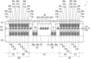
- FIGS. 3 A and 3 B are plan views illustrating a guard ring of the semiconductor device that is an example of the semiconductor device of the first embodiment to which the present technology is applied.
- FIGS. 4 A to 4 C are (first) explanatory diagrams illustrating an example of a manufacturing method of a semiconductor device of a second embodiment to which the present technology is applied.
- FIGS. 5 A to 5 C are (second) explanatory diagrams illustrating an example of the manufacturing method of the semiconductor device of the second embodiment to which the present technology is applied.
- FIGS. 6 A and 6 B are (third) explanatory diagrams illustrating an example of the manufacturing method of the semiconductor device of the second embodiment to which the present technology is applied.
- FIGS. 7 A and 7 B are (fourth) explanatory diagrams illustrating an example of the manufacturing method of the semiconductor device of the second embodiment to which the present technology is applied.
- FIGS. 8 A and 8 B are (fifth) explanatory diagrams illustrating an example of the manufacturing method of the semiconductor device of the second embodiment to which the present technology is applied.
- FIGS. 9 A and 9 B are (sixth) explanatory diagrams illustrating an example of the manufacturing method of the semiconductor device of the second embodiment to which the present technology is applied.
- FIGS. 10 A and 10 B are (seventh) explanatory diagrams illustrating an example of the manufacturing method of the semiconductor device of the second embodiment to which the present technology is applied.
- FIGS. 11 A and 11 B are (eighth) explanatory diagrams illustrating an example of the manufacturing method of the semiconductor device of the second embodiment to which the present technology is applied.
- FIGS. 12 A and 12 B are (ninth) explanatory diagrams illustrating an example of the manufacturing method of the semiconductor device of the second embodiment to which the present technology is applied.
- FIGS. 13 A and 13 B are (tenth) explanatory diagrams illustrating an example of the manufacturing method of the semiconductor device of the second embodiment to which the present technology is applied.
- FIGS. 14 A and 14 B are (first) explanatory diagrams illustrating a case where a third guard ring is not conductively connected to a power source pad, in a semiconductor device manufactured by the manufacturing method of the semiconductor device of the second embodiment.
- FIGS. 15 A and 15 B are (second) explanatory diagrams illustrating a case where the third guard ring is not conductively connected to the power source pad, in the semiconductor device manufactured by the manufacturing method of the semiconductor device of the second embodiment.
- FIGS. 16 A and 16 B are (first) explanatory diagrams illustrating a semiconductor device that is an example of a semiconductor device of a third embodiment according to the present technology.
- FIGS. 17 A and 17 B are (second) explanatory diagrams illustrating the semiconductor device that is an example of the semiconductor device of the third embodiment according to the present technology.
- FIGS. 18 A and 18 B are (third) explanatory diagrams illustrating the semiconductor device that is an example of the semiconductor device of the third embodiment according to the present technology.
- FIGS. 19 A and 19 B are (fourth) explanatory diagrams illustrating the semiconductor device that is an example of the semiconductor device of the third embodiment according to the present technology.
- FIGS. 20 A and 20 B are (first) explanatory diagrams illustrating a semiconductor device that is an example of a semiconductor device of a fourth embodiment according to the present technology.
- FIGS. 21 A and 21 B are (second) explanatory diagrams illustrating the semiconductor device that is an example of the semiconductor device of the fourth embodiment according to the present technology.
- FIGS. 22 A and 22 B are (first) explanatory diagrams illustrating a semiconductor device that is an example of a semiconductor device of a fifth embodiment according to the present technology.
- FIGS. 23 A and 23 B are (second) explanatory diagrams illustrating the semiconductor device that is an example of the semiconductor device of the fifth embodiment according to the present technology.
- FIGS. 24 A and 24 B are (first) explanatory diagrams illustrating a semiconductor device that is an example of a semiconductor device of a sixth embodiment according to the present technology.
- FIGS. 25 A and 25 B are (second) explanatory diagrams illustrating the semiconductor device that is an example of the semiconductor device of the sixth embodiment according to the present technology.
- FIGS. 26 A and 26 B are (first) explanatory diagrams illustrating an example of a manufacturing method of a semiconductor device of a seventh embodiment to which the present technology is applied.
- FIGS. 27 A and 27 B are (second) explanatory diagrams illustrating an example of the manufacturing method of the semiconductor device of the seventh embodiment to which the present technology is applied.
- FIGS. 28 A and 28 B are (third) explanatory diagrams illustrating an example of the manufacturing method of the semiconductor device of the seventh embodiment to which the present technology is applied.
- FIGS. 29 A and 29 B are (fourth) explanatory diagrams illustrating an example of the manufacturing method of the semiconductor device of the seventh embodiment to which the present technology is applied.
- FIGS. 30 A and 30 B are (fifth) explanatory diagrams illustrating an example of the manufacturing method of the semiconductor device of the seventh embodiment to which the present technology is applied.
- FIGS. 31 A and 31 B are (sixth) explanatory diagrams illustrating an example of the manufacturing method of the semiconductor device of the seventh embodiment to which the present technology is applied.
- FIGS. 32 A and 32 B are (seventh) explanatory diagrams illustrating an example of the manufacturing method of the semiconductor device of the seventh embodiment to which the present technology is applied.
- FIGS. 33 A and 33 B are (eighth) explanatory diagrams illustrating an example of the manufacturing method of the semiconductor device of the seventh embodiment to which the present technology is applied.
- FIGS. 34 A and 34 B are (ninth) explanatory diagrams illustrating an example of the manufacturing method of the semiconductor device of the seventh embodiment to which the present technology is applied.
- FIGS. 35 A and 35 B are (tenth) explanatory diagrams illustrating an example of the manufacturing method of the semiconductor device of the seventh embodiment to which the present technology is applied.
- FIGS. 36 A and 36 B are (eleventh) explanatory diagrams illustrating an example of the manufacturing method of the semiconductor device of the seventh embodiment to which the present technology is applied.
- FIGS. 37 A and 37 B are (twelfth) explanatory diagrams illustrating an example of the manufacturing method of the semiconductor device of the seventh embodiment to which the present technology is applied.
- FIGS. 38 A and 38 B are (thirteenth) explanatory diagrams illustrating an example of the manufacturing method of the semiconductor device of the seventh embodiment to which the present technology is applied.
- FIGS. 39 A and 39 B are (first) explanatory diagrams illustrating a case where a third guard ring is not conductively connected to a power source pad, in a semiconductor device manufactured by the manufacturing method of the semiconductor device of the seventh embodiment.
- FIGS. 40 A and 40 B are (second) explanatory diagrams illustrating a case where the third guard ring is not conductively connected to the power source pad, in the semiconductor device manufactured by the manufacturing method of the semiconductor device of the seventh embodiment.
- FIGS. 41 A and 41 B are (first) explanatory diagrams illustrating a semiconductor device that is an example of a semiconductor device of an eighth embodiment according to the present technology.
- FIGS. 42 A and 42 B are (second) explanatory diagrams illustrating the semiconductor device that is an example of the semiconductor device of the eighth embodiment according to the present technology.
- FIGS. 43 A and 43 B are (third) explanatory diagrams illustrating the semiconductor device that is an example of the semiconductor device of the eighth embodiment according to the present technology.
- FIGS. 44 A and 44 B are (fourth) explanatory diagrams illustrating the semiconductor device that is an example of the semiconductor device of the eighth embodiment according to the present technology.
- FIGS. 45 A and 45 B are (fifth) explanatory diagrams illustrating the semiconductor device that is an example of the semiconductor device of the eighth embodiment according to the present technology.
- FIGS. 46 A and 46 B are (sixth) explanatory diagrams illustrating the semiconductor device that is an example of the semiconductor device of the eighth embodiment according to the present technology.
- FIG. 47 is an explanatory diagram illustrating a semiconductor device that is an example of a semiconductor device of a ninth embodiment according to the present technology.
- FIGS. 48 A and 48 B are explanatory diagrams illustrating an arrangement example of a third guard ring of the semiconductor device that is an example of the semiconductor device of the ninth embodiment according to the present technology.
- FIGS. 49 A and 49 B are explanatory diagrams illustrating the semiconductor device that is an example of the semiconductor device of the ninth embodiment according to the present technology.
- FIGS. 50 A and 50 B are explanatory diagrams illustrating a state in which a semiconductor device is cut by a dicing blade.
- FIGS. 51 A and 51 B are explanatory diagrams illustrating a state of a case where a Cu dummy of the third guard ring stops an inner crack, in the semiconductor device of the ninth embodiment of the present technology.
- FIGS. 52 A and 52 B are explanatory diagrams illustrating the semiconductor device in which the third guard ring is formed in both of a sealing region and a crack stopper region, in the semiconductor device of the ninth embodiment.
- FIGS. 53 A and 53 B are explanatory diagrams illustrating an example where the inner crack obliquely enters the third guard ring, and an example where the shape of the third guard ring is changed, in the semiconductor device of the ninth embodiment.
- FIGS. 54 A and 54 B are (first) diagrams of a semiconductor device illustrating an example of a semiconductor device of a tenth embodiment according to the present technology.
- FIGS. 55 A and 55 B are (second) diagrams of the semiconductor device illustrating an example of the semiconductor device of the tenth embodiment according to the present technology.
- FIG. 56 is a diagram illustrating a usage example of a solid-state imaging device of the first embodiment to the tenth embodiment to which the present technology is applied.
- FIG. 57 is a functional block diagram of an example of an electronic device to which the present technology is applied.
- FIG. 58 is a diagram illustrating an example of a schematic configuration of an endoscopic surgery system.
- FIG. 59 is a block diagram illustrating an example of a functional configuration of a camera head and a CCU.
- FIG. 60 is a block diagram illustrating an example of a schematic configuration of a vehicle control system.
- FIG. 61 is an explanatory diagram illustrating an example of an installation position of a vehicle exterior information detection unit and an imaging unit.
- FIGS. 62 A and 62 B are explanatory diagrams illustrating a state in which an inner crack occurs at the time of dicing a semiconductor device by a dicing blade.
- FIG. 63 is an explanatory diagram illustrating a state in which chipping occurs by machining a semiconductor device with a dicing blade.
- FIG. 64 is a block diagram illustrating a configuration of a CMOS image sensor on which a column parallel ADC according to the present technology is mounted.
- FIG. 65 is a sectional view illustrating a configuration example of a solid-state imaging device to which a technology according to the present disclosure can be applied.
- the present technology relates to dicing of a semiconductor device or examination of a semiconductor device, in a semiconductor device in which two semiconductor substrates are laminated. According to the present technology, it is possible to improve the quality of the semiconductor device.
- the inner crack and the chipping occur at the time of the dicing, or the moisture infiltrates into the chip from the end portion of the chip after opening, and thus, there is a concern that the reliability of the semiconductor device decreases.
- FIGS. 62 A and 62 B a state is illustrated in which the inner crack occurs at the time of dicing the semiconductor device by a dicing blade.
- FIG. 62 A illustrates a sectional view of a semiconductor device 700
- FIG. 62 B illustrates a plan view of a junction interface IF of the semiconductor device.
- up indicates an upper direction in FIGS. 62 A and 62 B
- right indicates a right direction in FIGS. 62 A and 62 B .
- the semiconductor device 700 includes a first semiconductor substrate 800 and a second semiconductor substrate 900 .
- the first semiconductor substrate 800 includes a sealing region SR and a crack stopper region CS outside a chip region CA (that is, a dicing blade DB side).
- the first semiconductor substrate 800 includes a first guard ring 11 a and a first guard ring 11 b in the crack stopper region CS, and includes a first guard ring 11 c and a first guard ring 11 d in the sealing region SR.
- a guard ring may also be referred to as a guard element.
- the second semiconductor substrate 900 includes the sealing region SR and the crack stopper region CS outside the chip region CA (that is, the dicing blade DB side).
- the second semiconductor substrate 900 includes a second guard ring 21 a and a second guard ring 21 b in the crack stopper region CS, and includes a second guard ring 21 c and a second guard ring 21 d in the sealing region SR.
- a first copper (Cu) dummy (hereinafter, referred to as a Cu dummy) DP 11 is formed inside the chip region CA, and is formed on a first junction surface FS of the first semiconductor substrate 800 and a second junction surface SS of the second semiconductor substrate 900 .
- the first Cu dummy DP 11 is provided to increase a junction strength between the first semiconductor substrate 800 and the second semiconductor substrate 900 .
- the semiconductor device 700 is machined by the dicing blade DB in a dicing area DA, and is divided into two parts.
- An inner crack ICD 1 and an inner crack ICD 2 represent that a chap or a cleavage occurs on the first semiconductor substrate 800 and the second semiconductor substrate 900 at the time of the dicing. Furthermore, the inner crack ICD 1 represents a chap formed on the first junction surface FS of the first semiconductor substrate 800 and the second junction surface SS of the second semiconductor substrate 900 .
- the inner crack ICD 1 reaches the inside of the first semiconductor substrate 800 and the second semiconductor substrate 900 , and thus, disconnection occurs in the wiring of a copper (Cu)-copper (Cu) junction (hereinafter, referred to as a Cu—Cu junction), or the moisture infiltrates from the Cu—Cu junction surface, and therefore, the wiring can be corroded in the chip region CA.
- a Cu—Cu junction copper-copper (Cu) junction
- FIG. 63 illustrates a state after dicing in which chipping occurs in the semiconductor device 700 .
- FIG. 63 is an explanatory diagram illustrating a state where chipping occurs by machining the semiconductor device 700 with the dicing blade DB.
- the impact of the inner crack ICD 1 is propagated into the chip through the first Cu dummy DP 11 , and chipping occurs.
- the second guard ring 21 a , the second guard ring 21 b , the second guard ring 21 c , and the second guard ring 21 d are a guard ring formed on the second semiconductor substrate 900 .
- the semiconductor device 700 a in the semiconductor device 700 a , the impact reaches the chip region of the semiconductor device 700 a due to the chipping, and thus, the semiconductor device 700 a is determined as a product defect. In a case where the semiconductor device 700 a is determined as the product defect, there is a possibility that a yield ratio decreases, and the reliability is impaired.
- the present technology has been made in consideration of the circumstances described above, and is capable of improving the reliability of the quality of the semiconductor device, on the junction surface of the Cu—Cu junction. With this arrangement, the present technology is capable of improving the yield ratio of the semiconductor device, and of improving the reliability.
- FIG. 64 and FIG. 65 an overall configuration example of a solid-state imaging device will be described as an example semiconductor device according to an embodiment of the present technology, by using FIG. 64 and FIG. 65 .
- FIG. 64 is a block diagram illustrating the overall configuration of a solid-state imaging device according to an embodiment of the present technology, for example, a CMOS image sensor on which a column parallel ADC is mounted.
- a CMOS image sensor q 10 includes a row scanning circuit q 13 , a column processing unit q 14 , a reference voltage supply unit q 15 , a column scanning circuit q 16 , a horizontal output line q 17 , and a timing control circuit q 18 , in addition to a pixel array portion q 12 in which a plurality of unit pixels q 11 including a photoelectric conversion element are two-dimensionally arranged into the shape of a matrix.
- the timing control circuit q 18 generates a clock signal, a control signal, or the like that is a reference for the operation of the row scanning circuit q 13 , the column processing unit q 14 , the reference voltage supply unit q 15 , the column scanning circuit q 16 , and the like, on the basis of a master clock MCK, and applies the clock signal, the control signal, or the like to the row scanning circuit q 13 , the column processing unit q 14 , the reference voltage supply unit q 15 , the column scanning circuit q 16 , and the like.
- a peripheral driving system or signal processing system for driving and controlling each of the unit pixels q 11 of the pixel array portion q 12 that is, the row scanning circuit q 13 , the column processing unit q 14 , the reference voltage supply unit q 15 , the column scanning circuit q 16 , the horizontal output line q 17 , the timing control circuit q 18 , and the like are integrated on a chip (a semiconductor substrate) q 19 that is the same as the pixel array portion q 12 .
- a unit pixel having a three-transistor configuration including a transfer transistor transferring charge obtained by performing photoelectric conversion with the photoelectric conversion element to a floating diffusion (FD) unit, a reset transistor controlling the potential of the FD unit, and an amplification transistor outputting a signal according to the potential of the FD unit
- a unit pixel having a four-transistor configuration further including a selection transistor for performing pixel selection in addition to the three-transistor configuration, or the like can be used as the unit pixel q 11 , in addition to the photoelectric conversion element (for example, a photodiode).
- the unit pixels q 11 of m-column n-row are two-dimensionally arranged, and in pixel arrangement of m-row n-column, a row control line q 21 (q 21 - 1 to q 21 - n ) is wired for each row, and a column signal line q 22 (q 22 - 1 to q 22 - m ) is wired for each column.
- Each one end of the row control lines q 21 - 1 to q 21 - n is connected to each output end corresponding to each row of the row scanning circuit q 13 .
- the row scanning circuit q 13 includes a shift register or the like, and controls a row address or row scanning of the pixel array portion q 12 through the row control lines q 21 - 1 to q 21 - n.
- the column processing unit q 14 includes analog-digital conversion circuits (ADCs) q 23 - 1 to q 23 - m provided for each pixel column of the pixel array portion q 12 , that is, for each of the column signal lines q 22 - 1 to q 22 - m , converts an analog signal that is output for each column from each of the unit pixels q 11 of the pixel array portion q 12 , into a digital signal, and outputs the digital signal. Furthermore, the details of the configuration of the ADCs q 23 - 1 to q 23 - m will be described later.
- ADCs analog-digital conversion circuits
- the reference voltage supply unit q 15 for example, includes a digital-analog conversion circuit (DAC) q 151 as a unit generating a reference voltage Vref of a so-called ramp (RAMP) waveform, of which the level is obliquely changed as time elapses. Furthermore, the unit generating the reference voltage Vref of the ramp waveform is not limited to the DAC q 151 .
- DAC digital-analog conversion circuit
- the DAC q 151 generates the reference voltage Vref of the ramp waveform on the basis of a clock CK applied from the timing control circuit q 18 , and supplies the reference voltage Vref to the ADCs q 23 - 1 to q 23 - m of the column processing unit q 15 , under the control of a control signal CS 1 applied from the timing control circuit q 18 .
- Each of the ADCs q 23 - 1 to q 23 - m is capable of selectively performing an AD conversion operation corresponding to each operation mode of a normal frame rate mode, and a high frame rate mode in which an exposure time of the unit pixel q 11 is set to 1/N, and thus, a frame rate is set to N times, for example, 2 times, compared to the normal frame rate mode in a progressive scanning method of reading out information of all of the unit pixels q 11 .
- the operation mode is switched according to the control of control signals CS 2 and CS 3 applied from the timing control circuit q 18 .
- instruction information for switching each of the operation modes of the normal frame rate mode and the high frame rate mode is applied to the timing control circuit q 18 from an external system controller (not illustrated).
- the ADC 23 - m includes a comparator q 31 , for example, an up/down counter (in the drawing, represented as U/DCNT) q 32 that is a counter, a transfer switch q 33 , and a memory device q 34 .
- a comparator q 31 for example, an up/down counter (in the drawing, represented as U/DCNT) q 32 that is a counter, a transfer switch q 33 , and a memory device q 34 .
- the comparator q 31 compares a signal voltage Vx of the column signal line 22 - m according to the signal output from each of the unit pixels q 11 of the n-th column of the pixel array portion q 12 , with the reference voltage Vref of the ramp waveform supplied from the reference voltage supply unit q 15 , and for example, when the reference voltage Vref is greater than the signal voltage Vx, an output Vco becomes an “H” level, and when the reference voltage Vref is less than or equal to the signal voltage Vx, the output Vco becomes an “L” level.
- the up/down counter q 32 is an asynchronous counter, and under the control of the control signal CS 2 applied from the timing control circuit q 18 , the clock CK is applied from the timing control circuit q 18 , along with the DAC q 151 , and down (DOWN) count or up (UP) count is performed in synchronization with the clock CK, and thus, a comparison period from the start of a comparison operation to the end of the comparison operation in the comparator q 31 is measured.
- the down count is performed at the time of the first read-out operation, and thus, a comparison time at the time of the first read-out is measured, and the up count is performed at the time of the second read-out operation, and thus, a comparison time at the time of the second read-out is measured.
- a count result with respect to the unit pixel q 11 of a certain row is retained as it is, and subsequently, from the previous count result, the down count is performed with respect to the unit pixel q 11 of the next row at the time of the first read-out operation and thus, the comparison time at the time of first read-out is measured, and the up count is performed with respect to the unit pixel q 11 of the next row at the time of the second read-out operation, and thus, the comparison time at the time of the second read-out is measured.
- the transfer switch q 33 is in an on (closed) state at a time point when a count operation of the up/down counter q 32 with respect to the unit pixel q 11 of a certain row is completed, and transfers the count result of the up/down counter q 32 to the memory device q 34 , under the control of the control signal CS 3 applied from the timing control circuit q 18 .
- the transfer switch q 33 is in an off (opened) state at a time point when the count operation of the up/down counter q 32 with respect to the unit pixel q 11 of a certain row is completed, and subsequently, is in the on state at a time point when the count operation of the up/down counter q 32 with respect to the unit pixel q 11 of the next row is completed, and transfers the count result of two vertical pixels of the up/down counter q 32 to the memory device q 34 .
- the analog signal that is supplied to each column from each of the unit pixels q 11 of the pixel array portion q 12 through the column signal lines q 22 - 1 to q 22 - m is converted to the digital signal of N bits according to each operation of the comparator q 31 and the up/down counter q 32 of the ADC q 23 (q 23 - 1 to q 23 - m ), and is stored in the memory device q 34 (q 34 - 1 to q 34 - m ).
- the column scanning circuit q 16 includes the shift register or the like, and controls the column address or the column scanning of the ADCs q 23 - 1 to q 23 - m of the column processing unit q 14 .
- the digital signals of N bits subjected to the AD conversion in each of the ADCs q 23 - 1 to q 23 - m are sequentially read out to the horizontal output line q 17 , and are output as imaging data through the horizontal output line q 17 , under the control of the column scanning circuit q 16 .
- a circuit or the like performing various signal processings with respect to the imaging data output through the horizontal output line q 17 , can also be provided in addition to the constituents described above.
- the count result of the up/down counter q 32 can be selectively transferred to the memory device q 34 through the transfer switch q 33 , and thus, the count operation of the up/down counter q 32 , and the read-out operation of the count result of the up/down counter q 32 with respect to the horizontal output line q 17 , can be independently controlled.
- each circuit may be provided in either of the first semiconductor substrate 800 and the second semiconductor substrate 900 illustrated in FIGS. 62 A and 62 B .
- a part of a circuit illustrated in FIG. 64 may not be provided in the semiconductor device 700 .
- FIG. 65 is a sectional view illustrating the overall configuration example of the solid-state imaging device to which the present technology can be applied.
- a photodiode (PD) 20019 receives incident light 20001 that is incident from a rear surface (in FIG. 65 , an upper surface) side of a semiconductor substrate 20018 .
- a flattening film 20013 , a color filter (CF) 20012 , and a microlens 20011 are provided above the PD 20019 , and the incident light 20001 that is sequentially incident through each unit, is received on a receiving surface 20017 , and is subjected to photoelectric conversion.
- the semiconductor substrate 20018 for example, corresponds to a first semiconductor substrate 10 illustrated in FIG. 1 , as described later.
- the PD 20019 is formed as a charge accumulation region for an n type semiconductor region 20020 to accumulate charges (electrons).
- the n type semiconductor region 20020 is provided in p type semiconductor regions 20016 and 20041 of the semiconductor substrate 20018 .
- the PD 20019 has a hole-accumulation diode (HAD) structure, and the p type semiconductor regions 20016 and 20041 are formed on each interface between the upper surface side and the lower surface side of the n type semiconductor region 20020 , in order to prevent a dark current from being generated or to reduce the dark current.
- HAD hole-accumulation diode
- a pixel separation portion 20030 electrically separating a plurality of pixels 20010 is provided, and the PD 20019 is provided in a region partitioned by the pixel separation portion 20030 .
- the pixel separation portion 20030 in a case where the solid-state imaging device is seen from the upper surface side, the pixel separation portion 20030 , for example, is formed into the shape of a grid through the plurality of pixels 20010 , and the PD 20019 is formed in the region partitioned by the pixel separation portion 20030 .
- each PD 20019 an anode is grounded, and in the solid-state imaging device, signal charges (for example, electrons) accumulated by the PD 20019 , are read out through a transfer Tr (MOS FET) (not illustrated) or the like, and are output to a vertical signal line (VSL) (not illustrated) as an electric signal.
- MOS FET transfer Tr
- VSL vertical signal line
- a wiring layer 20050 is provided on the front surface (the lower surface) of the semiconductor substrate 20018 , on a side opposite to the rear surface (the upper surface) on which each unit such as a light shielding film 20014 , the CF 20012 , and the microlens 20011 is provided.
- the wiring layer 20050 includes wiring 20051 and an insulating layer 20052 , and in the insulating layer 20052 , the wiring 20051 is formed to be electrically connected to each element.
- the wiring layer 20050 is a so-called multilayer wiring layer, and is formed by alternately laminating an interlayer insulating film configuring the insulating layer 20052 and the wiring 20051 a plurality of times.
- wiring with respect to a Tr for reading out the charges from the PD 20019 such as the transfer Tr
- wiring for reading out the charges, such as the VSL are laminated through the insulating layer 20052 , as the wiring 20051 .
- a support substrate 20061 is provided on the wiring layer 20050 on a side opposite to a side where the PD 20019 is provided.
- a substrate including a silicon semiconductor, of which the thickness is several hundred mm, is provided as the support substrate 20061 .
- the light shielding film 20014 is provided on the rear surface (in FIG. 65 , the upper surface) side of the semiconductor substrate 20018 .
- the light shielding film 20014 shields a part of the incident light 20001 that is directed towards the rear surface of the semiconductor substrate 20018 from the upper portion of the semiconductor substrate 20018 .
- the light shielding film 20014 is provided in the upper portion of the pixel separation portion 20030 that is provided in the semiconductor substrate 20018 .
- the light shielding film 20014 is provided on the rear surface (the upper surface) of the semiconductor substrate 20018 to protrude into a convex shape through the insulating film 20015 such as a silicon oxide film.
- the light shielding film 20014 is not provided in the upper portion of the PD 20019 provided in the semiconductor substrate 20018 , but the upper portion of the PD 20019 is opened such that the incident light 20001 is incident on the PD 20019 .
- the planar shape of the light shielding film 20014 is in the shape of a grid, and an opening through which the incident light 20001 passes to the receiving surface 20017 , is formed.
- the light shielding film 20014 contains a light shield material that shields light.
- a titanium (Ti) film and a tungsten (W) film are sequentially laminated, and thus, the light shielding film 20014 is formed.
- the light shielding film 20014 for example, can be formed by sequentially laminating a titanium nitride (TiN) film and a tungsten (W) film.
- the light shielding film 20014 is covered with the flattening film 20013 .
- the flattening film 20013 is formed by using an insulating material that transmits light.
- the pixel separation portion 20030 includes a groove 20031 , a fixed charge film 20032 , and an insulating film 20033 .
- the fixed charge film 20032 is formed to cover the groove 20031 that partitions the plurality of pixels 20010 , on the rear surface (the upper surface) side of the semiconductor substrate 20018 .
- the fixed charge film 20032 is provided to cover an inner surface of the groove 20031 formed on the rear surface (the upper surface) side in the semiconductor substrate 20018 , with a constant thickness. Then, the insulating film 20033 is provided to bury (fill) the inside of the groove 20031 covered with the fixed charge film 20032 .
- the fixed charge film 20032 is formed by using a high dielectric body having a negative fixed charge such that a positive charge (hole) accumulation region is formed in an interface portion with respect to the semiconductor substrate 20018 , and a dark current is prevented from being generated or reduced.
- the fixed charge film 20032 is formed to have the negative fixed charge, and thus, an electric field is added to the interface with respect to the semiconductor substrate 20018 according to the negative fixed charge, and the positive charge (hole) accumulation region is formed.
- the fixed charge film 20032 is capable of including a hafnium oxide film (a HfO 2 film).
- the fixed charge film 20032 for example, is capable of containing at least one of oxides of hafnium, zirconium, aluminum, tantalum, titanium, magnesium, yttrium, a lanthanoid element, and the like.
- the technology according to the present disclosure can also be applied to the solid-state imaging device as described above.
- a semiconductor device of a first embodiment according to the present technology is a semiconductor device, including: a first semiconductor substrate; a second semiconductor substrate; and at least one guard ring unit including a first guard ring, a second guard ring, and a third guard ring, in which the first semiconductor substrate and the second semiconductor substrate are joined together by a first junction surface of the first semiconductor substrate and a second junction surface of the second semiconductor substrate, the first guard ring is formed on the first semiconductor substrate, the second guard ring is formed on the second semiconductor substrate, and the third guard ring is formed on the first junction surface and the second junction surface.
- a solid-state imaging device of the first embodiment of the present technology it is possible to improve the reliability of the quality of the semiconductor device, on the junction surface of the Cu—Cu junction.
- FIG. 1 to FIG. 3 B illustrate a semiconductor device 1 that is an example of the semiconductor device of the first embodiment according to the present technology.
- FIG. 1 illustrates the sectional view of the semiconductor device 1 .
- FIG. 2 illustrates the top view of the semiconductor device before machining the semiconductor device 1 .
- FIGS. 3 A and 3 B illustrate partially enlarged views in which the semiconductor device and a region Q of the semiconductor device before machining the semiconductor device 1 , are partially enlarged.
- FIG. 1 illustrates a sectional surface cut along A-A′ of FIG. 2 .
- FIG. 2 illustrates a semiconductor device including four semiconductor devices of a semiconductor device 1 a , a semiconductor device 1 b , a semiconductor device 1 c , and a semiconductor device 1 d , in a state before dicing the semiconductor device 1 .
- the semiconductor device 1 illustrated in FIG. 1 is formed by dicing the dicing area DA illustrated in FIG. 2 with the dicing blade DB.
- the sealing region SR and the crack stopper region CS of the semiconductor device 1 a are formed to surround at least a part of the circumference of the semiconductor device 1 a.
- FIG. 3 A illustrates a state before dicing the semiconductor device 1
- FIG. 3 B illustrates a partially enlarged view in which the plan view of the crack stopper region CS and the sealing region SR in the region Q of the semiconductor device 1 a is partially enlarged.
- the semiconductor device 1 a includes a pixel region 50 , a power source pad 40 a , a power source pad 40 b , a power source pad 40 c , a power source pad 40 d , a power source pad 40 e , a power source pad 40 f , a power source pad 41 a , a power source pad 41 b , a power source pad 41 c , a power source pad 41 d , a power source pad 41 e , a power source pad 41 f , the sealing region SR, and the crack stopper region CS.
- guard ring units As illustrated in FIG. 3 B , three guard ring units (a guard ring unit GU 1 , a guard ring unit GU 2 , and a guard ring unit GU 3 ) are formed in the crack stopper region CS.
- Four guard ring units (a guard ring unit GU 4 , a guard ring unit GU 5 , a guard ring unit GU 6 , and a guard ring unit GU 7 ) are formed in the sealing region SR.
- a guard ring unit may also be referred to as a guard ring structure, guard structure, or the like.
- the semiconductor device 1 illustrated in FIG. 1 includes the first semiconductor substrate 10 , the second semiconductor substrate 20 , and at least one guard ring unit 30 a including the first guard ring 11 a , the second guard ring 21 a , and a third guard ring 31 a .
- the first semiconductor substrate 10 and the second semiconductor substrate 20 are joined together by the first junction surface FS of the first semiconductor substrate 10 and the second junction surface SS of the second semiconductor substrate 20 , the first guard ring 11 a is formed on the first semiconductor substrate 10 , the second guard ring 21 a is formed on the second semiconductor substrate 20 , and the third guard ring 31 a is formed on the first junction surface FS and the second junction surface SS.
- the first semiconductor substrate 10 and the second semiconductor substrate 20 include the sealing region SR and the crack stopper region CS outside the chip region CA (that is, outside the pixel region 50 ).
- the first guard ring 11 a , the first guard ring 11 b , and the first guard ring 11 c are formed in the crack stopper region CS on the first semiconductor substrate 10 .
- the first guard ring 11 d , a first guard ring 11 e , a first guard ring 11 f , and a first guard ring 11 g are formed in the sealing region SR on the first semiconductor substrate 10 .
- the first guard rings will be collectively referred to as a first guard ring 11 .
- the second guard ring 21 a , the second guard ring 21 b , and the second guard ring 21 c are formed in the crack stopper region CS on the second semiconductor substrate 20 .
- the second guard ring 21 d , a second guard ring 21 e , a second guard ring 21 f , and a second guard ring 21 g are formed in the sealing region SR on the second semiconductor substrate 20 .
- the second guard rings will be collectively referred to as a second guard ring 21 .
- the third guard ring 31 a , a third guard ring 31 b , a third guard ring 31 c , a third guard ring 31 d , a third guard ring 31 e , a third guard ring 31 f , and a third guard ring 31 g are formed on the first junction surface FS and the second junction surface SS. Furthermore, in a case where it is not necessary to specify any one of the third guard rings 31 , the third guard rings 31 will be collectively referred to as a third guard ring 31 .
- the guard ring unit 30 a includes the first guard ring 11 a , the second guard ring 21 a , and the third guard ring 31 a .
- a guard ring unit 30 b includes the first guard ring 11 b , the second guard ring 21 b , and the third guard ring 31 b .
- a guard ring unit 30 c includes the first guard ring 11 c , the second guard ring 21 c , and the third guard ring 31 c .
- a guard ring unit 30 d includes the first guard ring 11 d , the second guard ring 21 d , and the third guard ring 31 d .
- a guard ring unit 30 e includes the first guard ring 11 e , the second guard ring 21 e , and the third guard ring 31 e .
- a guard ring unit 30 f includes the first guard ring 11 f , the second guard ring 21 f , and the third guard ring 31 f .
- a guard ring unit 30 g includes the first guard ring 11 g , the second guard ring 21 g , and the third guard ring 31 g.
- the guard ring units will be collectively referred to as a guard ring unit 30 .
- guard ring unit 30 is formed in a guard ring region GR.
- guard ring region GR includes the sealing region SR and the crack stopper region CS.
- a first Cu dummy DP 1 , a first Cu dummy DP 2 , and a first Cu dummy DP 3 are formed on the first junction surface FS of the first semiconductor substrate 10 and the second junction surface SS of the second semiconductor substrate 20 .
- the first Cu dummy DP 1 , the first Cu dummy DP 2 , and the first Cu dummy DP 3 are a connection pad dummy provided for increasing a junction strength between the first semiconductor substrate 10 and the second semiconductor substrate 20 .
- the terms “Cu dummy,” “dummy structure,” and the like may refer to conductive pad and/or wiring that does not carry an electrical signal (e.g., such as a pixel signal or a power supply signal).
- the semiconductor device 1 is formed by pasting the first semiconductor substrate 10 and the second semiconductor substrate 20 to each other.
- the semiconductor device 1 for example, the first junction surface FS of the first semiconductor substrate 10 and the second junction surface SS of the second semiconductor substrate 20 are joined together according to a plasma junction.
- the first semiconductor substrate 10 includes the pixel region 50 including a plurality of pixels.
- the pixel region 50 for example, is formed by including a plurality of photodiodes forming unit pixels.
- the second semiconductor substrate 20 includes a power source pad 40 , a power source pad 41 , and a wiring layer 62 , and a part of a logic circuit is formed.
- the wiring layer 62 includes wiring 60 a , wiring 60 b , and an insulating film 61 .
- a plurality of wiring layers 62 and the interlayer insulating film therebetween form a multilayer wiring layer.
- the semiconductor device 1 illustrated in FIG. 1 represents a configuration example of a laminated solid-state imaging device formed by pasting two semiconductor substrates (the first semiconductor substrate 10 and the second semiconductor substrate 20 ) to each other.
- the upper side of FIG. 1 is a receiving surface side on which light is incident, and is a rear surface side of the first semiconductor substrate 10
- the semiconductor device 1 is a rear surface irradiation type solid-state imaging device.
- the rear surface irradiation type solid-state imaging device is an example of the semiconductor device 1 , but is not limited thereto.
- the semiconductor device 1 of the first embodiment according to the present technology includes the at least one guard ring unit 30 including the first guard ring 11 , the second guard ring 21 , and the third guard ring 31 .
- the first semiconductor substrate 10 and the second semiconductor substrate 20 are joined together by the first junction surface FS of the first semiconductor substrate 10 and the second junction surface SS of the second semiconductor substrate 20 , and the third guard ring 31 is formed on the first junction surface FS and the second junction surface SS.
- the guard ring unit 30 includes the third guard ring 31 on the junction interface IF formed by joining the first semiconductor substrate 10 and the second semiconductor substrate 20 together, and thus, it is possible to prevent or reduce the infiltration of the moisture from the outside.
- the semiconductor device 1 of the first embodiment according to the present technology is capable of improving the reliability of the quality of the semiconductor device, on the junction surface of the Cu—Cu junction.
- a manufacturing method of a semiconductor device of a second embodiment according to the present technology is a manufacturing method of a semiconductor device, including: joining the first semiconductor substrate and the second semiconductor substrate together to face each other; forming the third guard ring on the first junction surface of the first semiconductor substrate and the second junction surface of the second semiconductor substrate; and forming the guard ring unit 30 by the first guard ring 11 , the second guard ring 21 , and the third guard ring 31 .
- FIG. 4 A to FIG. 13 B illustrate an example of a manufacturing method of the semiconductor device 1 of the second embodiment according to the present technology. Furthermore, unless otherwise particularly noted, “up” indicates an upper direction in FIG. 4 A to FIG. 13 B , and “down” indicates a lower direction in FIG. 4 A to FIG. 13 B .
- a in each of the drawings illustrates a sectional view, and B in each of the drawings, illustrates a plan view.
- FIGS. 4 A to 4 C illustrate the first semiconductor substrate 10
- FIGS. 5 A to 5 C illustrate the second semiconductor substrate 20
- the first semiconductor substrate 10 and the second semiconductor substrate 20 for example, contain single crystalline silicon.
- An oxide film is formed on the front surface of each of the first semiconductor substrate 10 and the second semiconductor substrate 20 , and a plurality of wiring layers are provided on the underlayer.
- the first semiconductor substrate 10 illustrated in FIGS. 4 A to 4 C includes the first guard ring 11 a , the first guard ring 11 b , the first guard ring 11 c , the wiring 60 a , the wiring 60 b , an insulating film 61 a , a wiring layer 62 a , and an interlayer insulating film 71 .
- An electrode pad EP 1 is provided in the first guard ring 11 a .
- An electrode pad EP 2 is provided in the first guard ring 11 b .
- An electrode pad EP 3 is provided in the first guard ring 11 c.
- the first guard ring 11 a , the first guard ring 11 b , and the first guard ring 11 c are not used as wiring, but are dummy wiring for preventing or reducing the infiltration of the moisture.
- the first guard ring 11 a , the first guard ring 11 b , and the first guard ring 11 c for example, four layers of dummy wirings are superimposed.
- the first guard ring 11 a , the first guard ring 11 b , and the first guard ring 11 c are connected to each other by wiring in which a via layer is formed between the dummy wirings of each of the layers, or the like, and the dummy wiring of the uppermost layer to the dummy wiring of the lowermost layer are continuous.
- FIG. 4 C illustrates the enlarged diagram of a region R 1 of FIG. 4 A .
- the first semiconductor substrate 10 is broadly divided into layers L 1 to L 4 .
- the layer L 1 for example, includes a substrate containing silicon or the like, and a semiconductor element (not illustrated) or the like, such as a transistor or a photodiode, is formed in the substrate.
- a contact CN 1 is mainly formed on the layer L 2 .
- the contact CN 1 electrically connects the semiconductor element formed on the layer L 1 and wiring formed on the layer L 3 , together.
- four dummy wiring layers (a wiring layer WR 1 , a wiring layer WR 2 , a wiring layer WR 3 , and a wiring layer WR 4 ) are formed on the layer L 3 .
- the number of wiring layers can be set to an arbitrary number of greater than or equal to 1.
- the dummy wiring and the via for example, contain copper (Cu), and for example, a barrier metal such as tantalum (Ta) or tantalum nitride (Tan), is formed on the circumference of Cu.
- the electrode pad EP 1 is formed on the layer L 4 .
- the electrode pad EP 1 for example, contains aluminum (Al), and for example, a barrier metal such as titanium (Ti) or tungsten (W), is formed on the circumference of aluminum.
- the first guard ring 11 a includes the contact of the layer L 2 , and the dummy wiring layer of the layer L 3 .
- the interlayer insulating film 71 for insulating each of the layers is formed on the layers L 2 to L 4 .
- the interlayer insulating film 71 for example, contains silicon dioxide (SiO 2 ), silicon nitride (SiN), or the like.
- the second semiconductor substrate 20 illustrated in FIGS. 5 A to 5 C includes the second guard ring 21 a , dummy wiring DW 1 , a dummy pad DPP, dummy wiring DW 2 , the power source pad 40 , the power source pad 41 , the power source pad 41 a , wiring 60 c , wiring 60 d , an insulating film 61 b , a wiring layer 62 b , and the interlayer insulating film 70 .
- the second guard ring 21 a is formed by dummy wiring instead of connection wiring. With this arrangement, the second guard ring 21 a is capable of preventing or reducing an inner crack or chipping.
- FIG. 5 C illustrates the enlarged diagram of the region R 2 of FIG. 5 A .
- the second semiconductor substrate 20 is broadly divided into the layers L 1 to L 4 .
- the layer L 1 for example, includes the substrate containing silicon or the like, and the semiconductor element (not illustrated) or the like, such as a transistor or a photodiode, is formed in the substrate.
- a contact CN 2 is mainly formed on the layer L 2 .
- the contact CN 2 electrically connects the semiconductor element formed on the layer L 1 and the wiring formed on the layer L 3 , together.
- the plurality of wiring layers, and the via layer (including the via) for electrically connecting the wirings together, are formed on the layer L 3 .
- two dummy wiring layers (a wiring layer WR 11 and a wiring layer WR 22 ), and global wiring GW are formed on the layer L 3 .
- the global wiring GW is wiring for connection with respect to the other circuit (not illustrated).
- the number of wiring layers can be set to an arbitrary number of greater than or equal to 1.
- the dummy wiring and the via for example, contain copper (Cu), and for example, the barrier metal such as tantalum (Ta) or tantalum nitride (Tan), is formed on the circumference of Cu.
- the power source pad 41 a is formed on the layer L 4 .
- the power source pad 41 a for example, contains aluminum (Al), and for example, the barrier metal such as titanium (Ti) or tungsten (W), is formed on the circumference of aluminum.
- the second guard ring 21 a includes the contact of the layer L 2 , two layers of dummy wirings (WR 11 , WR 22 ) of the layer L 3 , and the global wiring GW.
- the interlayer insulating film 70 for insulating each of the layers is formed on the layers L 2 to L 4 .
- the interlayer insulating film 70 for example, contains silicon dioxide (SiO 2 ), silicon nitride (SiN), or the like.
- a metal film such as aluminum (Al), copper (Cu), and tungsten (W), can be applied as the material of the wiring layer 62 (the wiring layer 62 a and the wiring layer 62 b ), but the material is not particularly limited thereto.
- all of the wiring layers 62 are formed such that the circumference of the semiconductor device is covered with the first guard ring 11 and the second guard ring 21 into the shape of a ring, in order to prevent or reduce the degradation of the wiring 60 (the wiring 60 a , the wiring 60 b , the wiring 60 c , and the wiring 60 d ) due to the infiltration of the moisture from the power source pad 41 positioned on the wiring layer 62 b or the end portion of the semiconductor device.
- the first guard ring 11 and the second guard ring 21 are not limited to the shape of a ring, but may be partially discontinuous.
- the first semiconductor substrate 10 may include a receiving element
- the second semiconductor substrate 20 may include an MOS transistor, a diffusion layer, or the like, performing signal processing as an integrated circuit.
- connection pad 100 a a connection pad 100 b , a connection pad 100 c , a connection pad 100 d , and a connection pad 100 e , of copper (Cu), are formed, and a first guard ring portion 101 a , a first guard ring portion 101 b , and a first guard ring portion 101 c are formed, on the first semiconductor substrate 10 .
- connection pad 100 a , the connection pad 100 b , the connection pad 100 c , the connection pad 100 d , and the connection pad 100 e may form a via in the interlayer portion of the interlayer insulating film 71 .
- first guard ring portion 101 a , the first guard ring portion 101 b , and the first guard ring portion 101 c are respectively formed into the shape of a groove, but for example, may have a structure in which a plurality of vias are arranged.
- first guard ring portion 101 b and the first guard ring portion 101 c are configured as a separate member, but are not limited thereto, and for example, may form an approximately square shape in the plan view of FIG. 6 B , as one member.
- connection pad 200 a a connection pad 200 b , a connection pad 200 c , a connection pad 200 d , and a connection pad 200 e , of copper (Cu), are formed, and a second guard ring portion 201 a , a second guard ring portion 201 b , and a second guard ring portion 201 c are formed, on the second semiconductor substrate 20 .
- Cu copper
- connection pad 200 a , the connection pad 200 b , the connection pad 200 c , the connection pad 200 d , and the connection pad 200 e may form a via in the interlayer portion of the interlayer insulating film 70 .
- the second guard ring portion 201 a , the second guard ring portion 201 b , and the second guard ring portion 201 c are respectively formed into the shape of a groove, but for example, may have a structure in which a plurality of vias are arranged.
- the second guard ring portion 201 b and the second guard ring portion 201 c are configured as a separate member, but are not limited thereto, and for example, may form an approximately square shape in the plan view of FIG. 7 B , as one member.
- connection pad 100 a , the connection pad 100 b , the connection pad 100 c , the connection pad 100 d , the connection pad 100 e , the first guard ring portion 101 a , the first guard ring portion 101 b , and the first guard ring portion 101 c of the first semiconductor substrate 10 are covered with a barrier metal material and a metal film.
- the barrier metal material for example, is tantalum (Ta), tantalum nitride (TaN), titanium (Ti), titanium nitride (TiN), or the like, and two or more types of materials can be used by being mixed.
- copper (Cu) is used as the metal film, but the metal film is not limited to copper (Cu), and for example, an alloy material (manganese bronze (CuMn), magnesium bronze (CuMg), and aluminum bronze (CuAl), or the like can be used.
- connection pad 200 a , the connection pad 200 b , the connection pad 200 c , the connection pad 200 d , the connection pad 200 e , the second guard ring portion 201 a , the second guard ring portion 201 b , and the second guard ring portion 201 c of the second semiconductor substrate 20 are covered with a barrier metal material and a metal film.
- the barrier metal material for example, is tantalum (Ta), tantalum nitride (TaN), titanium (Ti), titanium nitride (TiN), or the like, and two or more types of materials can be used by being mixed.
- copper (Cu) is used as the metal film, but the metal film is not limited to copper (Cu), and for example, an alloy material (manganese bronze (CuMn), magnesium bronze (CuMg), and aluminum bronze (CuAl), or the like can be used.
- the first semiconductor substrate 10 illustrated in FIGS. 8 A and 8 B is reversed on the second semiconductor substrate 20 illustrated in FIGS. 9 A and 9 B , and the first semiconductor substrate 10 and the second semiconductor substrate 20 are joined together. With this arrangement, a semiconductor device 500 is generated.
- the substrate may be thinned, or may be peeled off.
- the first semiconductor substrate 10 and the second semiconductor substrate 20 are joined together, and thus, the first guard ring portion 101 a , the first guard ring portion 101 b , and the first guard ring portion 101 c , formed on the first semiconductor substrate 10 , and the second guard ring portion 201 a , the second guard ring portion 201 b , and the second guard ring portion 201 c , formed on the second semiconductor substrate 20 , are joined together.
- the third guard ring 31 a , the third guard ring 31 b , and the third guard ring 31 c are formed.
- the third guard ring 31 a includes the first guard ring portion 101 a ( 31 a - 1 ) and the second guard ring portion 201 a ( 31 a - 2 ).
- the third guard ring 31 b includes the first guard ring portion 101 b ( 31 b - 1 ) and the second guard ring portion 201 b ( 31 b - 2 ).
- the third guard ring 31 c includes the first guard ring portion 101 c ( 31 c - 1 ) and the second guard ring portion 201 c ( 31 c - 2 ).
- the third guard ring 31 a is connected to the power source pad 41 a , and thus, electrical connection (conductive connection) can be performed.
- the third guard ring 31 b is connected to the power source pad 41 , and thus, electrical connection (conductive connection) can be performed.
- the third guard ring 31 c is connected to the power source pad 41 , and thus, electrical connection (conductive connection) can be performed.
- connection pad 100 a , the connection pad 100 b , the connection pad 100 c , the connection pad 100 d , and the connection pad 100 e of the first semiconductor substrate 10 , and the connection pad 200 a , the connection pad 200 b , the connection pad 200 c , the connection pad 200 d , and the connection pad 200 e of the second semiconductor substrate 20 , are connected to each other.
- the first guard ring unit 30 a includes the first guard ring 11 a , the electrode pad EP 1 , the third guard ring 31 a ( 31 a - 1 and 31 a - 2 ), the power source pad 41 a , the global wiring GW, and the second guard ring 21 a .
- the second guard ring unit 32 includes the first guard ring 11 b , the electrode pad EP 2 , the third guard ring 31 b ( 31 b - 1 and 31 b - 2 ), and the power source pad 41 .
- the third guard ring unit 33 includes the first guard ring 11 c , the electrode pad EP 3 , the third guard ring 31 c ( 31 c - 1 and 31 c - 2 ), and the power source pad 41 .
- the first semiconductor substrate 10 is penetrated by using a general lithography technology, a dry etching technology, or the like, and thus, an opening portion AT 1 opening to the power source pad 41 , is formed.
- the opening portion AT 1 is formed, and thus, the moisture easily infiltrates from the outside, but the second guard ring unit 32 and the third guard ring unit 33 include a metal film (a metal). Further, the second guard ring unit 32 and the third guard ring unit 33 cover the wiring layer 62 (the wiring layer 62 a and the wiring layer 62 b ) of the semiconductor device 500 .
- the semiconductor device 500 is capable of preventing or reducing the infiltration of the moisture by the second guard ring unit 32 and the third guard ring unit 33 . Therefore, it is possible to prevent or reduce the corrosion of the connection pad 100 a , the connection pad 100 b , the connection pad 100 c , the connection pad 100 d , the connection pad 100 e , the connection pad 200 a , the connection pad 200 b , the connection pad 200 c , the connection pad 200 d , the connection pad 200 e , the wiring layer 62 a , and the wiring layer 62 b , on the junction interface IF.
- the first guard ring unit 30 a , the second guard ring unit 32 , and the third guard ring unit 33 are formed to surround at least a part of the circumference of the semiconductor device 500 .
- the first guard ring unit 30 a , the second guard ring unit 32 , and the third guard ring unit 33 are provided inside a scribe line.
- the first guard ring unit 30 a , the second guard ring unit 32 , and the third guard ring unit 33 can be formed in three portions, and thus, it is possible to increase the reliability of the quality of the semiconductor device 500 .
- the second guard ring unit 32 and the third guard ring unit 33 are (consecutively) formed into the shape of a ring, but are not necessarily formed into the shape of a ring, and for example, the second guard ring unit 32 and the third guard ring unit 33 may be partially formed.
- a scribe line width SW (a dicing area) is diced with the dicing blade DB, and thus, is diced for each semiconductor device.
- the moisture easily infiltrates from the end surface of a scribe line SL 1 .
- the first guard ring unit 30 a is formed to surround at least a part of the circumference of the semiconductor device 500 , and is provided inside the scribe line SL 1 , and the third guard ring 31 a is consecutively formed.
- the semiconductor device 500 is capable of preventing or reducing the infiltration of the moisture from the end surfaces of the first semiconductor substrate 10 and the second semiconductor substrate 20 or the junction interface IF between the first semiconductor substrate 10 and the second semiconductor substrate 20 .
- the fourth guard ring unit 44 is provided to surround the opening portion AT 1 of the power source pad 41 formed at least a part of the circumference of the semiconductor device 500 .
- the fourth guard ring unit 44 includes the first guard ring 11 d , an electrode pad EP 4 , the third guard ring 31 d , and the power source pad 41 .
- the first guard ring 11 d is provided to surround the opening portion AT 1 of the power source pad 41 .
- the third guard ring 31 d is also provided to surround the opening portion AT 1 of the power source pad 41 .
- the electrode pad EP 4 is also provided to surround the opening portion AT 1 of the power source pad 41 .
- the semiconductor device 500 is capable of preventing or reducing the infiltration of the moisture from the opening portion AT 1 , and thus, it is possible to prevent or reduce the corrosion in the semiconductor device 500 .
- the opening portion AT 1 of the power source pad 41 surrounded by the fourth guard ring unit 44 is not limited to one.
- the fifth guard ring unit 45 is provided to surround the opening portion AT 11 of a plurality of power source pads formed at least a part of the circumference of a semiconductor device 500 a .
- the fifth guard ring unit 45 includes the first guard ring 11 e , an electrode pad EP 5 , the third guard ring 31 e , and the power source pad 41 .
- the first guard ring 11 e is provided to surround a plurality of opening portions AT 11 .
- the third guard ring 31 e is also provided to surround the plurality of opening portions AT 11 .
- the electrode pad EP 5 is also provided to surround the plurality of opening portions AT 11 .
- the semiconductor device 500 a is capable of preventing or reducing the infiltration of the moisture from the plurality of opening portions AT 11 , and thus, it is possible to prevent or reduce the corrosion in the semiconductor device 500 a .
- the opening portion AT 11 is formed in each power source pad, but is not limited thereto.
- the semiconductor device 1 of the first embodiment according to the present technology can be manufactured according to the first example of the manufacturing method of the semiconductor device 1 of the second embodiment.
- the third guard ring 31 a , the third guard ring 31 b , the third guard ring 31 c , the third guard ring 31 d , and the third guard ring 31 e are electrically connected (conductively connected) to the power source pad 41 and the power source pad 41 a , but are not limited thereto.
- FIGS. 14 A and 14 B are explanatory diagrams illustrating a case where the third guard ring 31 f and the third guard ring 31 g are not conductively connected to the power source pad 41 and the power source pad 41 a , in the semiconductor device 500 b manufactured by the manufacturing method of the semiconductor device of the second embodiment according to the present technology.
- the third guard ring 31 f and the third guard ring 31 g are not connected to the power source pad 41 and the power source pad 41 a .
- the third guard ring 31 f is not conductively connected to the power source pad 41 a
- the third guard ring 31 g is not conductively connected to the power source pad 41 .
- the sixth guard ring unit 46 includes the first guard ring 11 a , the electrode pad EP 1 , the third guard ring 31 f , the power source pad 41 a , the global wiring GW, and the second guard ring 21 a .
- a seventh guard ring unit 47 includes the first guard ring 11 d , the electrode pad EP 4 , the third guard ring 31 g , and the power source pad 41 .
- FIGS. 15 A and 15 B an example in which the third guard ring 31 is formed in a position separated from the power source pad 41 , is illustrated in FIGS. 15 A and 15 B .
- FIGS. 15 A and 15 B are explanatory diagrams illustrating a case where a third guard ring 31 h is not conductively connected to the power source pad 41 , in the semiconductor device manufactured by the manufacturing method of the semiconductor device of the second embodiment according to the present technology.
- the third guard ring 31 h is formed in the position separated from the power source pad 41 , and is not conductively connected to the power source pad 41 .
- the third guard ring 31 h is not conductively connected in advance to the power source pad 41 , it is not necessary that the third guard ring 31 h is formed close to the power source pad 41 , and it is possible to form the third guard ring 31 h in the position separated from the power source pad 41 .
- an eighth guard ring unit 48 includes the first guard ring 11 d , the electrode pad EP 4 , and the third guard ring 31 h .
- the plurality of opening portions AT 11 are formed in the power source pad 41 , and the plurality of opening portions AT 11 are surrounded by the eighth guard ring unit 48 .
- the eighth guard ring unit 48 is capable of applying a desired surrounding method to the plurality of opening portions AT 11 .
- the first guard ring 11 d is provided to surround the plurality of opening portions AT 11
- the electrode pad EP 4 or the third guard ring 31 h is also provided to surround the plurality of opening portions AT 11 .
- the third guard ring 31 f , the third guard ring 31 g , and the third guard ring 31 h are not connected to the power source pad 41 and the power source pad 41 a , and thus, it is possible to avoid the conductive connection of the sixth guard ring unit 46 , the seventh guard ring unit 47 , and the eighth guard ring unit 48 .
- a semiconductor device of a third embodiment according to the present technology is a semiconductor device in which the guard ring unit is provided inside the scribe line that is formed to surround at least a part of the circumference of the semiconductor device, and the third guard ring is inconsecutively formed, in the semiconductor device of the first embodiment.
- the third guard ring for example, can be formed in the direction of the scribe line at a predetermined interval, along the scribe line.
- the semiconductor device of the third embodiment of the present technology it is possible to improve the reliability of the quality of the semiconductor device, on the junction surface of the Cu—Cu junction.
- FIG. 16 A to FIG. 19 B illustrate a semiconductor device that is an example of the semiconductor device of the third embodiment according to the present technology.
- a in each of the drawings, illustrates the sectional view of the semiconductor device, and B in each of the drawings, illustrates the plan view of the semiconductor device.
- a semiconductor device 500 d of the third embodiment according to the present technology is different from the semiconductor device of the first embodiment, in that a third guard ring 31 ax , a third guard ring 31 bx , and a third guard ring 31 cx are provided inside the scribe line SL 1 that is formed to surround at least a part of the circumference of the semiconductor device 500 d , and are inconsecutively formed. Furthermore, discontinuity indicates that the third guard ring 31 includes a plurality of second Cu dummies, and for example, each of the Cu dummies is formed into the shape of an island. Furthermore, in this case, the second Cu dummy is formed to prevent or reduce an inner crack or chipping.
- the third guard ring 31 ax , the third guard ring 31 bx , and the third guard ring 31 cx are inconsecutively formed on the junction interface IF.
- the third guard ring 31 ax includes a plurality of second Cu dummies DP 2 a (a second Cu dummy DP 2 a 1 and a second Cu dummy DP 2 a 2 ).
- the third guard ring 31 bx includes a plurality of second Cu dummies DP 2 b (a second Cu dummy DP 2 b 1 , a second Cu dummy DP 2 b 2 , and a second Cu dummy DP 2 b 3 ).
- the third guard ring 31 cx includes a plurality of second Cu dummies DP 2 c (a second Cu dummy DP 2 c 1 , a second Cu dummy DP 2 c 2 , and a second Cu dummy DP 2 c 3 ).
- a ninth guard ring unit 49 includes the first guard ring 11 a , the electrode pad EP 1 , the third guard ring 31 ax , the power source pad 41 a , the global wiring GW, and the second guard ring 21 a .
- a tenth guard ring unit 50 includes the first guard ring 11 b , the electrode pad EP 2 , the third guard ring 31 bx , and the power source pad 41 .
- An eleventh guard ring unit 51 includes the first guard ring 11 c , the electrode pad EP 3 , the third guard ring 31 cx , and the power source pad 41 .
- the third guard ring 31 ax , the third guard ring 31 bx , and the third guard ring 31 cx are formed in the direction of the scribe line at a predetermined interval (that is, discontinuously), on the junction interface IF, along the scribe line SL 1 . Further, the third guard ring 31 ax is arranged on the junction interface IF such that the position of the end portion is close to the third guard ring 31 bx . Thus, the third guard ring 31 ax , the third guard ring 31 bx , and the third guard ring 31 cx can be formed in a desired position in order to suppress the infiltration of the moisture with respect to the opening portion AT 1 of the power source pad 41 .
- FIGS. 17 A and 17 B illustrate a semiconductor device 500 e that is an example of the semiconductor device of the third embodiment according to the present technology.
- FIG. 17 A illustrates the sectional view of the semiconductor device 500 e
- FIG. 17 B illustrates the plan view of the semiconductor device 500 e.
- a third guard ring 31 dx is further inconsecutively formed on the junction interface IF, in addition to the semiconductor device 500 d .
- the third guard ring 31 dx includes a plurality of second Cu dummies (a second Cu dummy DP 2 d 1 and a second Cu dummy DP 2 d 2 ).
- the semiconductor device 500 e of the third embodiment according to the present technology further includes at least one third guard ring 31 dx , and the third guard ring 31 dx may be formed in a desired position where the infiltration of the moisture is suppressed with respect to the opening portion AT 1 of the power source pad 41 .
- FIGS. 18 A and 18 B illustrate a semiconductor device 500 f that is an example of the semiconductor device of the third embodiment according to the present technology.
- FIG. 18 A illustrates the sectional view of the semiconductor device 500 f
- FIG. 18 B illustrates the plan view of the semiconductor device 500 f .
- FIG. 18 A illustrates a sectional surface cut long B-B′ of FIG. 18 B .
- a third guard ring 31 ay , a third guard ring 31 by , and a third guard ring 31 cy are formed in the direction of the scribe line at a predetermined interval (discontinuously), along the scribe line SL 1 .
- the third guard ring 31 ay includes a plurality of second Cu dummies (DP 2 a 11 ) having an approximately square shape, along the scribe line SL 1 .
- the third guard ring 31 by includes a plurality of second Cu dummies (DP 2 b 11 ) having an approximately square shape, along the scribe line SL 1 .
- the third guard ring 31 cy includes a plurality of second Cu dummies (DP 2 c 11 ) having an approximately square shape, along the scribe line SL 1 .
- the approximately square shape includes a square shape, and can be a quadrangular shape in which a difference between a long side and a short side of a quadrangular shape, for example, is within 10%.
- a twelfth guard ring unit 52 includes the first guard ring 11 a , the electrode pad EP 1 , the third guard ring 31 ay , the power source pad 41 a , the global wiring GW, and the second guard ring 21 a .
- a thirteenth guard ring unit 53 includes the first guard ring 11 b , the electrode pad EP 2 , the third guard ring 31 by , and the power source pad 41 .
- a fourteenth guard ring unit 54 includes the first guard ring 11 c , the electrode pad EP 3 , the third guard ring 31 cy , and the power source pad 41 .
- FIGS. 19 A and 19 B illustrate a semiconductor device 500 g that is an example of the semiconductor device of the third embodiment according to the present technology.
- FIG. 19 A illustrates the sectional view of the semiconductor device 500 g
- FIG. 19 B illustrates the plan view of the semiconductor device 500 g.
- the third guard ring 31 dy is further formed on the junction interface IF, at a predetermined interval (discontinuously) by a plurality of second Cu dummies (dpdy), in addition to the semiconductor device 500 f .
- the semiconductor device 500 g of the third embodiment according to the present technology further includes at least one third guard ring 31 dy , and the at least one third guard ring 31 dy may be formed to surround the opening portion AT 1 of the power source pad 41 .
- the guard ring unit is formed to surround at least a part of the circumference of the semiconductor device, and is provided inside the scribe line SL 1 , and the third guard ring 31 is inconsecutively formed by the plurality of second Cu dummies.
- the semiconductor device that is an example of the semiconductor device of the third embodiment according to the present technology, is capable of preventing or reducing the progress of an inner crack or chipping, and of preventing or reducing the infiltration of the moisture from the outside.
- a semiconductor device of a fourth embodiment according to the present technology is a semiconductor device in which at least one Cu dummy (the first Cu dummy) is further provided, and the Cu dummy is formed on the outer circumference of the guard ring unit, and is formed between the first junction surface and the second junction surface, in the semiconductor device of the first embodiment.
- the semiconductor device of the fourth embodiment of the present technology it is possible to increase the junction strength of the junction interface IF, and thus, it is possible to improve the reliability of the quality of the semiconductor device, on the junction surface of the Cu—Cu junction.
- FIGS. 20 A and 20 B illustrate a semiconductor device 500 h that is an example of the semiconductor device of the fourth embodiment according to the present technology.
- FIG. 20 A illustrates the sectional view of the semiconductor device 500 h
- FIG. 20 B illustrates the plan view of the semiconductor device 500 h.
- the semiconductor device 500 h of the fourth embodiment according to the present technology is different from the semiconductor device 500 of the second embodiment, in that at least one first Cu dummy is further provided, and the first Cu dummy is formed on the outer circumference of the first guard ring unit 30 a , and is formed on the first junction surface FS and the second junction surface SS.
- At least one first Cu dummy DP 101 is formed between the third guard ring 31 a and the scribe line SL 1 .
- a plurality of first Cu dummies DP 201 are formed around the opening portion AT 1 of the junction interface IF. That is, the plurality of first Cu dummies DP 201 are formed to surround the opening portion AT 1 between the third guard ring 31 d and the opening portion AT 1 .
- the first guard ring unit 30 a includes the first guard ring 11 a , the electrode pad EP 1 , the third guard ring 31 a , the power source pad 41 a , the global wiring GW, and the second guard ring 21 a .
- the fourth guard ring unit 44 includes the first guard ring 11 d , the electrode pad EP 4 , the third guard ring 31 d , and the power source pad 41 .
- the first guard ring 11 d is formed to surround the opening portion AT 1 of the power source pad 41 .
- the third guard ring 31 d is also formed to surround the opening portion AT 1 of the power source pad 41 .
- the electrode pad EP 4 is also formed to surround the opening portion AT 1 of the power source pad 41 .
- first Cu dummies DP 101 and a plurality of first Cu dummies DP 201 are provided, but at least one first Cu dummy DP 101 may be provided.
- FIGS. 21 A and 21 B illustrate a semiconductor device 500 i that is an example of the semiconductor device of the fourth embodiment according to the present technology.
- FIG. 21 A illustrates the sectional view of the semiconductor device 500 i
- FIG. 21 B illustrates the plan view of the semiconductor device 500 i.
- the semiconductor device 500 i of the fourth embodiment according to the present technology is different from the semiconductor device 500 h , in that at least one first Cu dummy DP 210 is provided between the third guard ring 31 b and the opening portion AT 1 , and at least one first Cu dummy DP 310 is provided between the third guard ring 31 c and the opening portion AT 1 , on the junction interface IF.
- the first guard ring unit 30 a includes the first guard ring 11 a , the electrode pad EP 1 , the third guard ring 31 a , the power source pad 41 a , the global wiring GW, and the second guard ring 21 a .
- the second guard ring unit 32 includes the first guard ring 11 b , the electrode pad EP 2 , the third guard ring 31 b , and the power source pad 41 .
- the third guard ring unit 33 includes the first guard ring 11 c , the electrode pad EP 3 , the third guard ring 31 c , and the power source pad 41 .
- first Cu dummies DP 101 a plurality of first Cu dummies DP 101 , a plurality of first Cu dummies DP 210 , and a plurality of first Cu dummies DP 310 are not provided, but at least one first Cu dummy DP 101 may be provided.
- the at least one first Cu dummy DP 101 is further provided, and the first Cu dummy DP 101 is formed on the outer circumference of the guard ring unit 30 a , and is formed on the first junction surface FS and the second junction surface SS.
- a semiconductor device of a fifth embodiment according to the present technology is a semiconductor device in which a slit is further provided, and the slit is provided between the scribe line formed to surround at least a part of the circumference of the semiconductor device and the guard ring unit formed inside the scribe line, and penetrates through the first junction surface and the second junction surface along a dicing direction, in the semiconductor device of the first embodiment.
- the peeling can be stopped by the slit, and thus, it is possible to improve the reliability of the quality of the semiconductor device.
- FIGS. 22 A and 22 B illustrate a semiconductor device 500 j that is an example of the semiconductor device of the fifth embodiment according to the present technology.
- FIG. 22 A illustrates the sectional view of the semiconductor device 500 j
- FIG. 22 B illustrates the plan view of the semiconductor device 500 j.
- the semiconductor device 500 j of the fifth embodiment according to the present technology further includes a slit ST in the semiconductor device 500 , and the slit ST is provided between the scribe line SL 1 formed to surround at least a part of the circumference of the semiconductor device 500 j and the first guard ring unit 30 a formed inside the scribe line SL 1 , and penetrates through the first junction surface FS and the second junction surface SS along the dicing direction.
- the progress of the peeling between the first semiconductor substrate 10 and the second semiconductor substrate 20 can be stopped by the slit ST.
- the first guard ring unit 30 a includes the first guard ring 11 a , the electrode pad EP 1 , the third guard ring 31 a , the power source pad 41 a , the global wiring GW, and the second guard ring 21 a .
- the fourth guard ring unit 44 includes the first guard ring 11 d , the electrode pad EP 4 , the third guard ring 31 d , and the power source pad 41 .
- FIGS. 23 A and 23 B illustrate a semiconductor device 500 k that is an example of the semiconductor device of the fifth embodiment according to the present technology.
- FIG. 23 A illustrates the sectional view of the semiconductor device 500 k
- FIG. 23 B illustrates the plan view of the semiconductor device 500 k.
- the semiconductor device 500 k of the fifth embodiment according to the present technology further includes the slit ST in the semiconductor device 500 , and the slit ST is provided between the scribe line SL 1 formed to surround at least a part of the circumference of the semiconductor device 500 k and the guard ring unit 30 a formed inside the scribe line SL 1 , and penetrates through the first junction surface FS and the second junction surface SS along the dicing direction.
- the progress of the peeling between the first semiconductor substrate 10 and the second semiconductor substrate 20 can be stopped by the slit ST.
- the first guard ring unit 30 a includes the first guard ring 11 a , the electrode pad EP 1 , the third guard ring 31 a , the power source pad 41 a , the global wiring GW, and the second guard ring 21 a .
- the second guard ring unit 32 includes the first guard ring 11 b , the electrode pad EP 2 , the third guard ring 31 b , and the power source pad 41 .
- the third guard ring unit 33 includes the first guard ring 11 c , the electrode pad EP 3 , the third guard ring 31 c , and the power source pad 41 .
- a semiconductor device of a sixth embodiment according to the present technology is a semiconductor device in which a slit, and at least one Cu dummy (the first Cu dummy) are further provided, the Cu dummy (the first Cu dummy) is formed along the outer circumference of the guard ring unit, and is formed on the first junction surface and the second junction surface, and the slit is provided between the scribe line formed to surround at least a part of the circumference of the semiconductor device and the guard ring unit formed inside the scribe line, and penetrates through the first junction surface and the second junction surface along the dicing direction, in the semiconductor device of the first embodiment.
- the semiconductor device of the sixth embodiment of the present technology it is possible to prevent or reduce the peeling between the first semiconductor substrate 10 and the second semiconductor substrate 20 , and to prevent or reduce the progress of the peeling, at the time of dicing the semiconductor device.
- FIGS. 24 A and 24 B illustrate a semiconductor device 5001 that is an example of the semiconductor device of the sixth embodiment according to the present technology.
- FIG. 24 A illustrates the sectional view of the semiconductor device 5001
- FIG. 24 B illustrates the plan view of the semiconductor device 5001 .
- the semiconductor device 5001 of the sixth embodiment according to the present technology further includes the slit ST, and the at least one first Cu dummy DP 101 , in the semiconductor device 500 h.
- the at least one first Cu dummy DP 101 is formed along the outer circumference of the first guard ring unit 30 a , and is formed on the first junction surface FS and the second junction surface SS.
- the slit ST is formed inside the scribe line SL 1 formed to surround at least a part of the circumference of the semiconductor device 5001 , and penetrates through the first junction surface FS and the second junction surface SS along the dicing direction.
- the first guard ring unit 30 a includes the first guard ring 11 a , the electrode pad EP 1 , the third guard ring 31 a , the power source pad 41 a , the global wiring GW, and the second guard ring 21 a .
- the fourth guard ring unit 44 is formed in at least a part of the circumference of the semiconductor device 5001 , and is provided to surround the opening portion AT 1 of the power source pad 41 .
- the fourth guard ring unit 44 includes the first guard ring 11 d , the electrode pad EP 4 , the third guard ring 31 d , and the power source pad 41 .
- the first guard ring 11 d is provided to surround the opening portion AT 1 of the power source pad 41 .
- the third guard ring 31 d is also provided to surround the opening portion AT 1 of the power source pad 41 .
- the electrode pad EP 4 is also provided to surround the opening portion AT 1 of the power source pad 41 .
- the plurality of first Cu dummies DP 201 are formed on the circumference of the opening portion AT 1 of the junction interface IF.
- the plurality of first Cu dummies DP 201 are formed to surround the opening portion AT 1 .
- the semiconductor device 5001 is capable of increasing the junction strength of the junction interface IF, not only by the plurality of first Cu dummies DP 101 , but also by the plurality of first Cu dummies DP 201 .
- FIGS. 25 A and 25 B illustrate a semiconductor device 500 m that is an example of the semiconductor device of the sixth embodiment according to the present technology.
- FIG. 25 A illustrates the sectional view of the semiconductor device 500 m
- FIG. 25 B illustrates the plan view of the semiconductor device 500 m.
- the semiconductor device 500 m of the sixth embodiment according to the present technology also further includes the slit ST, the at least one first Cu dummy DP 101 , the at least one first Cu dummy DP 210 between the third guard ring 31 b and the opening portion AT 1 , and the at least one first Cu dummy DP 310 between the third guard ring 31 c and the opening portion AT 1 , in the semiconductor device 500 .
- the at least one first Cu dummy DP 101 is formed along the first guard ring unit 30 a , and is formed on the first junction surface FS and the second junction surface SS.
- the at least one first Cu dummy DP 210 is formed along the second guard ring unit 32 , and is formed on the first junction surface FS and the second junction surface SS.
- the at least one first Cu dummy DP 310 is formed along the third guard ring unit 33 , and is formed on the first junction surface FS and the second junction surface SS.
- the slit ST is provided between the scribe line SL 1 formed to surround at least a part of the circumference of the semiconductor device 500 m and first guard ring unit 30 a formed inside the scribe line SL 1 , and penetrates through the first junction surface FS and the second junction surface SS along the dicing direction.
- the slit ST, and the at least one first Cu dummy DP 101 are provided, and thus, even in a case where the first semiconductor substrate 10 and the second semiconductor substrate 20 are likely to be peeled off at the time of dicing the semiconductor device or after dicing the semiconductor device, it is possible to increase the junction strength of the first Cu dummy DP 101 , and to stop the peeling by the slit ST.
- a manufacturing method of a semiconductor device of a seventh embodiment according to the present technology is a manufacturing method of a semiconductor device, including: joining the first semiconductor substrate and the second semiconductor substrate together to face each other; forming the third guard ring on the first junction surface of the first semiconductor substrate and the second junction surface of the second semiconductor substrate; and forming the first guard ring after the first semiconductor substrate and the second semiconductor substrate are joined together.
- FIG. 26 A to FIG. 38 B illustrate an example of the manufacturing method of the semiconductor device of the seventh embodiment according to the present technology.
- FIG. 26 A to FIG. 38 B illustrate an example of the manufacturing method of the semiconductor device of the seventh embodiment according to the present technology.
- “up” indicates an upper direction in FIG. 26 A to FIG. 38 B
- “down” indicates a lower direction in FIG. 26 A to FIG. 38 B .
- a in each of the drawings illustrates a sectional view
- B in each of the drawings illustrates a plan view.
- the same reference numerals will be applied to the same members as those of the manufacturing method of the semiconductor device of the second embodiment according to the present technology, and the description thereof will be appropriately omitted.
- FIGS. 26 A and 26 B illustrate a first semiconductor substrate 150
- FIGS. 27 A and 27 B illustrate a second semiconductor substrate 250
- the first semiconductor substrate 150 and the second semiconductor substrate 250 for example, contain single crystalline silicon.
- the first semiconductor substrate 150 has a structure of a chip on wafer (COW) in which another diced substrate 80 is embedded.
- COW chip on wafer
- An oxide film is formed on the front surface of each of the first semiconductor substrate 150 and the second semiconductor substrate 250 , and a plurality of wiring layers are provided on the underlayer.
- the first semiconductor substrate 150 illustrated in FIGS. 26 A and 26 B includes another substrate 80 , an electrode pad 81 , and an electrode pad 82 .
- the second semiconductor substrate 250 illustrated in FIGS. 27 A and 27 B includes a second guard ring 24 a , the power source pad 40 a , the power source pad 40 b , the power source pad 40 c , the power source pad 40 d , a power source pad 441 , a power source pad 441 a , the wiring 60 a , the wiring 60 b , the wiring 60 c , the wiring 60 d , the interlayer insulating film 70 , and a global wiring GGW. Furthermore, the second guard ring 24 a is formed by dummy wiring instead of connection wiring.
- the second guard ring 24 a is connected by wiring or the like in which a via layer is formed between the dummy wirings of each layer, and the dummy wiring of the upper layer and the dummy wiring of the lower layer are connected to each other. With this arrangement, the second guard ring 24 a is capable of preventing or reducing an inner crack or chipping. Furthermore, the second guard ring 24 a is connected to the power source pad 441 a through the global wiring GGW.
- the wiring layer 62 includes the wiring 60 a , the wiring 60 b , the wiring 60 c , the wiring 60 d , and the insulating film 61 .
- the second semiconductor substrate 250 for example, a metal film such as aluminum (Al), copper (Cu), and tungsten (W), can be applied as the material of the wiring layer 62 , but the material is not particularly limited thereto.
- the first semiconductor substrate 150 and the second semiconductor substrate 250 are formed such that all of the wiring layers 62 are formed such that the circumference of the semiconductor device is covered with the second guard ring 24 a into the shape of a ring, in order to prevent or reduce the degradation of the wiring 60 a , the wiring 60 b , the wiring 60 c , and the wiring 60 d due to the infiltration of the moisture from the power source pad positioned on the wiring layer 62 or the end portion of the semiconductor device, as with the manufacturing method of the semiconductor device of the second embodiment according to with the present technology.
- the second guard ring 24 a is not limited to the shape of a ring, but may be partially discontinuous.
- the first semiconductor substrate 150 includes the receiving element
- the second semiconductor substrate 250 may include the MOS transistor, the diffusion layer, or the like, performing the signal processing as an integrated circuit.
- connection pad 300 a a connection pad 300 b , a connection pad 300 c , and a connection pad 300 d , of copper (Cu), are formed, and a first guard ring portion 301 a , a first guard ring portion 301 b , and a first guard ring portion 301 c are formed, on the first semiconductor substrate 150 .
- connection pad 300 a , the connection pad 300 b , the connection pad 300 c , and the connection pad 300 d may form a via in the interlayer portion of the interlayer insulating film 71 .
- first guard ring portion 301 a , the first guard ring portion 301 b , and the first guard ring portion 301 c are respectively formed into the shape of a groove, but for example, may have a structure in which a plurality of vias are arranged.
- first guard ring portion 301 b and the first guard ring portion 301 c are configured as a separate member, but are not limited thereto, and for example, may form an approximately square shape in the plan view of FIG. 28 B , or may be formed into the shape of a groove, as one member.
- connection pad 400 a a connection pad 400 b , a connection pad 400 c , and a connection pad 400 d , of copper (Cu), are formed, and a second guard ring portion 401 a , a second guard ring portion 401 b , and a second guard ring portion 401 c are formed, on the second semiconductor substrate 250 .
- Cu copper
- connection pad 400 a , the connection pad 400 b , the connection pad 400 c , and the connection pad 400 d may form a via in the interlayer portion of the interlayer insulating film 70 .
- the second guard ring portion 401 a , the second guard ring portion 401 b , and the second guard ring portion 401 c are respectively formed into the shape of a groove, but for example, may have a structure in which a plurality of vias are arranged.
- the second guard ring portion 401 b and the second guard ring portion 401 c are configured as a separate member, but are limited thereto, but for example, and may form an approximately square shape in the plan view of FIG. 29 B , or may be formed into the shape of a groove, as one member.
- connection pad 300 a , the connection pad 300 b , the connection pad 300 c , the connection pad 300 d , the first guard ring portion 301 a , the first guard ring portion 301 b , and the first guard ring portion 301 c of the first semiconductor substrate 150 are covered with a barrier metal material or a metal film.
- the barrier metal material for example, is tantalum (Ta), tantalum nitride (TaN), titanium (Ti), titanium nitride (TiN), or the like, and two or more types of materials can be used by being mixed.
- copper (Cu) is used as the metal film, but the metal film is not limited to copper (Cu), and for example, an alloy material (manganese bronze (CuMn), magnesium bronze (CuMg), aluminum bronze (CuAl), or the like can be used.
- connection pad 400 a , the connection pad 400 b , the connection pad 400 c , the connection pad 400 d , the second guard ring portion 401 a , the second guard ring portion 401 b , and the second guard ring portion 401 c of the second semiconductor substrate 250 are covered with a barrier metal material and a metal film.
- the barrier metal material for example, is tantalum (Ta), tantalum nitride (TaN), titanium (Ti), titanium nitride (TiN), or the like, and two or more types of materials can be used by being mixed.
- copper (Cu) is used as the metal film, but the metal film is not limited to copper (Cu), and for example, an alloy material (manganese bronze (CuMn), magnesium bronze (CuMg), aluminum bronze (CuAl), or the like can be used.
- the first semiconductor substrate 150 illustrated in FIGS. 30 A and 30 B is reversed on the second semiconductor substrate 250 illustrated in FIGS. 31 A and 31 B , and the first semiconductor substrate 150 and the second semiconductor substrate 250 are joined together. With this arrangement, a semiconductor device 550 is generated.
- the substrate may be thinned, or may be peeled off.
- the first semiconductor substrate 150 and the second semiconductor substrate 250 are joined together, and thus, the first guard ring portion 301 a , the first guard ring portion 301 b , and the first guard ring portion 301 c , formed on the first semiconductor substrate 150 , and the second guard ring portion 401 a , the second guard ring portion 401 b , and the second guard ring portion 401 c , formed on the second semiconductor substrate 250 , are joined together.
- the third guard ring 34 a , the third guard ring 34 b , and the third guard ring 34 c are formed.
- the third guard ring 34 a includes the first guard ring portion 301 a ( 34 a - 1 ) and the second guard ring portion 401 a ( 34 a - 2 ).
- the third guard ring 34 b includes the first guard ring portion 301 b ( 34 b - 1 ) and the second guard ring portion 401 b ( 34 b - 2 ).
- the third guard ring 34 c includes the first guard ring portion 301 c ( 34 c - 1 ) and the second guard ring portion 401 c ( 34 c - 2 ).
- connection pad 300 a , the connection pad 300 b , the connection pad 300 c , and the connection pad 300 d of the first semiconductor substrate 150 , and the connection pad 400 a , the connection pad 400 b , the connection pad 400 c , and the connection pad 400 d of the second semiconductor substrate 250 , are connected to each other.
- the semiconductor device 550 the first semiconductor substrate 150 is thinned, and the another diced substrate 80 is exposed.
- the generated semiconductor device 550 includes an opening portion AT 2 , an opening portion AT 3 , and an opening portion AT 4 that penetrate to the back surface portion of the second semiconductor substrate 250 by a general lithography technology, a dry etching technology, or the like, in the shape of a groove.
- the opening portion AT 2 forms a groove DT 1
- the opening portion AT 3 forms a groove DT 2
- the opening portion AT 4 forms a groove DT 3 .
- the opening portions are collectively formed, or may be dividedly formed, but are not limited thereto.
- groove DT 2 and the groove DT 3 are configured as separate member, but are not limited thereto, and for example, may form an approximately square shape in the plan view of FIG. 33 B , or may form a groove, as one member.
- a metal film MT (for example, tungsten (W)) is formed in the groove DT 1 , the groove DT 2 , and the groove DT 3 of the first semiconductor substrate 150 .
- the metal film MT formed on the front surface of the first semiconductor substrate 150 is removed by using lithography, dry etching, or the like.
- a fifteenth guard ring unit 55 includes the groove DT 1 forming the first guard ring, the third guard ring 34 a , the power source pad 441 a , the global wiring GGW, and the second guard ring 24 a .
- a sixteenth guard ring unit 56 includes the groove DT 2 forming the first guard ring, the third guard ring 34 b , and the power source pad 441 .
- a seventeenth guard ring unit 57 includes the groove DT 3 forming the first guard ring, the third guard ring 34 c , and the power source pad 441 .
- an opening portion AT 5 that penetrates through the first semiconductor substrate 150 , and opens to the power source pad 441 is formed by using lithography, dry etching, or the like.
- the opening portion AT 5 is formed, and thus, the moisture easily infiltrates from the outside, but the groove DT 1 , the groove DT 2 , and the groove DT 3 , configuring the first guard ring, include the metal film (for example, tungsten).
- the groove DT 1 , the groove DT 2 , and the groove DT 3 form the fifteenth guard ring unit 55 , the sixteenth guard ring unit 56 , and the seventeenth guard ring unit 57 .
- the groove DT 1 , the groove DT 2 , and the groove DT 3 include the metal film (metal), and the fifteenth guard ring unit 55 , the sixteenth guard ring unit 56 , and the seventeenth guard ring unit 57 cover the wiring layer 62 .
- the semiconductor device 550 is capable of preventing or reducing the infiltration of the moisture by the fifteenth guard ring unit 55 , the sixteenth guard ring unit 56 , and the seventeenth guard ring unit 57 . Therefore, it is possible to prevent or reduce the corrosion of the connection pad 300 a , the connection pad 300 b , the connection pad 300 c , the connection pad 300 d , the connection pad 400 a , the connection pad 400 b , the connection pad 400 c , the connection pad 400 d , and the wiring layer 62 , on the junction interface IF.
- the scribe line width SW (the dicing area) is diced with the dicing blade DB, and thus, is diced for each semiconductor device.
- the moisture easily infiltrates from the end surface of a scribe line SL 2 .
- the fifteenth guard ring unit 55 is provided inside the scribe line SL 2 formed to surround at least a part of the circumference of the semiconductor device 550 , and is consecutively formed by the fifteenth guard ring unit 55 .
- the semiconductor device 550 is capable of preventing or reducing the infiltration of the moisture from the end surfaces of the first semiconductor substrate 150 and the second semiconductor substrate 250 or the junction interface IF between the first semiconductor substrate 150 and the second semiconductor substrate 250 .
- An opening portion AT 6 forms a groove DT 4 .
- An eighteenth guard ring unit 58 includes the groove DT 4 as the first guard ring, the third guard ring 34 d , and the power source pad 441 .
- the eighteenth guard ring unit 58 is provided to surround the opening portion AT 5 of the power source pad 441 formed in at least a part of the circumference of the semiconductor device 550 .
- the eighteenth guard ring unit 58 is formed to surround the opening portion AT 5 of the power source pad 441 .
- the semiconductor device 550 is capable of preventing or reducing the infiltration of the moisture from the opening portion AT 5 , and thus, it is possible to prevent or reduce the corrosion in the semiconductor device 550 .
- the opening portion AT 5 of the power source pad 41 surrounded by the eighteenth guard ring unit 58 is not limited to one.
- a nineteenth guard ring unit 59 may be provided to surround a plurality of opening portions AT 51 formed in at least a part of the circumference of the semiconductor device 550 .
- the semiconductor device 550 is capable of preventing or reducing the infiltration of the moisture from the plurality of opening portions AT 51 , and thus, it is possible to prevent or reduce the corrosion in the semiconductor device 550 .
- the opening portion AT 51 is formed for each power source pad 441 , but is not limited thereto.
- an opening portion AT 7 forms a groove DT 5 .
- the nineteenth guard ring unit 59 includes the groove DT 5 as the first guard ring, a third guard ring 34 e , and the power source pad 441 .
- the fifteenth guard ring unit 55 , the sixteenth guard ring unit 56 , the seventeenth guard ring unit 57 , the eighteenth guard ring unit 58 , and the nineteenth guard ring unit 59 are formed into the shape of a ring, and for example, the fifteenth guard ring unit 55 , the sixteenth guard ring unit 56 , the seventeenth guard ring unit 57 , the eighteenth guard ring unit 58 , and the nineteenth guard ring unit 59 may be partially formed.
- the semiconductor device 1 of the first embodiment according to the present technology can be manufactured according to the second example of the manufacturing method of the semiconductor device 550 of the seventh embodiment.
- the third guard ring 34 a , the third guard ring 34 b , the third guard ring 34 c , the third guard ring 34 d , and the third guard ring 34 e are electrically connected (conductively connected) to the power source pad 441 or the power source pad 441 a , but are not limited thereto.
- FIGS. 39 A and 39 B are explanatory diagrams illustrating a case where a third guard ring 34 f and a third guard ring 34 g are not conductively connected to the power source pad 441 and the power source pad 441 a , in a semiconductor device 550 a manufactured by the manufacturing method of the semiconductor device of the seventh embodiment according to the present technology.
- a twentieth guard ring unit 60 U includes the groove DT 1 as the first guard ring, the third guard ring 34 f , the power source pad 441 a , the global wiring GGW, and the second guard ring 24 a .
- a twenty-first guard ring unit 61 U includes the groove DT 4 as the first guard ring, the third guard ring 34 g , and the power source pad 441 .
- the third guard ring 34 f and the third guard ring 34 g are not connected to the power source pad 441 and the power source pad 441 a . That is, the third guard ring 34 f is not conductively connected to the power source pad 441 a . In addition, the third guard ring 34 g is not conductively connected to the power source pad 441 .
- FIGS. 40 A and 40 B are explanatory diagrams illustrating a case where the third guard ring 34 f and a third guard ring 34 h are not conductively connected to the power source pad 441 and the power source pad 441 a , in the semiconductor device 550 b manufactured by the manufacturing method of the semiconductor device of the seventh embodiment according to the present technology.
- the twentieth guard ring unit 60 U includes the groove DT 1 as the first guard ring, the third guard ring 34 f , the power source pad 441 a , the global wiring GGW, and the second guard ring 24 a .
- the twenty-first guard ring unit 62 includes the groove DT 5 as the first guard ring, the third guard ring 34 h , and the power source pad 441 .
- the twenty-first guard ring unit 62 is formed to surround the plurality of opening portions AT 51 .
- the third guard ring 34 f the third guard ring 34 h are not connected to the power source pad 441 and the power source pad 441 a , in FIGS. 40 A and 40 B . That is, the third guard ring 34 f is not conductively connected to the power source pad 441 a . In addition, the third guard ring 34 h is not also conductively connected to the power source pad 441 .
- the third guard ring 34 f , the third guard ring 34 g , and the third guard ring 34 h are not capable of being connected to the power source pad 441 and the power source pad 441 a.
- a semiconductor device of an eighth embodiment according to the present technology is a semiconductor device in which the guard ring unit is provided inside the scribe line formed to surround at least a part of the circumference of the semiconductor device, and the first guard ring is inconsecutively formed, in the semiconductor device of the first embodiment.
- the first guard ring for example, can be formed at a predetermined interval, along the scribe line.
- the groove DT 1 , the groove DT 2 , and the groove DT 3 , configuring the first guard ring are consecutively formed into the shape of a ring.
- the configuration is not limited thereto.
- FIGS. 41 A and 41 B illustrate a semiconductor device 550 c that is an example of the semiconductor device of the eighth embodiment according to the present technology.
- FIG. 41 A illustrates the sectional view of the semiconductor device 550 c
- FIG. 41 B illustrates the plan view of the semiconductor device 550 c.
- a plurality of grooves DT 11 and a plurality of grooves DT 12 , configuring the first guard ring are respectively inconsecutively formed at a predetermined interval.
- the plurality of grooves DT 11 configure the first guard ring
- the plurality of grooves DT 12 configure the first guard ring.
- a twenty-second guard ring unit 63 includes the plurality of grooves DT 11 as the first guard ring, the third guard ring 34 a , the power source pad 441 a , the global wiring GGW, and the second guard ring 24 a .
- a twenty-third guard ring unit 64 includes the plurality of grooves DT 12 as the first guard ring, the third guard ring 34 e , and the power source pad 441 .
- the twenty-second guard ring unit 63 is provided inside the scribe line SL 2 formed to surround at least a part of the circumference of the semiconductor device 550 a , and the plurality of grooves DT 11 configuring the first guard ring, are inconsecutively formed.
- the twenty-third guard ring unit 64 is formed to surround the plurality of opening portions AT 51 by the plurality of grooves DT 12 . Then, the plurality of grooves DT 12 configuring the first guard ring, are inconsecutively formed.
- the plurality of grooves DT 11 and the plurality of grooves DT 12 respectively have an approximately square shape, but are not limited thereto.
- the approximately square shape includes a square shape, and can be a quadrangular shape in which a difference between a long side and a short side of a quadrangular shape, for example, is within 10%.
- FIGS. 42 A and 42 B illustrate a semiconductor device 550 d that is an example of the semiconductor device of the eighth embodiment according to the present technology.
- FIG. 42 A illustrates the sectional view of the semiconductor device 550 d
- FIG. 42 B illustrates the plan view of the semiconductor device 550 d.
- a plurality of grooves DT 13 configuring the first guard ring, and a plurality of grooves DT 14 configuring the first guard ring are respectively formed into the shape of a rectangle, along the scribe line SL 2 .
- the groove DT 13 is formed for each opening portion AT 10
- the groove DT 14 is formed for each opening portion AT 11
- a twenty-fourth guard ring unit 65 includes the plurality of grooves DT 13 as the first guard ring, the third guard ring 34 a , the power source pad 441 a , the global wiring GGW, and the second guard ring 24 a
- a twenty-fifth guard ring unit 66 includes the plurality of grooves DT 14 as the first guard ring, the third guard ring 34 e , and the power source pad 441 .
- the twenty-fourth guard ring unit 65 is provided inside the scribe line SL 2 formed to surround at least a part of the circumference of the semiconductor device 550 d , and the plurality of grooves DT 13 as the first guard ring, are inconsecutively formed.
- the twenty-fifth guard ring unit 66 is formed to surround the plurality of opening portions AT 51 by the plurality of grooves DT 14 as the first guard ring, and the third guard ring 34 e . Then, the plurality of grooves DT 14 configuring the first guard ring, are discontinuously formed.
- the twenty-fourth guard ring unit 65 and the twenty-fifth guard ring unit 66 are formed to surround at least a part of the circumference of the semiconductor device (the semiconductor device 550 c and the semiconductor device 550 d ), and are provided inside the scribe line SL 2 .
- the groove DT 11 , the groove DT 12 , the groove DT 13 , and the groove DT 14 are inconsecutively formed.
- the twenty-fifth guard ring unit 66 is formed to surround the plurality of opening portions AT 51 .
- the plurality of grooves DT 14 are formed to surround the plurality of opening portions AT 51 .
- the groove DT 1 , the groove DT 2 , the groove DT 3 , the groove DT 4 , the groove DT 5 , the groove DT 11 , the groove DT 12 , the groove DT 13 , and the groove DT 14 , configuring the first guard ring are formed by being opened, but are not limited thereto.
- FIGS. 43 A and 43 B illustrate a semiconductor device 550 e that is an example of the semiconductor device of the eighth embodiment according to the present technology.
- FIG. 43 A illustrates the sectional view of the semiconductor device 550 e
- FIG. 43 B illustrates the plan view of the semiconductor device 550 e.
- the semiconductor device 550 e of the eighth embodiment according to the present technology copper (Cu) is embedded in a groove DT 15 and a groove DT 16 , and thus, the first guard ring is formed. Furthermore, the groove DT 15 includes an opening portion 15 a , and the groove DT 16 includes an opening portion 16 a.
- a twenty-sixth guard ring unit 67 includes the groove DT 15 as the first guard ring, the third guard ring 34 a , the power source pad 441 a , the global wiring GGW, and the second guard ring 24 a .
- a twenty-seventh guard ring unit 68 includes the groove DT 16 as the first guard ring, the third guard ring 34 d , and the power source pad 441 .
- the groove DT 16 in which copper (Cu) is embedded is formed to surround the opening portion AT 5 .
- FIGS. 44 A and 44 B illustrate a semiconductor device 550 f that is an example of the semiconductor device of the eighth embodiment according to the present technology.
- FIG. 44 A illustrates the sectional view of the semiconductor device 550 f
- FIG. 44 B illustrates the plan view of the semiconductor device 550 f.
- copper (Cu) is embedded in the groove DT 15 , and thus, the first guard ring is formed, and copper (Cu) is embedded in a groove DT 17 , and thus, the first guard ring is formed.
- the groove DT 15 includes the opening portion 15 a
- the groove DT 17 includes an opening portion 17 a.
- a twenty-eighth guard ring unit 69 includes the groove DT 17 as the first guard ring, the third guard ring 34 e , and the power source pad 441 .
- the twenty-eighth guard ring unit 69 is formed to surround the plurality of opening portions AT 51 .
- the groove DT 17 is formed to surround the plurality of opening portions AT 51
- the third guard ring 34 e is also formed to surround the plurality of opening portions AT 51 .
- the shape of the first guard ring is not limited to the shape of a groove.
- FIGS. 45 A and 45 B illustrate a semiconductor device 550 g that is an example of the semiconductor device of the eighth embodiment according to the present technology.
- FIG. 45 A illustrates the sectional view of the semiconductor device 550 g
- FIG. 45 B illustrates the plan view of the semiconductor device 550 g.
- the semiconductor device 550 g of the eighth embodiment according to the present technology copper (Cu) is embedded in a groove DT 18 and a groove DT 19 , and thus, the first guard ring is formed. Furthermore, the groove DT 18 includes an opening portion 18 a , and the groove DT 19 includes an opening portion 19 a . In addition, in the groove DT 18 and the groove DT 19 , an opening side is wider than that of the shape of a groove.
- a twenty-ninth guard ring unit 70 U includes the groove DT 18 as the first guard ring, the third guard ring 34 a , the power source pad 441 a , the global wiring GGW, and the second guard ring 24 a .
- a thirtieth guard ring unit 71 U includes the groove DT 19 as the first guard ring, the third guard ring 34 d , and the power source pad 441 .
- the thirtieth guard ring unit 71 U is formed to surround the opening portion AT 5 .
- the groove DT 19 and the third guard ring 34 d are formed to surround the opening portion AT 5 .
- the shape of the opening side is widened as the first guard ring, and thus, for example, durability with respect to an inner crack, and an effect of preventing or reducing the infiltration of the moisture can be expected.
- the shape of the first guard ring is not limited thereto, and the first guard ring is capable of having an arbitrary shape insofar as the first guard ring is in a shape where a resist can be patterned by a general lithography technology.
- FIGS. 46 A and 46 B illustrate a semiconductor device 550 h that is an example of the semiconductor device of the eighth embodiment according to the present technology.
- FIG. 46 A illustrates the sectional view of the semiconductor device 550 h
- FIG. 46 B illustrates the plan view of the semiconductor device 550 h.
- the semiconductor device 550 h of the eighth embodiment according to the present technology copper (Cu) is embedded in the groove DT 18 and a groove DT 20 , and thus, the first guard ring is formed. Furthermore, the groove DT 18 includes the opening portion 18 a , and the groove DT 19 includes the opening portion 19 a . In addition, in the groove DT 18 and the groove DT 19 , an opening side is wider than that of the shape of a groove.
- the twenty-ninth guard ring unit 70 U includes the groove DT 18 as the first guard ring, the third guard ring 34 a , the power source pad 441 a , the global wiring GGW, and the second guard ring 24 a .
- a thirtieth guard ring unit 72 includes the groove DT 20 as the first guard ring, the third guard ring 34 e , and the power source pad 441 .
- the thirtieth guard ring unit 72 is formed to surround the plurality of opening portions AT 51 .
- the groove DT 20 and the third guard ring 34 e are formed to surround the opening portion AT 51 .
- the shape of the groove of the first guard ring can be an arbitrary shape.
- a semiconductor device of a ninth embodiment according to the present technology is a semiconductor device, including: at least two guard ring units adjacent to each other on the right and left, in which the at least two guard ring units are juxtaposed inside the scribe line formed to surround at least a part of the circumference of the semiconductor device, along the direction of the scribe line, the third guard rings of the adjacent guard ring units are inconsecutively formed along the scribe line, and the third guard rings adjacent to each other on the right and left, are asymmetric, in the semiconductor device of the first embodiment.
- the third guard ring is capable of stopping the progress of the inner crack or the chipping, and thus, it is possible to improve the reliability of the quality of the semiconductor device.
- FIG. 47 to FIG. 55 B illustrate an example of the semiconductor device 1 of the ninth embodiment according to the present technology.
- FIG. 47 to FIG. 55 B are explanatory diagrams illustrating an example of the semiconductor device 1 of the ninth embodiment according to the present technology.
- up indicates an upper direction in each of the drawings
- left indicates a left direction in each of the drawings.
- FIG. 47 illustrates the plan view of the junction interface IF at the time of dicing a semiconductor device 600 .
- FIG. 47 illustrates the semiconductor device 600 that is an example of the semiconductor device of the ninth embodiment according to the present technology.
- the semiconductor device 600 of the ninth embodiment includes at least two guard ring units of a guard ring unit 35 a and a guard ring unit 35 b adjacent to each other on the right and left, in the semiconductor device 1 of the first embodiment.
- the at least two guard ring units of the guard ring unit 35 a and the guard ring unit 35 b are formed to surround at least a part of the circumference of the semiconductor device 600 , and are juxtaposed inside the scribe line SL, along the scribe line SL, and a third guard ring 36 a and a third guard ring 36 b of the adjacent guard ring units of the guard ring unit 35 a and the guard ring unit 35 b , are inconsecutively formed along the scribe line SL, and the third guard ring 36 a and the third guard ring 36 b adjacent to each other on the right and left, are asymmetric.
- the third guard ring 36 a is inconsecutively formed by three second Cu dummies of a second Cu dummy DP 2 a 31 , a second Cu dummy DP 2 a 32 , and a second Cu dummy DP 2 a 33 , in the crack stopper region CS.
- the third guard ring 36 b is inconsecutively formed by two second Cu dummies of a second Cu dummy DP 2 b 31 and a second Cu dummy DP 2 b 32 .
- a state where the third guard ring 36 a and the third guard ring 36 b are inconsecutively formed indicates that the third guard ring 36 a and the third guard ring 36 b are not linearly connected to each other along the scribe line SL. That is, the state indicates that the third guard ring 31 a and the third guard ring 31 b respectively include a plurality of second Cu dummies, and each of the Cu dummies is formed into the shape of an island.
- an inner crack region ICA represents a range that is affected by an inner crack IC.
- FIGS. 48 A and 48 B illustrate an example in which the third guard ring includes the plurality of second Cu dummies.
- FIG. 48 A illustrates a case where the third guard ring 36 a and the third guard ring 36 b respectively include three second Cu dummies
- FIG. 48 B illustrates a case where a third guard ring 37 a , a third guard ring 37 b , and a third guard ring 37 c respectively include three second Cu dummies.
- FIG. 48 A and FIG. 48 B are plan views in which the plurality of second Cu dummies are formed on the junction interface, and a part thereof is displayed.
- the width of a second Cu dummy T 11 along the scribe line SL is set to A 2
- a width between the second Cu dummy T 11 and a second Cu dummy T 12 along the scribe line SL is set to S 2 .
- the width S 2 between the second Cu dummy T 11 and the second Cu dummy T 12 , and the width A 2 of the second Cu dummy T 11 are 2 to 1
- three columns of the third guard ring 37 a , the third guard ring 37 b , and the third guard ring 37 c are formed in the plurality of second Cu dummies, and thus, an inner crack IC 2 can be stopped.
- the inner crack IC 2 progressing between the second Cu dummy T 11 and the second Cu dummy T 12 is stopped by a second Cu dummy T 13 and a second Cu dummy T 14 on the left side in FIG. 48 B .
- the number of columns of the third guard ring is set to the number of columns greater than a value that is obtained by dividing the width (S 1 , S 2 ) between the second Cu dummies adjacent in an up and down direction by the width (A 1 , A 2 ) of the second Cu dummy, and thus, the third guard ring is capable of stopping the inner crack IC 1 and the inner crack IC 2 .
- the third guard ring 36 a , the third guard ring 36 b , a third guard ring 36 c , the third guard ring 37 a , the third guard ring 37 b , and the third guard ring 37 c are inconsecutively formed by the plurality of second Cu dummies, and the third guard rings adjacent to each other on the right and left, are asymmetric, a plurality of columns of the third guard rings are formed, and thus, it is possible to stop the inner crack IC 1 and the inner crack IC 2 .
- FIG. 49 A illustrates the sectional view of the semiconductor device 600 of the ninth embodiment according to the present technology
- FIG. 49 B illustrates the plan view of the junction interface IF of the semiconductor device 600 on which the third guard ring 31 is arranged.
- the third guard ring 36 a and the third guard ring 36 b are formed, and the guard ring unit 35 a and the guard ring unit 35 b are formed, in the crack stopper region CS.
- the guard ring unit 35 a includes the first guard ring 11 a , the second guard ring 21 a , and the third guard ring 36 a .
- the guard ring unit 35 b includes the first guard ring 11 b , the second guard ring 21 b , and the third guard ring 36 b .
- the third guard ring 36 a is inconsecutively formed by three second Cu dummies of the second Cu dummy DP 2 a 31 , the second Cu dummy DP 2 a 32 , and the second Cu dummy DP 2 a 33 .
- the third guard ring 36 b is inconsecutively formed by two second Cu dummies of the second Cu dummy DP 2 b 31 and the second Cu dummy DP 2 b 32 .
- the sealing region SR includes the first guard ring 11 c and the first guard ring 11 d , and includes the second guard ring 21 c and the second guard ring 21 d . Furthermore, three first Cu dummies DP 1 (a first Cu dummy DP 1 a , a first Cu dummy DP 1 b , and a first Cu dummy DP 1 c ) are formed in the chip region CA.
- FIGS. 50 A and 50 B illustrate a state of dicing the semiconductor device 600 with the dicing blade DB as the semiconductor device of the ninth embodiment according to the present technology.
- FIG. 50 A illustrates a sectional view in which the semiconductor device 600 of the ninth embodiment according to the present technology is machined by the dicing blade DB
- FIG. 50 B illustrates the plan view of the junction interface IF on which the semiconductor device 600 of the ninth embodiment according to the present technology is machined by the dicing blade DB.
- the third guard ring 36 a is inconsecutively formed by three second Cu dummies of the second Cu dummy DP 2 a 31 , the second Cu dummy DP 2 a 32 , and the second Cu dummy DP 2 a 33 , on the junction interface IF of the semiconductor device 600 .
- the third guard ring 36 b is inconsecutively formed by two second Cu dummies of the second Cu dummy DP 2 b 31 and the second Cu dummy DP 2 b 32 .
- an inner crack IC 3 and an inner crack IC 4 are capable of occurring.
- an inner crack region ICA 3 represents a range that is affected by the inner crack IC 3 .
- FIGS. 51 A and 51 B illustrate the state of a case where the third guard ring 36 a and the third guard ring 36 b stop the inner crack IC 3 and the inner crack IC 4 , in the semiconductor device of the ninth embodiment of the present technology.
- FIG. 51 A illustrates a sectional view in which the semiconductor device 600 is machined by the dicing blade DB
- FIG. 51 B illustrates the sectional view of the junction interface IF of a semiconductor device 600 a after being machined.
- the third guard ring 36 a and the third guard ring 36 b are capable of stopping the inner crack IC 3 and the inner crack IC 4 .
- the third guard ring 36 a stops the inner crack IC 3 , and generates chipping CP 1 .
- the third guard ring 36 b stops the inner crack IC 4 , and generates chipping CP 2 .
- the third guard ring 36 a and the third guard ring 36 b are not limited to stopping the inner crack IC 3 and the inner crack IC 4 by any one of the third guard ring 36 a and the third guard ring 36 b .
- the inner crack IC 4 is stopped, and the chipping CP 2 is generated, by two third guard rings of the third guard ring 36 a and the third guard ring 36 b.
- the third guard ring 36 a and the third guard ring 36 b stop the inner crack IC 3 and the inner crack IC 4 after the dicing, and thus, it is possible to perform the dicing in a state where the chip region CA is protected.
- the chipping CP 1 and the chipping CP 2 illustrated in FIG. 51 A , appear on the front surface of the semiconductor device 600 , and thus, it is possible to determine that the chip region CA is not affected, and to determine the semiconductor device 600 as a non-defective product.
- semiconductor device of the ninth embodiment of the present technology is capable of stopping the progress of the inner crack IC or the chipping CP affecting the chip region CA.
- the inner crack is capable of appearing in the guard ring region on the front surface of the semiconductor device 600 , as the chipping, and thus, an examination can be easily performed, the quality of the semiconductor device can be improved, and the cost of an examination device can also be reduced.
- the semiconductor device of the ninth embodiment of the present technology is not limited to such an embodiment.
- a first region formed inside the scribe line SL, and a second region formed inside the scribe line SL and outside the first region may be provided on the first semiconductor substrate and the second semiconductor substrate, and the adjacent guard ring units may be formed in at least any one of the first region or the second region.
- the first region corresponds to the sealing region SR
- the second region corresponds to the crack stopper region CS.
- the third guard ring 36 a and the third guard ring 36 b can be formed in both of the sealing region SR and the crack stopper region CS.
- FIGS. 52 A and 52 B illustrate the semiconductor device 600 a in which the third guard ring 36 is formed in both of the sealing region SR and the crack stopper region CS, in the semiconductor device of the ninth embodiment according to the present technology.
- FIG. 52 A illustrates the sectional view of the semiconductor device 600 a of the ninth embodiment according to the present technology
- FIG. 52 B illustrates the plan view of the sealing region SR and the crack stopper region CS on the junction interface IF.
- the semiconductor device 600 a includes the third guard ring 36 c and a third guard ring 36 d , including the plurality of second Cu dummies, not only in the crack stopper region CS, but also in the sealing region SR. That is, the third guard ring 36 a , the third guard ring 36 b , the third guard ring 36 c , and the third guard ring 36 d are formed.
- the third guard ring 36 a includes three second Cu dummies of the second Cu dummy DP 2 a 31 , the second Cu dummy DP 2 a 32 , and the second Cu dummy DP 2 a 33 .
- the third guard ring 36 b includes two second Cu dummies of the second Cu dummy DP 2 b 31 and the second Cu dummy DP 2 b 32 .
- the third guard ring 36 c includes three second Cu dummies of a second Cu dummy DP 2 c 31 , a second Cu dummy DP 2 c 32 , and a second Cu dummy DP 2 c 33 .
- the third guard ring 36 d includes two second Cu dummies of a second Cu dummy DP 2 d 31 and a second Cu dummy DP 2 d 32 .
- the semiconductor device 600 a is capable of more reliably stopping the inner crack or the chipping.
- the inner crack IC is vertical to the scribe line SL, but the ninth embodiment is not limited thereto.
- FIG. 53 A illustrates an example in which an inner crack IC 5 obliquely enters a third guard ring 38 a , a third guard ring 38 b , and a third guard ring 38 c , in the semiconductor device of the ninth embodiment of the present technology
- FIG. 53 B illustrates an example in which the shape of a third guard ring 39 a and a third guard ring 39 b is changed.
- the third guard ring 38 a includes three second Cu dummies (a second Cu dummy T 111 , a second Cu dummy T 112 , and the like).
- the third guard ring 38 b includes three second Cu dummies (a second Cu dummy T 113 and the like).
- the third guard ring 38 c includes three second Cu dummies (a second Cu dummy T 114 and the like).
- the inner crack IC 5 obliquely enters the plurality of second Cu dummies forming the third guard ring 38 a , the third guard ring 38 b , and the third guard ring 38 c (that is, with respect to the scribe line SL).
- the rear column of the third guard ring 38 a and the third guard ring 38 b adjacent to each other on the right and left may be formed such that the adjacent third guard rings 38 (for example, the third guard ring 38 a and the third guard ring 38 b ) are covered with each other by overlapping each other, along the scribe line SL.
- the second Cu dummy T 3 (DP 2 b 31 ) stops the inner crack IC 1
- the third guard ring 38 c including the second Cu dummy T 114 is formed, and thus, even in a case where the inner crack IC 5 obliquely occurs, the second Cu dummy T 114 of the third guard ring 38 c is capable of stopping the progress of the inner crack.
- the same rule as the design rule of the chip region CA is applied to the third guard ring, and thus, the shape of the third guard ring can be changed within a range where the design rule is allowed.
- the shape of the plurality of second Cu dummies forming the third guard ring 39 a and the third guard ring 39 b can be changed within the range where the design rule is allowed.
- the third guard ring 39 a illustrated in FIG. 53 B is configured according to the shape of three second Cu dummies of a second Cu dummy T 21 , a second Cu dummy T 22 , and a second Cu dummy T 23 .
- the third guard ring 39 b is configured according to the shape of three second Cu dummies of a second Cu dummy T 31 , a second Cu dummy T 32 , and a second Cu dummy T 33 .
- a coverage is defined in the design rule, and thus, the shape of the third guard ring 39 a and the third guard ring 39 b can be arbitrary changed within a range where the coverage is allowed.
- a semiconductor device of a tenth embodiment according to the present technology is a semiconductor device, further including: a fourth guard ring and a fifth guard ring between the guard ring unit and the scribe line, in which the fourth guard ring is formed on the first junction surface and the second junction surface, the fifth guard ring is formed on the second semiconductor substrate, the first guard ring, the fourth guard ring, and the fifth guard ring are formed into the shape of a step, in this order, and the fifth guard ring is formed in a position closer to the scribe line than the first guard ring, in the semiconductor device of the ninth embodiment.
- the semiconductor device of the tenth embodiment of the present technology for example, when an inner crack occurs, the first guard ring, the fourth guard ring, and the fifth guard ring are formed into the shape of a step, and thus, it is possible to intentionally chip the inner crack on the front surface of the semiconductor device, and to improve the reliability of the quality of the semiconductor device.
- FIGS. 54 A and 54 B illustrate an example of the semiconductor device of the tenth embodiment according to the present technology.
- FIG. 54 A illustrates a case where an inner crack IC 6 occurs in a semiconductor device 600 b according to an embodiment of the present technology
- FIG. 54 B illustrates a semiconductor device 600 c obtained by dicing the semiconductor device 600 b according to an embodiment of the present technology.
- up indicates an upper direction in FIGS. 54 A and 54 B
- “right” indicates a right direction in FIGS. 54 A and 54 B .
- the semiconductor device 600 b of the tenth embodiment includes the guard ring unit 35 a , the guard ring unit 35 b , a guard ring unit 35 c , a guard ring unit 35 d , a guard ring unit 35 e , and a guard ring unit 35 f , in the semiconductor device 600 of the ninth embodiment.
- the semiconductor device 600 b further includes a fourth guard ring 41 g , a fourth guard ring 41 h , a fourth guard ring 41 i , a fourth guard ring 41 j , a fifth guard ring 51 a , a fifth guard ring 51 b , a fifth guard ring 51 c , a fifth guard ring 51 d , a fifth guard ring 51 e , and a fifth guard ring 51 f , between the guard ring unit 35 a and the scribe line SL.
- the fourth guard ring 41 g , the fourth guard ring 41 h , the fourth guard ring 41 i , and the fourth guard ring 41 j are formed on the first junction surface FS and the second junction surface SS.
- the fifth guard ring 51 a , the fifth guard ring 51 b , the fifth guard ring 51 c , the fifth guard ring 51 d , the fifth guard ring 51 e , and the fifth guard ring 51 f are formed on a second semiconductor substrate 270 .
- the first guard ring 11 a , the first guard ring 11 b , the first guard ring 11 c , the first guard ring 11 d , the first guard ring 11 e , the first guard ring 11 f , the fourth guard ring 41 g , the fourth guard ring 41 h , the fourth guard ring 41 i , the fourth guard ring 41 j , the fifth guard ring 51 a , the fifth guard ring 51 b , the fifth guard ring 51 c , the fifth guard ring 51 d , the fifth guard ring 51 e , and the fifth guard ring 51 f are formed into the shape of a step, in this order.
- the fifth guard ring 51 a , the fifth guard ring 51 b , the fifth guard ring 51 c , the fifth guard ring 51 d , the fifth guard ring 51 e , and the fifth guard ring 51 f are formed in a position closer to the scribe line SL than the first guard ring 11 a , the first guard ring 11 b , the first guard ring 11 c , the first guard ring 11 d , the first guard ring 11 e , and the first guard ring 11 f.
- the fourth guard ring 41 g , the fourth guard ring 41 h , the fourth guard ring 41 i , and the fourth guard ring 41 j respectively include the plurality of second Cu dummies.
- the fifth guard ring 51 a , the fifth guard ring 51 b , the fifth guard ring 51 c , the fifth guard ring 51 d , the fifth guard ring 51 e , and the fifth guard ring 51 f respectively include the plurality of second Cu dummies.
- the inner crack IC 6 when the inner crack IC 6 occurs in the semiconductor device 600 b , the inner crack IC 6 is output to the front surface of the semiconductor device 600 b from the first guard ring 11 a through the fifth guard ring 51 a and the fourth guard ring 41 g . Furthermore, the first guard ring 11 a is included in the guard ring unit 35 a , and is formed on the first semiconductor substrate 170 .
- the inner crack IC 6 can be output to the front surface of the semiconductor device 600 b as chipping, by the fourth guard ring 41 g , the fifth guard ring 51 a , and the guard ring unit 35 a that are formed into the shape of a step, and thus, the examination of the semiconductor device 600 b can be easily performed, and the quality of the semiconductor device 600 b can be improved.
- the guard ring unit 35 a is capable of stopping the progress of the inner crack IC 6 , and thus, it is possible to improve the quality of the semiconductor device 600 c .
- it is possible to easily visually determine the front surface of the semiconductor device 600 c and thus, it is possible to increase an examination efficiency.
- FIGS. 55 A and 55 B illustrate an example of the semiconductor device of the tenth embodiment according to the present technology.
- FIG. 55 A illustrates a case where an inner crack IC 7 occurs in a semiconductor device 600 d according to an embodiment of the present technology
- FIG. 55 B is an explanatory diagram illustrating a semiconductor device 600 e obtained by dicing the semiconductor device 600 d according to an embodiment of the present technology.
- “up” indicates an upper direction in FIGS. 55 A and 55 B
- “down” indicates a lower direction in FIGS. 55 A and 55 B .
- the semiconductor device 600 d of the tenth embodiment according to the present technology is different from the semiconductor device 600 b of the tenth embodiment, in that a fourth guard ring 41 k and a sixth guard ring 61 c are further provided outside the guard ring unit 35 a , the guard ring unit 35 b , the guard ring unit 35 c , the guard ring unit 35 d , the guard ring unit 35 e , the guard ring unit 35 f , the guard ring unit 35 h , the guard ring unit 35 i , the guard ring unit 35 j , the guard ring unit 35 k , and the guard ring unit 351 .
- the fourth guard ring 41 k and the sixth guard ring 61 c include the plurality of second Cu dummies.
- the entire guard ring is formed into the shape of a step, but the sixth guard ring 61 c is arranged in a position closer to the scribe line SL than the second guard ring 21 g , on the first semiconductor substrate 170 a and the second semiconductor substrate 270 a.
- the fourth guard ring 41 k and the sixth guard ring 61 c are formed into the shape of an inverted step, and thus, in a case where the inner crack IC 7 occurs, it is difficult for the inner crack IC 7 to appear on the front surface of the semiconductor device 600 d as chipping.
- the inner crack IC 7 is easily stopped in the semiconductor device 600 e .
- the chipping does not appear on the front surface of the semiconductor device 600 e , and thus, it is difficult to perform non-defective product determination. For this reason, it is necessary to perform the examination by separately using a special examination device, and thus, the manufacturing cost increases.
- the fourth guard ring 41 g , the fourth guard ring 41 h , the fourth guard ring 41 i , the fourth guard ring 41 j , the fifth guard ring 51 a , the fifth guard ring 51 b , the fifth guard ring 51 c , the fifth guard ring 51 d , the fifth guard ring 51 e , and the fifth guard ring 51 f are further provided outside the guard ring unit 35 a .
- the first guard ring 11 a , the fourth guard ring 41 g , and the fifth guard ring 51 a are formed into the shape of a step, in this order, and the fifth guard ring 51 a is formed in a position closer to the scribe line SL than the first guard ring 11 a.
- the guard ring unit 35 a is capable of outputting the inner crack IC 7 to the front surface of the semiconductor device 600 b , as the chipping, and thus, it is possible to easily examine the semiconductor device 600 b , and to improve the quality of the semiconductor device 600 b.
- An electronic device of an eleventh embodiment according to the present technology is an electronic device mounted with a semiconductor device, in which the semiconductor device includes a first semiconductor substrate, a second semiconductor substrate, and at least one guard ring unit including a first guard ring, a second guard ring, and a third guard ring, the first semiconductor substrate and the second semiconductor substrate are joined together by a first junction surface of the first semiconductor substrate and a second junction surface of the second semiconductor substrate, the first guard ring is formed on the first semiconductor substrate, the second guard ring is formed on the second semiconductor substrate, and the third guard ring is formed on the first junction surface and the second junction surface.
- the electronic device of the eleventh embodiment according to the present technology may be an electronic device mounted with the semiconductor device of the first embodiment to the tenth embodiment according to the present technology.
- FIG. 56 is a diagram illustrating a usage example of the semiconductor device of the first embodiment to the tenth embodiment according to the present technology, as an image sensor.
- the semiconductor device of the first embodiment to the tenth embodiment described above can be used in various cases of sensing light such as visible light, infrared light, ultraviolet light, and an X-ray, as described below. That is, as illustrated in FIG. 56 , for example, the semiconductor device of the first embodiment to the tenth embodiment can be used in a device to be used in the field of viewing in which an image to be used for viewing is photographed, the field of traffic, the field of home appliance, the field of medical care or health care, the field of security, the field of beauty, the field of sports, the field of agriculture, and the like (for example, the electronic device of the eleventh embodiment described above).
- the semiconductor device of the first embodiment to the tenth embodiment can be used in a device for photographing an image to be used for viewing, such as a digital camera, a smart phone, or a mobile phone with a camera function.
- the semiconductor device of the first embodiment to the tenth embodiment can be used in a device to be used for traffic, such as an in-car sensor photographing the front, the rear, the surroundings of an automobile, the inside of the automobile, and the like, a monitoring camera monitoring a traveling vehicle or a road, or a distance measuring sensor measuring a distance between vehicles, or the like, in order for a safety operation such as automatic stop, the recognition of the state of a driver, or the like.
- a device to be used for traffic such as an in-car sensor photographing the front, the rear, the surroundings of an automobile, the inside of the automobile, and the like, a monitoring camera monitoring a traveling vehicle or a road, or a distance measuring sensor measuring a distance between vehicles, or the like, in order for a safety operation such as automatic stop, the recognition of the state of a driver, or the like.
- the semiconductor device of the first embodiment to the tenth embodiment can be used in a device to be used for the home appliance such as a television receiver, a refrigerator, or an air conditioner, in order to perform a device manipulation according to the gesture of a user by photographing the gesture.
- a device to be used for the home appliance such as a television receiver, a refrigerator, or an air conditioner
- the semiconductor device of the first embodiment to the tenth embodiment can be used in a device to be used for medical care or health care, such as an endoscope, or a device photographing a blood vessel by receiving infrared light.
- the semiconductor device of the first embodiment to the tenth embodiment can be used in a device to be used for security, such as a monitoring camera for security, or a camera for figure authentication.
- the semiconductor device of the first embodiment to the tenth embodiment can be used in a device to be used for beauty, such as a skin measuring device photographing the skin, or a microscope photographing the scalp.
- the semiconductor device of the first embodiment to the tenth embodiment can be used in a device to be used for sports, such as an action camera or a wearable camera for sports or the like.
- the semiconductor device of the first embodiment to the tenth embodiment can be used in a device to be used for agriculture, such as a camera for monitoring the state of fields or crops.
- FIG. 57 illustrates the overall configuration of an electronic device 102 (a camera), as an example.
- the electronic device 102 is a video camera that is capable of photographing a still image or a moving image, and includes a solid-state imaging device 101 , an optical system (an optical lens) 310 , a shutter device 311 , a driving unit 313 driving the solid-state imaging device 101 and the shutter device 311 , and a signal processing unit 312 .
- the optical system 310 guides image light (incident light) from a subject to a pixel portion of the solid-state imaging device 101 .
- the optical system 310 may include a plurality of optical lenses.
- the shutter device 311 controls a light irradiation period and a light shield period with respect to the solid-state imaging device 101 .
- the driving unit 313 controls a transfer operation of the solid-state imaging device 101 and a shutter operation of the shutter device 311 .
- the signal processing unit 312 performs various signal processings with respect to a signal output from the solid-state imaging device 101 .
- a video signal Dout after the signal processing is stored in a storage medium such as a memory, or is output to a monitor or the like.
- the technology according to the present disclosure (the present technology) can be applied to various products.
- the technology according to the present disclosure may be applied to an endoscopic surgery system.
- FIG. 58 is a diagram illustrating an example of the schematic configuration of the endoscopic surgery system to which the technology according to the present disclosure (the present technology) can be applied.
- FIG. 58 a state is illustrated in which an operator (a medical doctor) 11131 performs a surgery with respect to a patient 11132 on a patient bed 11133 , by using an endoscopic surgery system 11000 .
- the endoscopic surgery system 11000 includes an endoscope 11100 , other surgical tools 11110 such as a pneumoperitoneum tube 11111 or an energy treatment tool 11112 , a support arm device 11120 supporting the endoscope 11100 , and a cart 11200 on which various devices for a surgery with an endoscope are mounted.
- the endoscope 11100 includes a lens tube 11101 in which a region of a predetermined length from the tip end is inserted into the body cavity of the patient 11132 , and a camera head 11102 to be connected to the base end of the lens tube 11101 .
- the endoscope 11100 is configured as a so-called rigid lens including a rigid lens tube 11101 , is illustrated, but the endoscope 11100 may be configured as a so-called soft lens including a soft lens tube.
- An opening portion in which an objective lens is fitted, is provided on the tip end of the lens tube 11101 .
- a light source device 11203 is connected to the endoscope 11100 , and light generated by the light source device 11203 is guided to the tip end of the lens tube by a light guide extending in the lens tube 11101 , and is emitted to an observation target in the body cavity of the patient 11132 through the objective lens.
- the endoscope 11100 may be a direct view lens, or may be an oblique view lens or a side view lens.
- An optical system and an imaging element are provided in the camera head 11102 , and reflection light (observation light) from the observation target is condensed on the imaging element by the optical system.
- the observation light is subjected to photoelectric conversion by the imaging element, and an electric signal corresponding to the observation light, that is, an image signal corresponding to an observation image, is generated.
- the image signal is transmitted to a camera control unit (CCU) 11201 as RAW data.
- CCU camera control unit
- the CCU 11201 includes a central processing unit (CPU), a graphics processing unit (GPU), or the like, and comprehensively controls the operation of the endoscope 11100 and a display device 11202 . Further, the CCU 11201 receives the image signal from the camera head 11102 , and for example, performs various image processings for displaying an image based on the image signal, such as develop processing (demosaic processing), with respect to the image signal.
- CPU central processing unit
- GPU graphics processing unit
- the display device 11202 displays the image based on the image signal that is subjected to the image processing by the CCU 11201 , according to the control from the CCU 11201 .
- the light source device 11203 includes a light source such as a light emitting diode (LED), and supplies irradiation light at the time of photographing a surgery portion or the like, to the endoscope 11100 .
- a light source such as a light emitting diode (LED)
- LED light emitting diode
- An input device 11204 is an input interface with respect to the endoscopic surgery system 11000 .
- the user is capable of performing the input of various information items or the input of an instruction with respect to the endoscopic surgery system 11000 , through the input device 11204 .
- the user inputs an instruction to the effect of changing an imaging condition according to the endoscope 11100 (the type of irradiation light, a magnification, a focal distance, and the like), or the like.
- a treatment tool control device 11205 controls the driving of the energy treatment tool 11112 such as the ablation or the incision of a tissue, or the sealing of a blood vessel.
- a pneumoperitoneum device 11206 inflates the body cavity of the patient 11132 in order to ensure a visual field according to the endoscope 11100 or to ensure a working space of an operator, and thus, feeds gas into the body cavity through the pneumoperitoneum tube 11111 .
- a recorder 11207 is a device capable of recording various information items relevant to the surgery.
- a printer 11208 is a device capable of printing various information items relevant to the surgery in various formats such as a text, an image, or a graph.
- the light source device 11203 supplying the irradiation light at the time of photographing the surgery portion, to the endoscope 11100 is capable of including a white light source including an LED, a laser light source, or a combination thereof.
- a white light source including an LED, a laser light source, or a combination thereof.
- the white light source includes a combination of RGB laser light sources, it is possible to control an output strength and an output timing of each color (each wavelength) with a high accuracy, and thus, in the light source device 11203 , it is possible to adjust a white balance of the imaged image.
- the observation target is irradiated with laser light from each of the RGB laser light sources in time division, and the driving of the imaging element of the camera head 11102 is controlled in synchronization with the irradiation timing, and thus, an image corresponding to each of RGB, can also be imaged in time division. According to the method, it is possible to obtain a color image without providing a color filter in the imaging element.
- the driving of the light source device 11203 may be controlled such that the intensity of light to be output is changed for each predetermined time.
- the driving of the imaging element of the camera head 11102 is controlled in synchronization with a timing when the intensity of the light is changed, an image is acquired in time division, and the image is synthesized, and thus, it is possible to generate an image of a high dynamic range without so-called black crushing and overexposure.
- the light source device 11203 may be configured such that light of a predetermined wavelength band corresponding to special light observation can be supplied.
- special light observation for example, light of a band narrower than that of the irradiation light (that is, white light) at the time of general observation, is emitted by using a wavelength dependency of light absorption in the body tissue, and thus, a so-called narrow band light observation (narrow band imaging) of photographing a predetermined tissue such as the blood vessel of the mucous surface layer, with a high contrast, is performed.
- fluorescent observation of obtaining an image by fluorescent light generated according to the irradiation with excitation light may be performed.
- the body tissue can be irradiated with the excitation light, and the fluorescent light from the body tissue can be observed (self-fluorescent observation), or a reagent such as Indian cyanine green (ICG) can be locally injected to the body tissue, and the body tissue can be irradiated with excitation light corresponding to a fluorescent wavelength of the reagent, and thus, a fluorescent image can be obtained.
- the light source device 11203 is configured such that narrow band light and/or excitation light corresponding to the special light observation, can be supplied.
- FIG. 59 is a block diagram illustrating an example of a functional configuration of the camera head 11102 and the CCU 11201 illustrated in FIG. 58 .
- the camera head 11102 includes a lens unit 11401 , an imaging unit 11402 , a driving unit 11403 , a communication unit 11404 , and a camera head control unit 11405 .
- the CCU 11201 includes a communication unit 11411 , an image processing unit 11412 , and a control unit 11413 .
- the camera head 11102 and the CCU 11201 are connected to each other such that communication can be performed by a transmission cable 11400 .
- the lens unit 11401 is an optical system provided in a connection portion with respect to the lens tube 11101 .
- the observation light taken from the tip end of the lens tube 11101 is guided to the camera head 11102 , and is incident on the lens unit 11401 .
- the lens unit 11401 is configured by combining a plurality of lenses including a zoom lens and a focus lens.
- the imaging unit 11402 includes an imaging element.
- one (so-called single plate type) imaging element may be provided, or a plurality of (so-called multi-plate type) imaging elements may be provided.
- the imaging unit 11402 includes the multi-plate type imaging elements, for example, an image signal corresponding to each of RGB may be generated by each of the imaging elements, and may be synthesized, and thus, a color image may be obtained.
- the imaging unit 11402 may include a pair of imaging elements for acquiring each image signal for a right eye and a left eye, corresponding to three-dimensional (3D) display.
- the operator 11131 is capable of more accurately grasping the depth of the biological tissue in the surgery portion. Furthermore, in a case where the imaging unit 11402 includes the multi-plate type imaging elements, a plurality of lens units 11401 can also be provided corresponding to each of the imaging elements.
- the imaging unit 11402 is provided in the camera head 11102 .
- the imaging unit 11402 may be provided immediately after the objective lens in the lens tube 11101 .
- the driving unit 11403 includes an actuator, and moves the zoom lens and the focus lens of the lens unit 11401 by only a predetermined distance, along a light axis, according to the control from the camera head control unit 11405 .
- a magnification and a focal point of the imaged image of the imaging unit 11402 can be suitably adjusted.
- the communication unit 11404 includes a communication device for transmitting and receiving various information items with respect to the CCU 11201 .
- the communication unit 11404 transmits the image signal obtained from the imaging unit 11402 , to the CCU 11201 , as the RAW data, through the transmission cable 11400 .
- the communication unit 11404 receives a control signal for controlling the driving of the camera head 11102 from the CCU 11201 , and supplies the control signal to the camera head control unit 11405 .
- the control signal for example, includes information associated with the imaging condition, such as information for designating a frame rate of the imaged image, information for designating an exposure value at the time of imaging, and/or information for designating the magnification and the focal point of the imaged image.
- the imaging condition such as the frame rate, the exposure value, the magnification, or the focal point, described above, may be suitably designated by the user, or may be automatically set by the control unit 11413 of the CCU 11201 , on the basis of the acquired image signal.
- a so-called auto exposure (AE) function, an auto focus (AF) function, and an auto white balance (AWB) function are provided in the endoscope 11100 .
- the camera head control unit 11405 controls the driving of the camera head 11102 , on the basis of the control signal received from the CCU 11201 through the communication unit 11404 .
- the communication unit 11411 includes a communication device for transmitting and receiving various information items with respect to the camera head 11102 .
- the communication unit 11411 receives the image signal to be transmitted through the transmission cable 11400 , from the camera head 11102 .
- the communication unit 11411 transmits the control signal for controlling the driving of the camera head 11102 , to the camera head 11102 .
- the image signal or the control signal can be transmitted through electric communication, light communication, or the like.
- the image processing unit 11412 performs various image processings with respect to the image signal that is the RAW data transmitted from the camera head 11102 .
- the control unit 11413 performs various controls relevant to the imaging of the surgery portion or the like of the endoscope 11100 , and the display of the imaged image obtained by imaging the surgery portion or the like. For example, the control unit 11413 generates the control signal for controlling the driving of the camera head 11102 .
- control unit 11413 displays the imaged image on which the surgery portion or the like is reflected, on the display device 11202 , on the basis of the image signal that is subjected to the image processing by the image processing unit 11412 .
- the control unit 11413 may recognize various objects in the imaged image by using various image recognition technologies.
- the control unit 11413 detects the shape, the color, or the like of the edge of the object included in the imaged image, and thus, is capable of recognizing a surgical tool such as forceps, a specific biological portion, bleed, mist at the time of using the energy treatment tool 11112 , or the like.
- the control unit 11413 may display various surgery support information items to be superimposed on the image of the surgery portion by using a recognition result, at the time of displaying the imaged image on the display device 11202 .
- the surgery support information is displayed by being superimposed, and is presented to the operator 11131 , and thus, the load of the operator 11131 can be reduced, or the operator 11131 is capable of reliably promoting the surgery.
- the transmission cable 11400 connecting the camera head 11102 and the CCU 11201 together is an electric signal cable corresponding to the communication of an electric signal, a light fiber corresponding to light communication, or a composite cable thereof.
- the communication is performed in a wired manner by using the transmission cable 11400 , but the communication between the camera head 11102 and the CCU 11201 may be performed in a wireless manner.
- the technology according to the present disclosure can be applied to the endoscope 11100 , (the imaging unit 11402 of) the camera head 11102 , or the like.
- the solid-state imaging device 111 of the present disclosure can be applied to the imaging unit 10402 .
- the technology according to the present disclosure is applied to the endoscope 11100 , (the imaging unit 11402 of) the camera head 11102 , or the like, and thus, it is possible to improve a yield ratio, and to reduce a manufacturing cost.
- the endoscopic surgery system has been described an example, but the technology according to the present disclosure, for example, may be applied to a microscope surgery system or the like in addition to the endoscopic surgery system.
- the technology according to the present disclosure can be applied to various products.
- the technology according to the present disclosure may be realized as a device to be mounted on any type of mobile object such as an automobile, an electric automobile, a hybrid electric automobile, a motorcycle, a bicycle, a personal mobility, an airplane, a drone, a ship, and a robot.
- FIG. 60 is a block diagram illustrating a schematic configuration example of a vehicle control system that is an example of a mobile object control system to which the technology according to the present disclosure can be applied.
- a vehicle control system 12000 includes a plurality of electronic control units connected to each other through a communication network 12001 .
- the vehicle control system 12000 includes a driving system control unit 12010 , a body system control unit 12020 , a vehicle exterior information detection unit 12030 , a vehicle interior information detection unit 12040 , and an integration control unit 12050 .
- a microcomputer 12051 , a sound and image output unit 12052 , and an in-vehicle network interface (I/F) 12053 are illustrated, as a functional configuration of the integration control unit 12050 .
- the driving system control unit 12010 controls the operation of a device relevant to a driving system of a vehicle, according to various programs.
- the driving system control unit 12010 functions as a control device of a driving force generating device for generating a driving force of a vehicle, such as an internal combustion or a driving motor, a driving force transfer mechanism for transferring a driving force to wheels, a steering mechanism adjusting a rudder angle of the vehicle, a braking device generating a braking force of the vehicle, and the like.
- the body system control unit 12020 controls the operation of various devices mounted on a vehicle body according to various programs.
- the body system control unit 12020 functions as a control device of a keyless entry system, a smart key system, a power window device, or various lamps such as a head lamp, a back lamp, a brake lamp, an indicator, or a fog lamp.
- an electric wave transmitted from a portable device that substitutes a key, or signals of various switches can be input into the body system control unit 12020 .
- the body system control unit 12020 receives the input of the electric wave or the signal, and controls a door lock device, a power window device, a lamp, or the like of the vehicle.
- the vehicle exterior information detection unit 12030 detects outside information of the vehicle provided with the vehicle control system 12000 .
- an imaging unit 12031 is connected to the vehicle exterior information detection unit 12030 .
- the vehicle exterior information detection unit 12030 allows the imaging unit 12031 to image a vehicle exterior image, and receives the imaged image.
- the vehicle exterior information detection unit 12030 may perform object detection processing or distance detection processing with respect to people, vehicles, obstacles, signs, characters on the road, or the like, on the basis of the received image.
- the imaging unit 12031 is a light sensor that receives light, and outputs an electric signal according to the received amount of light.
- the imaging unit 12031 is capable of outputting the electric signal as an image, and of outputting the electric signal as distance measuring information.
- the light received by the imaging unit 12031 may be visible light, or may be non-visible light such as an infrared ray.
- the vehicle interior information detection unit 12040 detects vehicle interior information.
- a driver state detection unit 12041 detecting the state of the driver is connected to the vehicle interior information detection unit 12040 .
- the driver state detection unit 12041 may include a camera imaging the driver, and the vehicle interior information detection unit 12040 may calculate the degree of fatigue or the degree of concentration of the driver, or may determine whether or not the driver dozes off, on the basis of detection information to be input from the driver state detection unit 12041 .
- the microcomputer 12051 is capable of calculating a control target value of the driving force generating device, the steering mechanism, or the braking device, on the basis of the vehicle interior information and the vehicle exterior information acquired by the vehicle exterior information detection unit 12030 or the vehicle interior information detection unit 12040 , and is capable of outputting a control command to the driving system control unit 12010 .
- the microcomputer 12051 is capable of performing collaborative control for realizing the function of an advanced driver assistance system (ADAS) including collision avoidance or impact relaxation of the vehicle, follow-up traveling based on a distance between vehicles, speed maintenance traveling, vehicle collision warning, vehicle lane deviation warning, or the like.
- ADAS advanced driver assistance system
- the microcomputer 12051 controls the driving force generating device, the steering mechanism, the braking device, or the like, on the basis of vehicle circumference information acquired by the vehicle exterior information detection unit 12030 or the vehicle interior information detection unit 12040 , and thus, is capable of performing collaborative control for automated driving or the like in which the vehicle autonomously travels without depending on the manipulation of the driver.
- the microcomputer 12051 is capable of outputting the control command to the body system control unit 12020 , on the basis of the vehicle exterior information acquired by the vehicle exterior information detection unit 12030 .
- the microcomputer 12051 controls the head lamp according to the position of a leading vehicle or an oncoming vehicle that is sensed by the vehicle exterior information detection unit 12030 , and thus, is capable of performing collaborative control for anti-glaring such as switching of a high beam to a low beam.
- the sound and image output unit 12052 transmits an output signal of at least one of a sound or an image to an output device that is capable of visually or auditorily notifying a passenger of the vehicle or the vehicle exterior of information.
- an audio speaker 12061 a display unit 12062 , and an instrument panel 12063 are exemplified as the output device.
- the display unit 12062 may include at least one of an on-board display or a head-up display.
- FIG. 61 is a diagram illustrating an example of an installation position of the imaging unit 12031 .
- a vehicle 12100 includes imaging units 12101 , 12102 , 12103 , 12104 , and 12105 , as the imaging unit 12031 .
- the imaging units 12101 , 12102 , 12103 , 12104 , and 12105 are provided in a position such as a front nose, a side mirror, a rear bumper, and a backdoor of the vehicle 12100 , and an upper portion of a windshield in the vehicle.
- the imaging unit 12101 provided in the front nose, and the imaging unit 12105 provided in the upper portion of the windshield in the vehicle mainly acquire a front image of the vehicle 12100 .
- the imaging units 12102 and 12103 provided in the side mirror mainly acquire a side image of the vehicle 12100 .
- the imaging unit 12104 provided in the rear bumper or the backdoor mainly acquires a rear image of the vehicle 12100 .
- the front image acquired by the imaging units 12101 and 12105 is mainly used for detecting a leading vehicle, a pedestrian, obstacles, a traffic light, a traffic sign, a traffic lane, or the like.
- FIG. 61 illustrates an example a photographing range of the imaging units 12101 to 12104 .
- An imaging range 12111 represents an imaging range of the imaging unit 12101 provided in the front nose
- imaging ranges 12112 and 12113 respectively represent imaging ranges of the imaging units 12102 and 12103 provided in the side mirror
- an imaging range 12114 represents an imaging range of the imaging unit 12104 provided in the rear bumper or the backdoor.
- image data items imaged by the imaging units 12101 to 12104 overlap each other, and thus, an overhead image can be obtained in which the vehicle 12100 is seen from the upper portion.
- At least one of the imaging units 12101 to 12104 may have a function of acquiring distance information.
- at least one of the imaging units 12101 to 12104 may be a stereo camera including a plurality of imaging elements, or may be an imaging element including a pixel for detecting a phase difference.
- the microcomputer 12051 obtains a distance to a three-dimensional object in each of the imaging ranges 12111 to 12114 , and a temporal change of the distance (a relative speed with respect to the vehicle 12100 ), on the basis of the distance information obtained from the imaging units 12101 to 12104 , and thus, in particular, in the closest three-dimensional object on the road where the vehicle 12100 travels, a three-dimensional object that travels at a predetermined speed (for example, greater than or equal to 0 km/h) in approximately the same direction as that of the vehicle 12100 , can be extracted as the leading vehicle.
- a predetermined speed for example, greater than or equal to 0 km/h
- the microcomputer 12051 sets the distance between the vehicles to be ensured in advance, in front of the leading vehicle, and thus, is capable of performing automatic brake control (also including follow-up stop control), automatic acceleration control (also including follow-up start control), or the like.
- automatic brake control also including follow-up stop control
- automatic acceleration control also including follow-up start control
- the like it is possible to perform the collaborative control for the automated driving or the like in which the vehicle autonomously travels without depending on the manipulation of the driver.
- the microcomputer 12051 is capable of extracting three-dimensional object data relevant to the three-dimensional object by sorting the data into a two-wheeled vehicle, an ordinary vehicle, a large-sized vehicle, a pedestrian, and other three-dimensional objects such as a power pole, based on the distance information obtained from the imaging units 12101 to 12104 , to be used for automatically avoiding the obstacles.
- the microcomputer 12051 identifies peripheral obstacles of the vehicle 12100 into obstacles visible to the driver of the vehicle 12100 and obstacles not visible to the driver.
- the microcomputer 12051 determines collision risk indicating the degree of hazard of collision with respect to each of the obstacles, and when the collision risk is greater than or equal to a setting value, and there is a collision possibility, an alarm is output to the driver through the audio speaker 12061 or the display unit 12062 , or forced deceleration or avoidance steering is performed through the driving system control unit 12010 , and thus, driving support for collision avoidance can be performed.
- At least one of the imaging units 12101 to 12104 may be an infrared ray camera detecting an infrared ray.
- the microcomputer 12051 is capable of recognizing the pedestrian by determining whether or not there is a pedestrian in the imaged images of the imaging units 12101 to 12104 .
- the pedestrian is recognized, for example, according to a procedure of extracting a characteristic point in the imaged images of the imaging units 12101 to 12104 as an infrared ray camera, and a procedure of determining where or not there is a pedestrian by performing pattern matching processing with respect to a set of characteristic points representing the outline of the object.
- the sound and image output unit 12052 controls the display unit 12062 such that a square outline for emphasizing is displayed by being superimposed on the recognized pedestrian.
- the sound and image output unit 12052 may control the display unit 12062 such that an icon or the like representing the pedestrian, is displayed in a desired position.
- the technology according to the present disclosure can be applied to the imaging unit 12031 or the like.
- the solid-state imaging device 111 of the present disclosure can be applied to the imaging unit 12031 .
- the technology according to the present disclosure is applied to the imaging unit 12031 , and thus, it is possible to improve the yield ratio, and to reduce the manufacturing cost.
- the present technology is not limited to the embodiments and the application examples described above, but can be variously changed within a range not departing from the gist of the present technology.
- the present technology is capable of having the following configurations.
- a semiconductor device including: a first semiconductor substrate; a second semiconductor substrate; and at least one guard ring unit including a first guard ring, a second guard ring, and a third guard ring, in which the first semiconductor substrate and the second semiconductor substrate are joined together by a first junction surface of the first semiconductor substrate and a second junction surface of the second semiconductor substrate, the first guard ring is formed on the first semiconductor substrate, the second guard ring is formed on the second semiconductor substrate, and the third guard ring is formed on the first junction surface and the second junction surface.
- the semiconductor device in which the first guard ring includes a groove, the groove is formed into the shape of a groove, and a barrier metal material is applied into the groove.
- the semiconductor device according to any one of (1) to (7), further including: at least one Cu dummy, in which the Cu dummy is formed on an outer circumference of the guard ring unit, and is formed on the first junction surface and the second junction surface.
- the semiconductor device according to any one of (1) to (8), further including: a slit, in which the slit is provided between a scribe line formed to surround at least a part of a circumference of the semiconductor device and the guard ring unit formed inside the scribe line, and penetrates through the first junction surface and the second junction surface, along a dicing direction.
- the semiconductor device according to any one of (1) to (7), further including: a slit; and at least one Cu dummy, in which the Cu dummy is formed along an outer circumference of the guard ring unit, and is formed on the first junction surface and the second junction surface, and the slit is provided between a scribe line formed to surround at least a part of a circumference of the semiconductor device and the guard ring unit formed inside the scribe line, and penetrates through the first junction surface and the second junction surface, along a dicing direction.
- the semiconductor device according to any one of (1) to (12), further including: at least two guard ring units adjacent to each other on the right and left, in which the at least two guard ring units are juxtaposed inside a scribe line formed to surround at least a part of a circumference of the semiconductor device, along a direction of the scribe line, the third guard rings of the adjacent guard ring units are inconsecutively formed along the scribe line, and the third guard rings adjacent to each other on the right and left, are asymmetric.
- the semiconductor device according to any one of (1) to (13), further including: a fourth guard ring and a fifth guard ring between the guard ring unit and the scribe line, in which the fourth guard ring is formed on the first junction surface and the second junction surface, the fifth guard ring is formed on the second semiconductor substrate, the first guard ring, the fourth guard ring, and the fifth guard ring are formed into the shape of a step, in this order, and the fifth guard ring is formed in a position closer to the scribe line than the first guard ring.
- An electronic device mounted with a semiconductor device in which the semiconductor device includes a first semiconductor substrate, a second semiconductor substrate, and at least one guard ring unit including a first guard ring, a second guard ring, and a third guard ring, the first semiconductor substrate and the second semiconductor substrate are joined together by a first junction surface of the first semiconductor substrate and a second junction surface of the second semiconductor substrate, the first guard ring is formed on the first semiconductor substrate, and the second guard ring is formed on the second semiconductor substrate, and the third guard ring is formed on the first junction surface and the second junction surface.
- a semiconductor device comprising:
- At least one guard structure including a first guard element, a second guard element, and a third guard element, wherein the first semiconductor substrate and the second semiconductor substrate are bonded to one another at a bonding interface between a first surface of the first semiconductor substrate and a second surface of the second semiconductor substrate, wherein the first guard element is in the first semiconductor substrate and spaced apart from the third guard element by a portion of the first semiconductor substrate, wherein the second guard element is in the second semiconductor substrate and spaced apart from the third guard element by a portion of the second semiconductor substrate, and wherein the third guard element includes portions in the first surface and the second surface to bond the first semiconductor substrate to the second semiconductor substrate.
- the at least one dummy structure is at an outer circumference of the at least one guard structure, and is in the first surface and the second surface.
- a slit between a scribe line and the at least one guard structure, wherein the slit penetrates through the first surface and the second surface.
- a slit between a scribe line the at least one guard structure, wherein the slit penetrates through the first surface and the second surface;
- At least one dummy structure located along at least one side of the at least one guard structure, and in the first surface and the second surface.
- a fourth guard element disposed in a first surface of the first substrate at a first distance from a scribe line, the first surface of the first substrate being opposite the bonding surface;
- a sixth guard element disposed in a first surface of the second substrate at a third distance from the scribe line, the first surface of the second substrate being opposite the bonding surface
- the second distance is between the first distance and the third distance.
- the at least one guard structure includes at least two guard structures adjacent to each other, wherein the at least two guard structures are around at least a part of a circumference of the semiconductor device, and wherein the portions of the third guard element have a same structure.
- the fourth guard element is in the first surface and the second surface, wherein the fifth guard element is in the second semiconductor substrate, wherein the first guard element, the fourth guard element, and the fifth guard element form a step shape in a cross sectional view, and wherein the fifth guard element is closer to the scribe line than the first guard element.
- a conductive structure disposed in a bottom of the opening.
- a plurality of dummy structures disposed in the first and second semiconductor substrates and bonded to one another within the pixel region.
- a semiconductor device comprising:
- a first substrate including a pixel region having a plurality of pixels
- the at least one guard structure disposed in the first and second substrates and outside of the pixel region, the at least one guard structure including:
- a first guard element disposed in a first surface of the first substrate that is opposite the bonding interface
- a third guard element including a first bonding portion disposed in the first substrate at the bonding interface and spaced apart from the first guard element by a portion of the first substrate, and a second bonding portion disposed in the second substrate at the bonding interface and spaced apart from the second guard element by a portion of the second substrate, wherein the first ponding portion and the second bonding portion are bonded to one another, and wherein the first guard element, the second guard element, and the third guard element overlap one another in a plan view.
- a plurality of dummy structures disposed in the first and second substrates bonded to one another at the bonding interface and that surround the opening.
- a semiconductor device comprising:
- a first substrate including a first chip area having a first pixel region
- a second substrate bonded to the first substrate at a bonding interface and including circuitry that processes signals from the first pixel region;
- each of the plurality of guard structures including: a first guard element disposed in a first surface of the first substrate that is opposite the bonding interface; a second guard element disposed in a first surface of the second substrate that is opposite the bonding interface; and a third guard element including a first bonding portion disposed in the first substrate at the bonding interface and spaced apart from the first guard element by a portion of the first substrate, and a second bonding portion disposed in the second substrate at the bonding interface and spaced apart from the second guard element by a portion of the second substrate.
Landscapes
- Internal Circuitry In Semiconductor Integrated Circuit Devices (AREA)
- Solid State Image Pick-Up Elements (AREA)
- Semiconductor Integrated Circuits (AREA)
Abstract
Description
- PTL 1: JP 2012-256736 A
- PTL 2: WO 2016/185883 A1
wherein the first ponding portion and the second bonding portion are bonded to one another, and
wherein the first guard element, the second guard element, and the third guard element overlap one another in a plan view.
a first guard element disposed in a first surface of the first substrate that is opposite the bonding interface;
a second guard element disposed in a first surface of the second substrate that is opposite the bonding interface; and
a third guard element including a first bonding portion disposed in the first substrate at the bonding interface and spaced apart from the first guard element by a portion of the first substrate, and a second bonding portion disposed in the second substrate at the bonding interface and spaced apart from the second guard element by a portion of the second substrate.
- 1, 500, 550, 600 Semiconductor device
- 10 First semiconductor substrate
- 11 First guard ring
- 20 Second semiconductor substrate
- 21 Second guard ring
- 30 Guard ring unit
- 31 Third guard ring
- 40, 41, 41 a Power source pad
- 70, 71 Interlayer insulating film
- AT1, AT2, AT3, AT4, AT5 Opening portion
- CS Crack stopper region
- DT1, DT2, DT3 Groove
- DP1, DP2, DP3 Cu dummy
- GR Guard ring region
- FS First junction surface
- SS Second junction surface
- SR Sealing region
- ST Slit
- SL, SL1, SL2 Scribe line
Claims (19)
Applications Claiming Priority (3)
| Application Number | Priority Date | Filing Date | Title |
|---|---|---|---|
| JP2018227498A JP7273488B2 (en) | 2018-12-04 | 2018-12-04 | Semiconductor devices and electronic equipment |
| JP2018-227498 | 2018-12-04 | ||
| PCT/JP2019/047234 WO2020116449A1 (en) | 2018-12-04 | 2019-12-03 | Semiconductor device and electronic device |
Related Parent Applications (1)
| Application Number | Title | Priority Date | Filing Date |
|---|---|---|---|
| PCT/JP2019/047234 A-371-Of-International WO2020116449A1 (en) | 2018-12-04 | 2019-12-03 | Semiconductor device and electronic device |
Related Child Applications (1)
| Application Number | Title | Priority Date | Filing Date |
|---|---|---|---|
| US18/368,882 Continuation US12354976B2 (en) | 2018-12-04 | 2023-09-15 | Semiconductor device and electronic device |
Publications (2)
| Publication Number | Publication Date |
|---|---|
| US20220028804A1 US20220028804A1 (en) | 2022-01-27 |
| US11869853B2 true US11869853B2 (en) | 2024-01-09 |
Family
ID=69056093
Family Applications (2)
| Application Number | Title | Priority Date | Filing Date |
|---|---|---|---|
| US17/297,247 Active 2040-02-07 US11869853B2 (en) | 2018-12-04 | 2019-12-03 | Semiconductor device and electronic device |
| US18/368,882 Active US12354976B2 (en) | 2018-12-04 | 2023-09-15 | Semiconductor device and electronic device |
Family Applications After (1)
| Application Number | Title | Priority Date | Filing Date |
|---|---|---|---|
| US18/368,882 Active US12354976B2 (en) | 2018-12-04 | 2023-09-15 | Semiconductor device and electronic device |
Country Status (5)
| Country | Link |
|---|---|
| US (2) | US11869853B2 (en) |
| JP (2) | JP7273488B2 (en) |
| CN (1) | CN112655084B (en) |
| TW (1) | TWI860310B (en) |
| WO (1) | WO2020116449A1 (en) |
Cited By (3)
| Publication number | Priority date | Publication date | Assignee | Title |
|---|---|---|---|---|
| US20240006349A1 (en) * | 2018-12-04 | 2024-01-04 | Sony Semiconductor Solutions Corporation | Semiconductor device and electronic device |
| US12266674B2 (en) | 2020-08-18 | 2025-04-01 | Samsung Electronics Co, Ltd. | Image sensor with aluminum grid pattern having openings and copper dummy patterns covering the openings |
| US12389703B2 (en) | 2021-01-22 | 2025-08-12 | Canon Kabushiki Kaisha | Photoelectric conversion device, method for producing the same, and appliance |
Families Citing this family (10)
| Publication number | Priority date | Publication date | Assignee | Title |
|---|---|---|---|---|
| US11749609B2 (en) * | 2018-06-29 | 2023-09-05 | Sony Semiconductor Solutions Corporation | Semiconductor device and method of manufacturing semiconductor device |
| JP7417393B2 (en) * | 2019-09-27 | 2024-01-18 | キヤノン株式会社 | Semiconductor devices and semiconductor wafers |
| KR102916276B1 (en) * | 2020-09-02 | 2026-01-22 | 에스케이하이닉스 주식회사 | Three dimensional semiconductor device |
| KR20230045973A (en) * | 2021-09-29 | 2023-04-05 | 삼성전자주식회사 | Semiconductor chips having recessed regions |
| JP2023116095A (en) | 2022-02-09 | 2023-08-22 | キオクシア株式会社 | semiconductor equipment |
| JP7757223B2 (en) | 2022-03-24 | 2025-10-21 | キオクシア株式会社 | memory device |
| WO2024042996A1 (en) * | 2022-08-26 | 2024-02-29 | ソニーセミコンダクタソリューションズ株式会社 | Laminated substrate and semiconductor device |
| KR20240057523A (en) * | 2022-10-24 | 2024-05-03 | 삼성전자주식회사 | Semiconductor package |
| JP2024127035A (en) * | 2023-03-08 | 2024-09-20 | ソニーセミコンダクタソリューションズ株式会社 | Semiconductor Device |
| JP2025026143A (en) * | 2023-08-10 | 2025-02-21 | ソニーセミコンダクタソリューションズ株式会社 | Semiconductor device and its manufacturing method |
Citations (13)
| Publication number | Priority date | Publication date | Assignee | Title |
|---|---|---|---|---|
| US20070013072A1 (en) | 2005-06-24 | 2007-01-18 | International Business Machines Corporation | Method and structure for charge dissipation during fabrication of integrated circuits and isolation thereof |
| US20090096061A1 (en) | 2007-10-10 | 2009-04-16 | Nec Electronics Corporation | Semiconductor device having high frequency wiring and dummy metal layer at multilayer wiring structure |
| CN101419948A (en) | 2007-10-24 | 2009-04-29 | 松下电器产业株式会社 | Semiconductor device and method for fabricating the same |
| JP2011114261A (en) | 2009-11-30 | 2011-06-09 | Sony Corp | Solid-state imaging apparatus and method of manufacturing the same, method of manufacturing solid-state imaging element and semiconductor device |
| CN102651377A (en) | 2011-02-28 | 2012-08-29 | 索尼公司 | Solid-state imaging device, electronic equipment, semiconductor device and manufacturing method of solid-state imaging device |
| JP2012256736A (en) | 2011-06-09 | 2012-12-27 | Sony Corp | Semiconductor device |
| CN104282704A (en) | 2013-07-05 | 2015-01-14 | 索尼公司 | Solid-state imaging device, manufacturing method thereof, and electronic device |
| US20150035103A1 (en) | 2013-08-01 | 2015-02-05 | Kabushiki Kaisha Toshiba | Solid state imaging device |
| WO2016185883A1 (en) | 2015-05-18 | 2016-11-24 | ソニー株式会社 | Semiconductor device and imaging device |
| US20170256504A1 (en) | 2016-03-02 | 2017-09-07 | Kabushiki Kaisha Toshiba | Semiconductor device |
| US20190273108A1 (en) * | 2018-03-02 | 2019-09-05 | Renesas Electronics Corporation | Solid-state imaging device and method for manufacturing the same |
| US20190363079A1 (en) * | 2018-05-25 | 2019-11-28 | Taiwan Semiconductor Manufacturing Co., Ltd. | Through silicon via design for stacking integrated circuits |
| JP2020092146A (en) | 2018-12-04 | 2020-06-11 | ソニーセミコンダクタソリューションズ株式会社 | Semiconductor device and electronic equipment |
Family Cites Families (6)
| Publication number | Priority date | Publication date | Assignee | Title |
|---|---|---|---|---|
| JP4675159B2 (en) | 2005-05-26 | 2011-04-20 | パナソニック株式会社 | Semiconductor device |
| JP2009021528A (en) | 2007-07-13 | 2009-01-29 | Toshiba Corp | Semiconductor device |
| US8749027B2 (en) | 2009-01-07 | 2014-06-10 | Taiwan Semiconductor Manufacturing Company, Ltd. | Robust TSV structure |
| US8124448B2 (en) | 2009-09-18 | 2012-02-28 | Advanced Micro Devices, Inc. | Semiconductor chip with crack deflection structure |
| JP2012033894A (en) * | 2010-06-30 | 2012-02-16 | Canon Inc | Solid state image sensor |
| US9972603B2 (en) * | 2015-12-29 | 2018-05-15 | Taiwan Semiconductor Manufacturing Co., Ltd. | Seal-ring structure for stacking integrated circuits |
-
2018
- 2018-12-04 JP JP2018227498A patent/JP7273488B2/en active Active
-
2019
- 2019-12-03 US US17/297,247 patent/US11869853B2/en active Active
- 2019-12-03 WO PCT/JP2019/047234 patent/WO2020116449A1/en not_active Ceased
- 2019-12-03 CN CN201980055411.1A patent/CN112655084B/en active Active
- 2019-12-04 TW TW108144282A patent/TWI860310B/en active
-
2023
- 2023-04-28 JP JP2023074475A patent/JP7472366B2/en active Active
- 2023-09-15 US US18/368,882 patent/US12354976B2/en active Active
Patent Citations (22)
| Publication number | Priority date | Publication date | Assignee | Title |
|---|---|---|---|---|
| US20080265422A1 (en) | 2005-06-24 | 2008-10-30 | John Joseph Ellis-Monaghan | Structure for charge dissipation during fabrication of integrated circuits and isolation thereof |
| US20070013072A1 (en) | 2005-06-24 | 2007-01-18 | International Business Machines Corporation | Method and structure for charge dissipation during fabrication of integrated circuits and isolation thereof |
| US20090096061A1 (en) | 2007-10-10 | 2009-04-16 | Nec Electronics Corporation | Semiconductor device having high frequency wiring and dummy metal layer at multilayer wiring structure |
| JP2009094359A (en) | 2007-10-10 | 2009-04-30 | Nec Electronics Corp | Semiconductor device |
| CN101419948A (en) | 2007-10-24 | 2009-04-29 | 松下电器产业株式会社 | Semiconductor device and method for fabricating the same |
| JP2011114261A (en) | 2009-11-30 | 2011-06-09 | Sony Corp | Solid-state imaging apparatus and method of manufacturing the same, method of manufacturing solid-state imaging element and semiconductor device |
| CN102110696A (en) | 2009-11-30 | 2011-06-29 | 索尼公司 | Solid-state imaging device, method for manufacturing solid-state imaging device, method for manufacturing solid-state imaging element, and semiconductor device |
| CN102651377A (en) | 2011-02-28 | 2012-08-29 | 索尼公司 | Solid-state imaging device, electronic equipment, semiconductor device and manufacturing method of solid-state imaging device |
| JP2012256736A (en) | 2011-06-09 | 2012-12-27 | Sony Corp | Semiconductor device |
| JP2015029047A (en) | 2013-07-05 | 2015-02-12 | ソニー株式会社 | Solid state image pickup device, manufacturing method thereof and electronic apparatus |
| CN104282704A (en) | 2013-07-05 | 2015-01-14 | 索尼公司 | Solid-state imaging device, manufacturing method thereof, and electronic device |
| US20150035103A1 (en) | 2013-08-01 | 2015-02-05 | Kabushiki Kaisha Toshiba | Solid state imaging device |
| WO2016185883A1 (en) | 2015-05-18 | 2016-11-24 | ソニー株式会社 | Semiconductor device and imaging device |
| CN107615481A (en) | 2015-05-18 | 2018-01-19 | 索尼公司 | Semiconductor device and imaging device |
| US20180138223A1 (en) | 2015-05-18 | 2018-05-17 | Sony Corporation | Semiconductor device and imaging device |
| US20190296073A1 (en) | 2015-05-18 | 2019-09-26 | Sony Corporation | Semiconductor device and imaging device |
| US20170256504A1 (en) | 2016-03-02 | 2017-09-07 | Kabushiki Kaisha Toshiba | Semiconductor device |
| JP2017157719A (en) | 2016-03-02 | 2017-09-07 | 東芝メモリ株式会社 | Semiconductor device |
| US20190273108A1 (en) * | 2018-03-02 | 2019-09-05 | Renesas Electronics Corporation | Solid-state imaging device and method for manufacturing the same |
| US20190363079A1 (en) * | 2018-05-25 | 2019-11-28 | Taiwan Semiconductor Manufacturing Co., Ltd. | Through silicon via design for stacking integrated circuits |
| CN110534507A (en) | 2018-05-25 | 2019-12-03 | 台湾积体电路制造股份有限公司 | Through-silicon via design, three-dimensional integrated circuit, and manufacturing method thereof |
| JP2020092146A (en) | 2018-12-04 | 2020-06-11 | ソニーセミコンダクタソリューションズ株式会社 | Semiconductor device and electronic equipment |
Non-Patent Citations (1)
| Title |
|---|
| International Search Report and Written Opinion prepared by the European Patent Office dated Feb. 28, 2020, for International Application No. PCT/JP2019/047234. |
Cited By (4)
| Publication number | Priority date | Publication date | Assignee | Title |
|---|---|---|---|---|
| US20240006349A1 (en) * | 2018-12-04 | 2024-01-04 | Sony Semiconductor Solutions Corporation | Semiconductor device and electronic device |
| US12354976B2 (en) * | 2018-12-04 | 2025-07-08 | Sony Semiconductor Solutions Corporation | Semiconductor device and electronic device |
| US12266674B2 (en) | 2020-08-18 | 2025-04-01 | Samsung Electronics Co, Ltd. | Image sensor with aluminum grid pattern having openings and copper dummy patterns covering the openings |
| US12389703B2 (en) | 2021-01-22 | 2025-08-12 | Canon Kabushiki Kaisha | Photoelectric conversion device, method for producing the same, and appliance |
Also Published As
| Publication number | Publication date |
|---|---|
| JP7273488B2 (en) | 2023-05-15 |
| US20240006349A1 (en) | 2024-01-04 |
| US20220028804A1 (en) | 2022-01-27 |
| US12354976B2 (en) | 2025-07-08 |
| TW202029849A (en) | 2020-08-01 |
| WO2020116449A1 (en) | 2020-06-11 |
| JP7472366B2 (en) | 2024-04-22 |
| CN112655084B (en) | 2024-10-18 |
| CN112655084A (en) | 2021-04-13 |
| JP2023100787A (en) | 2023-07-19 |
| JP2020092146A (en) | 2020-06-11 |
| TWI860310B (en) | 2024-11-01 |
Similar Documents
| Publication | Publication Date | Title |
|---|---|---|
| US12354976B2 (en) | Semiconductor device and electronic device | |
| JP7642528B2 (en) | Image sensor and semiconductor device | |
| EP3435414B1 (en) | Image pickup device and electronic apparatus | |
| US12615872B2 (en) | Image sensor and electronic apparatus | |
| EP3905330A1 (en) | Imaging element and method for manufacturing imaging element | |
| TW201931584A (en) | Imaging element | |
| JPWO2020170936A1 (en) | Imaging device | |
| US20230052040A1 (en) | Semiconductor device, imaging device, and manufacturing apparatus | |
| CN116686077A (en) | Photoelectric conversion elements and electronic equipment | |
| US12501733B2 (en) | Semiconductor device and imaging unit | |
| US20210305302A1 (en) | Solid-state imaging device, imaging device, and electronic apparatus | |
| US20230238407A1 (en) | Solid-state imaging device, method of manufacturing the same, and electronic device | |
| CN118414709A (en) | Imaging device | |
| US20220077212A1 (en) | Solid-state imaging device and electronic device | |
| WO2022014400A1 (en) | Wiring structure, method for producing same, and imaging device | |
| US20250120202A1 (en) | Imaging device | |
| EP4564434A1 (en) | Imaging device and electronic appliance | |
| EP4726780A1 (en) | Light detection device and electronic equipment |
Legal Events
| Date | Code | Title | Description |
|---|---|---|---|
| AS | Assignment |
Owner name: SONY SEMICONDUCTOR SOLUTIONS CORPORATION, JAPAN Free format text: ASSIGNMENT OF ASSIGNORS INTEREST;ASSIGNORS:MITSUHASHI, IKUE;IWAFUCHI, TOSHIAKI;REEL/FRAME:056360/0348 Effective date: 20201228 |
|
| FEPP | Fee payment procedure |
Free format text: ENTITY STATUS SET TO UNDISCOUNTED (ORIGINAL EVENT CODE: BIG.); ENTITY STATUS OF PATENT OWNER: LARGE ENTITY |
|
| STPP | Information on status: patent application and granting procedure in general |
Free format text: DOCKETED NEW CASE - READY FOR EXAMINATION |
|
| STPP | Information on status: patent application and granting procedure in general |
Free format text: NOTICE OF ALLOWANCE MAILED -- APPLICATION RECEIVED IN OFFICE OF PUBLICATIONS |
|
| STPP | Information on status: patent application and granting procedure in general |
Free format text: PUBLICATIONS -- ISSUE FEE PAYMENT VERIFIED |
|
| STPP | Information on status: patent application and granting procedure in general |
Free format text: WITHDRAW FROM ISSUE AWAITING ACTION |
|
| STPP | Information on status: patent application and granting procedure in general |
Free format text: NOTICE OF ALLOWANCE MAILED -- APPLICATION RECEIVED IN OFFICE OF PUBLICATIONS |
|
| STPP | Information on status: patent application and granting procedure in general |
Free format text: WITHDRAW FROM ISSUE AWAITING ACTION |
|
| STPP | Information on status: patent application and granting procedure in general |
Free format text: AWAITING TC RESP., ISSUE FEE NOT PAID |
|
| STPP | Information on status: patent application and granting procedure in general |
Free format text: NOTICE OF ALLOWANCE MAILED -- APPLICATION RECEIVED IN OFFICE OF PUBLICATIONS |
|
| STPP | Information on status: patent application and granting procedure in general |
Free format text: PUBLICATIONS -- ISSUE FEE PAYMENT VERIFIED |
|
| STCF | Information on status: patent grant |
Free format text: PATENTED CASE |
|
| FEPP | Fee payment procedure |
Free format text: PETITION RELATED TO MAINTENANCE FEES GRANTED (ORIGINAL EVENT CODE: PTGR); ENTITY STATUS OF PATENT OWNER: LARGE ENTITY |