US11869737B2 - Push-button switch assembly and diagnosic methods thereof - Google Patents
Push-button switch assembly and diagnosic methods thereof Download PDFInfo
- Publication number
- US11869737B2 US11869737B2 US17/545,124 US202117545124A US11869737B2 US 11869737 B2 US11869737 B2 US 11869737B2 US 202117545124 A US202117545124 A US 202117545124A US 11869737 B2 US11869737 B2 US 11869737B2
- Authority
- US
- United States
- Prior art keywords
- push
- switch
- resistor
- circuit
- switch assembly
- Prior art date
- Legal status (The legal status is an assumption and is not a legal conclusion. Google has not performed a legal analysis and makes no representation as to the accuracy of the status listed.)
- Active, expires
Links
Images


Classifications
-
- G—PHYSICS
- G01—MEASURING; TESTING
- G01R—MEASURING ELECTRIC VARIABLES; MEASURING MAGNETIC VARIABLES
- G01R31/00—Arrangements for testing electric properties; Arrangements for locating electric faults; Arrangements for electrical testing characterised by what is being tested not provided for elsewhere
- G01R31/327—Testing of circuit interrupters, switches or circuit-breakers
- G01R31/3277—Testing of circuit interrupters, switches or circuit-breakers of low voltage devices, e.g. domestic or industrial devices, such as motor protections, relays, rotation switches
-
- H—ELECTRICITY
- H01—ELECTRIC ELEMENTS
- H01H—ELECTRIC SWITCHES; RELAYS; SELECTORS; EMERGENCY PROTECTIVE DEVICES
- H01H83/00—Protective switches, e.g. circuit-breaking switches, or protective relays operated by abnormal electrical conditions otherwise than solely by excess current
- H01H83/02—Protective switches, e.g. circuit-breaking switches, or protective relays operated by abnormal electrical conditions otherwise than solely by excess current operated by earth fault currents
- H01H83/04—Protective switches, e.g. circuit-breaking switches, or protective relays operated by abnormal electrical conditions otherwise than solely by excess current operated by earth fault currents with testing means for indicating the ability of the switch or relay to function properly
-
- B—PERFORMING OPERATIONS; TRANSPORTING
- B60—VEHICLES IN GENERAL
- B60K—ARRANGEMENT OR MOUNTING OF PROPULSION UNITS OR OF TRANSMISSIONS IN VEHICLES; ARRANGEMENT OR MOUNTING OF PLURAL DIVERSE PRIME-MOVERS IN VEHICLES; AUXILIARY DRIVES FOR VEHICLES; INSTRUMENTATION OR DASHBOARDS FOR VEHICLES; ARRANGEMENTS IN CONNECTION WITH COOLING, AIR INTAKE, GAS EXHAUST OR FUEL SUPPLY OF PROPULSION UNITS IN VEHICLES
- B60K35/00—Instruments specially adapted for vehicles; Arrangement of instruments in or on vehicles
- B60K35/10—Input arrangements, i.e. from user to vehicle, associated with vehicle functions or specially adapted therefor
-
- B—PERFORMING OPERATIONS; TRANSPORTING
- B60—VEHICLES IN GENERAL
- B60K—ARRANGEMENT OR MOUNTING OF PROPULSION UNITS OR OF TRANSMISSIONS IN VEHICLES; ARRANGEMENT OR MOUNTING OF PLURAL DIVERSE PRIME-MOVERS IN VEHICLES; AUXILIARY DRIVES FOR VEHICLES; INSTRUMENTATION OR DASHBOARDS FOR VEHICLES; ARRANGEMENTS IN CONNECTION WITH COOLING, AIR INTAKE, GAS EXHAUST OR FUEL SUPPLY OF PROPULSION UNITS IN VEHICLES
- B60K35/00—Instruments specially adapted for vehicles; Arrangement of instruments in or on vehicles
- B60K35/80—Arrangements for controlling instruments
-
- B—PERFORMING OPERATIONS; TRANSPORTING
- B60—VEHICLES IN GENERAL
- B60K—ARRANGEMENT OR MOUNTING OF PROPULSION UNITS OR OF TRANSMISSIONS IN VEHICLES; ARRANGEMENT OR MOUNTING OF PLURAL DIVERSE PRIME-MOVERS IN VEHICLES; AUXILIARY DRIVES FOR VEHICLES; INSTRUMENTATION OR DASHBOARDS FOR VEHICLES; ARRANGEMENTS IN CONNECTION WITH COOLING, AIR INTAKE, GAS EXHAUST OR FUEL SUPPLY OF PROPULSION UNITS IN VEHICLES
- B60K35/00—Instruments specially adapted for vehicles; Arrangement of instruments in or on vehicles
- B60K35/90—Calibration of instruments, e.g. setting initial or reference parameters; Testing of instruments, e.g. detecting malfunction
-
- H—ELECTRICITY
- H01—ELECTRIC ELEMENTS
- H01H—ELECTRIC SWITCHES; RELAYS; SELECTORS; EMERGENCY PROTECTIVE DEVICES
- H01H13/00—Switches having rectilinearly-movable operating part or parts adapted for pushing or pulling in one direction only, e.g. push-button switch
- H01H13/02—Details
- H01H13/12—Movable parts; Contacts mounted thereon
- H01H13/14—Operating parts, e.g. push-button
-
- H—ELECTRICITY
- H01—ELECTRIC ELEMENTS
- H01H—ELECTRIC SWITCHES; RELAYS; SELECTORS; EMERGENCY PROTECTIVE DEVICES
- H01H13/00—Switches having rectilinearly-movable operating part or parts adapted for pushing or pulling in one direction only, e.g. push-button switch
- H01H13/70—Switches having rectilinearly-movable operating part or parts adapted for pushing or pulling in one direction only, e.g. push-button switch having a plurality of operating members associated with different sets of contacts, e.g. keyboard
-
- H—ELECTRICITY
- H01—ELECTRIC ELEMENTS
- H01H—ELECTRIC SWITCHES; RELAYS; SELECTORS; EMERGENCY PROTECTIVE DEVICES
- H01H9/00—Details of switching devices, not covered by groups H01H1/00 - H01H7/00
- H01H9/16—Indicators for switching condition, e.g. "on" or "off"
- H01H9/167—Circuits for remote indication
-
- B—PERFORMING OPERATIONS; TRANSPORTING
- B60—VEHICLES IN GENERAL
- B60K—ARRANGEMENT OR MOUNTING OF PROPULSION UNITS OR OF TRANSMISSIONS IN VEHICLES; ARRANGEMENT OR MOUNTING OF PLURAL DIVERSE PRIME-MOVERS IN VEHICLES; AUXILIARY DRIVES FOR VEHICLES; INSTRUMENTATION OR DASHBOARDS FOR VEHICLES; ARRANGEMENTS IN CONNECTION WITH COOLING, AIR INTAKE, GAS EXHAUST OR FUEL SUPPLY OF PROPULSION UNITS IN VEHICLES
- B60K2360/00—Indexing scheme associated with groups B60K35/00 or B60K37/00 relating to details of instruments or dashboards
- B60K2360/128—Axially displaceable input devices for instruments
-
- B—PERFORMING OPERATIONS; TRANSPORTING
- B60—VEHICLES IN GENERAL
- B60K—ARRANGEMENT OR MOUNTING OF PROPULSION UNITS OR OF TRANSMISSIONS IN VEHICLES; ARRANGEMENT OR MOUNTING OF PLURAL DIVERSE PRIME-MOVERS IN VEHICLES; AUXILIARY DRIVES FOR VEHICLES; INSTRUMENTATION OR DASHBOARDS FOR VEHICLES; ARRANGEMENTS IN CONNECTION WITH COOLING, AIR INTAKE, GAS EXHAUST OR FUEL SUPPLY OF PROPULSION UNITS IN VEHICLES
- B60K35/00—Instruments specially adapted for vehicles; Arrangement of instruments in or on vehicles
-
- H—ELECTRICITY
- H01—ELECTRIC ELEMENTS
- H01H—ELECTRIC SWITCHES; RELAYS; SELECTORS; EMERGENCY PROTECTIVE DEVICES
- H01H1/00—Contacts
- H01H2001/0005—Redundant contact pairs in one switch for safety reasons
-
- H—ELECTRICITY
- H01—ELECTRIC ELEMENTS
- H01H—ELECTRIC SWITCHES; RELAYS; SELECTORS; EMERGENCY PROTECTIVE DEVICES
- H01H2203/00—Form of contacts
- H01H2203/022—Helical networks
-
- H—ELECTRICITY
- H01—ELECTRIC ELEMENTS
- H01H—ELECTRIC SWITCHES; RELAYS; SELECTORS; EMERGENCY PROTECTIVE DEVICES
- H01H2203/00—Form of contacts
- H01H2203/036—Form of contacts to solve particular problems
- H01H2203/038—Form of contacts to solve particular problems to be bridged by a dome shaped contact
-
- H—ELECTRICITY
- H01—ELECTRIC ELEMENTS
- H01H—ELECTRIC SWITCHES; RELAYS; SELECTORS; EMERGENCY PROTECTIVE DEVICES
- H01H2225/00—Switch site location
- H01H2225/01—Different switch sites under one actuator in same plane
-
- H—ELECTRICITY
- H01—ELECTRIC ELEMENTS
- H01H—ELECTRIC SWITCHES; RELAYS; SELECTORS; EMERGENCY PROTECTIVE DEVICES
- H01H2239/00—Miscellaneous
- H01H2239/01—Miscellaneous combined with other elements on the same substrate
- H01H2239/012—Decoding impedances
-
- H—ELECTRICITY
- H01—ELECTRIC ELEMENTS
- H01H—ELECTRIC SWITCHES; RELAYS; SELECTORS; EMERGENCY PROTECTIVE DEVICES
- H01H2300/00—Orthogonal indexing scheme relating to electric switches, relays, selectors or emergency protective devices covered by H01H
- H01H2300/052—Controlling, signalling or testing correct functioning of a switch
Definitions
- the present disclosure relates to a push-button switch assembly and method of diagnosing faults with a push-button switch assembly. Particularly, but not exclusively, the present disclosure relates to determining faults in the operation of a push-button start-stop switch of a vehicle.
- a push-button switch in a vehicle to control the operation of a motor of the vehicle.
- a vehicle may have a push-button stop-start switch assembly located in the cabin of the vehicle so that a driver of the vehicle can start and stop a motor of the vehicle.
- Such functionality is desirable where a vehicle has a keyless entry system, as it enables a driver to enter and start the vehicle without having to manually operate a conventional ignition switch using a key. Given the increasing prevalence of such systems, it is desirable to be able to determine one or more faults associated with a push-button switch.
- This disclosure relates to a low cost and diagnosable push-button interface for use to start and/or stop a motor of a vehicle.
- Current switches for this purpose may use an interface without the ability to accurately/fully diagnose faults, e.g., as a result of a binary output being measurable from the switch. Being able to diagnose faults with the switch can help prevent an unintentional motor start request and/or an inability for a driver to power down the motor of the vehicle.
- a push-button switch e.g., a start-stop push-button switch.
- Such systems and methods may provide an improved detection of faults of the push-button switch in a vehicle, which in turn prevents the unintended starting or impeded stopping of a motor of the vehicle.
- the motor may be an internal combustion engine, and preventing an unintended start or an impeded stop of a motor can reduce the emissions from the engine due to unintentional engine start requests and/or an inability for a driver to power down the engine when desired.
- a push-button switch assembly comprises a first circuit comprising a first resistor arranged in series with a first switch, and a second resistor arranged in parallel with the first resistor and the first switch.
- the push-button switch assembly comprises a second circuit comprising a third resistor arranged in series with a second switch, and a fourth resistor arranged in parallel with the third resistor and the second switch.
- the first switch and the second switch are each closable by displacement of a push-button of the push-button switch assembly.
- the first resistor of the push-button switch assembly has a lower resistance than the second resistor.
- the first resistor of the push-button switch assembly has a greater resistance than the third resistor.
- the first resistor of the push-button switch assembly has a lower resistance than the fourth resistor.
- the third resistor of the push-button switch assembly has a lower resistance than the second resistor.
- the third resistor of the push-button switch assembly has a lower resistance than the fourth resistor.
- the second resistor of the push-button switch assembly has a greater resistance than the fourth resistor.
- the first circuit of the push-button switch assembly comprises a third switch arranged in parallel with the first switch.
- the second circuit of the push-button switch assembly comprises a fourth switch arranged in parallel with the second switch.
- a vehicle comprises a push-button switch assembly, which comprises a first circuit comprising a first resistor arranged in series with a first switch, and a second resistor arranged in parallel with the first resistor and the first switch.
- the push-button switch assembly comprises a second circuit comprising a third resistor arranged in series with a second switch, and a fourth resistor arranged in parallel with the third resistor and the second switch.
- the first switch and the second switch are each closable by displacement of a push-button of the push-button switch assembly.
- a controller for a push-button switch assembly comprises control circuitry configured to determine a voltage across a first circuit comprising a first resistor arranged in series with a first switch, and a second resistor arranged in parallel with the first resistor and the first switch.
- the control circuitry is configured to determine a voltage across a second circuit comprising a third resistor arranged in series with a second switch, and a fourth resistor arranged in parallel with the third resistor and the second switch.
- the first switch and the second switch may be closable by displacement of a push-button of the push-button switch assembly.
- the controller may be configured to determine the state of closure of at least one of the first switch, the second switch, the third switch and/or the fourth switch, e.g., based on the voltage across the first circuit and/or the voltage across the second circuit. In some examples, the controller may be configured to determine an operational condition of the push-button switch assembly, e.g., based on the voltage across the first circuit and/or the voltage across the second circuit. In some examples, operational condition of the push-button switch assembly may be a closure state of at least one of the first switch, the second switch, the third switch and/or the fourth switch of the push-button switch assembly.
- control circuitry of the controller for the push-button switch assembly is configured to indicate a fault with the push-button switch assembly based on the operational condition of the push-button switch assembly.
- a vehicle comprising a controller for a push-button switch assembly.
- the controller for the push-button switch assembly comprises control circuitry configured to determine a voltage across a first circuit comprising a first resistor arranged in series with a first switch, and a second resistor arranged in parallel with the first resistor and the first switch.
- the control circuitry is configured to determine a voltage across a second circuit comprising a third resistor arranged in series with a second switch, and a fourth resistor arranged in parallel with the third resistor and the second switch.
- the first switch and the second switch may be closable by displacement of a push-button of the push-button switch assembly.
- a diagnostic method for a push-button switch assembly comprises determining a voltage across a first circuit comprising a first resistor arranged in series with a first switch, and a second resistor arranged in parallel with the first resistor and the first switch.
- the method comprises determining a voltage across a second circuit comprising a third resistor arranged in series with a second switch, and a fourth resistor arranged in parallel with the third resistor and the second switch.
- the first switch and the second switch may be closable by displacement of a push-button of the push-button switch assembly.
- the method may comprise determining an operational condition of the push-button switch assembly based on a voltage across the first circuit and/or a voltage across the second circuit.
- determining the operational condition of the push-button switch assembly may comprise determining a reference voltage supplied to the push-button switch assembly, determining that the first switch is closed when the voltage across the first circuit at the reference voltage is within a first predetermined voltage range, determining that the first switch is open when the voltage across the first circuit at the reference voltage is within a second predetermined voltage range, and/or determining that there is a fault with the first switch when the voltage across the first circuit is outside of the first predetermined voltage range and/or the second predetermined voltage range.
- the step of determining the operational condition of the push-button switch assembly may comprise determining a reference voltage supplied to the push-button switch assembly, determining that the second switch is closed when the voltage across the second circuit at the reference voltage is within a third predetermined voltage range, determining that the second switch is open when the voltage across the second circuit at the reference voltage is within a fourth predetermined voltage range, and/or determining that there is a fault with the second switch when the voltage across the first circuit is outside of the first predetermined voltage range and/or the second predetermined voltage range.
- a vehicle may be any appropriate type of vehicle, such as an automobile, a motorbike, a marine vessel, or an aircraft.
- the vehicle may be any appropriate type of hybrid vehicle, such as a Hybrid Electric Vehicle (HEV), a Plug-in Hybrid Electric Vehicle (PHEV), a Mild Hybrid Electric Vehicle (mHEV), or any other vehicle having an engine and an electrified powertrain.
- HEV Hybrid Electric Vehicle
- PHEV Plug-in Hybrid Electric Vehicle
- mHEV Mild Hybrid Electric Vehicle
- the systems and methods described herein may be used on or with any machinery or equipment, e.g., a generator, requiring operational control by a user/operator.
- driver or “user” may mean any person who operates a vehicle or any machinery or equipment.
- FIG. 1 A illustrates a push-button switch assembly, in accordance with some examples of the disclosure
- FIG. 1 B illustrates an exploded view of the push-button switch assembly, in accordance with some examples of the disclosure
- FIG. 1 C illustrates detailed view of a keypad of the push-button switch assembly, in accordance with some examples of the disclosure
- FIG. 1 D illustrates a detailed view of a back cover and a circuit board of the push-button switch assembly, in accordance with some examples of the disclosure
- FIG. 2 illustrates a circuit diagram of the circuit board of the push-button switch assembly, in accordance with some examples of the disclosure
- FIG. 3 A is a graphical representation of analogue to digital conversion count measurements from the push-button switch assembly, in accordance with some examples of the disclosure
- FIG. 3 B is a graphical representation of analogue to digital conversion count measurements from the push-button switch assembly, in accordance with some examples of the disclosure
- FIG. 4 illustrates a block diagram of a system for starting a motor of a vehicle, in accordance with some examples of the disclosure
- FIG. 5 is a flow chart illustrating a diagnostic method for a push-button switch assembly, in accordance with some examples of the disclosure
- FIG. 6 is a flow chart illustrating optional steps of the flow chart shown in FIG. 5 , in accordance with some examples of the disclosure.
- FIG. 7 is a flow chart illustrating optional steps of the flow chart shown in FIG. 5 , in accordance with some examples of the disclosure.
- FIG. 8 is a vehicle having a push-button switch assembly, in accordance with some examples of the disclosure.
- FIG. 9 is a controller for a push-button switch assembly, in accordance with some examples of the disclosure.
- FIG. 1 A illustrates a push-button switch assembly 100 , e.g., for use in a stop-start system of a vehicle.
- the push-button switch assembly 100 may be operationally coupled to a controller of the vehicle to cause a motor of the vehicle to be started or stopped upon operation, e.g., depression and release, of the push-button switch assembly 100 by a user.
- FIG. 1 B shows an exploded view of the push-button switch assembly 100
- FIGS. 1 C and 1 D show detailed views of some of the components of the push-button switch assembly 100 . As shown in FIG.
- the push-button switch assembly 100 comprises a push-button 102 , a slider 104 , a housing 106 , a keypad 108 , a circuit board 110 and an end cover 112 .
- the push-button 102 and the slider 104 sit in the housing 106 and are slidable with respect to a longitudinal axis of the housing 106 .
- the push-button 102 and the slider 104 may be formed as a single piece.
- the push-button 102 and the slider 104 are moveable in the housing 106 , e.g., upon application of a push force on an operational surface 114 of the push-button 102 , to cause an end 116 of the slider 104 to deform keypad 108 .
- the push-button switch assembly 100 comprises a biasing means configured to act against a push force of a user and return the push-button 102 and the slider 104 back to its initial position prior to user operation.
- keypad 108 comprises one or more resilient portions 109 configured to deform upon engagement by an axial displacement of the end 116 of the slider 104 , and provide a biasing force acting to return the push-button 102 and the slider 104 back to its initial position, e.g., following release of the push-button 102 by a user.
- Keypad 108 is mounted against (or near to) circuit board 110 , the detail of which is discussed below.
- Circuit board 110 sits in end cover 112 , which is retained in housing 106 by one or more fasteners 118 , e.g., clips, as shown in FIG. 1 A .
- the end cover 112 comprises one or more openings 122 through which respective electrical contacts, e.g., pins 124 , of the circuit board 110 extend in an assembled configuration.
- the end cover 112 comprises a connector port 126 , configured to receive and secure an electrical connector (not shown) to a rear end 128 of the push-button switch assembly 100 , the electrical connector being configured to connect to the pins 124 of the circuit board 110 , e.g., so that electrical power may be supplied to the push-button switch assembly 100 and/or one or more operational parameters of the push-button switch assembly 100 may be measured.
- FIG. 1 C shows the keypad 108 in an inverted position.
- the keypad 108 comprises one or more electrical contacts 130 , each of which are provided on an underside of respective deformable portions 109 .
- each electrical contact 130 is separated from face 132 of circuit board 110 .
- each electrical contact 130 is urged towards face 132 of circuit board 110 to cause contact between each electrical contact 130 and respective switch contacts 134 of circuit board 110 .
- circuit board 110 comprises four switch contacts 134 that are each closable by respective electrical contacts 130 of the keypad 108 .
- each electrical contact-switch contact pair make up a switch of the push-button switch assembly 100 . Details of the electrical circuits of circuit board 110 are discussed below in relation to FIG. 2 .
- FIG. 2 shows a circuit diagram of the circuit board 110 of the push-button switch assembly 100 .
- Circuit board 110 comprises a first circuit 202 , configured to connect a reference voltage Vref (e.g., a 12 V vehicle battery) to a controller 200 , and a second circuit 204 , configured to connect the controller 200 to ground.
- the first circuit 202 comprises a first switch Si and a third switch S 3 arranged in parallel with each other. As such, closure of S 1 and/or S 3 acts to complete the first circuit 202 .
- S 1 comprises electrical contact 130 a and switch contact 134 a
- S 3 comprises electrical contact 130 b and switch contact 134 b.
- Circuit board 110 comprises a first resistor R 1 arranged in series with S 1 and S 3 , and a second resistor R 2 arranged in parallel with R 1 and S 1 /S 3 .
- R 1 has a resistance of 470 ⁇ and a tolerance of 1%
- R 2 has a resistance of 4.7 k ⁇ and a tolerance of 1%.
- the second circuit 204 comprises a second switch S 2 and a fourth switch S 4 arranged in parallel with each other. As such, closure of S 2 and/or S 4 acts to complete the second circuit 204 .
- Circuit board 110 comprises a third resistor R 3 arranged in series with S 2 and S 4 , and a fourth resistor R 4 arranged in parallel with R 3 and S 2 /S 4 .
- R 3 has a resistance of 300 ⁇ and a tolerance of 1%
- R 4 has a resistance of 3 k ⁇ and a tolerance of 1 %. It is understood that the resistance and tolerance values stated herein are used by way of example, and are not intended to limit the scope of the disclosure.
- controller 200 comprises control circuitry 206 configured to measure a voltage V1 across the first circuit 202 and a voltage V2 across the second circuit 204 .
- control circuitry 206 comprises at least one analogue to digital convertor (ADC) module configured to perform an ADC count on each of the measured voltages V1 and V2.
- ADC module ADC 1 performs an ADC count for the first circuit 202
- ADC module ADC 2 performs an ADC count for the second circuit 204 .
- Control circuitry 206 may comprise one or more digital modules, e.g., digital input low (DI L) and/or digital input high (DI H) configured to control the input to respective ADC modules ADC 1 and ADC 2 .
- DI L digital input low
- DI H digital input high
- circuit 202 is supplied from the controller 200 with a reference voltage Vref as described above.
- Vref is coupled to the control circuitry 206 with an associated pull-down resistor 208 , for pulling the Vref input down to the ground in the absence of a signal from the push-button switch assembly 100 .
- the control circuitry 206 is coupled to the ground with a pull-up resistor 210 for pulling the input of the second circuit 204 up to the reference voltage Vref in the absence of a signal from the push-button switch assembly 100 .
- the switch S 1 and/or the switch S 3 closes it feeds Vref from controller 200 to the first circuit 202 which overcomes the pull-down resistor 208 to provide a positive-going input pulse edge.
- switch S 2 and/or switch S 4 closes it feeds 0 Volts from controller 200 to the second circuit 204 which overcomes the pull-up resistor 210 to provide a negative-going input pulse edge.
- FIG. 3 is graphical representation of ADC count measurements from the push-button switch assembly 100 versus the reference voltage Vref supplied to the push-button switch assembly 100 .
- the ADC count can be used as an estimation of the voltages V1 and V2 being read by the ADC compared to the reference voltage Vref. From that, voltages V1 and V2 can be determined from the ADC count, by multiplying the ADC count(s) and the Least Significant Bit (LSB) of the ADC.
- LSB Least Significant Bit
- a count range of the ADC count is proportional to the reference voltage range (e.g., 0 to 2047 counts corresponds to 0 to Vref in an 11-bit ADC, and 0 to 1023 counts corresponds to 0 to Vref in a 10-bit ADC).
- the graph of FIG. 3 A shows ADC counts corresponding to various operational conditions of S 1 (or S 3 ) of the first circuit 202 as the reference voltage changes
- the graph of FIG. 3 B shows ADC counts corresponding to various operational conditions of S 2 (or S 4 ) of the second circuit 204 as the reference voltage changes.
- closure of either or both of S 1 and S 3 completes the first circuit 202 and enables the ADC count to be determined for the first circuit 202
- closure of either or both of S 2 and S 4 completes the second circuit 204 and enables the ADC count to be determined for the second circuit 204 .
- the various lines in the graphs of FIGS. 3 A and 3 B indicate the minimum and maximum expected ADC counts (which are equivalent to expected voltages) that will be read due to the resistive ladder design for the corresponding condition shown in the legend.
- the ADC of the first circuit 202 may be a 10-bit circuit which, using the LSB formula above, which would equate to that ADC having a maximum of 1024 counts and the LSB being 0.012 Volt. Multiplying the ADC counts (e.g., minimum of 670 and maximum of 740) with the LSB of 0.012 Volt gives an expected voltage range of 8.04V to 8.88V when the switch S 1 /S 3 is open. In a similar manner, the minimum and maximum expected voltages for the switch S 1 /S 3 being closed can be calculated with the ADC count values associated with the “switch closed min” and “switch closed max” from the graph of FIG. 3 A .
- Vref can be any appropriate range, e.g., between 4V to 20V.
- ADC counts are measured outside of the expected minimum and/or maximum range (e.g., band) at a certain Vref (e.g., 500 ADC counts are measured at the first circuit 202 ).
- Vref e.g. 500 ADC counts are measured at the first circuit 202
- a fault code is triggered which can be used to prevent unintended start or impeded stop of the engine.
- a different error message may be displayed to the user of the vehicle (e.g., to indicate which circuit the fault has to do with and whether the fault occurred while the switch was open or closed). It is understood that the ADC count and voltage values stated herein are used by way of example, and are not intended to limit the scope of the disclosure.
- changing the resistance of one or more of R 1 to R 4 will lead to different ADC count measurements indicating the operational condition of the switch assembly.
- the position and/or size of the predetermined ranges e.g., bands as illustrated on FIGS. 3 A and 3 B .
- FIG. 4 shows a block diagram of a system 400 for starting a motor of a vehicle.
- System 400 comprises push-button switch assembly 100 operationally coupled to a first controller 200 , e.g., a body control module (BCM) of the vehicle as described above with reference to FIGS. 1 to 3 .
- System 400 further comprises a second controller 300 (e.g., a powertrain control module (PCM)), an instrument panel cluster (IPC), and a Starter Motor.
- PCM powertrain control module
- IPC instrument panel cluster
- the BCM comprises control circuitry configured to determine a voltage V1 across a first circuit 202 comprising a first resistor R 1 arranged in series with a switch S 1 (and/or S 3 ), and a second resistor R 2 arranged in parallel with the first resistor R 1 and the switch S 1 (and/or S 3 ), and determine a voltage across a second circuit 204 comprising a third resistor R 3 arranged in series with a switch S 2 (and/or S 4 ), and a fourth resistor R 4 arranged in parallel with the third resistor R 3 and the switch S 2 (and/or S 4 ), wherein switch S 1 /S 3 and switch S 2 /S 4 being closable by displacement of a push-button of the push-button switch assembly 100 .
- the BCM may be configured to determine an operational condition of the push-button switch assembly 100 based on the voltage across the first circuit 202 and/or the voltage across the second circuit 204 . This may include indicating a fault with the push-button switch assembly based on the operational condition of the push-button switch assembly.
- the operational condition corresponds to the range between the minimum and maximum expected ADC counts (or voltage) as discussed above with reference to FIGS. 3 A and 3 B .
- That fault can then be sent to the PCM which is operationally coupled to the BCM.
- the PCM is operationally coupled to the IPC and starter motor and can prevent the starter motor from unintended start in the event of a fault. Simultaneously, the PCM forwards fault codes relating to the fault to the IPC to display them to the user of the vehicle, thereby making the user aware of the fault.
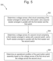
- FIG. 5 is a flowchart representing an illustrative process 500 for determining an operational condition of a push-button switch assembly, in accordance with some examples of the disclosure. While the example shown in FIG. 5 refers to the use of systems 100 and 200 , as shown in FIGS. 1 and 2 , it will be appreciated that the illustrative process shown in FIG. 5 , and any of the other following illustrative processes, may be implemented on systems 100 and 200 , either alone or in combination with any other appropriately configured system architecture.
- a voltage across a first circuit is determined, wherein the first circuit may comprise a first resistor (e.g., resistor R 1 as described in FIG. 2 ) arranged in series with switch S 1 and switch S 3 as described in FIG. 2 , and a second resistor (e.g., resistor R 2 as described in FIG. 2 ) arranged in parallel with the first resistor and switches S 1 and S 3 .
- a first resistor e.g., resistor R 1 as described in FIG. 2
- a second resistor e.g., resistor R 2 as described in FIG. 2
- a voltage across a second circuit is determined, wherein the second circuit may comprise a third resistor (e.g., resistor R 3 as described in FIG. 2 ) arranged in series with switch S 2 and switch S 4 as described in FIG. 2 , and a fourth resistor (e.g., resistor R 4 as described in FIG. 2 ) arranged in parallel with the third resistor and switches S 2 and S 4 .
- a third resistor e.g., resistor R 3 as described in FIG. 2
- a fourth resistor e.g., resistor R 4 as described in FIG. 2
- Switches S 1 /S 3 and switches S 2 /S 4 are closable by displacement of a push-button switch assembly, such as the push-button switch assembly 100 as described above with reference to FIG. 1 and FIG. 2 .
- S 1 and S 3 are arranged in parallel with each other. As such, closure of at least one of S 1 and/or S 3 acts to complete the first circuit 202 as described above. To achieve a more efficient effect of completing the circuit additional switches can be arranged in parallel to S 1 and/or S 3 to complete the first circuit. Similarly, switches, S 2 and S 4 are arranged in parallel with each other. As such, closure of at least one of S 2 and/or S 4 acts to complete the second circuit 204 as described above. To achieve a more efficient effect of completing the circuit additional switches can be arranged in parallel to S 2 and/or S 4 to complete the second circuit.
- an operational condition of the push-button switch assembly is determined based on the voltage across the first circuit and/or the voltage across the second circuit, which is determined based on respective ADC counts (e.g., as described above with reference to FIGS. 3 A and 3 B ).
- FIG. 5 may be used with any other example of this disclosure such as, but not limited to, the example described below in relation to FIGS. 6 and 7 .
- the actions and descriptions described in relation to FIG. 5 may be done in any suitable alternative orders or in parallel to further the purposes of this disclosure.
- FIG. 6 is a flowchart showing optional steps of step 506 from FIG. 5 representing an illustrative process 600 for determining a fault with the first switch S 1 /S 2 of the push-button assembly 100 , in accordance with some examples of the disclosure. While the example shown in FIG. 6 refers to the use of systems 100 and 200 , as shown in FIGS. 1 and 2 , it will be appreciated that the illustrative process shown in FIG. 6 , and any of the other following illustrative processes, may be implemented on systems 100 and 200 , either alone or in combination with any other appropriately configured system architecture.
- Step 602 carries over from step 506 of FIG. 5 .
- a reference voltage Vref (e.g., a 12 V vehicle battery) supplied to the push-button switch assembly 100 is determined (e.g., by a meter reading).
- switch S 1 /S 3 is determined to be closed when the voltage across the first circuit 202 at the reference voltage Vref is within a first predetermined voltage range (Band 1).
- the first predetermined voltage range may correspond to the voltage range calculated from the expected minimum and maximum ADC counts when switch S 1 /S 3 is closed as discussed above with reference to FIGS. 3 A and 3 B .
- the switch S 1 /S 3 is determined to be open when the voltage across the first circuit 202 at the reference voltage Vref is within a second predetermined voltage range (Band 2).
- the second predetermined voltage range may correspond to the voltage range calculated from the expected minimum and maximum ADC counts when switch S 1 /S 3 is open as discussed above with reference to FIGS. 3 A and 3 B .
- the second predetermined voltage range is lower than the first predetermined voltage range. For example, the ADC count is high when the switches are open and the ADC count is low when the switches are closed—in other words voltage measurements are high when the switches are open and low when switches are closed.
- a fault is determined with switch S 1 /S 3 when the voltage across the first circuit 202 is outside of the first predetermined voltage range or the second predetermined voltage range.
- FIG. 7 is a flowchart showing optional steps of step 506 from FIG. 5 representing an illustrative process 700 for determining a fault with switch S 2 /S 4 of the push-button assembly 100 , in accordance with some examples of the disclosure. While the example shown in FIG. 7 refers to the use of systems 100 and 200 , as shown in FIGS. 1 and 2 , it will be appreciated that the illustrative process shown in FIG. 7 , and any of the other following illustrative processes, may be implemented on systems 100 and 200 as well as in combination with illustrative processes 500 and/or 600 , either alone or in combination with any other appropriately configured system architecture.
- a reference voltage Vref (e.g., a 12 V vehicle battery) supplied to the push-button switch assembly 100 is determined (e.g., by a meter reading).
- switch S 2 /S 4 is determined to be closed when the voltage across the second circuit 204 at the reference voltage Vref is within a third predetermined voltage range (Band 3).
- the third predetermined voltage range may correspond to the voltage range calculated from the expected minimum and maximum ADC counts when switch S 2 /S 4 is closed as discussed above with reference to FIGS. 3 A and 3 B .
- switch S 2 /S 4 is determined to be open when the voltage across the second circuit 204 at the reference voltage Vref is within a fourth predetermined voltage range (Band 4) from the expected minimum and maximum ADC counts when switch S 2 /S 4 is open as discussed above with reference to FIGS. 3 A and 3 B .
- the fourth predetermined voltage range is lower than the third predetermined voltage range.
- the ADC count is high when the switches are open and the ADC count is low when the switches are closed—in other words voltage measurements are high when the switches are open and low when switches are closed.
- the third predetermined voltage range and fourth predetermined voltage range may be measured in ADC counts as described above with reference to FIG. 2 and FIGS. 3 A and 3 B .
- a fault is determined with switch S 2 /S 4 when the voltage across the second circuit 204 is outside of the third predetermined voltage range or the fourth predetermined voltage range.
- FIG. 8 is a vehicle 800 having a push-button switch assembly 803 , in accordance with some examples of the disclosure.
- the vehicle 800 has a body 801 housing a motor 802 , shown at the front of the vehicle 800 .
- a push-button switch assembly 803 and a controller 804 (e.g., the controller 200 as described in FIGS. 2 and 4 ).
- the push-button switch assembly 803 is connected via a wiring loom (not shown) to the controller 804 .
- the controller 804 is connected to the motor 802 also via the wiring loom.
- the controller 804 may be operationally coupled to a push-button switch assembly 803 (e.g., the push-button switch assembly 100 as described in FIGS.
- causing the motor 802 of the vehicle 800 to be started or stopped upon operation of the push-button switch assembly 100 by a user may include carrying out, by the controller 200 , 804 , any one of the illustrative processes described above in reference to FIGS. 5 to 7 .
- FIG. 9 is a controller 900 for a push-button switch assembly ( 100 , 803 ), in accordance with some examples of the disclosure.
- controller 900 is similar to that described in FIGS. 1 , 2 , 4 and 8 above (i.e., controller 200 , 804 ).
- the controller 900 has a control circuitry 918 and an input/output (I/O) path 924 .
- the control circuitry 918 carries storage circuitry 920 and processing circuitry 922 .
- the storage circuitry 920 may be at least partly non-volatile.
- the storage circuitry 920 contains program data for instructing the processing circuitry 922 to run one or more programs that process incoming signals from the I/O path 924 and provide output signals via the I/O path 924 .
- the output signals are mainly interpreted by the circuitry that receives them as commands.
- incoming signals include those from the starter switch and output commands include those destined for starter motor operating circuitry.
Landscapes
- Engineering & Computer Science (AREA)
- Chemical & Material Sciences (AREA)
- Combustion & Propulsion (AREA)
- Transportation (AREA)
- Mechanical Engineering (AREA)
- Physics & Mathematics (AREA)
- General Physics & Mathematics (AREA)
- Push-Button Switches (AREA)
Abstract
Description
LSB=Vref/2N
Wherein Vref is Vbat, Nis the number of bits the ADC comprises and 2N is the maximum number of counts the ADC can separate an analog voltage into.
Claims (17)
Priority Applications (3)
| Application Number | Priority Date | Filing Date | Title |
|---|---|---|---|
| US17/545,124 US11869737B2 (en) | 2021-12-08 | 2021-12-08 | Push-button switch assembly and diagnosic methods thereof |
| CN202211577606.2A CN116246901A (en) | 2021-12-08 | 2022-12-05 | Push button switch assembly and diagnostic method thereof |
| DE102022132264.5A DE102022132264A1 (en) | 2021-12-08 | 2022-12-05 | PUSHBUTTON SWITCH ASSEMBLY AND DIAGNOSTIC PROCEDURES THEREOF |
Applications Claiming Priority (1)
| Application Number | Priority Date | Filing Date | Title |
|---|---|---|---|
| US17/545,124 US11869737B2 (en) | 2021-12-08 | 2021-12-08 | Push-button switch assembly and diagnosic methods thereof |
Publications (2)
| Publication Number | Publication Date |
|---|---|
| US20230178323A1 US20230178323A1 (en) | 2023-06-08 |
| US11869737B2 true US11869737B2 (en) | 2024-01-09 |
Family
ID=86498820
Family Applications (1)
| Application Number | Title | Priority Date | Filing Date |
|---|---|---|---|
| US17/545,124 Active 2042-03-09 US11869737B2 (en) | 2021-12-08 | 2021-12-08 | Push-button switch assembly and diagnosic methods thereof |
Country Status (3)
| Country | Link |
|---|---|
| US (1) | US11869737B2 (en) |
| CN (1) | CN116246901A (en) |
| DE (1) | DE102022132264A1 (en) |
Citations (12)
| Publication number | Priority date | Publication date | Assignee | Title |
|---|---|---|---|---|
| US20060043795A1 (en) | 2004-08-31 | 2006-03-02 | Takashi Eguchi | Engine start control device and control method |
| US7216616B2 (en) | 2004-03-26 | 2007-05-15 | Nissan Motor Co., Ltd. | Engine start system and method thereof |
| US7407464B2 (en) | 2005-05-10 | 2008-08-05 | Denso Corporation | Engine start control system |
| US20090225572A1 (en) * | 2005-06-15 | 2009-09-10 | Ameritherm, Inc. | High voltage full bridge circuit and method for operating the same |
| US20120199461A1 (en) * | 2009-10-28 | 2012-08-09 | Alps Electric Korea Co., Ltd. | Engine start/stop switch for a vechicle |
| US20140345555A1 (en) * | 2009-11-19 | 2014-11-27 | Briggs & Stratton Corporation | Push button starting system module for outdoor power equipment |
| CN104570719A (en) | 2014-11-19 | 2015-04-29 | 华晨汽车集团控股有限公司 | Startup button redundancy control device and control method |
| US20150179366A1 (en) * | 2012-07-25 | 2015-06-25 | U-Shin Ltd. | Switch device |
| US20150308566A1 (en) * | 2014-04-29 | 2015-10-29 | GM Global Technology Operations LLC | Push-button shifter assembly with button state determination logic |
| US9543089B2 (en) | 2012-07-25 | 2017-01-10 | U-Shin Ltd. | Switch device |
| CN209247981U (en) | 2018-10-11 | 2019-08-13 | 云南力帆骏马车辆有限公司 | A kind of ignition switch detection circuit and vehicle |
| US10598142B2 (en) | 2017-10-10 | 2020-03-24 | Kabushiki Kaisha Tokai Rika Denki Seisakusho | Illuminated momentary push button switch |
-
2021
- 2021-12-08 US US17/545,124 patent/US11869737B2/en active Active
-
2022
- 2022-12-05 CN CN202211577606.2A patent/CN116246901A/en active Pending
- 2022-12-05 DE DE102022132264.5A patent/DE102022132264A1/en active Pending
Patent Citations (12)
| Publication number | Priority date | Publication date | Assignee | Title |
|---|---|---|---|---|
| US7216616B2 (en) | 2004-03-26 | 2007-05-15 | Nissan Motor Co., Ltd. | Engine start system and method thereof |
| US20060043795A1 (en) | 2004-08-31 | 2006-03-02 | Takashi Eguchi | Engine start control device and control method |
| US7407464B2 (en) | 2005-05-10 | 2008-08-05 | Denso Corporation | Engine start control system |
| US20090225572A1 (en) * | 2005-06-15 | 2009-09-10 | Ameritherm, Inc. | High voltage full bridge circuit and method for operating the same |
| US20120199461A1 (en) * | 2009-10-28 | 2012-08-09 | Alps Electric Korea Co., Ltd. | Engine start/stop switch for a vechicle |
| US20140345555A1 (en) * | 2009-11-19 | 2014-11-27 | Briggs & Stratton Corporation | Push button starting system module for outdoor power equipment |
| US20150179366A1 (en) * | 2012-07-25 | 2015-06-25 | U-Shin Ltd. | Switch device |
| US9543089B2 (en) | 2012-07-25 | 2017-01-10 | U-Shin Ltd. | Switch device |
| US20150308566A1 (en) * | 2014-04-29 | 2015-10-29 | GM Global Technology Operations LLC | Push-button shifter assembly with button state determination logic |
| CN104570719A (en) | 2014-11-19 | 2015-04-29 | 华晨汽车集团控股有限公司 | Startup button redundancy control device and control method |
| US10598142B2 (en) | 2017-10-10 | 2020-03-24 | Kabushiki Kaisha Tokai Rika Denki Seisakusho | Illuminated momentary push button switch |
| CN209247981U (en) | 2018-10-11 | 2019-08-13 | 云南力帆骏马车辆有限公司 | A kind of ignition switch detection circuit and vehicle |
Also Published As
| Publication number | Publication date |
|---|---|
| DE102022132264A1 (en) | 2023-06-15 |
| US20230178323A1 (en) | 2023-06-08 |
| CN116246901A (en) | 2023-06-09 |
Similar Documents
| Publication | Publication Date | Title |
|---|---|---|
| KR101887903B1 (en) | An apparatus and a method for testing a failure of resistive sensors | |
| US20050078423A1 (en) | Controller for electric power supply of electronic device supplied with electric power from battery of vehicle | |
| US11571988B2 (en) | High-voltage relay system for vehicle and diagnostic method therefor | |
| JP2000098008A (en) | Device and method for monitoring and displaying state, of on-vehicle battery | |
| US20150115873A1 (en) | On-board charger for eco-friendly vehicle | |
| CN110662975B (en) | Relay diagnosis circuit | |
| JPH05131864A (en) | Device to detect variable ratio of automobile | |
| US6960918B2 (en) | Method and apparatus for control and fault detection of a remote electrical motor | |
| JP2020078149A (en) | Electric vehicle | |
| US11869737B2 (en) | Push-button switch assembly and diagnosic methods thereof | |
| CN107533108A (en) | The condition estimating device and method for estimating state of secondary cell | |
| US7156065B2 (en) | Trigger circuit for an engine starter relay | |
| US3293443A (en) | Vehicle power converter | |
| CN103376407A (en) | Method and arrangement for diagnosing drivers of contactors, battery, and motor vehicle having such a battery | |
| JP2020078151A (en) | Electric vehicle | |
| US11292413B2 (en) | Means of locomotion, arrangement and device for evaluating a signal of an airbag control unit | |
| US20230178310A1 (en) | Starting a vehicle motor | |
| KR101684096B1 (en) | Apparatus for detecting fault of relay in PHEV | |
| KR20100027748A (en) | Method for diagonisign power dividing module of engine starting apparatus | |
| JP3486017B2 (en) | Engine ignition device for vehicles | |
| US12567536B2 (en) | Ignition coil assembly with internal diagnostic features | |
| CN112114277B (en) | Method for determining the connection state of at least one connection component | |
| FR3067122B1 (en) | DIAGNOSIS OF AN AUTOMOTIVE VEHICLE ELECTRIC CHARGE | |
| US20230258738A1 (en) | Method and device for detecting a short circuit in an h-bridge electronic circuit | |
| US7013868B2 (en) | Accelerator signal offset system |
Legal Events
| Date | Code | Title | Description |
|---|---|---|---|
| AS | Assignment |
Owner name: FORD GLOBAL TECHNOLOGIES, LLC, MICHIGAN Free format text: ASSIGNMENT OF ASSIGNORS INTEREST;ASSIGNORS:BRAITHWAITE, PAUL;SCHECK, MARTIN;WEINFURTHER, JAMES MICHAEL;AND OTHERS;SIGNING DATES FROM 20211201 TO 20211207;REEL/FRAME:058332/0992 |
|
| FEPP | Fee payment procedure |
Free format text: ENTITY STATUS SET TO UNDISCOUNTED (ORIGINAL EVENT CODE: BIG.); ENTITY STATUS OF PATENT OWNER: LARGE ENTITY |
|
| AS | Assignment |
Owner name: FORD GLOBAL TECHNOLOGIES, LLC, MICHIGAN Free format text: ASSIGNMENT OF ASSIGNORS INTEREST;ASSIGNOR:REED, ERIC L.;REEL/FRAME:058470/0320 Effective date: 20211223 |
|
| STPP | Information on status: patent application and granting procedure in general |
Free format text: RESPONSE TO EX PARTE QUAYLE ACTION ENTERED AND FORWARDED TO EXAMINER |
|
| STPP | Information on status: patent application and granting procedure in general |
Free format text: NOTICE OF ALLOWANCE MAILED -- APPLICATION RECEIVED IN OFFICE OF PUBLICATIONS |
|
| STPP | Information on status: patent application and granting procedure in general |
Free format text: PUBLICATIONS -- ISSUE FEE PAYMENT RECEIVED |
|
| STPP | Information on status: patent application and granting procedure in general |
Free format text: PUBLICATIONS -- ISSUE FEE PAYMENT VERIFIED |
|
| STCF | Information on status: patent grant |
Free format text: PATENTED CASE |