US11869367B2 - Device and method for controlling flight of unmanned aerial vehicle - Google Patents
Device and method for controlling flight of unmanned aerial vehicle Download PDFInfo
- Publication number
- US11869367B2 US11869367B2 US17/354,578 US202117354578A US11869367B2 US 11869367 B2 US11869367 B2 US 11869367B2 US 202117354578 A US202117354578 A US 202117354578A US 11869367 B2 US11869367 B2 US 11869367B2
- Authority
- US
- United States
- Prior art keywords
- unmanned aerial
- aerial vehicle
- flight route
- flight
- point
- Prior art date
- Legal status (The legal status is an assumption and is not a legal conclusion. Google has not performed a legal analysis and makes no representation as to the accuracy of the status listed.)
- Active, expires
Links
Images


Classifications
-
- G—PHYSICS
- G05—CONTROLLING; REGULATING
- G05D—SYSTEMS FOR CONTROLLING OR REGULATING NON-ELECTRIC VARIABLES
- G05D1/00—Control of position, course, altitude or attitude of land, water, air or space vehicles, e.g. using automatic pilots
- G05D1/40—Control within particular dimensions
- G05D1/46—Control of position or course in three dimensions
-
- G—PHYSICS
- G05—CONTROLLING; REGULATING
- G05D—SYSTEMS FOR CONTROLLING OR REGULATING NON-ELECTRIC VARIABLES
- G05D1/00—Control of position, course, altitude or attitude of land, water, air or space vehicles, e.g. using automatic pilots
- G05D1/10—Simultaneous control of position or course in three dimensions
- G05D1/101—Simultaneous control of position or course in three dimensions specially adapted for aircraft
-
- G08G5/003—
-
- B—PERFORMING OPERATIONS; TRANSPORTING
- B64—AIRCRAFT; AVIATION; COSMONAUTICS
- B64C—AEROPLANES; HELICOPTERS
- B64C39/00—Aircraft not otherwise provided for
- B64C39/02—Aircraft not otherwise provided for characterised by special use
- B64C39/024—Aircraft not otherwise provided for characterised by special use of the remote controlled vehicle type, i.e. RPV
-
- G—PHYSICS
- G01—MEASURING; TESTING
- G01C—MEASURING DISTANCES, LEVELS OR BEARINGS; SURVEYING; NAVIGATION; GYROSCOPIC INSTRUMENTS; PHOTOGRAMMETRY OR VIDEOGRAMMETRY
- G01C21/00—Navigation; Navigational instruments not provided for in groups G01C1/00 - G01C19/00
- G01C21/20—Instruments for performing navigational calculations
-
- G—PHYSICS
- G05—CONTROLLING; REGULATING
- G05D—SYSTEMS FOR CONTROLLING OR REGULATING NON-ELECTRIC VARIABLES
- G05D1/00—Control of position, course, altitude or attitude of land, water, air or space vehicles, e.g. using automatic pilots
- G05D1/0005—Control of position, course, altitude or attitude of land, water, air or space vehicles, e.g. using automatic pilots with arrangements to save energy
-
- G—PHYSICS
- G05—CONTROLLING; REGULATING
- G05D—SYSTEMS FOR CONTROLLING OR REGULATING NON-ELECTRIC VARIABLES
- G05D1/00—Control of position, course, altitude or attitude of land, water, air or space vehicles, e.g. using automatic pilots
- G05D1/60—Intended control result
- G05D1/644—Optimisation of travel parameters, e.g. of energy consumption, journey time or distance
-
- G—PHYSICS
- G05—CONTROLLING; REGULATING
- G05D—SYSTEMS FOR CONTROLLING OR REGULATING NON-ELECTRIC VARIABLES
- G05D1/00—Control of position, course, altitude or attitude of land, water, air or space vehicles, e.g. using automatic pilots
- G05D1/60—Intended control result
- G05D1/646—Following a predefined trajectory, e.g. a line marked on the floor or a flight path
-
- G08G5/0013—
-
- G08G5/006—
-
- G08G5/0069—
-
- G—PHYSICS
- G08—SIGNALLING
- G08G—TRAFFIC CONTROL SYSTEMS
- G08G5/00—Traffic control systems for aircraft
- G08G5/20—Arrangements for acquiring, generating, sharing or displaying traffic information
- G08G5/22—Arrangements for acquiring, generating, sharing or displaying traffic information located on the ground
-
- G—PHYSICS
- G08—SIGNALLING
- G08G—TRAFFIC CONTROL SYSTEMS
- G08G5/00—Traffic control systems for aircraft
- G08G5/20—Arrangements for acquiring, generating, sharing or displaying traffic information
- G08G5/26—Transmission of traffic-related information between aircraft and ground stations
-
- G—PHYSICS
- G08—SIGNALLING
- G08G—TRAFFIC CONTROL SYSTEMS
- G08G5/00—Traffic control systems for aircraft
- G08G5/30—Flight plan management
-
- G—PHYSICS
- G08—SIGNALLING
- G08G—TRAFFIC CONTROL SYSTEMS
- G08G5/00—Traffic control systems for aircraft
- G08G5/30—Flight plan management
- G08G5/32—Flight plan management for flight plan preparation
-
- G—PHYSICS
- G08—SIGNALLING
- G08G—TRAFFIC CONTROL SYSTEMS
- G08G5/00—Traffic control systems for aircraft
- G08G5/50—Navigation or guidance aids
- G08G5/55—Navigation or guidance aids for a single aircraft
-
- G—PHYSICS
- G08—SIGNALLING
- G08G—TRAFFIC CONTROL SYSTEMS
- G08G5/00—Traffic control systems for aircraft
- G08G5/50—Navigation or guidance aids
- G08G5/57—Navigation or guidance aids for unmanned aircraft
-
- G—PHYSICS
- G08—SIGNALLING
- G08G—TRAFFIC CONTROL SYSTEMS
- G08G5/00—Traffic control systems for aircraft
- G08G5/50—Navigation or guidance aids
- G08G5/59—Navigation or guidance aids in accordance with predefined flight zones, e.g. to avoid prohibited zones
-
- B—PERFORMING OPERATIONS; TRANSPORTING
- B64—AIRCRAFT; AVIATION; COSMONAUTICS
- B64U—UNMANNED AERIAL VEHICLES [UAV]; EQUIPMENT THEREFOR
- B64U2201/00—UAVs characterised by their flight controls
- B64U2201/10—UAVs characterised by their flight controls autonomous, i.e. by navigating independently from ground or air stations, e.g. by using inertial navigation systems [INS]
-
- G—PHYSICS
- G05—CONTROLLING; REGULATING
- G05D—SYSTEMS FOR CONTROLLING OR REGULATING NON-ELECTRIC VARIABLES
- G05D2109/00—Types of controlled vehicles
- G05D2109/20—Aircraft, e.g. drones
Definitions
- the present disclosure relates to a technology for controlling flight of an unmanned aerial vehicle based on a navigation route of a vehicle (a route from a departure point to a destination).
- Such technologies have a problem of not being able to efficiently acquire the environment information because a performance (a sensing range) of a sensor applied to an unmanned aerial vehicle, a flight available distance based on a fuel amount (including a remaining amount of battery), and a performance (a distance at which communication with the vehicle is available) of a communication device are not considered in controlling flight of the unmanned aerial vehicle for acquiring the environment information on the route from the departure point to the destination of the vehicle.
- An aspect of the present disclosure provides a device and a method for controlling flight of an unmanned aerial vehicle that may efficiently acquire environment information required to create a navigation route of a vehicle by generating a flight route of the unmanned aerial vehicle corresponding to a travel route from a departure point to a destination of the vehicle based on a performance of a sensor mounted on the unmanned aerial vehicle, a flight available distance based on a fuel amount (a battery remaining capacity), and a performance of a communication device, and operating the unmanned aerial vehicle to follow the generated flight route.
- a device for controlling flight of an unmanned aerial vehicle may include a receiver configured to receive departure point information and destination information of a vehicle, and a controller configured to generate a flight route corresponding to a travel route from a departure point to a destination of the vehicle based on at least one of a sensing range of a sensor mounted on the unmanned aerial vehicle, a flight available distance based on a fuel amount, and/or a communication available distance of a communication device mounted on the unmanned aerial vehicle, and operate the unmanned aerial vehicle to follow the generated flight route.
- the controller may be configured to detect a center point on a straight line connecting the departure point and the destination with each other, detect a first point on the travel route located farthest from the center point, and detect a sensing region having a straight line connecting the center point and the first point with each other as a radius.
- the controller may be configured to generate a first flight route for flying in a direction of the straight line from the departure point to the center point when the sensing region is contained in a reference region.
- the controller may be configured to operate the unmanned aerial vehicle to wait at the center point until the vehicle arrives at the destination when the unmanned aerial vehicle arrives at the center point along the first flight route. In one implementation, the controller may be configured to operate the unmanned aerial vehicle to only fly from the departure point to a maximum reach point along the first flight route when the first flight route exceeds a reference distance.
- the controller may be configured to calculate a total distance required to return to a specified place after flying along the first flight route from the departure point as the flight available distance. In one implementation, the controller may be configured to generate a second flight route for flying along the travel route when the sensing region is not contained in a reference region. In one implementation, the controller may be configured to operate the unmanned aerial vehicle to follow the second flight route while maintaining a spaced distance from the vehicle within the communication available distance.
- the controller may be configured to operate the unmanned aerial vehicle to fly only from the departure point to a maximum reach point along the second flight route when the second flight route exceeds a reference distance.
- the controller may be configured to operate the unmanned aerial vehicle to fly only from the departure point to a maximum reach point along the second flight route while maintaining a spaced distance from the vehicle within the communication available distance when the second flight route exceeds a reference distance.
- a method for controlling flight of an unmanned aerial vehicle may include receiving, by a receiver, departure point information and destination information of a vehicle, generating, by a controller, a flight route corresponding to a travel route from a departure point to a destination of the vehicle based on at least one of a sensing range of a sensor mounted on the unmanned aerial vehicle, a flight available distance based on a fuel amount, and/or a communication available distance of a communication device mounted on the unmanned aerial vehicle, and operating, by the controller, the unmanned aerial vehicle to follow the created flight route.
- the generating of the flight route may include detecting a center point on a straight line connecting the departure point and the destination with each other, detecting a first point on the travel route located farthest from the center point, and detecting a sensing region having a straight line connecting the center point and the first point with each other as a radius.
- the generating of the flight route may further include creating a first flight route for flying in a direction of the straight line from the departure point to the center point when the sensing region is contained in a reference region.
- the operating of the unmanned aerial vehicle may include making the unmanned aerial vehicle wait at the center point until the vehicle arrives at the destination when the unmanned aerial vehicle arrives at the center point along the first flight route.
- the operating of the unmanned aerial vehicle may include operating the unmanned aerial vehicle to only fly from the departure point to a maximum reach point along the first flight route when the first flight route exceeds a reference distance.
- the generating of the flight route may include calculating a total distance required to return to a specified place after flying along the first flight route from the departure point as the flight available distance.
- the generating of the flight route may further include generating a second flight route for flying along the travel route when the sensing region is not contained in a reference region.
- the operating of the unmanned aerial vehicle may include operating the unmanned aerial vehicle to follow the second flight route while maintaining a spaced distance from the vehicle within the communication available distance.
- the operating of the unmanned aerial vehicle may include operating the unmanned aerial vehicle to fly only from the departure point to a maximum reach point along the second flight route when the second flight route exceeds a reference distance.
- the operating of the unmanned aerial vehicle may include operating the unmanned aerial vehicle to fly only from the departure point to a maximum reach point along the second flight route while maintaining a spaced distance from the vehicle within the communication available distance when the second flight route exceeds a reference distance.
- FIG. 1 is a block diagram of a device for controlling flight of an unmanned aerial vehicle according to an exemplary embodiment of the present disclosure
- FIG. 2 is an exemplary diagram illustrating a sensing region detected by a controller equipped in a device for controlling flight of an unmanned aerial vehicle according to an exemplary embodiment of the present disclosure
- FIG. 3 is an exemplary diagram illustrating a flight route of an unmanned aerial vehicle generated by a controller equipped in a device for controlling flight of the unmanned aerial vehicle according to an exemplary embodiment of the present disclosure
- FIG. 4 is another exemplary diagram illustrating a flight route of an unmanned aerial vehicle generated by a controller equipped in a device for controlling flight of an unmanned aerial vehicle according to an exemplary embodiment of the present disclosure
- FIG. 5 is a flowchart of a method for controlling flight of an unmanned aerial vehicle according to an exemplary embodiment of the present disclosure.
- controller/control unit refers to a hardware device that includes a memory and a processor and is specifically programmed to execute the processes described herein.
- the memory is configured to store the modules and the processor is specifically configured to execute said modules to perform one or more processes which are described further below.
- control logic of the present disclosure may be embodied as non-transitory computer readable media on a computer readable medium containing executable program instructions executed by a processor, controller/control unit or the like.
- the computer readable mediums include, but are not limited to, ROM, RAM, compact disc (CD)-ROMs, magnetic tapes, floppy disks, flash drives, smart cards and optical data storage devices.
- the computer readable recording medium can also be distributed in network coupled computer systems so that the computer readable media is stored and executed in a distributed fashion, e.g., by a telematics server or a Controller Area Network (CAN).
- a telematics server or a Controller Area Network (CAN).
- CAN Controller Area Network
- the term “about” is understood as within a range of normal tolerance in the art, for example within 2 standard deviations of the mean. “About” can be understood as within 10%, 9%, 8%, 7%, 6%, 5%, 4%, 3%, 2%, 1%, 0.5%, 0.1%, 0.05%, or 0.01% of the stated value. Unless otherwise clear from the context, all numerical values provided herein are modified by the term “about.”
- FIG. 1 is a block diagram of a device for controlling flight of an unmanned aerial vehicle according to an exemplary embodiment of the present disclosure.
- a device 100 for controlling flight of an unmanned aerial vehicle may include storage 10 , a first communication device 20 , a second communication device 30 , and a controller 40 .
- components may be coupled to each other to be implemented as one component, or some components may be omitted depending on a scheme for implementing the device 100 for controlling the flight of the unmanned aerial vehicle according to an exemplary embodiment of the present disclosure.
- the first communication device 20 and the second communication device 30 may be integrated into one module.
- the storage 10 may be configured to store various logics, algorithms, and programs required in a process of generating a flight route of an unmanned aerial vehicle 300 corresponding to a route from a departure point to a destination of a vehicle based on a performance of a sensor mounted on the unmanned aerial vehicle 300 , a flight available distance based on a fuel amount (a battery remaining capacity), and a performance of a communication device, and operating the unmanned aerial vehicle 300 to follow the generated flight route.
- the sensor may include at least one of a GPS, a camera, a radar, and/or a lidar.
- the storage 10 may include at least one type of recording media (storage media) of a memory of a flash memory type, a hard disk type, a micro type, a card type (e.g., a secure digital card (SD card) or an eXtream digital card (XD card)), and the like, and/or a memory of a random access memory (RAM), a static RAM (SRAM), a read-only memory (ROM), a programmable ROM (PROM), an electrically erasable PROM (EEPROM), a magnetic RAM (MRAM), a magnetic disk, and an optical disk type.
- recording media storage media
- storage media of a memory of a flash memory type, a hard disk type, a micro type, a card type (e.g., a secure digital card (SD card) or an eXtream digital card (XD card)), and the like, and/or a memory of a random access memory (RAM), a static RAM (SRAM), a read-only memory (ROM),
- the first communication device 20 which is a module that provides an interface for communication with a vehicle terminal 200 , may be configured to receive departure point information and destination information from the vehicle terminal 200 , and transmit environment information on the route from the departure point to the destination of the vehicle to the vehicle terminal 200 .
- the environment information may include traffic information (accident information, traffic information, and the like), road information (road control information, construction information, toll information, and the like), and weather information (snow, rain, and the like).
- the first communication device 20 which is a module that provides an interface for communication with a telematics server 400 , may be configured to receive the departure point information and the destination information from the telematics server 400 .
- the first communication device 20 may be configured to receive a travel route corresponding to the departure point information and the destination information of the vehicle from the telematics server 400 .
- the first communication device 20 may include at least one of a mobile communication module, a wireless Internet module, and/or a short-range communication module as a data transmission/reception module.
- the mobile communication module may be configured to communicate with the vehicle terminal 200 via a mobile communication network built based on technical standards or communication schemes for mobile communication (e.g., a global system for mobile communication (GSM), a code division multi access (CDMA), a code division multi access 2000 (CDMA2000), an enhanced voice-data optimized or enhanced voice-data only (EV-DO), a wideband CDMA (WCDMA), a high speed downlink packet access (HSDPA), a high speed uplink packet access (HSUPA), a long term evolution (LTE), a long term evolution-advanced (LTEA), a 4th generation mobile telecommunication (4G), a 5th generation mobile telecommunication (5G), and the like).
- GSM global system for mobile communication
- CDMA code division multi access
- CDMA2000 code division multi access 2000
- EV-DO enhanced voice-data optimized or enhanced voice-data only
- WCDMA wideband CDMA
- HSDPA high speed downlink packet access
- HSUPA high speed uplink packet access
- the wireless Internet module which is a module for wireless Internet access, may be configured to communicate with the vehicle terminal 200 via a wireless LAN (WLAN), a wireless-fidelity (Wi-Fi), a wireless fidelity (Wi-Fi) Direct, a digital living network alliance (DLNA), a wireless broadband (WiBro), a world interoperability for microwave access (WiMAX), a high speed downlink packet access (HSDPA), a high speed uplink packet access (HSUPA), a long term evolution (LTE), a long term evolution-advanced (LTE-A), and the like.
- WLAN wireless LAN
- Wi-Fi wireless-fidelity
- Wi-Fi wireless fidelity
- WiBro wireless broadband
- WiMAX world interoperability for microwave access
- HSDPA high speed downlink packet access
- HSUPA high speed uplink packet access
- LTE long term evolution
- LTE-A long term evolution-advanced
- the short-range communication module may support short-range communication using at least one of technologies of a BluetoothTM, a radio frequency identification (RFID), an infrared data association (IrDA), an ultra wideband (UWB), a ZigBee, a near field communication (NFC), and/or a wireless universal serial bus (Wireless USB).
- RFID radio frequency identification
- IrDA infrared data association
- UWB ultra wideband
- ZigBee ultra wideband
- NFC near field communication
- Wi-US wireless universal serial bus
- the second communication device 30 which is a module that provides an interface for communication with the unmanned aerial vehicle 300 , may be configured to receive sensor information (a sensing range of the sensor), fuel amount information (battery remaining capacity information), and communication device information (a communication available distance of the communication device) from the unmanned aerial vehicle 300 , and transmit the flight route of the unmanned aerial vehicle 300 corresponding to the route from the departure point to the destination of the vehicle to the unmanned aerial vehicle 300 .
- the communication available distance of the communication device refers to a distance in which both a specification aspect and an environmental aspect (a transmission/reception sensitivity) of the communication device are considered.
- the second communication device 30 may include the short-range communication module as the data transmission/reception module.
- the short-range communication module may support short-range communication using at least one of technologies of a BluetoothTM, a radio frequency identification (RFID), an infrared communication (an infrared data association; IrDA), an ultra wideband (UWB), a ZigBee, a near field communication (NFC), and/or a wireless Universal Serial BUS (USB).
- RFID radio frequency identification
- IrDA infrared communication
- UWB ultra wideband
- ZigBee ZigBee
- NFC near field communication
- USB wireless Universal Serial BUS
- the controller 40 may be configured to perform overall control such that each of the components may normally perform a function thereof.
- the controller 40 may be implemented in a form of hardware, software, or a combination of the hardware and the software.
- the controller 40 may be implemented as a microprocessor, but may not be limited thereto.
- the controller 40 may be configured to perform various controls in the process of generating the flight route of the unmanned aerial vehicle 300 corresponding to the route from the departure point to the destination of the vehicle in consideration of the performance of the sensor mounted on the unmanned aerial vehicle 300 , the flight available distance based on the fuel amount (the battery remaining capacity), and the performance of the communication device, and operating the unmanned aerial vehicle 300 to follow the generated flight route.
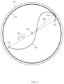
- FIG. 2 is an exemplary diagram illustrating a sensing region detected by a controller equipped in a device for controlling flight of an unmanned aerial vehicle according to an exemplary embodiment of the present disclosure.
- ‘ 210 ’ represents the departure point (or a current location) of the vehicle
- ‘ 220 ’ represents the destination
- ‘ 230 ’ represents a center point of a straight line connecting the departure point 210 and the destination 220 with each other
- ‘ 240 ’ represents a travel route of the vehicle from the departure point 210 to the destination 220
- ‘ 250 ’ represents a point on the route 240 located farthest from the center point 230
- ‘ 260 ’ represents a straight line (a sensing radius) connecting the center point 230 and the point 250 with each other
- ‘ 270 ’ represents a circle (a sensing region) formed by the sensing radius 260 .
- the controller 40 may be configured to generate the straight line connecting the departure point 210 and the destination 220 with each other, detect the center point 230 of the straight line, detect the point 250 on the travel route 240 located farthest from the center point 230 on the travel route 240 from the departure point 210 to the destination 220 , and detect the sensing region 270 having the radius 260 of the straight line connecting the center point 230 and the point 250 with each other.
- FIG. 3 is an exemplary diagram illustrating a flight route of an unmanned aerial vehicle generated by a controller equipped in a device for controlling flight of the unmanned aerial vehicle according to an exemplary embodiment of the present disclosure.
- the controller 40 equipped in the device for controlling the flight of the unmanned aerial vehicle may be configured to generate a flight route 320 flying in a direction of the straight line from the departure point 210 to the center point 230 of the sensing region 270 when the sensing region 270 corresponding to the travel route 240 from the departure point 210 to the destination 220 is contained in a reference region 310 (when the radius of the sensing region 270 is equal to or less than a radius of the reference region 310 ).
- the reference region 310 may represent a maximum sensing region of the sensor disposed on the unmanned aerial vehicle 300 , and the reference region 310 may be determined based on the performance of the sensor disposed on the unmanned aerial vehicle 300 .
- the controller 40 may be configured to operate the unmanned aerial vehicle 300 to wait at the center point 230 until the vehicle arrives at the destination 220 without immediately returning the unmanned aerial vehicle 300 to a specified place (e.g., a nearby charging station, a waiting station, and the like).
- a specified place e.g., a nearby charging station, a waiting station, and the like.
- the controller 40 may be configured to return the unmanned aerial vehicle 300 , which is in circular flight at the center point 230 , to the specified place.
- the controller 40 may be configured to generate the flight route of the unmanned aerial vehicle 300 by further considering the flight available distance based on the fuel amount of the unmanned aerial vehicle 300 .
- the flight available distance based on the fuel amount of the unmanned aerial vehicle 300 refers to a total distance required to return to the specified place after flying along the flight route 320 from the departure point 210 .
- the flight available distance may be calculated by the controller 40 .
- the controller 40 may be configured to maintain the flight route 320 when the flight route 320 of the unmanned aerial vehicle 300 is less than a reference distance, and may be configured to generate a new flight route for only traveling from the departure point 210 to a maximum reach point along the flight route 320 when the flight route 320 of the unmanned aerial vehicle 300 exceeds the reference distance.
- the reference distance refers to a distance obtained by subtracting a return distance from the flight available distance based on the fuel amount of the unmanned aerial vehicle 300
- the maximum reach point means a point at which the unmanned aerial vehicle 300 must change a direction thereof to the return place because of a residual fuel amount after flying along the flight route 320 from the departure point 210 .
- the controller 40 may be configured to generate a flight route from the departure point 210 to an arbitrary point located between the departure point 210 and the maximum reach point. This is because it may be more advantageous for the unmanned aerial vehicle 300 to fly only to the arbitrary point ahead of the maximum reach point in terms of fuel consumption and information provision to the vehicle rather than to fly to the maximum reach point.
- the controller 40 may also be configured to generate the flight route of the unmanned aerial vehicle 300 by further considering the flight available distance based on the fuel amount of the unmanned aerial vehicle 300 and the performance (the communication available distance) of the communication device equipped in the unmanned aerial vehicle 300 .
- the controller 40 may be configured to operate the unmanned aerial vehicle 300 to follow the flight route 320 while maintaining a spaced distance from the vehicle within the communication available distance when the flight route 320 of the unmanned aerial vehicle 300 is less than the reference distance, and operate the unmanned aerial vehicle 300 to fly only to the maximum reach point along the flight route 320 from the departure point 210 while maintaining the spaced distance from the vehicle within the communication available distance when the flight route 320 of the unmanned aerial vehicle 300 exceeds the reference distance.
- FIG. 4 is another exemplary diagram illustrating a flight route of an unmanned aerial vehicle generated by a controller equipped in a device for controlling flight of an unmanned aerial vehicle according to an embodiment of the present disclosure.
- the controller 40 equipped in the device for controlling the flight of the unmanned aerial vehicle according to an exemplary embodiment of the present disclosure may be configured to generate a flight route 410 for flying along the travel route 240 from the departure point 210 to the destination 220 .
- the controller 40 may be configured to operate the unmanned aerial vehicle 300 to wait at the destination 220 until the vehicle arrives at the destination 220 without immediately returning the unmanned aerial vehicle 300 to the specified place (e.g., the nearby charging station, the waiting station, and the like). In other words, when the vehicle arrives at the destination 220 , the controller 40 may be configured to return the unmanned aerial vehicle 300 , which is in the circular flight at the destination 220 , to the specified place.
- the specified place e.g., the nearby charging station, the waiting station, and the like.
- the controller 40 may be configured to generate the flight route of the unmanned aerial vehicle 300 by further considering the flight available distance based on the fuel amount of the unmanned aerial vehicle 300 .
- the flight available distance of the unmanned aerial vehicle 300 refers to a distance required to return to the specified place after flying along the flight route 410 from the departure point 210 .
- the flight available distance may be calculated by the controller 40 .
- the controller 40 may be configured to maintain the flight route 410 in response to determining that the flight route 410 of the unmanned aerial vehicle 300 is less than the reference distance, and generate a new flight route for only traveling from the departure point 210 to the maximum reach point along the flight route 410 in response to determining that the flight route 410 of the unmanned aerial vehicle 300 exceeds the reference distance.
- the reference distance refers to the distance obtained by subtracting the return distance from the flight available distance based on the fuel amount of the unmanned aerial vehicle 300
- the maximum reach point refers to a point at which the unmanned aerial vehicle 300 must change the direction thereof to the return place because of a residual fuel amount after flying along the flight route 410 from the departure point 210 .
- the controller 40 may be configured to generate a flight route for flying from the departure point 210 to an arbitrary point located between the departure point 210 and the maximum reach point. This is because it may be more advantageous for the unmanned aerial vehicle 300 to fly only to the arbitrary point ahead of the maximum reach point in terms of the fuel consumption and the information provision to the vehicle rather than to fly to the maximum reach point.
- the controller 40 may also be configured to generate the flight route of the unmanned aerial vehicle 300 by further considering the flight available distance based on the fuel amount of the unmanned aerial vehicle 300 and the performance (the communication available distance) of the communication device equipped in the unmanned aerial vehicle 300 .
- the controller 40 may be configured to operate the unmanned aerial vehicle 300 to follow the flight route 410 while maintaining the spaced distance from the vehicle within the communication available distance when the flight route 410 of the unmanned aerial vehicle 300 is less than the reference distance, and operate the unmanned aerial vehicle 300 to fly only to the maximum reach point along the flight route 410 from the departure point 210 while maintaining the spaced distance from the vehicle within the communication available distance when the flight route 410 of the unmanned aerial vehicle 300 exceeds the reference distance.
- the device 100 for controlling the flight of the unmanned aerial vehicle may be mounted on the telematics server 400 or on the unmanned aerial vehicle 300 .
- the device 100 may be configured to generate the flight route of the unmanned aerial vehicle 300 in conjunction with the vehicle terminal 200 when being mounted on the telematics server 400 , and may be configured to control the flight of the unmanned aerial vehicle 300 in conjunction with the vehicle terminal 200 when being mounted on the unmanned aerial vehicle 300 .
- FIG. 5 is a flowchart of a method for controlling flight of an unmanned aerial vehicle according to an exemplary embodiment of the present disclosure.
- the first communication device 20 may be configured to receive the departure point information and the destination information of the vehicle from the vehicle terminal 200 or the telematics server 400 ( 501 ).
- the controller 40 may be configured to generate the flight route corresponding to the travel route from the departure point to the destination of the vehicle in consideration of at least one of the sensing range of the sensor mounted on the unmanned aerial vehicle, the flight available distance based on the fuel amount, and/or the communication available distance of the communication device mounted on the unmanned aerial vehicle ( 502 ).
- the controller 40 may be configured to operate the unmanned aerial vehicle to follow the created flight route ( 503 ).
- the exemplary embodiments disclosed in the present disclosure are not intended to limit the technical idea of the present disclosure but to illustrate the present disclosure, and the scope of the technical idea of the present disclosure is not limited by the exemplary embodiments.
- the scope of the present disclosure should be construed as being covered by the scope of the appended claims, and all technical ideas falling within the scope of the claims should be construed as being included in the scope of the present disclosure.
- the device and the method for controlling the flight of the unmanned aerial vehicle may efficiently acquire the environment information required to create the navigation route of the vehicle by generating the flight route of the unmanned aerial vehicle corresponding to the travel route from the departure point to the destination of the vehicle in consideration of the performance of the sensor mounted on the unmanned aerial vehicle, the flight available distance based on the fuel amount (the battery remaining capacity), and the performance of the communication device, and operating the unmanned aerial vehicle to follow the generated flight route.
Landscapes
- Engineering & Computer Science (AREA)
- Physics & Mathematics (AREA)
- General Physics & Mathematics (AREA)
- Aviation & Aerospace Engineering (AREA)
- Radar, Positioning & Navigation (AREA)
- Remote Sensing (AREA)
- Automation & Control Theory (AREA)
- Navigation (AREA)
- Traffic Control Systems (AREA)
Abstract
Description
Claims (18)
Applications Claiming Priority (2)
| Application Number | Priority Date | Filing Date | Title |
|---|---|---|---|
| KR10-2020-0164972 | 2020-11-30 | ||
| KR1020200164972A KR20220076127A (en) | 2020-11-30 | 2020-11-30 | Apparatus for controlling flight of unmanned aerial vehicle and method thereof |
Publications (2)
| Publication Number | Publication Date |
|---|---|
| US20220172627A1 US20220172627A1 (en) | 2022-06-02 |
| US11869367B2 true US11869367B2 (en) | 2024-01-09 |
Family
ID=81752725
Family Applications (1)
| Application Number | Title | Priority Date | Filing Date |
|---|---|---|---|
| US17/354,578 Active 2042-04-08 US11869367B2 (en) | 2020-11-30 | 2021-06-22 | Device and method for controlling flight of unmanned aerial vehicle |
Country Status (3)
| Country | Link |
|---|---|
| US (1) | US11869367B2 (en) |
| KR (1) | KR20220076127A (en) |
| CN (1) | CN114578844A (en) |
Families Citing this family (1)
| Publication number | Priority date | Publication date | Assignee | Title |
|---|---|---|---|---|
| US12518637B2 (en) * | 2021-04-19 | 2026-01-06 | Honeywell International Inc. | Systems and methods for strategic smart route planning service for urban airspace users |
Citations (3)
| Publication number | Priority date | Publication date | Assignee | Title |
|---|---|---|---|---|
| KR101670769B1 (en) | 2015-01-16 | 2016-10-31 | 경북대학교 산학협력단 | Uav-guided ugv driving method and system |
| US20190012636A1 (en) * | 2017-07-05 | 2019-01-10 | Omnitracs, Llc | Vehicle and drone management system |
| US20190266901A1 (en) * | 2018-02-28 | 2019-08-29 | Walmart Apollo, Llc | Systems and methods for assisting unmanned vehicles in delivery transactions |
Family Cites Families (5)
| Publication number | Priority date | Publication date | Assignee | Title |
|---|---|---|---|---|
| CN107278282B (en) * | 2016-09-29 | 2019-02-19 | 深圳市大疆创新科技有限公司 | Path planning method, device, flight control system, omnidirectional obstacle avoidance system and unmanned aerial vehicle |
| CN107883962A (en) * | 2017-11-08 | 2018-04-06 | 南京航空航天大学 | A kind of dynamic Route planner of multi-rotor unmanned aerial vehicle under three-dimensional environment |
| CN109670656B (en) * | 2019-02-27 | 2023-04-07 | 重庆邮电大学 | 4G network-based optimal communication route planning method for unmanned aerial vehicle |
| CN111766892B (en) * | 2019-12-31 | 2021-02-19 | 广州极飞科技有限公司 | UAV route planning method, UAV, system and storage medium |
| CN111552311A (en) * | 2020-04-10 | 2020-08-18 | 安徽继远软件有限公司 | Optimization method and terminal for UAV multi-tower inspection with limited inspection time |
-
2020
- 2020-11-30 KR KR1020200164972A patent/KR20220076127A/en active Pending
-
2021
- 2021-06-22 US US17/354,578 patent/US11869367B2/en active Active
- 2021-07-12 CN CN202110783339.3A patent/CN114578844A/en active Pending
Patent Citations (3)
| Publication number | Priority date | Publication date | Assignee | Title |
|---|---|---|---|---|
| KR101670769B1 (en) | 2015-01-16 | 2016-10-31 | 경북대학교 산학협력단 | Uav-guided ugv driving method and system |
| US20190012636A1 (en) * | 2017-07-05 | 2019-01-10 | Omnitracs, Llc | Vehicle and drone management system |
| US20190266901A1 (en) * | 2018-02-28 | 2019-08-29 | Walmart Apollo, Llc | Systems and methods for assisting unmanned vehicles in delivery transactions |
Also Published As
| Publication number | Publication date |
|---|---|
| CN114578844A (en) | 2022-06-03 |
| US20220172627A1 (en) | 2022-06-02 |
| KR20220076127A (en) | 2022-06-08 |
Similar Documents
| Publication | Publication Date | Title |
|---|---|---|
| US11893160B2 (en) | Flying vehicle | |
| US20250093832A1 (en) | Air vehicle | |
| US11972690B2 (en) | Platooning method, apparatus and system of autonomous driving platoon | |
| JP6844642B2 (en) | Multi-level hybrid V2X communication for collaborative perception | |
| KR102725575B1 (en) | System comprising unmanned aerial vehicle and collaboration method thereof | |
| RU2679248C2 (en) | Reduced network flow and computational load using spatial and temporal variable scheduler | |
| US20210065137A1 (en) | Prioritization and guidance of an autonomous vehicle to a determined service provider | |
| US20190011913A1 (en) | Methods and systems for blind spot detection in an autonomous vehicle | |
| EP3809226B1 (en) | Method and system for development and verification of autonomous driving features | |
| US20190043000A1 (en) | System for pairing uav and truck to make uav complete goods delivey and method thereof | |
| US20200290650A1 (en) | Information processing device, information processing method and information processing program | |
| EP3678353B1 (en) | Matching a first connected device with a second connected device based on vehicle-to-everything v2x message variables | |
| US20200070822A1 (en) | Systems and methods for predicting object behavior | |
| US11798415B2 (en) | Methods and systems for identifying efficient parking spots for solar charging | |
| US20190371173A1 (en) | Vehicle terminal and operation method thereof | |
| US12168459B2 (en) | Vehicle path control apparatus and vehicle path control method | |
| US20180129209A1 (en) | Relaxable turn boundaries for autonomous vehicles | |
| US11869367B2 (en) | Device and method for controlling flight of unmanned aerial vehicle | |
| WO2019054029A1 (en) | Flight control device and flight control system | |
| KR102771539B1 (en) | Method for platooning of vehicles | |
| US20260018064A1 (en) | Method and apparatus for controlling platooning | |
| US20200285250A1 (en) | Monitoring objects of interest | |
| US20230237856A1 (en) | Method and system for learning reward functions for driving using positive-unlabeled reward learning | |
| US11995990B2 (en) | Methods and systems for managing connected vehicles in mixed traffic | |
| WO2019107047A1 (en) | Information processing device |
Legal Events
| Date | Code | Title | Description |
|---|---|---|---|
| AS | Assignment |
Owner name: KIA CORPORATION, KOREA, REPUBLIC OF Free format text: ASSIGNMENT OF ASSIGNORS INTEREST;ASSIGNOR:KIM, HYUN SOO;REEL/FRAME:056622/0841 Effective date: 20210521 Owner name: HYUNDAI MOTOR COMPANY, KOREA, REPUBLIC OF Free format text: ASSIGNMENT OF ASSIGNORS INTEREST;ASSIGNOR:KIM, HYUN SOO;REEL/FRAME:056622/0841 Effective date: 20210521 |
|
| FEPP | Fee payment procedure |
Free format text: ENTITY STATUS SET TO UNDISCOUNTED (ORIGINAL EVENT CODE: BIG.); ENTITY STATUS OF PATENT OWNER: LARGE ENTITY |
|
| STPP | Information on status: patent application and granting procedure in general |
Free format text: DOCKETED NEW CASE - READY FOR EXAMINATION |
|
| STPP | Information on status: patent application and granting procedure in general |
Free format text: NON FINAL ACTION MAILED |
|
| STPP | Information on status: patent application and granting procedure in general |
Free format text: RESPONSE TO NON-FINAL OFFICE ACTION ENTERED AND FORWARDED TO EXAMINER |
|
| STPP | Information on status: patent application and granting procedure in general |
Free format text: NOTICE OF ALLOWANCE MAILED -- APPLICATION RECEIVED IN OFFICE OF PUBLICATIONS |
|
| STPP | Information on status: patent application and granting procedure in general |
Free format text: PUBLICATIONS -- ISSUE FEE PAYMENT RECEIVED |
|
| STPP | Information on status: patent application and granting procedure in general |
Free format text: PUBLICATIONS -- ISSUE FEE PAYMENT VERIFIED |
|
| STCF | Information on status: patent grant |
Free format text: PATENTED CASE |