US11869247B2 - Perception data detection method and apparatus - Google Patents
Perception data detection method and apparatus Download PDFInfo
- Publication number
- US11869247B2 US11869247B2 US17/471,022 US202117471022A US11869247B2 US 11869247 B2 US11869247 B2 US 11869247B2 US 202117471022 A US202117471022 A US 202117471022A US 11869247 B2 US11869247 B2 US 11869247B2
- Authority
- US
- United States
- Prior art keywords
- obstacle
- negative sample
- perception
- matching relationship
- labeled
- Prior art date
- Legal status (The legal status is an assumption and is not a legal conclusion. Google has not performed a legal analysis and makes no representation as to the accuracy of the status listed.)
- Active, expires
Links
Images


Classifications
-
- G—PHYSICS
- G06—COMPUTING OR CALCULATING; COUNTING
- G06V—IMAGE OR VIDEO RECOGNITION OR UNDERSTANDING
- G06V20/00—Scenes; Scene-specific elements
- G06V20/50—Context or environment of the image
- G06V20/56—Context or environment of the image exterior to a vehicle by using sensors mounted on the vehicle
- G06V20/58—Recognition of moving objects or obstacles, e.g. vehicles or pedestrians; Recognition of traffic objects, e.g. traffic signs, traffic lights or roads
-
- B—PERFORMING OPERATIONS; TRANSPORTING
- B60—VEHICLES IN GENERAL
- B60W—CONJOINT CONTROL OF VEHICLE SUB-UNITS OF DIFFERENT TYPE OR DIFFERENT FUNCTION; CONTROL SYSTEMS SPECIALLY ADAPTED FOR HYBRID VEHICLES; ROAD VEHICLE DRIVE CONTROL SYSTEMS FOR PURPOSES NOT RELATED TO THE CONTROL OF A PARTICULAR SUB-UNIT
- B60W40/00—Estimation or calculation of non-directly measurable driving parameters for road vehicle drive control systems not related to the control of a particular sub unit, e.g. by using mathematical models
- B60W40/02—Estimation or calculation of non-directly measurable driving parameters for road vehicle drive control systems not related to the control of a particular sub unit, e.g. by using mathematical models related to ambient conditions
-
- G—PHYSICS
- G06—COMPUTING OR CALCULATING; COUNTING
- G06F—ELECTRIC DIGITAL DATA PROCESSING
- G06F18/00—Pattern recognition
- G06F18/20—Analysing
- G06F18/21—Design or setup of recognition systems or techniques; Extraction of features in feature space; Blind source separation
- G06F18/211—Selection of the most significant subset of features
- G06F18/2113—Selection of the most significant subset of features by ranking or filtering the set of features, e.g. using a measure of variance or of feature cross-correlation
-
- G—PHYSICS
- G06—COMPUTING OR CALCULATING; COUNTING
- G06F—ELECTRIC DIGITAL DATA PROCESSING
- G06F18/00—Pattern recognition
- G06F18/20—Analysing
- G06F18/21—Design or setup of recognition systems or techniques; Extraction of features in feature space; Blind source separation
- G06F18/214—Generating training patterns; Bootstrap methods, e.g. bagging or boosting
-
- G—PHYSICS
- G06—COMPUTING OR CALCULATING; COUNTING
- G06F—ELECTRIC DIGITAL DATA PROCESSING
- G06F18/00—Pattern recognition
- G06F18/20—Analysing
- G06F18/22—Matching criteria, e.g. proximity measures
-
- G—PHYSICS
- G06—COMPUTING OR CALCULATING; COUNTING
- G06N—COMPUTING ARRANGEMENTS BASED ON SPECIFIC COMPUTATIONAL MODELS
- G06N20/00—Machine learning
-
- G—PHYSICS
- G06—COMPUTING OR CALCULATING; COUNTING
- G06N—COMPUTING ARRANGEMENTS BASED ON SPECIFIC COMPUTATIONAL MODELS
- G06N20/00—Machine learning
- G06N20/20—Ensemble learning
-
- G—PHYSICS
- G06—COMPUTING OR CALCULATING; COUNTING
- G06T—IMAGE DATA PROCESSING OR GENERATION, IN GENERAL
- G06T17/00—Three-dimensional [3D] modelling for computer graphics
- G06T17/20—Finite element generation, e.g. wire-frame surface description, tesselation
-
- G—PHYSICS
- G06—COMPUTING OR CALCULATING; COUNTING
- G06V—IMAGE OR VIDEO RECOGNITION OR UNDERSTANDING
- G06V10/00—Arrangements for image or video recognition or understanding
- G06V10/20—Image preprocessing
- G06V10/25—Determination of region of interest [ROI] or a volume of interest [VOI]
-
- G—PHYSICS
- G06—COMPUTING OR CALCULATING; COUNTING
- G06V—IMAGE OR VIDEO RECOGNITION OR UNDERSTANDING
- G06V10/00—Arrangements for image or video recognition or understanding
- G06V10/70—Arrangements for image or video recognition or understanding using pattern recognition or machine learning
- G06V10/77—Processing image or video features in feature spaces; using data integration or data reduction, e.g. principal component analysis [PCA] or independent component analysis [ICA] or self-organising maps [SOM]; Blind source separation
- G06V10/771—Feature selection, e.g. selecting representative features from a multi-dimensional feature space
-
- G—PHYSICS
- G06—COMPUTING OR CALCULATING; COUNTING
- G06V—IMAGE OR VIDEO RECOGNITION OR UNDERSTANDING
- G06V10/00—Arrangements for image or video recognition or understanding
- G06V10/70—Arrangements for image or video recognition or understanding using pattern recognition or machine learning
- G06V10/77—Processing image or video features in feature spaces; using data integration or data reduction, e.g. principal component analysis [PCA] or independent component analysis [ICA] or self-organising maps [SOM]; Blind source separation
- G06V10/774—Generating sets of training patterns; Bootstrap methods, e.g. bagging or boosting
-
- G—PHYSICS
- G06—COMPUTING OR CALCULATING; COUNTING
- G06V—IMAGE OR VIDEO RECOGNITION OR UNDERSTANDING
- G06V20/00—Scenes; Scene-specific elements
- G06V20/60—Type of objects
- G06V20/64—Three-dimensional [3D] objects
-
- B—PERFORMING OPERATIONS; TRANSPORTING
- B60—VEHICLES IN GENERAL
- B60W—CONJOINT CONTROL OF VEHICLE SUB-UNITS OF DIFFERENT TYPE OR DIFFERENT FUNCTION; CONTROL SYSTEMS SPECIALLY ADAPTED FOR HYBRID VEHICLES; ROAD VEHICLE DRIVE CONTROL SYSTEMS FOR PURPOSES NOT RELATED TO THE CONTROL OF A PARTICULAR SUB-UNIT
- B60W50/00—Details of control systems for road vehicle drive control not related to the control of a particular sub-unit, e.g. process diagnostic or vehicle driver interfaces
- B60W2050/0001—Details of the control system
- B60W2050/0002—Automatic control, details of type of controller or control system architecture
- B60W2050/0004—In digital systems, e.g. discrete-time systems involving sampling
- B60W2050/0005—Processor details or data handling, e.g. memory registers or chip architecture
-
- B—PERFORMING OPERATIONS; TRANSPORTING
- B60—VEHICLES IN GENERAL
- B60W—CONJOINT CONTROL OF VEHICLE SUB-UNITS OF DIFFERENT TYPE OR DIFFERENT FUNCTION; CONTROL SYSTEMS SPECIALLY ADAPTED FOR HYBRID VEHICLES; ROAD VEHICLE DRIVE CONTROL SYSTEMS FOR PURPOSES NOT RELATED TO THE CONTROL OF A PARTICULAR SUB-UNIT
- B60W50/00—Details of control systems for road vehicle drive control not related to the control of a particular sub-unit, e.g. process diagnostic or vehicle driver interfaces
- B60W2050/0001—Details of the control system
- B60W2050/0043—Signal treatments, identification of variables or parameters, parameter estimation or state estimation
- B60W2050/0052—Filtering, filters
-
- B—PERFORMING OPERATIONS; TRANSPORTING
- B60—VEHICLES IN GENERAL
- B60W—CONJOINT CONTROL OF VEHICLE SUB-UNITS OF DIFFERENT TYPE OR DIFFERENT FUNCTION; CONTROL SYSTEMS SPECIALLY ADAPTED FOR HYBRID VEHICLES; ROAD VEHICLE DRIVE CONTROL SYSTEMS FOR PURPOSES NOT RELATED TO THE CONTROL OF A PARTICULAR SUB-UNIT
- B60W2552/00—Input parameters relating to infrastructure
- B60W2552/50—Barriers
-
- G—PHYSICS
- G06—COMPUTING OR CALCULATING; COUNTING
- G06V—IMAGE OR VIDEO RECOGNITION OR UNDERSTANDING
- G06V2201/00—Indexing scheme relating to image or video recognition or understanding
- G06V2201/07—Target detection
-
- G—PHYSICS
- G06—COMPUTING OR CALCULATING; COUNTING
- G06V—IMAGE OR VIDEO RECOGNITION OR UNDERSTANDING
- G06V2201/00—Indexing scheme relating to image or video recognition or understanding
- G06V2201/12—Acquisition of 3D measurements of objects
Definitions
- the present disclosure relates to the field of autonomous driving and vehicle-road collaboration in the field of intelligent transportation and, in particular, to a perception data detection method and apparatus.
- a perception system of an autonomous vehicle can output perception data of an obstacle to a downstream module, and the autonomous vehicle relies heavily on the perception data during a driving process, thus, it is particularly important to detect the output of the perception system.
- a perception system of an autonomous vehicle is mainly detected by performing matching based on manually labeled positive sample data and perception data of the perception system to determine the number of obstacles that exist in both the manually labeled positive sample data and a perception result, and then obtain, based on the number of these obstacles and the number of obstacles in the perception result, indicators of the perception system such as a recall rate and a recognition accuracy rate of the obstacles.
- the abovementioned implementation achieves detection by performing matching based on the positive sample data, which cannot reflect the recognition of a negative sample, thereby resulting in lack of comprehensiveness in detection.
- the present disclosure provides a perception data detection method and apparatus, a device and a storage medium.
- a perception data detection method including:
- the labeled data includes a labeled position and a labeled type of at least one first obstacle
- the perception data includes a perception position and a perception type of at least one second obstacle
- an electronic device including:
- a memory communicatively connected with the at least one processor
- the memory stores instructions executable by the at least one processor, and the instructions are executed by the at least one processor to cause the at least one processor to perform the method described in the first aspect above.
- a non-transitory computer readable storage medium storing computer instructions, where the computer instructions are used to cause a computer to perform the method described in the first aspect above.
- FIG. 1 is a schematic diagram of a scenario in which an autonomous vehicle follows a sprinkling truck according to an embodiment of the present disclosure
- FIG. 2 is a schematic diagram of an ideal situation of obstacle detection according to an embodiment of the present disclosure
- FIG. 3 is a schematic diagram 1 of an error situation of obstacle detection according to an embodiment of the present disclosure
- FIG. 4 is a schematic diagram 2 of an error situation of obstacle detection according to an embodiment of the present disclosure.
- FIG. 5 is a schematic diagram 3 of an error situation of obstacle detection according to an embodiment of the present disclosure.
- FIG. 6 is a schematic diagram of a point cloud map of a vehicle according to an embodiment of the present disclosure.
- FIG. 7 is a flowchart of a perception data detection method according to an embodiment of the present disclosure.
- FIG. 8 is a flowchart 2 of a perception data detection method according to an embodiment of the present disclosure.
- FIG. 9 is a schematic diagram 1 of the implementation of labeled data according to an embodiment of the present disclosure.
- FIG. 10 is a schematic diagram of the implementation of rough filtering according to an embodiment of the present disclosure.
- FIG. 11 is a schematic diagram of the implementation of a preliminary matching relationship according to an embodiment of the present disclosure.
- FIG. 12 is a schematic diagram 2 of the implementation of labeled data according to an embodiment of the present disclosure.
- FIG. 13 is a schematic diagram of the implementation of a target matching relationship according to an embodiment of the present disclosure.
- FIG. 14 is a schematic flowchart of a perception data detection method according to an embodiment of the present disclosure.
- FIG. 15 is a schematic structural diagram of a perception data detection apparatus according to an embodiment of the present disclosure.
- FIG. 16 is a block diagram of an electronic device used to implement a perception data detection method according to an embodiment of the present disclosure.
- a perception system of an autonomous vehicle is equivalent to eyes of the autonomous vehicle, and the perception system can output an obstacle such as a person, a vehicle, a bicycle, etc. on the road to a downstream module through a recognition algorithm, based on data such as a point cloud image collected by a sensor.
- the perception system of the autonomous vehicle plays a very important role, it is particularly important to evaluate an output result of the perception system.
- the evaluation of the perception system of the autonomous vehicle usually relies on labeling a truth value, which relies on manual labeling.
- a process of manual labeling is to record information of an obstacle such as a position and an attribute as the truth value by comparing a point cloud and an image. Then the labeled data is compared with the output result of the perception system to finally obtain indicators of the perception system such as a recall rate and a recognition accuracy rate of the obstacles.
- manual labeling both a positive sample and a negative sample will be labeled at the same time. The positive sample and the negative sample will be explained separately below.
- the positive sample refers to an impenetrable obstacle, which needs to be reported to the downstream module by the perception system and may be understood as a physical obstacle, such as a person, a car, a bicycle or a cone bucket.
- the positive sample is usually a common obstacle on the road, corresponding standards can be found for its size and specification, it is relatively easy for the recognition of the perception system and the labelling of the data. In the evaluation, it can also give a definite evaluation result for the detection of these obstacles according to existing rules.
- the negative sample refers to a penetrable obstacle, which does not need to be reported to the downstream module by the perception system and may be understood as a non-physical obstacle, such as exhaust gas, water mist, fallen leaves, snow or catkin.
- these obstacles have no regular shape and fixed size in the real world. Therefore, the perception system of the autonomous vehicle sometimes additionally reports these obstacles as one or more obstacles when detecting. Sometimes it will be detected as a relatively large obstacle due to adhesion with an other obstacle.
- FIG. 1 is a schematic diagram of a scenario in which an autonomous vehicle follows a sprinkling truck according to an embodiment of the present disclosure
- FIG. 2 is a schematic diagram of an ideal situation of obstacle detection according to an embodiment of the present disclosure
- FIG. 3 is a schematic diagram 1 of an error situation of obstacle detection according to an embodiment of the present disclosure
- FIG. 4 is a schematic diagram 2 of an error situation of obstacle detection according to an embodiment of the present disclosure
- FIG. 5 is a schematic diagram 3 of an error situation of obstacle detection according to an embodiment of the present disclosure.
- the autonomous vehicle can capture a scene in a forward view, for example, the scene shown in FIG. 1 .
- a sprinkling truck in front of the current autonomous vehicle's field of view, and the sprinkling truck is sprinkling water, so there is some water mist at the rear of the truck.
- the perception system of the autonomous vehicle can perform obstacle detection based on the image.
- the obstacle detected by the perception system should only include the sprinkling truck, and the water sprinkled by the sprinkling truck will not be recognized as an obstacle.
- FIG. 2 it shows the position of the autonomous vehicle and the information of the perceived obstacle. It can be determined by referring to FIG. 2 that the current situation is ideal and the obstacle detected by the perception system is only the sprinkling truck.
- the cube represents the obstacle output by the perception system
- the number represents the identification of the obstacle output by the perception system
- the figure further shows the coordinate of the obstacle, for example, (2, 14, 5.67) in FIG. 2 is the coordinate of the sprinkling truck.
- the perception system may recognize the water mist as a separate obstacle.
- obstacles recognized by the current perception system include the sprinkling truck and the water mist, where the identification of the sprinkling truck is “9518538” shown in FIG. 3 , with the coordinate of (2.19, 5.67), and the identification of the water mist is “9522680” shown in FIG. 3 , with the coordinate of (2.48, 5.50).
- the perception system may adhere the water mist to the sprinkling truck and misrecognize them as a super large obstacle.
- obstacles recognized by the current perception system include an obstacle formed by the adhesion of the sprinkling truck and the water mist, where the identification of the obstacle is “9522680” shown in FIG. 4 , with the coordinate of (2.11, 5.70).
- the perception system may misrecognize the water mist as multiple obstacles.
- obstacles recognized by the current perception system include the sprinkling truck, water mist 1 and water mist 2, where the identification of the sprinkling truck is “9523833” shown in FIG. 5 , with the coordinate of (2.18, 5.70), the identification of the water mist 1 is “9522680” shown in FIG. 5 , with the coordinate of ( ⁇ 0.58, 0.01), and the identification of the water mist 2 is “9518538” shown in FIG. 5 .
- both a negative sample and a positive sample are essentially obstacles.
- the core criteria for the evaluation of an obstacle is:
- FIG. 6 is a schematic diagram of a point cloud map of a vehicle according to an embodiment of the present disclosure.
- a point cloud map can be obtained by processing according to a vehicle image. Further, a top view, a side view and a rear view can be obtained based on the point cloud map.
- the commonly used matching method for the positive sample mainly includes the following.
- the point cloud map in FIG. 6 can be referred to for understanding.
- the point cloud contained in the 3d box of the perception output (prediction truth, PT) is compared with the point cloud contained in the 3d box of the labeled data (ground truth, GT), the number of points that exist both in the 3d box of PT and the 3d box of GT is counted, and the total numbers of points contained in the 3d box of PT and the 3d box of GT are compared.
- an Intersection over Union JI may be defined to satisfy the following Formula I:
- the top view in FIG. 6 can be referred to for understanding.
- the 3d box of the obstacle is projected onto the ground plane to get a rectangle, and the Intersection over Union JI of the areas of GT and PT rectangular boxes is calculated.
- JI>0.5 it is considered that the match is successful.
- the point cloud map in FIG. 6 can be referred to for understanding.
- the Intersection over Union JI of the volumes of the 3d boxes of GT and PT is calculated. In a possible implementation, if JI>0.5, it is considered that the match is successful.
- the point cloud map in FIG. 6 can be referred to for understanding.
- the Intersection over Union JI of the projection frames of GT and PT on a 2d image is based. In a possible implementation, if JI>0.5, it is considered that the match is successful.
- the difference ⁇ P between the coordinates P gt (x gt , y gt , z gt ) and P pt (x pt , y pt , z pt ) of GT and PT obstacles may be calculated.
- a P is less than a certain threshold, it is considered that the matching is successful.
- the matching result of an obstacle can be obtained by the several methods introduced above, and the TP, FN and FP introduced above can be determined according to the matching result.
- the recognition precision of an obstacle can be obtained based on TP, FN and FP, and judgment can be made according to the recognition precision of the obstacle.
- the higher the precision the smaller the number of the negative sample recognized, and the better the perception effect.
- the precision may be defined as the following Formula II:
- the evaluation indicator “precision” for the negative sample is essentially still evaluating the positive sample
- the disadvantage of the indicator is:
- the detection to the output of the perception system is based on the positive sample, and there is no effective detection method to the negative sample, thus it cannot reflect the recognition of the negative sample, thereby resulting in lack of comprehensiveness in the detection.
- the present disclosure proposes the following technical idea: providing an evaluation method which is specific to the negative sample, which can evaluate the perception effect of the perception system on the negative sample in the labeled data, and then provide a reference opinion for the iteration of a perception algorithm, which is beneficial for positive iteration of the perception system of the autonomous vehicle.
- FIG. 7 is a flowchart of a perception data detection method according to an embodiment of the present disclosure.
- the method includes:
- S 701 acquiring labeled data and perception data, where the labeled data includes a labeled position and a labeled type of at least one first obstacle, and the perception data includes a perception position and a perception type of at least one second obstacle.
- the labeled data may be manually labeled data.
- the information of an obstacle such as the position and attribute may be recorded as the true value by comparing point cloud and image. Therefore, it can be understood that the labeled position of the obstacle and the labeled type of the obstacle in the labeled data are true and reliable.
- the obstacle data included in the perception data may be output by the perception system. In this embodiment, it is precisely to detect the accuracy of the perception data output by the perception system.
- the labeled data may include at least one first obstacle.
- the labeled data includes a labeled position and a labeled type of the at least one first obstacle, where the labeled type may include, for example, a positive sample and a negative sample.
- the classification basis may be, for example, whether the obstacle needs to be reported by the perception system. For example, a non-physical obstacle, such as water mist, dust, catkin or exhaust gas, that does not affect the passage of a main vehicle may be classified as a negative sample, and a physical obstacle, such as a vehicle, a pedestrian or a roadblock, that affect the passage of the main vehicle may be determined as a positive sample.
- labeled position and the labeled type included in the labeled data depend on the obstacle information in a specific environment, which is not limited in the embodiment.
- the perception data includes at least one second obstacle.
- the perception data includes a perception position and a perception type of the at least one second obstacle, where the perception type may be, for example, a specific obstacle type such as a vehicle, a pedestrian, a roadblocks, water mist or dust.
- Specific implementation of the perception position and the perception type depends on the output of the perception system, which is not particularly limited in the embodiment.
- the labeled data includes a negative sample
- the negative sample may be, for example, a non-physical obstacle.
- preliminary rough filtering may be performed on the second obstacle in the perception data according to the negative sample in the labeled data.
- the third obstacle remaining after the rough filtering may be considered as a preliminarily determined non-physical obstacle in the perception data.
- a distance between the negative sample and the second obstacle may be determined.
- the distance between the second obstacle and the negative sample is relatively short, it indicates that the second obstacle may be able to match the negative sample, that is to say, it may be a non-physical obstacle, then this kind of the second obstacle is retained, and the remaining second obstacle is removed, so as to obtain the third obstacle remaining after the rough filtering.
- the third obstacle may be, for example, an obstacle whose distance from the negative sample is less than or equal to a preset distance.
- the second obstacle whose distance from the negative sample is relatively long may be removed, so that the remaining obstacle is determined as the third obstacle.
- the embodiment does not specifically introduce the specific implementation of the rough filtering, as long as it can be ensured that the third obstacle remaining after the rough filtering is an obstacle whose distance from the negative sample is relative short.
- the distance between the third obstacle remaining after the rough filtering and the negative sample is relatively short, and the matching relationship between the third obstacle and the negative sample may be further determined in the embodiment.
- an overlap area between the third obstacle and the negative sample is greater than or equal to a preset area, it may also be determined that there is a matching relationship between the third obstacle and the negative sample.
- the embodiment does not specifically limit the specific implementation of determining the matching relationship, for example, in addition to determining the matching relationship according to the overlap of the position, the matching relationship may also be determined according to the type of obstacle, as long as the matching relationship can indicate the corresponding relationship between the labeled data and the perception data.
- the matching relationship may be understood as, assuming that there is a matching relationship between a certain negative sample in the current labeled data and a certain third obstacle in the perception data, it can be considered that the third obstacle may be the negative sample in the labeled data.
- the target obstacle can be determined from the negative sample of the labeled data, where the target obstacle is an obstacle having the matching relationship with the third obstacle in the perception data. Therefore, the detection result of the perception data can be determined according to the number of the target obstacle and the number of the first obstacle in the labeled data.
- the ratio of the two may be used as the detection result.
- the detection result is, for example, a recall rate of the negative sample.
- the remaining indicators used to indicate the detection result based on the number of the target obstacle and the number of the first obstacle, which is not particularly limited in the embodiment.
- the entire implementation process of determining the detection result of the perception data is achieved based on the negative sample. Therefore, the embodiment can effectively determine the detection result to the negative sample, thereby effectively ensuring the comprehensiveness of the detection.
- the perception data detection method includes: acquiring labeled data and perception data, where the labeled data includes a labeled position and a labeled type of at least one first obstacle, and the perception data includes a perception position and a perception type of at least one second obstacle; performing, according to a negative sample in the labeled data, rough filtering on the second obstacle in the perception data to obtain a third obstacle remaining after the rough filtering, where the negative sample is a non-physical obstacle; determining a matching relationship between the third obstacle and the negative sample, and determining the negative sample having the matching relationship with the third obstacle as a target obstacle; and determining, according to the number of the target obstacle and the number of the first obstacle, a detection result of the perception data.
- Rough filtering is firstly performed, according to the negative sample in the labeled data, on the second obstacle in the perception data, then matching is performed on the third obstacle remaining after the filtering and the negative sample to obtain a target obstacle having the matching relationship with the third obstacle, and then based on the number of the target obstacle and the number of the first obstacle in the labeled data, the detection result of the perception data is determined, so as to realize the detection to the negative sample, thereby effectively ensuring the comprehensiveness of the detection.
- FIG. 8 is a flowchart 2 of the perception data detection method according to an embodiment of the present disclosure
- FIG. 9 is a schematic diagram 1 of the implementation of labeled data according to an embodiment of the present disclosure
- FIG. 10 is a schematic diagram of the implementation of rough filtering according to an embodiment of the present disclosure
- FIG. 11 is a schematic diagram of the implementation of a preliminary matching relationship according to an embodiment of the present disclosure
- FIG. 12 is a schematic diagram 2 of the implementation of labeled data according to an embodiment of the present disclosure
- FIG. 13 is a schematic diagram of the implementation of a target matching relationship according to an embodiment of the present disclosure.
- the method includes:
- S 801 acquiring labeled data and perception data, where the labeled data includes a labeled position and a labeled type of at least one first obstacle, and the perception data includes a perception position and a perception type of at least one second obstacle.
- the implementation of the labeled data may be introduced in conjunction with FIG. 9 .
- the labeled image in FIG. 9 may include, for example, the image A of the sprinkling truck, and the image A includes the sprinkling truck 900 that is sprinkling water.
- the labeled image B of the sprinkling truck that is sprinkling water as shown in FIG. 9 can be obtained.
- 9 first obstacles may be included, where 901 is the labeled result of the body of the sprinkling truck, and the red boxes 902 ⁇ 909 are the labeled results of the water mist.
- the sprinkling truck 901 is a positive sample, and 902 ⁇ 909 are negative samples.
- the specific implementation of the labeled data may be determined according to actual requirements, which is not particularly limited in the embodiment.
- a preliminary screening can be performed based on the negative sample in the labeled data and the second obstacle in the perception data.
- the distance between the negative sample and the second obstacle that can be matched successfully must be relatively short, thus the distance between each negative sample and each second obstacle may be calculated firstly based on the labeled position of each negative sample and the perception position of each second obstacle.
- the abovementioned distance may be, for example, Euclidean distance, and there may be a plurality of negative samples, and there may also be a plurality of second obstacles.
- the embodiment may calculate the distance between every two negative samples and the second obstacle. For example, currently, there are negative sample A and negative sample B, and second obstacle 1 and second obstacle 2, the embodiment can calculate the distance between A and 1, the distance between A and 2, the distance between B and 1, and the distance between B and 2.
- Formula III Formula III
- any possible distance can be calculated based on the coordinates, which is not particularly limited in the embodiment.
- a distance between a certain second obstacle and a negative sample is less than or equal to a preset distance, it means that the distance between the second obstacle and the negative sample is relatively short, thus the second obstacle may be successfully matched with the negative sample.
- the second obstacle may also be a non-physical obstacle.
- the second obstacle whose distance from the negative sample is less than or equal to the preset distance is retained, and the remaining second obstacle is removed, so as to obtain the third obstacle remaining after rough filtering.
- the distance between the second obstacle 2 and the negative sample a, the negative sample b, or the negative sample c is relatively long, that is, the distance from the second obstacle 2 to each corresponding negative sample is greater than the preset distance, thus the second obstacle 2 can be filtered out.
- the obstacle 2 will be filtered out, retaining 1 and 3, thus the third obstacles remaining after rough filtering determined in the current example are 1 and 3 in FIG. 10 .
- the above description in conjunction with FIG. 10 is an exemplary description, in the actual implementation process, the specific number and actual position of the second obstacle, and the specific number and actual position of the negative sample can be determined according to the actual scenario, which is not particularly limited in the embodiment.
- the third obstacle remaining after rough filtering is an obstacle with an adjacent negative sample, thus in the embodiment, according to the perception position of each third obstacle and the labeled position of each negative sample, the number of the obstacle that needs to be processed can be effectively reduced, thereby determining the matching relationship quickly and efficiently.
- the matching relationship in the embodiment may not be a strict one-to-many relationship, but may be, for example, a many-to-many relationship.
- the matching relationship in the embodiment may not be a strict one-to-many relationship, but may be, for example, a many-to-many relationship.
- the set of the third obstacle remaining after the rough filtering is P ⁇ P 1 , P 2 , . . . , P n ⁇
- the set of the negative sample is Q ⁇ Q 1 , Q 2 , . . . , Q m ⁇ .
- the matching relationship is determined based on the above two sets.
- An obstacle P 1 is taken from P ⁇ P 1 , P 2 , . . . , P n ⁇ , and a matching degree with an obstacle Q in the negative sample set Q ⁇ Q 1 , Q 2 , . . . , Q m ⁇ of the labeled data is calculated. If the projection frames of P 1 and Q j on the ground overlap, it is considered that there is a matching relationship between P 1 and Q j , so as to establish a corresponding relationship ⁇ right arrow over ((P i Q j )) ⁇ between P i and Q j .
- FIG. 11 After traversal is completed, for example, a many-to-many matching relationship shown in FIG. 11 can be obtained. Referring to FIG. 11 , it can be determined that at least the following matching relationships exist: ⁇ right arrow over (( P 1 Q 1 )) ⁇ , ⁇ right arrow over (( P 1 Q 2 )) ⁇ , ⁇ right arrow over (( P 3 Q 2 )) ⁇ , ⁇ right arrow over (( P 4 Q 4 )) ⁇ , ⁇ right arrow over (( P n Q 4 )) ⁇ .
- the matching relationship established based on the existence of position overlap is not a strict one-to-one matching relationship. Therefore, what is currently established based on position overlap is only a preliminary matching relationship, and further processing will be performed subsequently, so as to obtain a final matching relationship.
- the embodiment may screen out the third obstacle with the preliminary matching relationship from the overall third obstacles to obtain the fourth obstacle.
- the set of the third obstacle remaining after the rough filtering is P ⁇ P 1 , P 2 , . . . , P n ⁇
- the set of the negative sample is Q ⁇ Q 1 , Q 2 , . . . , Q m ⁇
- the above matching relationship is shown in FIG. 11 .
- the third obstacle having the preliminary matching relationship with the negative sample may be formed into a new set P′ ⁇ P 1 , P 3 , P 4 , . . . , P n ⁇ .
- the set P′ at least does not include P 2 , since it can be determined based on FIG. 11 that there is no preliminary matching relationship for P 2 .
- P′ is the fourth obstacle mentioned in the embodiment.
- the negative sample having the preliminary matching relationship with the third obstacle may be formed into a new set Q′ ⁇ Q 1 , Q 2 , Q 4 , . . . , Q m ⁇ .
- the set Q′ at least does not include Q 3 , since it can be determined based on FIG. 11 that there is no preliminary matching relationship for Q 3 .
- the fourth obstacle After determining the fourth obstacle, it may be sequentially determined based on the determined fourth obstacle whether each fourth obstacle meets the preset condition.
- the preset condition is used to indicate that the fourth obstacle is a physical obstacle. It is understandable that the detection in the embodiment is based on the negative sample, that is to say, the detection is performed on the non-physical obstacle. Thus for the fourth obstacle (i.e., the physical obstacle) that meets the preset condition, the preliminary matching relationship of this part of the fourth obstacle may be removed, so as to obtain the target matching relationship after updating.
- the preset condition includes at least one of the following items: a perception category of the fourth obstacle being a category of a physical obstacle, the number of image frames corresponding to the fourth obstacle being greater than a preset number, a difference between a length of the fourth obstacle in a current image frame and an average length of fourth obstacles in the image frames being less than or equal to a first threshold, a difference between a width of the fourth obstacle in a current image frame and an average width of the fourth obstacles in the image frames being less than or equal to a second threshold, or a difference between a height of the fourth obstacle in a current image frame and an average height of the fourth obstacles in the image frames being less than or equal to a third threshold.
- the current preset condition is a condition used to indicate whether it is a physical obstacle, or may be understood as a condition used to determine whether each fourth obstacle has continuity.
- the reason for this determination is that the negative sample obstacle has a particularity, for example, some water mist obstacle will overlap with an ordinary obstacle.
- the image C includes: the sprinkling truck 1201 that is sprinkling water, the water mist 1202 sprinkled by the sprinkling truck, the vehicle 1203 on the left of the sprinkling truck, and the vehicle 1204 on the right of the sprinkling truck.
- the labeled image D shown in FIG. 12 can be obtained.
- the obstacle 1205 corresponds to the sprinkling truck 1201
- the obstacle 1206 corresponds to the water mist 1202 sprinkled by the sprinkling truck
- the obstacle 1207 corresponds to the vehicle 1203 on the left of the sprinkling truck
- the obstacle 1208 corresponds to the vehicle 1204 on the right of the sprinkling truck.
- the labeled box 1206 of water sprinkled by the sprinkling truck overlaps with the labeled boxes 1207 and 1208 of the left and right vehicles behind the sprinkling truck. Since the positions overlap, the obstacles corresponding to the two vehicles that are output by the perception will also exist in the set P′ at this time.
- the main purpose of determining based on the preset condition is to filter out this part of the obstacle, and at the same time remove the corresponding relationship established based on this part of the obstacle.
- the current set of the fourth obstacle is P′ ⁇ P 1 , P 3 , P 4 , . . . , P n ⁇ .
- the matching relationship corresponding to P 1 is removed.
- the matching relationship corresponding to P 1 includes ⁇ right arrow over ((P 1 Q 1 )) ⁇ , ⁇ right arrow over ((P 1 Q 2 )) ⁇ , then after removing these two matching relationships, the obtained target matching relationship is as shown in FIG. 13 . Referring to FIG.
- mapping sets P′′ ⁇ P 3 , P 4 , . . . , P n ⁇ and Q′′ ⁇ Q 2 , Q 4 , . . . , Q m ⁇ are obtained.
- the target matching relationship determined above is the final matching relationship, and the negative sample having the final target matching relationship with the fourth obstacle is determined as the target obstacle.
- the mapping set Q′′ ⁇ Q 2 , Q 4 , . . . , Q m ⁇ after removing the stable obstacle is determined, then the negative sample in the set Q′′ is the target obstacle in the embodiment.
- the target obstacle is an obstacle obtained after removing a part of the negative sample, and the negative sample originally corresponds to an initial number.
- the ratio of the number of the target obstacle to the number of the negative sample the recall of the negative sample of the perception data can be obtained, thereby effectively realizing the detection to the negative sample.
- the total number of elements in the finally obtained set Q′′ is the number of the target obstacle
- the total number of elements in the original set Q is the number of negative samples.
- the total number of elements in the set Q′′ is divided by the total number of elements in the original set Q, the recall rate of the negative sample can be obtained. Where the higher the recall rate of the negative sample, the more the negative sample recalled, and the worse the perception effect, and vice versa, the better the perception effect.
- an arbitrary detection result may be determined based on the data obtained above.
- the specific implementation of the detection result is not particularly limited in the embodiment, as long as the detection of the recognition of the negative sample can be realized.
- the perception data detection method provided by the embodiment of the present disclosure first performs a preliminary rough filtering on the second obstacle in the perception data, based on the distance between the second obstacle in the perception data and the negative sample in the labeled data, to obtain the third obstacle that is relatively close to the negative sample, and then performs matching based on the third obstacle, which can effectively reduce the number of obstacle that need to be matched, thereby improving the processing efficiency of the matching.
- a preliminary matching relationship is determined based on position overlap, and then screening is performed according to a preset condition to obtain a final target matching relationship, which avoids the high processing complexity caused by the need of determining a one-to-one exact matching relationship. Therefore, the embodiment can simply, efficiently, and accurately realize the determination of the matching relationship.
- the abovementioned preset condition can filter the physical obstacle to finally determine the detection result based on the determined target matching relationship, which can effectively realize the detection to the recognized negative sample, effectively improving the comprehensiveness of the detection of the perception data.
- FIG. 14 is a schematic flowchart of the perception data detection method according to the embodiment of the present disclosure.
- detection is performed based on the negative sample and the perception data. Firstly, it is determined whether the distance between the perception data and the negative sample is less than a distance threshold. If no, it means that the distance between the obstacle in the perception data and the negative sample is relatively long, and it should be a physical obstacle, thus this part of the perception data can be removed.
- the matching relationship in the embodiment may be, for example, if there is overlapped position, it is determined that there exists the matching relationship.
- the perception data that is determined to have the matching relationship with the negative sample is retained, and the perception data that is determined to have no matching relationship with the negative sample is removed.
- the preset condition is met, for example, whether the attribute of the perception obstacle is consistent. If it is consistent, it indicates that this part of the perception data should be a physical obstacle, and then this part of the perception data is removed, and the matching relationship corresponding to this part of the perception data is also removed.
- the recall rate of the negative sample can be obtained according to the following Formula IV:
- the perception algorithm and the detection algorithm for positive sample obstacle are becoming more and more perfect.
- the perception effect for the negative sample has gradually attracted people's attention.
- Misreport of the obstacle such as water mist and exhaust gas often causes the main vehicle to brake suddenly, leading to an increase in the probability of the accident such as a rear-end collision, which is not conducive to safe driving.
- the negative sample obstacle may overlap with the positive sample due to the irregular shape and the particularity of its nature, thus it is impossible to directly apply the detection rule for the positive sample to the detection of the negative sample.
- the present disclosure proposes a detection method specifically for the negative sample, which can detect the perception effect of the perception system on the negative sample in the labeled data, and then provide reference opinions for the iteration of the perception algorithm, which is helpful for the positive iteration of perception system of the autonomous vehicle.
- FIG. 15 is schematic structural diagram of a perception data detection apparatus according to an embodiment of the present disclosure.
- the perception data detection apparatus 1500 in the embodiment may include: an acquisition module 1501 , a filtering module 1502 , and a determining module 1503 .
- the acquisition module 1501 is configured to acquire labeled data and perception data, where the labeled data includes a labeled position and a labeled type of at least one first obstacle, and the perception data includes a perception position and a perception type of at least one second obstacle.
- the filtering module 1502 is configured to perform, according to a negative sample in the labeled data, rough filtering on the second obstacle in the perception data to obtain a third obstacle remaining after the rough filtering, where the negative sample is a non-physical obstacle.
- the determining module 1503 is configured to determine a matching relationship between the third obstacle and the negative sample, and determine the negative sample having the matching relationship with the third obstacle as a target obstacle.
- the determining module 1503 is further configured to determine a detection result of the perception data, according to the number of the target obstacle and the number of the first obstacle.
- the filtering module 1502 includes:
- the determining module 1503 includes:
- the determining module 1503 includes:
- the determining module 1503 includes:
- the preset condition includes at least one of the following items: a perception category of the fourth obstacle being a category of a physical obstacle, the number of image frames corresponding to the fourth obstacle being greater than a preset number, a difference between a length of the fourth obstacle in a current image frame and an average length of fourth obstacles in the image frames being less than or equal to a first threshold, a difference between a width of the fourth obstacle in a current image frame and an average width of the fourth obstacles in the image frames being less than or equal to a second threshold, or a difference between a height of the fourth obstacle in a current image frame and an average height of the fourth obstacles in the image frames being less than or equal to a third threshold.
- the determining module 1503 includes:
- the present disclosure provides a perception data detection method and apparatus, applied to the field of autonomous driving and vehicle-road collaboration in the field of intelligent transportation, so as to achieve the purpose of effectively ensuring the comprehensiveness of detection.
- the present disclosure further provides an electronic device and a readable storage medium.
- the present disclosure further provides a computer program product, where the program product includes a computer program, the computer program is stored in a readable storage medium, at least one processor of the electronic device can read the computer program from the readable storage medium, and the at least one processor executes the computer program to cause the electronic device to perform the solution provided by any of the above embodiments.
- FIG. 16 shows a schematic block diagram of an exemplary electronic device 1600 that can be used to implement the embodiments of the present disclosure.
- the electronic device is intended to represent various forms of digital computer, such as a laptop computer, a desktop computer, a workstation, a personal digital assistant, a server, a blade server, a mainframe computer, or other suitable computer.
- the electronic device may also represent various forms of mobile apparatus, such as a personal digital assistant, a cellular phone, a smart phone, a wearable device or other similar computing apparatus.
- the components, their connection and relationship, and their functions shown herein are merely examples, and are not intended to limit the implementation of the present disclosure described and/or required herein.
- the electronic device 1600 includes: a computing unit 1601 , which can perform various appropriate actions and processing according to the computer program stored in the read only memory (ROM) 1602 or the computer program loaded from the storage unit 1608 to the random access memory (RAM) 1603 .
- Various programs and data required for the operation of the device 1600 can also be stored in RAM 1603 .
- the computing unit 1601 , ROM 1602 , and RAM 1603 are connected to each other through the bus 1604 .
- the input/output (I/O) interface 1605 is also connected to the bus 1604 .
- a plurality of components in the device 1600 are connected to the I/O interface 1605 , including: an input unit 1606 , such as a keyboard, a mouse, etc.; an output unit 1607 , e.g., various types of display, speaker, etc.; the storage unit 1608 , such as a magnetic disk, an optical disk, etc.; and a communication unit 1609 , such as a network card, a modem, a wireless communication transceiver, etc.
- the communication unit 1609 allows the device 1600 to exchange information/data with other devices through a computer network such as the Internet and/or various telecommunication networks.
- the computing unit 1601 may be various general-purpose and/or special-purpose processing components with processing and computing capabilities. Some examples of the computing unit 1601 include, but are not limited to, a central processing unit (CPU), a graphics processing unit (GPU), various dedicated artificial intelligence (AI) computing chips, various computing units running machine learning model algorithms, a digital signal processor (DSP), and any appropriate processor, controller, microcontroller, etc.
- the computing unit 1601 performs the various methods and processes described above, such as the perception data detection method.
- the perception data detection method may be implemented as a computer software program, which is tangibly contained in a machine-readable medium, such as the storage unit 1608 .
- part or all of the computer program may be loaded and/or installed on the device 1600 via the ROM 1602 and/or the communication unit 1609 .
- the computer program When the computer program is loaded to the RAM 1603 and executed by the computing unit 1601 , one or more steps of the perception data detection method described above can be implemented.
- the computing unit 1601 may be configured to perform the perception data detection method in any other suitable manner (e.g., by means of firmware).
- various implementations of the system and technology described above may be implemented in a digital electronic circuit system, an integrated circuit system, a field programmable gate array (FPGA), an application specific integrated circuit (ASIC), an application specific standard product (ASSP), a system on a chip system (SOC), a complex programming logic device (CPLD), computer hardware, firmware, software, and/or a combination thereof.
- FPGA field programmable gate array
- ASIC application specific integrated circuit
- ASSP application specific standard product
- SOC system on a chip system
- CPLD complex programming logic device
- These various implementations may include: being implemented in one or more computer programs, the one or more computer programs can be executed and/or interpreted on a programmable system including at least one programmable processor, the programmable processor may be a dedicated or general programmable processor, which can receive data and instructions from a storage system, at least one input device, and at least one output device, and transmit data and instructions to the storage system, the at least one input device, and the at least one output device.
- the program codes used to implement the method of the present disclosure may be written in any combination of one or more programming languages. These program codes can be provided to the processor or controller of a general-purpose computer, a special-purpose computer, or other programmable data processing device, so that when the program codes are executed by the processor or controller, the function/operation specified in the flowchart and/or block diagram is implemented.
- the program codes may be executed entirely on a machine, partly executed on the machine, partly executed on a machine and partly executed on a remote machine as an independent software package, or entirely executed on the remote machine or server.
- the machine readable medium may be a tangible medium that may contain or store a program for use by or in combination with an instruction execution system, an apparatus, or a device.
- the machine readable medium may be a machine readable signal medium or a machine readable storage medium.
- the machine readable medium may include, but is not limited to, an electronic, magnetic, optical, electromagnetic, infrared, or semiconductor system, apparatus, or device, or any suitable combination of the above.
- a more specific example of the machine readable storage medium would include an electrical connection based on one or more wires, a portable computer disk, a hard disk, a random access memory (RAM), a read only memory (ROM), an erasable programmable read-only memory (EPROM or flash memory), an optical fiber, a portable compact disk read only memory (CD-ROM), an optical storage device, a magnetic storage device, or any suitable combination of the above.
- a portable computer disk a hard disk, a random access memory (RAM), a read only memory (ROM), an erasable programmable read-only memory (EPROM or flash memory), an optical fiber, a portable compact disk read only memory (CD-ROM), an optical storage device, a magnetic storage device, or any suitable combination of the above.
- the system and technology described herein may be implemented in a computer, where the computer has: a display apparatus for displaying information to a user (e.g., a CRT (cathode ray tube) or LCD (liquid crystal display) monitor); and a keyboard and a guiding apparatus (e.g., a mouse or a trackball).
- a display apparatus for displaying information to a user
- a keyboard and a guiding apparatus e.g., a mouse or a trackball
- the user can provide the computer with input through the keyboard and the guiding apparatus.
- Other types of apparatus may be further used to provide interaction with the user; for example, the feedback provided to the user may be any form of sensory feedback (e.g., visual feedback, auditory feedback, or tactile feedback); and the input from the user may be received in any form (including sound input, voice input, or tactile input).
- the system and technology described herein may be implemented in a computing system including a back-end component (e.g., as a data server), or a computing system including a middleware component (e.g., an application server), or a computing system including a front-end component (e.g., a user computer with a graphical user interface or a web browser, where the user can interact with the implementations of the system and technology described herein through the graphical user interface or the web browser), or a computing system including any combination of such back-end component, middleware component and front-end component.
- the components of the system may be connected with each other through digital data communication (e.g., a communication network) in any form or medium.
- the example of the communication network includes local area network (LAN), wide area network (WAN) and the Internet.
- the computer system may include a client and a server.
- the client and the server are generally far away from each other and generally interact through the communication network.
- the relationship of the client and the server is generated by the computer programs running on a corresponding computer and having a client-server relationship.
- the server may be a cloud server, also known as a cloud computing server or a cloud host, which is a host product in a cloud computing service system to solve the shortcomings of high management difficulty and weak business scalability existing in a traditional physical host and VPS service (“Virtual Private Server”, abbreviated as “VPS”).
- the server may also be a server of a distributed system, or a server combined with a blockchain.
Landscapes
- Engineering & Computer Science (AREA)
- Theoretical Computer Science (AREA)
- Physics & Mathematics (AREA)
- General Physics & Mathematics (AREA)
- Data Mining & Analysis (AREA)
- Computer Vision & Pattern Recognition (AREA)
- Evolutionary Computation (AREA)
- Artificial Intelligence (AREA)
- Software Systems (AREA)
- Multimedia (AREA)
- General Engineering & Computer Science (AREA)
- Bioinformatics & Cheminformatics (AREA)
- Evolutionary Biology (AREA)
- Bioinformatics & Computational Biology (AREA)
- Life Sciences & Earth Sciences (AREA)
- Medical Informatics (AREA)
- Computing Systems (AREA)
- Mathematical Physics (AREA)
- Geometry (AREA)
- Computer Graphics (AREA)
- Health & Medical Sciences (AREA)
- Databases & Information Systems (AREA)
- General Health & Medical Sciences (AREA)
- Automation & Control Theory (AREA)
- Transportation (AREA)
- Mechanical Engineering (AREA)
- Traffic Control Systems (AREA)
- Image Analysis (AREA)
Abstract
Description
-
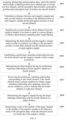
- when an obstacle exists in both the perception result and the labeling result, it is considered that the perception is correct, which is recorded as TP;
- when an obstacle appears in the labeled data, but does not appear in the perception result, it is considered that the perception system has missed detection, which is recorded as FN; and
- when an obstacle appears in the perception output, but does not appear in the labeled data, it is considered that the perception system has a misdetection, which is recorded as FP.
-
- when the TP is large enough, the number of FP has little influence on the indicator, and the indicator change is not sensitive and cannot directly reflect the recognition of the negative sample;
- the FP in the calculation formula contains not only the obstacle related to the negative sample, but also a large number of other virtual obstacles, for example, an obstacle is detected to be divided, or a new virtual obstacle is generated due to the defect of an algorithm;
- the information of the negative sample in the labeled data is not used in the calculation formula, and the information of the labeled negative sample is not involved in the matching and the calculation of the formula.
D=((x pt −x gt)2+(y pt −y gt)2+(z pt −z gt)2)1/2 Formula III
{right arrow over ((P 1 Q 1))},{right arrow over ((P 1 Q 2))},{right arrow over ((P 3 Q 2))},{right arrow over ((P 4 Q 4))},{right arrow over ((P n Q 4))}.
-
- the category of the obstacle is detected as a category of a physical obstacle, e.g., a vehicle, a person, a roadblock, etc., where the category of the physical obstacle may be selected and expanded according to actual needs, which is not particularly limited in the embodiment;
- the life cycle of the obstacle is greater than 10 frames, that is, the number of the image frames corresponding to the obstacle is greater than a preset number; in the current example, for example, the preset number may be 10; in the actual implementation process, the specific implementation of the preset number may be selected according to actual needs, which is not particularly limited in the embodiment;
- the length, width and height attributes of the obstacle throughout its entire life cycle are extracted, average values
L ,W ,H are calculated, and it is determined whether the change rate of the length, width and height (L, W, H) of the obstacle with respect to the average value at this time is greater than a given threshold; if yes, it means that the shape of the obstacle has undergone an abrupt change at this time, indicating that the shape of the obstacle is unstable, and the corresponding relationship should be retained at this time; otherwise, it means that the shape of the obstacle is relatively stable, and it is not a virtual obstacle caused by water mist, dust, etc., and the corresponding relationship should be removed.
{right arrow over ((P 3 Q 2))},{right arrow over ((P 4 Q 4))},{right arrow over ((P n Q 4))}.
-
- first is the input part of the detection system, which can obtain the labeled data and the perception data output by the perception system. For the labeled data, it can be divided into the positive sample and the negative sample based on whether the obstacle needs to be reported by the perception system. Where the positive sample is the obstacle that needs to be reported by the perception system, and the negative sample is the obstacle that does not need to be reported by the perception system.
-
- a calculation unit, configured to calculate a distance between each negative sample and each second obstacle, according to the labeled position of each negative sample and the perception position of each second obstacle; and
- a filtering unit, configured to retain the second obstacle whose distance from the negative sample is less than or equal to a preset distance to obtain the third obstacle remaining after the rough filtering.
-
- a determining unit, configured to determine the third obstacle and the negative sample which overlap in positions, according to the perception position of each third obstacle and the labeled position of each negative sample; and
- an establishment unit, configured to establish a preliminary matching relationship between the third obstacle and the negative sample which overlap in positions;
- where the establishment unit is further configured to determine a target matching relationship, according to the preliminary matching relationship and the third obstacle.
-
- the determining unit, further configured to determine the third obstacle having the preliminary matching relationship with the negative sample as a fourth obstacle; and
- an updating unit, configured to remove the preliminary matching relationship corresponding to the fourth obstacle if the fourth obstacle meets a preset condition to obtain the target matching relationship after updating, where the preset condition is used to indicate that the fourth obstacle is a physical obstacle.
-
- the determining unit, further configured to determine the negative sample having the target matching relationship with the fourth obstacle as the target obstacle.
-
- the determining unit, further configured to determine a ratio of the number of the target obstacle to the number of the negative sample as a detection result of the perception data, where the detection result is a recall rate of the negative sample.
Claims (13)
Applications Claiming Priority (2)
| Application Number | Priority Date | Filing Date | Title |
|---|---|---|---|
| CN202011552344.5A CN112541475B (en) | 2020-12-24 | 2020-12-24 | Perceptual data detection method and device |
| CN202011552344.5 | 2020-12-24 |
Publications (2)
| Publication Number | Publication Date |
|---|---|
| US20210406564A1 US20210406564A1 (en) | 2021-12-30 |
| US11869247B2 true US11869247B2 (en) | 2024-01-09 |
Family
ID=75017312
Family Applications (1)
| Application Number | Title | Priority Date | Filing Date |
|---|---|---|---|
| US17/471,022 Active 2042-01-27 US11869247B2 (en) | 2020-12-24 | 2021-09-09 | Perception data detection method and apparatus |
Country Status (5)
| Country | Link |
|---|---|
| US (1) | US11869247B2 (en) |
| EP (1) | EP3907659A3 (en) |
| JP (1) | JP2022024118A (en) |
| KR (1) | KR20210122214A (en) |
| CN (1) | CN112541475B (en) |
Families Citing this family (8)
| Publication number | Priority date | Publication date | Assignee | Title |
|---|---|---|---|---|
| JP7660390B2 (en) * | 2021-02-17 | 2025-04-11 | 株式会社小松製作所 | Unmanned vehicle management system and unmanned vehicle management method |
| CN112801225B (en) * | 2021-04-01 | 2021-06-18 | 中国人民解放军国防科技大学 | Automatic driving multi-sensor fusion sensing method and system under limit working condition |
| CN114092916B (en) * | 2021-11-26 | 2023-07-18 | 阿波罗智联(北京)科技有限公司 | Image processing method, device, electronic equipment, automatic driving vehicle and medium |
| CN114596706B (en) * | 2022-03-15 | 2024-05-03 | 阿波罗智联(北京)科技有限公司 | Detection method and device of road side perception system, electronic equipment and road side equipment |
| CN114840750B (en) * | 2022-04-26 | 2024-11-19 | 北京金堤科技有限公司 | Model construction method, relationship determination method, device, medium and equipment |
| CN116588137B (en) * | 2023-05-16 | 2025-12-05 | 中国第一汽车股份有限公司 | Methods, devices, media, and electronic equipment for detecting false perception of obstacles. |
| CN116778720B (en) * | 2023-08-25 | 2023-11-24 | 中汽传媒(天津)有限公司 | Traffic condition scene library construction and application method, system and electronic equipment |
| CN117216682B (en) * | 2023-09-27 | 2026-02-13 | 中国第一汽车股份有限公司 | A method, apparatus, electronic device, and storage medium for processing sensing data. |
Citations (31)
| Publication number | Priority date | Publication date | Assignee | Title |
|---|---|---|---|---|
| US20120002052A1 (en) * | 2010-03-02 | 2012-01-05 | Panasonic Corporation | Obstacle detection apparatus, obstacle detection system having same, and obstacle detection method |
| US20140266803A1 (en) * | 2013-03-15 | 2014-09-18 | Xerox Corporation | Two-dimensional and three-dimensional sliding window-based methods and systems for detecting vehicles |
| WO2015146113A1 (en) | 2014-03-28 | 2015-10-01 | 日本電気株式会社 | Identification dictionary learning system, identification dictionary learning method, and recording medium |
| JP2015232805A (en) | 2014-06-10 | 2015-12-24 | 株式会社豊田自動織機 | Image processing method, image processing apparatus, and image processing program |
| US20160167226A1 (en) * | 2014-12-16 | 2016-06-16 | Irobot Corporation | Systems and Methods for Capturing Images and Annotating the Captured Images with Information |
| JP2016173615A (en) | 2013-06-24 | 2016-09-29 | 株式会社日立ハイテクノロジーズ | Measurement system |
| CN106707293A (en) | 2016-12-01 | 2017-05-24 | 百度在线网络技术(北京)有限公司 | Obstacle recognition method and device for vehicles |
| JP2018013886A (en) | 2016-07-19 | 2018-01-25 | 日本電信電話株式会社 | Recognition easiness index calculation device, method, and program |
| JP2018036241A (en) | 2016-04-15 | 2018-03-08 | Jeインターナショナル株式会社 | Inspection method, inspection apparatus, inspection program, and recording medium |
| US9934689B2 (en) | 2014-12-17 | 2018-04-03 | Toyota Motor Engineering & Manufacturing North America, Inc. | Autonomous vehicle operation at blind intersections |
| CN108629231A (en) | 2017-03-16 | 2018-10-09 | 百度在线网络技术(北京)有限公司 | Obstacle detection method, device, equipment and storage medium |
| US20190080203A1 (en) * | 2017-09-11 | 2019-03-14 | Baidu Online Network Technology (Beijing) Co, Ltd | Method And Apparatus For Outputting Information |
| CN110069408A (en) | 2019-04-11 | 2019-07-30 | 杭州飞步科技有限公司 | Automatic driving vehicle sensory perceptual system test method and device |
| KR20190103503A (en) | 2018-02-12 | 2019-09-05 | 한양대학교 에리카산학협력단 | Apparatus and method for detecting lane |
| CN110287832A (en) | 2019-06-13 | 2019-09-27 | 北京百度网讯科技有限公司 | Obstacle perception evaluation method and device in high-speed automatic driving scene |
| JP2019175282A (en) | 2018-03-29 | 2019-10-10 | セコム株式会社 | Collation apparatus and collation method |
| US20200104612A1 (en) | 2018-09-27 | 2020-04-02 | Baidu Online Network Technology (Beijing) Co., Ltd. | Method and apparatus for detecting obstacle, electronic device, vehicle and storage medium |
| JP2020091543A (en) | 2018-12-03 | 2020-06-11 | キヤノン株式会社 | Learning device, processing device, neural network, learning method, and program |
| CN111291697A (en) | 2020-02-19 | 2020-06-16 | 北京百度网讯科技有限公司 | Method and apparatus for identifying obstacles |
| US20200257922A1 (en) * | 2019-02-12 | 2020-08-13 | Beijing Baidu Netcom Science And Technology Co., Ltd. | Method, apparatus, device and readable storage medium for image-based data processing |
| CN111753765A (en) | 2020-06-29 | 2020-10-09 | 北京百度网讯科技有限公司 | Detection method, device, device and storage medium for sensing device |
| US20200380274A1 (en) * | 2019-06-03 | 2020-12-03 | Nvidia Corporation | Multi-object tracking using correlation filters in video analytics applications |
| US20210012165A1 (en) * | 2018-03-29 | 2021-01-14 | Shanghai Zttvision Technologies Co.Ltd | Data processing method and device based on multi-sensor fusion, and multi-sensor fusion method |
| US20210133466A1 (en) * | 2019-10-31 | 2021-05-06 | Zoox, Inc. | State machine for obstacle avoidance |
| US20210398294A1 (en) * | 2019-05-27 | 2021-12-23 | Tencent Technology (Shenzhen) Company Limited | Video target tracking method and apparatus, computer device, and storage medium |
| US20220063604A1 (en) * | 2020-08-25 | 2022-03-03 | Subaru Corporation | Vehicle travel control device |
| US20220083787A1 (en) * | 2020-09-15 | 2022-03-17 | Beijing Baidu Netcom Science And Technology Co., Ltd. | Obstacle three-dimensional position acquisition method and apparatus for roadside computing device |
| US11321911B2 (en) * | 2017-10-11 | 2022-05-03 | Robert Bosch Gmbh | Method for representing the surroundings of a vehicle |
| US20220227385A1 (en) * | 2019-10-11 | 2022-07-21 | Denso Corporation | Driving assistance device for vehicle and driving assistance method for vehicle |
| US20220332348A1 (en) * | 2019-12-31 | 2022-10-20 | Huawei Technologies Co., Ltd. | Autonomous driving method, related device, and computer-readable storage medium |
| US20220371602A1 (en) * | 2020-01-14 | 2022-11-24 | Huawei Technologies Co., Ltd. | Vehicle positioning method, apparatus, and controller, intelligent vehicle, and system |
-
2020
- 2020-12-24 CN CN202011552344.5A patent/CN112541475B/en active Active
-
2021
- 2021-09-08 EP EP21195467.2A patent/EP3907659A3/en not_active Ceased
- 2021-09-09 US US17/471,022 patent/US11869247B2/en active Active
- 2021-09-16 KR KR1020210123843A patent/KR20210122214A/en not_active Abandoned
- 2021-11-19 JP JP2021188704A patent/JP2022024118A/en active Pending
Patent Citations (31)
| Publication number | Priority date | Publication date | Assignee | Title |
|---|---|---|---|---|
| US20120002052A1 (en) * | 2010-03-02 | 2012-01-05 | Panasonic Corporation | Obstacle detection apparatus, obstacle detection system having same, and obstacle detection method |
| US20140266803A1 (en) * | 2013-03-15 | 2014-09-18 | Xerox Corporation | Two-dimensional and three-dimensional sliding window-based methods and systems for detecting vehicles |
| JP2016173615A (en) | 2013-06-24 | 2016-09-29 | 株式会社日立ハイテクノロジーズ | Measurement system |
| WO2015146113A1 (en) | 2014-03-28 | 2015-10-01 | 日本電気株式会社 | Identification dictionary learning system, identification dictionary learning method, and recording medium |
| JP2015232805A (en) | 2014-06-10 | 2015-12-24 | 株式会社豊田自動織機 | Image processing method, image processing apparatus, and image processing program |
| US20160167226A1 (en) * | 2014-12-16 | 2016-06-16 | Irobot Corporation | Systems and Methods for Capturing Images and Annotating the Captured Images with Information |
| US9934689B2 (en) | 2014-12-17 | 2018-04-03 | Toyota Motor Engineering & Manufacturing North America, Inc. | Autonomous vehicle operation at blind intersections |
| JP2018036241A (en) | 2016-04-15 | 2018-03-08 | Jeインターナショナル株式会社 | Inspection method, inspection apparatus, inspection program, and recording medium |
| JP2018013886A (en) | 2016-07-19 | 2018-01-25 | 日本電信電話株式会社 | Recognition easiness index calculation device, method, and program |
| CN106707293A (en) | 2016-12-01 | 2017-05-24 | 百度在线网络技术(北京)有限公司 | Obstacle recognition method and device for vehicles |
| CN108629231A (en) | 2017-03-16 | 2018-10-09 | 百度在线网络技术(北京)有限公司 | Obstacle detection method, device, equipment and storage medium |
| US20190080203A1 (en) * | 2017-09-11 | 2019-03-14 | Baidu Online Network Technology (Beijing) Co, Ltd | Method And Apparatus For Outputting Information |
| US11321911B2 (en) * | 2017-10-11 | 2022-05-03 | Robert Bosch Gmbh | Method for representing the surroundings of a vehicle |
| KR20190103503A (en) | 2018-02-12 | 2019-09-05 | 한양대학교 에리카산학협력단 | Apparatus and method for detecting lane |
| JP2019175282A (en) | 2018-03-29 | 2019-10-10 | セコム株式会社 | Collation apparatus and collation method |
| US20210012165A1 (en) * | 2018-03-29 | 2021-01-14 | Shanghai Zttvision Technologies Co.Ltd | Data processing method and device based on multi-sensor fusion, and multi-sensor fusion method |
| US20200104612A1 (en) | 2018-09-27 | 2020-04-02 | Baidu Online Network Technology (Beijing) Co., Ltd. | Method and apparatus for detecting obstacle, electronic device, vehicle and storage medium |
| JP2020091543A (en) | 2018-12-03 | 2020-06-11 | キヤノン株式会社 | Learning device, processing device, neural network, learning method, and program |
| US20200257922A1 (en) * | 2019-02-12 | 2020-08-13 | Beijing Baidu Netcom Science And Technology Co., Ltd. | Method, apparatus, device and readable storage medium for image-based data processing |
| CN110069408A (en) | 2019-04-11 | 2019-07-30 | 杭州飞步科技有限公司 | Automatic driving vehicle sensory perceptual system test method and device |
| US20210398294A1 (en) * | 2019-05-27 | 2021-12-23 | Tencent Technology (Shenzhen) Company Limited | Video target tracking method and apparatus, computer device, and storage medium |
| US20200380274A1 (en) * | 2019-06-03 | 2020-12-03 | Nvidia Corporation | Multi-object tracking using correlation filters in video analytics applications |
| CN110287832A (en) | 2019-06-13 | 2019-09-27 | 北京百度网讯科技有限公司 | Obstacle perception evaluation method and device in high-speed automatic driving scene |
| US20220227385A1 (en) * | 2019-10-11 | 2022-07-21 | Denso Corporation | Driving assistance device for vehicle and driving assistance method for vehicle |
| US20210133466A1 (en) * | 2019-10-31 | 2021-05-06 | Zoox, Inc. | State machine for obstacle avoidance |
| US20220332348A1 (en) * | 2019-12-31 | 2022-10-20 | Huawei Technologies Co., Ltd. | Autonomous driving method, related device, and computer-readable storage medium |
| US20220371602A1 (en) * | 2020-01-14 | 2022-11-24 | Huawei Technologies Co., Ltd. | Vehicle positioning method, apparatus, and controller, intelligent vehicle, and system |
| CN111291697A (en) | 2020-02-19 | 2020-06-16 | 北京百度网讯科技有限公司 | Method and apparatus for identifying obstacles |
| CN111753765A (en) | 2020-06-29 | 2020-10-09 | 北京百度网讯科技有限公司 | Detection method, device, device and storage medium for sensing device |
| US20220063604A1 (en) * | 2020-08-25 | 2022-03-03 | Subaru Corporation | Vehicle travel control device |
| US20220083787A1 (en) * | 2020-09-15 | 2022-03-17 | Beijing Baidu Netcom Science And Technology Co., Ltd. | Obstacle three-dimensional position acquisition method and apparatus for roadside computing device |
Non-Patent Citations (10)
| Title |
|---|
| Extended European Search Report of EP21195467.2. |
| First Office Action of the parallel application JP 2021-188704. |
| First Office Action of the parallel application KR10-2021-0123843. |
| First Office Action of the priority application CN202011552344.5. |
| NPL1: "Automatic detection of road signs to support the creation of high-freshness navigation", DOI : https://doi.org/10.11371/iieej.36.456, Journal of the Institute of Image Electronics Engineers of Japan, Japan, Institute of Image Electronics Engineers of Japan, Jul. 25, 2007, vol. 36, No. 4, pp. 456-464. |
| NPL1: "Towards a Real Time Obstacle Detection System for Unmanned Surface Vehicles", Oceans 2019 MTS/IEEE Seattle, Marine Technology Society, pp. 1-8, XP033691202. |
| NPL2: "Obstacle Detection for Image-Guided Surface Water Navigation", 2016 13th Conference on Computer and Robot Vision (CRV), pp. 45-52, XP033032995. |
| NPL3: "Obstacles and Foliage Discrimination Using Lidar", Proceeding of SPIE, ISSN 0277-786X vol. 10524, SPIE US, vol. 9837, May 13, 2016, pp. 98370E-98370E, XP060070300. |
| NPL4: "Energy Minimization Approach for Negative Obstacle Region Detection", IEEE Transaction on Vehicular Technology, IEEE, USA, vol. 68, No. 12 pp. 11668-11678, XP011762211. |
| NPL5: "PVS: A system for large scale outdoor perception performance evaluation", Robotics and Automation (ICRA), 2011 IEEE International Conference on May 9, 2011, pp. 834-841, XP032034239. |
Also Published As
| Publication number | Publication date |
|---|---|
| JP2022024118A (en) | 2022-02-08 |
| EP3907659A2 (en) | 2021-11-10 |
| CN112541475B (en) | 2024-01-19 |
| EP3907659A3 (en) | 2022-04-06 |
| CN112541475A (en) | 2021-03-23 |
| US20210406564A1 (en) | 2021-12-30 |
| KR20210122214A (en) | 2021-10-08 |
Similar Documents
| Publication | Publication Date | Title |
|---|---|---|
| US11869247B2 (en) | Perception data detection method and apparatus | |
| US20230099113A1 (en) | Training method and apparatus for a target detection model, target detection method and apparatus, and medium | |
| US12263834B2 (en) | Spatial parking place detection method and device, storage medium, and program product | |
| US12131598B2 (en) | Testing method and apparatus for vehicle perception system, device, and storage medium | |
| CN112764013B (en) | Automatic driving vehicle perception system testing methods, devices, equipment and storage media | |
| CN112966599B (en) | Training method of key point recognition model, key point recognition method and device | |
| CN112559371B (en) | Automatic driving test method and device and electronic equipment | |
| CN114581890B (en) | Method and device for determining lane line, electronic equipment and storage medium | |
| CN114495034B (en) | Method, device, equipment and storage medium for visualizing target detection effect | |
| EP4080479A2 (en) | Method for identifying traffic light, device, cloud control platform and vehicle-road coordination system | |
| CN113392794B (en) | Vehicle cross-line identification method, device, electronic device and storage medium | |
| CN113538963A (en) | Method, apparatus, device and storage medium for outputting information | |
| CN113722342A (en) | High-precision map element change detection method, device and equipment and automatic driving vehicle | |
| CN115984789B (en) | Lane detection method, device, equipment and storage medium | |
| CN115953759A (en) | Detection method, device, electronic equipment and storage medium for parking space limiter | |
| CN114155508A (en) | Road change detection method, device, equipment and storage medium | |
| WO2025251501A1 (en) | Lane traffic cone recognition method and apparatus for vehicle, electronic device and storage medium | |
| CN117690133A (en) | Point cloud data labeling method and device, electronic equipment, vehicle and medium | |
| CN116311149A (en) | Obstacle filtering method, device and storage medium | |
| CN114241442A (en) | Method, apparatus and computer program product for determining an identification index | |
| CN115810270A (en) | Method, device, electronic device and storage medium for vehicle steering detection | |
| CN116052113A (en) | Point cloud data processing method, device, smart chip, storage medium and vehicle | |
| CN114625823A (en) | Lane line data processing method, device, equipment and storage medium | |
| CN113807236A (en) | Method, apparatus, device, storage medium and program product for lane line detection | |
| US12430871B2 (en) | Object association method and apparatus and electronic device |
Legal Events
| Date | Code | Title | Description |
|---|---|---|---|
| FEPP | Fee payment procedure |
Free format text: ENTITY STATUS SET TO UNDISCOUNTED (ORIGINAL EVENT CODE: BIG.); ENTITY STATUS OF PATENT OWNER: LARGE ENTITY |
|
| STPP | Information on status: patent application and granting procedure in general |
Free format text: DOCKETED NEW CASE - READY FOR EXAMINATION |
|
| AS | Assignment |
Owner name: APOLLO INTELLIGENT CONNECTIVITY (BEIJING) TECHNOLOGY CO., LTD., CHINA Free format text: ASSIGNMENT OF ASSIGNORS INTEREST;ASSIGNORS:LI, DAN;LI, JIANPING;CHEN, QIAN;REEL/FRAME:058748/0847 Effective date: 20211225 |
|
| STPP | Information on status: patent application and granting procedure in general |
Free format text: NON FINAL ACTION MAILED |
|
| STPP | Information on status: patent application and granting procedure in general |
Free format text: RESPONSE TO NON-FINAL OFFICE ACTION ENTERED AND FORWARDED TO EXAMINER |
|
| STPP | Information on status: patent application and granting procedure in general |
Free format text: NOTICE OF ALLOWANCE MAILED -- APPLICATION RECEIVED IN OFFICE OF PUBLICATIONS |
|
| STPP | Information on status: patent application and granting procedure in general |
Free format text: AWAITING TC RESP., ISSUE FEE NOT PAID |
|
| STPP | Information on status: patent application and granting procedure in general |
Free format text: AWAITING TC RESP, ISSUE FEE PAYMENT RECEIVED |
|
| STPP | Information on status: patent application and granting procedure in general |
Free format text: PUBLICATIONS -- ISSUE FEE PAYMENT VERIFIED |
|
| STCF | Information on status: patent grant |
Free format text: PATENTED CASE |