US11862833B2 - Coupling assembly including a first waveguide with a first end and second waveguide with a second end, where a locking mechanism connects the first end to the second end - Google Patents
Coupling assembly including a first waveguide with a first end and second waveguide with a second end, where a locking mechanism connects the first end to the second end Download PDFInfo
- Publication number
- US11862833B2 US11862833B2 US17/324,901 US202117324901A US11862833B2 US 11862833 B2 US11862833 B2 US 11862833B2 US 202117324901 A US202117324901 A US 202117324901A US 11862833 B2 US11862833 B2 US 11862833B2
- Authority
- US
- United States
- Prior art keywords
- waveguide
- coupling assembly
- locking mechanism
- locking portion
- locking
- Prior art date
- Legal status (The legal status is an assumption and is not a legal conclusion. Google has not performed a legal analysis and makes no representation as to the accuracy of the status listed.)
- Active, expires
Links
- 230000008878 coupling Effects 0.000 title claims abstract description 231
- 238000010168 coupling process Methods 0.000 title claims abstract description 231
- 238000005859 coupling reaction Methods 0.000 title claims abstract description 231
- 230000007246 mechanism Effects 0.000 title claims description 65
- 125000006850 spacer group Chemical group 0.000 claims description 70
- 238000003780 insertion Methods 0.000 claims description 6
- 230000037431 insertion Effects 0.000 claims description 6
- 238000000034 method Methods 0.000 claims 1
- 238000009434 installation Methods 0.000 abstract description 6
- 238000004519 manufacturing process Methods 0.000 abstract description 6
- 230000000712 assembly Effects 0.000 description 12
- 238000000429 assembly Methods 0.000 description 12
- 230000007423 decrease Effects 0.000 description 4
- 239000000463 material Substances 0.000 description 2
- 230000010287 polarization Effects 0.000 description 2
- 230000004075 alteration Effects 0.000 description 1
- 238000006243 chemical reaction Methods 0.000 description 1
- 238000012986 modification Methods 0.000 description 1
- 230000004048 modification Effects 0.000 description 1
- 239000003607 modifier Substances 0.000 description 1
- 230000003287 optical effect Effects 0.000 description 1
- 230000000284 resting effect Effects 0.000 description 1
Images


Classifications
-
- H—ELECTRICITY
- H01—ELECTRIC ELEMENTS
- H01P—WAVEGUIDES; RESONATORS, LINES, OR OTHER DEVICES OF THE WAVEGUIDE TYPE
- H01P1/00—Auxiliary devices
- H01P1/04—Fixed joints
- H01P1/042—Hollow waveguide joints
-
- H—ELECTRICITY
- H01—ELECTRIC ELEMENTS
- H01P—WAVEGUIDES; RESONATORS, LINES, OR OTHER DEVICES OF THE WAVEGUIDE TYPE
- H01P3/00—Waveguides; Transmission lines of the waveguide type
- H01P3/12—Hollow waveguides
-
- H—ELECTRICITY
- H01—ELECTRIC ELEMENTS
- H01P—WAVEGUIDES; RESONATORS, LINES, OR OTHER DEVICES OF THE WAVEGUIDE TYPE
- H01P5/00—Coupling devices of the waveguide type
- H01P5/02—Coupling devices of the waveguide type with invariable factor of coupling
-
- H—ELECTRICITY
- H01—ELECTRIC ELEMENTS
- H01P—WAVEGUIDES; RESONATORS, LINES, OR OTHER DEVICES OF THE WAVEGUIDE TYPE
- H01P5/00—Coupling devices of the waveguide type
- H01P5/02—Coupling devices of the waveguide type with invariable factor of coupling
- H01P5/022—Transitions between lines of the same kind and shape, but with different dimensions
- H01P5/024—Transitions between lines of the same kind and shape, but with different dimensions between hollow waveguides
Definitions
- the present disclosure generally relates to coupling assemblies.
- the present disclosure relates to coupling assemblies that are configured to form a quick, preferably mechanical and electromagnetic, connection between two devices. More particularly, the coupling assemblies of the present disclosure are suited for use in connecting devices in the form of a radio and an antenna to one another.
- Conventional coupling assemblies can connect two devices to one another in mechanical, optical, fluidic, electric, electromagnetic or other manners.
- With regards to connecting two devices together such as radios and antennas, these aforementioned issues raise manufacturing costs and increase the difficulty of field installations when radios and antennas must be connected via waveguide interfaces that have varying dimensions and different waveguide shapes.
- the present disclosure efficiently addresses the aforementioned problems and solves the issues and/or improves conventional coupling assemblies.
- the present disclosure provides for a quick coupling assembly having a fixed or single size for a wide range of dimensions of devices to be connected and disconnected in combination with mechanical and electromagnetic connection means, such as connecting a radio to an antenna via waveguide interface.
- mechanical and electromagnetic connection means such as connecting a radio to an antenna via waveguide interface.
- Each radio and antenna pair can operate in a particular frequency band, each requiring or having different waveguide dimensions suitable for that particular frequency band.
- the present quick coupling assembly can accommodate these various waveguides having different shapes and sizes as the coupling assembly shares a fixed or single sized quick coupling interface or locking mechanism.
- the present coupling assembly is designed to allow connections and disconnections by easy and quick means, without the need for specific tools, by using bare hands, and allows connections and disconnections of varying devices such as radios and antennas to be performed in restricted conditions such as field installations.
- the present coupling assembly thereby increases the efficiency of these field installations and solves various manufacturing problems and reduces costs.
- FIG. 1 is a perspective view of an embodiment of the coupling assembly having a circular waveguide.
- FIG. 2 is a front view and side cross sectional view of the coupling assembly as shown in FIG. 1 .
- FIG. 3 is a perspective view of an embodiment of the coupling assembly having a circular waveguide with a smaller diameter than the embodiment of FIG. 1 .
- FIG. 4 is a perspective view of an embodiment of the coupling assembly having a circular waveguide with a smaller diameter than the embodiment of FIG. 3 .
- FIG. 5 is a perspective view of an embodiment of the coupling assembly having a square waveguide.
- FIG. 6 is a perspective view of an embodiment of the coupling assembly having a square waveguide with a smaller perimeter than the embodiment of FIG. 5 .
- FIG. 7 A is a top cross-sectional view of an embodiment of a coupling assembly having a circular waveguide.
- FIG. 7 B is a top cross-sectional view of an embodiment of a coupling assembly having a circular waveguide with a smaller diameter than the embodiment of FIG. 7 A with a spacer.
- FIG. 7 C is a top cross-sectional view of an embodiment of a coupling assembly having a circular waveguide with a smaller diameter than the embodiment of FIG. 7 B with a larger spacer.
- FIG. 7 D is a perspective view of the embodiment of FIG. 7 A .
- FIG. 7 E is a perspective view of the embodiment of FIG. 7 B .
- FIG. 7 F is a perspective view of the embodiment of FIG. 7 C .
- FIG. 8 A is a top cross-sectional view of an embodiment of a coupling assembly having a circular waveguide.
- FIG. 8 C is a top cross-sectional view of an embodiment of a coupling assembly having a circular waveguide with a smaller diameter than the embodiment of FIG. 8 B with a larger integrated spacer.
- FIG. 8 D is a perspective view of the embodiment of FIG. 8 A .
- FIG. 8 E is a perspective view of the embodiment of FIG. 8 B .
- FIG. 8 F is a perspective view of the embodiment of FIG. 8 C .
- FIG. 9 A is a top cross-sectional view of an embodiment of a coupling assembly having a circular waveguide, with different inner diameters.
- FIG. 9 B is a top cross-sectional view of an embodiment of a coupling assembly having a circular waveguide with a smaller inner diameter than the embodiment of FIG. 9 A with different inner diameters and a spacer.
- FIG. 9 F is a perspective view of the embodiment of FIG. 9 C .
- FIG. 10 A is a top cross-sectional view of an embodiment of a coupling assembly having a circular waveguide, with different inner diameters.
- FIG. 10 B is a top cross-sectional view of an embodiment of a coupling assembly having a circular waveguide with a smaller inner diameter than the embodiment of FIG. 10 A with different inner diameters and an integrated spacer.
- FIG. 10 C is a top cross-sectional view of an embodiment of a coupling assembly having a circular waveguide with a smaller inner diameter than the embodiment of FIG. 10 B with different inner diameters and a larger integrated spacer.
- FIG. 10 D is a perspective view of the embodiment of FIG. 10 A .
- FIG. 10 E is a perspective view of the embodiment of FIG. 10 B .
- FIG. 10 F is a perspective view of the embodiment of FIG. 10 C .
- FIG. 11 A is a top cross-sectional view of an embodiment of a touch contact coupling assembly having a circular waveguide.
- FIG. 11 B is a top cross-sectional view of an embodiment of a touch contact coupling assembly having a circular waveguide with a smaller diameter than the embodiment of FIG. 11 A with a spacer.
- FIG. 11 C is a top cross-sectional view of an embodiment of a touch contact coupling assembly having a circular waveguide with a smaller diameter than the embodiment of FIG. 11 B with a larger spacer.
- FIG. 11 D is a perspective view of the embodiment of FIG. 11 A .
- FIG. 11 F is a perspective view of the embodiment of FIG. 11 C .
- FIG. 12 A is a top cross-sectional view of an embodiment of a touch contact coupling assembly having a circular waveguide.
- FIG. 12 C is a top cross-sectional view of an embodiment of a touch contact coupling assembly having a circular waveguide with a smaller diameter than the embodiment of FIG. 12 B with a larger integrated spacer.
- FIG. 12 D is a perspective view of the embodiment of FIG. 12 A .
- FIG. 12 E is a perspective view of the embodiment of FIG. 12 B .
- FIG. 12 F is a perspective view of the embodiment of FIG. 12 C .
- FIG. 13 A is a perspective cross-sectional view of a touch contact type coupling assembly.
- FIG. 13 B is a perspective cross-sectional view of an insertion type coupling assembly.
- FIG. 13 C is a perspective cross-sectional view of a diameter offset coupling assembly.
- FIG. 15 A is a perspective cross-sectional view of a circular waveguide in contact with a spacer.
- FIG. 15 B is a perspective cross-sectional view of a circular waveguide with a smaller diameter than the embodiment of FIG. 15 A in contact with a larger spacer.
- FIG. 16 A is a top view and side cross sectional view of the spacer as shown in FIG. 15 A .
- FIG. 16 B is a top view and side cross sectional view of the spacer as shown in FIG. 15 B .
- FIG. 17 A is a perspective cross-sectional view of a circular waveguide with an integrated spacer.
- FIG. 17 B is a perspective cross-sectional view of a circular waveguide with a smaller diameter than the embodiment of FIG. 17 A with a larger integrated spacer.
- FIG. 18 is a top perspective view of wave guides of different shapes and sizes that can be coupled together with a locking mechanism.
- FIG. 19 provides side perspective views of different locking mechanism coupling types.
- FIG. 20 A is a side perspective view of an embodiment of a twist type locking coupling.
- FIG. 20 B is a opposite perspective view of the embodiment of the twist type locking coupling shown in FIG. 20 A .
- FIG. 21 A is a top partial cross-sectional view of the coupling of FIG. 20 A , and side cross-sectional views of the couplings prior to connection.
- FIG. 21 B is a top partial cross-sectional view of the coupling of FIG. 20 A , and side cross-sectional views of the coupling during connection of the couplings and prior to twisting the couplings.
- FIG. 21 D is a top partial cross-sectional view of the coupling of FIG. 20 A , and side cross sectional views of the coupling during connection of the couplings after twisting of the couplings is completed and the couplings are locked together.
- FIG. 1 shows a perspective view of a coupling assembly 101 according to the present disclosure.
- Coupling assembly 101 has a first portion 10 that can be connected and disconnected via a bayonet locking mechanism by a user, easily by hand to a second portion 50 .
- First portion 10 has a first waveguide portion 15 that is joined to and/or connectable to a hollow cylindrical portion 20 .
- the first waveguide portion 15 of coupling assembly 101 is circular, so that the waveguide portion 15 is a hollow cylindrical tube.
- waveguide portion 15 has an outer diameter that is less than the outer diameter of hollow cylindrical portion 20 .
- first waveguide portion 15 provides a connection for a first device such as an antenna.
- cylindrical portion 20 has four protrusions 25 , for use in locking and unlocking first portion 10 and second portion 50 together.
- cylindrical portion 20 has at least one, or least two or at least four protrusions 25 .
- four protrusions are preferred, as this embodiment allows axial alignment of the antenna and radio in 90-degree steps reflecting Vertical and Horizontal polarization planes of the linear polarization of both electromagnetic waves radiating from the antenna and fields inside of the waveguides.
- Protrusions 25 are located on the outer edge of the circumference of the cylindrical portion 20 that is closest to the second portion 50 when the first and second portions are connected. Protrusions 25 extend outward from the cylindrical portion 20 in a perpendicular direction to the central axis of the coupling assembly 101 . If more than one protrusion 25 is present in a particular embodiment of the coupling assembly, then these protrusions are spaced equidistant from each other along the circumference of the cylindrical portion 20 . Cylindrical portion 20 , has a width 21 . Each protrusion 25 has a width 26 that is less than width 21 of Cylindrical portion 20 . Protrusion 25 is part of a first portion of a bayonet locking mechanism that works in conjunction with the second portion of the mechanism located on second portion 50 .
- Second portion 50 has a second waveguide portion 55 that is joined to and/or connectable to a hollow cylindrical portion 70 .
- the second waveguide portion 55 of coupling assembly 101 is circular, so that the waveguide portion 55 is a hollow cylindrical tube.
- waveguide portion 55 has an outer diameter that is less than the outer diameter of hollow cylindrical portion 70 .
- At the interface or point of connection between portion 55 and portion 70 there is a flat surface 56 that is perpendicular to the central axis of the coupling assembly 101 that extends through the center of the waveguide 55 .
- flat surface 56 has a varying surface area, that increases when the outer diameter of waveguide portion 55 decreases and decreases when the outer diameter of waveguide portion 55 increases.
- waveguide portion 55 , flat surface 56 and cylindrical portion 70 are a single unitary piece.
- second waveguide portion 55 provides a connection for a second device such as a radio.
- Second portion 50 has an inner cylindrical tube portion 80 that interconnects with the inner portion of hollow cylindrical portion 20 and the inner portion of first waveguide portion 15 , when the second portion 50 is connected via the bayonet locking mechanism to the first portion 10 .
- the inner diameter of the cylindrical tube portion 80 matches the inner diameter of the waveguide portion 15 .
- the inner diameter of the cylindrical tube portion 80 is less than the inner diameter of the first waveguide portion 15 .
- the embodiment of coupling assembly 102 is identical to the embodiment of coupling assembly 101 shown in FIGS. 1 - 2 , except that the waveguide 15 and tube portion 80 of embodiment 102 , each have outer and inner diameters that are smaller when compared to the outer and inner diameters of the corresponding waveguide 15 and tube portion 80 of embodiment 101 as shown in FIGS. 1 - 2 . Furthermore, the areas of flat surface 16 and 75 is greater in embodiment 102 as compared to corresponding areas of embodiment 101 , since the diameters of waveguide portion 15 and tube portion 80 is smaller, and since the outer diameters of the tube portions 20 and 70 remain the same as in embodiment 101 .
- the embodiment of coupling assembly 103 is identical to the embodiment of coupling assembly 102 shown in FIG. 3 , except that the waveguide 15 and tube portion 80 of embodiment 103 , each have outer and inner diameters that are smaller when compared to the outer and inner diameters of the corresponding waveguide 15 and tube portion 80 of embodiment 102 as shown. Furthermore, the areas of flat surface 16 and 75 is greater in embodiment 103 as compared to corresponding areas of embodiment 102 , since the diameters of waveguide portion 15 and tube portion 80 is smaller, and since the outer diameters of the tube portions 20 and 70 remain the same as in embodiment 102 and 101 .
- coupling assemblies 101 , 102 , and 103 have circular waveguides
- coupling assemblies 201 and 202 have square waveguides
- other waveguide shapes such as triangular, oblong and elliptical, or other waveguide shapes can be used along with the coupling assembly of the present disclosure.
- FIGS. 7 A- 7 F, 8 A- 8 F, 9 A- 9 F, 10 A- 10 F, 11 A- 11 F, and 12 A- 12 F as described below, refer to the embodiments 101 , 102 , and 103 as described above, and further describe additional information and alterations to the above embodiments such as but not limited to the use of spacers, casings, integrated spacers, and the use of different sized or varying inner diameters.
- cylindrical portion 70 is connected to an outer casing 90 .
- Outer casing 90 in some embodiments, can be a housing for a device such as a radio.
- Second waveguide portion 55 and inner tube portion 80 can be a unitary single piece that are connected to cylindrical portion 70 through a central circular hole in portion 70 .
- protrusion 57 At the boundary between the outer diameter of second waveguide 55 and the outer diameter of tube portion 80 , is protrusion 57 that is at the diameter of the second waveguide 55 .
- Protrusion 57 comes into contact with flat surface 56 , so as to prevent second waveguide portion 55 from passing through the central hole in portion 70 and keeps waveguide portion 55 within casing 90 as shown.
- the central hole in cylindrical portion 70 is at the same diameter size as the outer diameter of inner tube portion 80 .
- Coupling assembly 101 as shown in FIG. 7 A has a first waveguide portion 15 with an inner diameter 17 , that is the same as the inner diameter of inner tube portion 80 and second waveguide portion 55 .
- Recess 19 has a diameter that is equal to the outer diameter of inner tube portion 80 and can receive a portion of tube 80 .
- FIG. 7 B a top cross-sectional view of an embodiment of coupling assembly 102 is shown.
- cylindrical portion 70 is connected to an outer casing 90 .
- Outer casing 90 in some embodiments, can be a housing for a device such as a radio.
- Second waveguide portion 55 and inner tube portion 80 can be a unitary single piece that are connected to cylindrical portion 70 through a central circular hole in portion 70 .
- the inner diameter of the first wave guide 15 , inner tube portion 80 and second waveguide portion 55 have the same inner diameter 17 .
- the inner diameter 17 of coupling assembly 102 is smaller than the inner diameter 17 of coupling assembly 101 .
- the central hole in cylindrical portion 70 of coupling assembly 102 as shown in FIG. 7 B is the same size as the central hole portion 70 as shown in the coupling assembly 101 as shown in FIG. 7 A . Due to the difference in diameters of the hole in cylindrical portion 70 in coupling 102 and the outer diameter of tube portion 80 in coupling assembly 102 , a spacer 95 must be placed between the central hole in portion 70 and the outer portion of tube 80 , to keep tube 80 in place and keeps waveguide portion 55 within casing 90 as shown.
- Protrusion 57 comes into contact with spacer 95 , and spacer 95 comes into contact with flat surface 56 .
- spacer 95 bridges the gap between the hole and the diameter of tube 80 , while a portion of spacer 95 fits around second waveguide 55 and contacts surface 56 .
- Recess 19 of coupling assembly 102 has a diameter that is equal to the outer diameter of inner tube portion 80 of coupling assembly 102 so that the recess 19 can receive a portion of inner tube 80 .
- FIG. 7 C a top cross-sectional view of an embodiment of coupling assembly 103 is shown.
- cylindrical portion 70 is connected to an outer casing 90 .
- Outer casing 90 in some embodiments, can be a housing for a device such as a radio.
- Second waveguide portion 55 and inner tube portion 80 can be a unitary single piece that are connected to cylindrical portion 70 through a central hole in portion 70 .
- Coupling assembly 103 as shown in FIG. 7 C as a first waveguide portion 15 with an inner diameter 17 , that is the same as the inner diameter of inner tube portion 80 and second waveguide portion 55 .
- the inner diameter 17 of coupling assembly 103 is smaller than the inner diameter 17 of coupling assembly 102 .
- spacer 95 When spacer 95 is placed between the hole and tube 80 , spacer 95 bridges the gap between the hole and the diameter of tube 80 , while a portion of spacer 95 fits around second waveguide 55 and contacts surface 56 . Protrusion 57 comes into contact with spacer 95 , and spacer 95 comes into contact with flat surface 56 .
- Spacer 95 of coupling assembly 103 is greater in size than the spacer 95 of coupling assembly 102 .
- Recess 19 of coupling assembly 103 has a diameter that is equal to the outer diameter of inner tube portion 80 of coupling assembly 103 so that the recess 19 can receive a portion of inner tube 80 .
- FIG. 7 D a perspective view of the embodiment 101 of FIG. 7 A is shown.
- FIG. 7 E a perspective view of the embodiment 102 of FIG. 7 B is shown.
- FIG. 7 F a perspective view of the embodiment 103 of FIG. 7 C is shown.
- FIG. 8 B a top cross-sectional view of an embodiment of coupling assembly 102 is shown.
- cylindrical portion 70 is connected to an outer casing 90 .
- Outer casing 90 in some embodiments, can be a housing for a device such as a radio.
- the inner diameter of the first wave guide 15 , inner tube portion 80 and second waveguide portion 55 have the same inner diameter 17 .
- the inner diameter 17 of coupling assembly 102 is smaller than the inner diameter 17 of coupling assembly 101 of FIG. 8 A .
- an integrated spacer 96 is an integrated spacer 96 , or referred to as protrusion 96 .
- Protrusion 57 of FIG. 8 A is not present in the embodiments shown in FIGS. 8 B and 8 C .
- the central hole in cylindrical portion 70 of coupling assembly 102 as shown in FIG. 8 B is the same size as the central hole portion 70 as shown in the coupling assembly 101 as shown in FIG. 8 A .
- protrusion 96 increases the diameter, to keep tube 80 in place and keeps waveguide portion 55 within casing 90 as shown.
- Protrusion 96 comes into contact with flat surface 56 .
- Protrusion 96 is part of a single unitary piece that includes inner tube 80 , and second waveguide 55 .
- Recess 19 of coupling assembly 102 has a diameter that is equal to the outer diameter of inner tube portion 80 of coupling assembly 102 so that the recess 19 can receive a portion of inner tube 80 .
- FIG. 8 C a top cross-sectional view of an embodiment of coupling assembly 103 is shown.
- cylindrical portion 70 is connected to an outer casing 90 .
- Outer casing 90 in some embodiments, can be a housing for a device such as a radio.
- Coupling assembly 103 as shown in FIG. 8 C has a first waveguide portion 15 with an inner diameter 17 , that is the same as the inner diameter of inner tube portion 80 and second waveguide portion 55 .
- the inner diameter 17 of coupling assembly 103 as shown in FIG. 8 C is smaller than the inner diameter 17 of coupling assembly 102 as shown in FIG. 8 B .
- protrusion 96 At the boundary between the greater outer diameter of second waveguide 55 and the lesser outer diameter of tube portion 80 , is protrusion 96 .
- the central hole in cylindrical portion 70 of coupling assembly 103 as shown in FIG. 8 C is the same size as the coupling assembly 101 as shown in FIG. 8 A . Due to the difference in diameters of the hole in cylindrical portion 70 in coupling 103 and the outer diameter of tube portion 80 in coupling assembly 103 , protrusion 96 increases the diameter of tube 80 , to keep tube 80 in place and keeps waveguide portion 55 within casing 90 as shown. Protrusion 96 comes into contact with flat surface 56 . Protrusion 96 is part of a single unitary piece that includes inner tube 80 , and second waveguide 55 .
- Protrusion 96 of coupling assembly 103 is greater in size than the Protrusion 96 of coupling assembly 102 .
- Recess 19 of coupling assembly 103 has a diameter that is equal to the outer diameter of inner tube portion 80 of coupling assembly 103 so that the recess 19 can receive a portion of inner tube 80 .
- FIG. 8 D a perspective view of the embodiment 101 of FIG. 8 A is shown.
- FIG. 8 E a perspective view of the embodiment 102 of FIG. 8 B is shown.
- FIG. 8 F a perspective view of the embodiment 103 of FIG. 8 C is shown.
- cylindrical portion 70 is connected to an outer casing 90 .
- Outer casing 90 in some embodiments, can be a housing for a device such as a radio.
- Second waveguide portion 55 and inner tube portion 80 can be a unitary single piece that are connected to cylindrical portion 70 through a central circular hole in portion 70 .
- protrusion 57 At the boundary between the outer diameter of second waveguide 55 and the outer diameter of tube portion 80 , is protrusion 57 that is at the diameter of the second waveguide 55 .
- Protrusion 57 comes into contact with flat surface 56 , so as to prevent second waveguide portion 55 from passing through the central hole in portion 70 and keeps waveguide portion 55 within casing 90 as shown.
- the central hole in cylindrical portion 70 is at the same diameter size as the outer diameter of inner tube portion 80 .
- Coupling assembly 101 as shown in FIG. 9 A has a first waveguide portion 15 with an inner diameter 17 , that is larger than the inner diameter 81 of inner tube portion 80 .
- the inner diameter 81 of tube portion 80 is the same as the inner diameter of the second waveguide portion 55 .
- the embodiment of coupling assembly 101 as shown in FIG. 9 A does not have a recess 19 to receive a portion of tube 80 .
- the outer diameter of tube portion 80 is the same as the inner diameter 17 of first waveguide portion 15 .
- the coupling assembly 101 as shown in FIG. 9 A therefore has two varying inner diameters 17 and 81 .
- a varying inner diameter also referred to as an offset diameter can be useful for specific purposes such as impedance matching, and waveguide mode conversion and can be changed as needed for a particular antenna design.
- FIG. 9 B a top cross-sectional view of an embodiment of coupling assembly 102 is shown.
- cylindrical portion 70 is connected to an outer casing 90 .
- Outer casing 90 in some embodiments, can be a housing for a device such as a radio.
- Second waveguide portion 55 and inner tube portion 80 can be a unitary single piece that are connected to cylindrical portion 70 through a central hole in portion 70 .
- the inner diameter 17 of the first wave guide 15 is larger than the inner diameter 81 of tube portion 80 .
- Tube portion 80 and second waveguide portion 55 have the same inner diameter 81 .
- the inner diameter 17 of coupling assembly 102 as shown in FIG.
- Protrusion 57 comes into contact with spacer 95 , and spacer 95 comes into contact with flat surface 56 .
- spacer 95 bridges the gap between the hole and the diameter of tube 80 , while a portion of spacer 95 fits around second waveguide 55 and contacts surface 56 .
- the embodiment of coupling assembly 102 as shown in FIG. 9 B does not have a recess 19 to receive a portion of tube 80 .
- the outer diameter of tube portion 80 is the same as the inner diameter 17 of first waveguide portion 15 .
- the coupling assembly 102 as shown in FIG. 9 B therefore has two varying inner diameters 17 and 81 with diameter 17 being greater than diameter 81 .
- the inner diameter 17 and inner diameter 81 of coupling assembly 102 as shown in FIG. 9 B is smaller than the inner diameter 17 and inner diameter 81 of coupling assembly 101 as shown in FIG. 9 A .
- FIG. 9 C a top cross-sectional view of an embodiment of coupling assembly 103 is shown.
- cylindrical portion 70 is connected to an outer casing 90 .
- Outer casing 90 in some embodiments, can be a housing for a device such as a radio.
- Second waveguide portion 55 and inner tube portion 80 can be a unitary single piece that are connected to cylindrical portion 70 through a central hole in portion 70 .
- the inner diameter 17 of the first wave guide 15 is larger than the inner diameter 81 of tube portion 80 .
- Tube portion 80 and second waveguide portion 55 have the same inner diameter 81 .
- the inner diameter 17 of coupling assembly 102 as shown in FIG.
- FIG. 9 C is smaller than the inner diameter 17 of coupling assembly 101 as shown in FIG. 9 B .
- protrusion 57 that is at the diameter of the second waveguide 55 .
- the central hole in cylindrical portion 70 of coupling assembly 102 as shown in FIG. 9 C is the same size as the central hole portion 70 as shown in the coupling assembly 101 as shown in FIG. 9 A . Due to the difference in diameters of the hole in cylindrical portion 70 in coupling assembly 103 and the outer diameter of tube portion 80 in coupling assembly 103 , a spacer 95 must be placed between the central hole in portion 70 and the outer portion of tube 80 , to keep tube 80 in place and keeps waveguide portion 55 within casing 90 as shown.
- Protrusion 57 comes into contact with spacer 95 , and spacer 95 comes into contact with flat surface 56 .
- spacer 95 bridges the gap between the hole and the diameter of tube 80 , while a portion of spacer 95 fits around second waveguide 55 and contacts surface 56 .
- the embodiment of coupling assembly 103 as shown in FIG. 9 C does not have a recess 19 to receive a portion of tube 80 .
- the outer diameter of tube portion 80 is the same as the inner diameter 17 of first waveguide portion 15 .
- the coupling assembly 103 as shown in FIG. 9 C therefore has two varying inner diameters 17 and 81 with diameter 17 being greater than diameter 81 .
- the inner diameter 17 and inner diameter 81 of coupling assembly 103 as shown in FIG. 9 C is smaller than the inner diameter 17 and inner diameter 81 of coupling assembly 102 as shown in FIG. 9 B .
- Spacer 95 of coupling assembly 103 as shown in FIG. 9 C is greater in size than the spacer 95 of coupling assembly 102 as shown in FIG. 9 B .
- FIG. 9 D a perspective view of the embodiment 101 of FIG. 9 A is shown.
- FIG. 9 E a perspective view of the embodiment 102 of FIG. 9 B is shown.
- FIG. 9 F a perspective view of the embodiment 103 of FIG. 9 C is shown.
- FIG. 10 A a top cross-sectional view of an embodiment of coupling assembly 101 is shown, that is identical to the embodiment of coupling assembly 101 as shown in FIG. 9 A and described above.
- FIG. 10 B a top cross-sectional view of an embodiment of coupling assembly 102 is shown.
- cylindrical portion 70 is connected to an outer casing 90 .
- Outer casing 90 in some embodiments, can be a housing for a device such as a radio.
- the inner diameter 17 and inner diameter 81 of coupling assembly 102 as shown in FIG. 10 B is smaller than the inner diameter 17 and inner diameter 81 of coupling assembly 101 as shown in FIG. 10 A .
- protrusion 96 At the boundary between the outer diameter of second waveguide 55 and the smaller outer diameter of tube portion 80 , is protrusion 96 .
- Protrusion 57 is not present in the embodiments shown in FIGS. 10 B and 10 C .
- the central hole in cylindrical portion 70 of coupling assembly 102 as shown in FIG. 10 B is the same size as the central hole in portion 70 in the coupling assembly 101 as shown in FIG. 10 A . Due to the difference in diameters of the central hole in cylindrical portion 70 in coupling assembly 102 and the outer diameter of tube portion 80 in coupling assembly 102 , protrusion 96 is required to increase the diameter of tube 80 , to keep tube 80 in place and keeps waveguide portion 55 within casing 90 as shown. A portion of protrusion 96 comes into contact with flat surface 56 . Protrusion 96 is part of a single unitary piece that includes inner tube 80 , and second waveguide 55 . The embodiment of coupling assembly 102 as shown in FIG.
- the coupling assembly 102 as shown in FIG. 10 B has two varying inner diameters 17 and 81 with diameter 17 being greater than diameter 81 .
- FIG. 10 C a top cross-sectional view of an embodiment of coupling assembly 103 is shown.
- cylindrical portion 70 is connected to an outer casing 90 .
- Outer casing 90 in some embodiments, can be a housing for a device such as a radio.
- the inner diameter 17 and inner diameter 81 of coupling assembly 103 as shown in FIG. 10 C is smaller than the inner diameter 17 and inner diameter 81 of coupling assembly 101 as shown in FIG. 10 B .
- protrusion 96 At the boundary between the outer diameter of second waveguide 55 and the smaller outer diameter of tube portion 80 , is protrusion 96 .
- 10 C is the same size as the central hole in portion 70 as shown in the coupling assembly 101 as shown in FIG. 10 A . Due to the difference in diameters of the central hole in cylindrical portion 70 in coupling 103 and the outer diameter of tube portion 80 in coupling assembly 103 , protrusion 96 is required to increase the diameter of tube 80 , to keep tube 80 in place and keeps waveguide portion 55 within casing 90 as shown. A portion of protrusion 96 comes into contact with flat surface 56 . Protrusion 96 is part of a single unitary piece that includes inner tube 80 , and second waveguide 55 . The embodiment of coupling assembly 103 as shown in FIG. 10 C does not have a recess 19 to receive a portion of tube 80 .
- the outer diameter of tube portion 80 is the same as the inner diameter 17 of first waveguide portion 15 .
- the coupling assembly 103 as shown in FIG. 10 C therefore has two varying inner diameters 17 and 81 , with diameter 17 being greater than diameter 81 .
- FIG. 10 D a perspective view of the embodiment 101 of FIG. 10 A is shown.
- FIG. 10 E a perspective view of the embodiment 102 of FIG. 10 B is shown.
- FIG. 10 F a perspective view of the embodiment 103 of FIG. 10 C is shown.
- FIG. 11 A a coupling assembly 101 is shown with a touch contact type connection.
- the coupling assembly 101 as shown in FIG. 11 A is identical to the coupling assembly 101 as shown FIG. 7 A , except that no insert portion or recess 19 is present. Furthermore, a bottom flat surface of the inner portion 80 , contacts the flat inner surface 18 of waveguide 15 as shown.
- a coupling assembly 102 is shown with a touch contact type connection.
- Coupling assembly 102 is identical to coupling assembly 101 , as shown in FIG. 11 A , except the that waveguide 55 , inner portion 80 , and waveguide 15 have a smaller size or diameter.
- a spacer 95 must be used to bridge the distance between the hole in surface 56 and the diameter of waveguide 55 as described above.
- FIG. 11 E a perspective view of the embodiment 102 of FIG. 11 B is shown.
- FIG. 11 F a perspective view of the embodiment 103 of FIG. 11 C is shown.
- FIG. 12 A a coupling assembly 101 is shown with a touch contact type connection that is identical to the embodiment as shown in FIG. 11 A .
- a coupling assembly 103 is shown with a touch contact type connection that is identical to the embodiment as shown in FIG. 11 C , except that an integrated spacer 96 is used instead of a separate spacer 95 of FIG. 11 C .
- FIG. 12 D a perspective view of the embodiment 101 of FIG. 12 A is shown.
- FIG. 12 E a perspective view of the embodiment 102 of FIG. 12 B is shown.
- FIG. 12 F a perspective view of the embodiment 103 of FIG. 12 C is shown.
- a coupling assembly 501 of the contact touch type is shown. Examples of the contact touch type 501 are shown and described in FIGS. 11 A- 11 F and 12 A- 12 F , and FIG. 14 .
- the contact touch type allows easier connection of non-circular waveguides, such as square, triangular or other shapes, as the insertion type coupling assembly 502 ( FIG. 13 B ) or offset diameter type 503 ( FIG. 13 C ) may not allow a non-circular waveguide to rotate during locking or other types of adjustments.
- FIG. 13 B a coupling assembly of the insertion type coupling assembly 502 is shown. Examples of the insertion type coupling assembly 502 are shown and described in FIGS. 7 A- 7 F and 8 A- 8 F .
- FIG. 13 C a coupling assembly of the diameter offset type coupling assembly 503 is shown. Examples of the diameter offset type coupling assembly 503 are shown and described in FIGS. 9 A- 9 F and 10 A- 10 F .
- a coupling assembly 201 with square waveguides 255 , 215 and square inner portion 280 is shown, connected with a contact touch type coupling 501 as described above.
- a contact touch type coupling 501 is used, along with an additional gap 22 between the wall of inner portion 280 and the inner wall of cylindrical portion 20 , so that the inner portion 280 may freely rotate within the internal area between portions 20 and 70 , when portions 210 and 250 are connected.
- FIG. 15 A a perspective view of a cross sectional portion of a second waveguide portion 55 is shown in contact with a cross sectional portion of a separate spacer 95 .
- Protrusions 57 of the wave guide portion 55 come into contact with an indented portion 94 on a first side pf the spacer 95 as shown in FIG. 16 A .
- Indented portions 97 on a second side of the spacer 95 come in contact with the flat surface 56 of the coupling.
- the spacer 95 retains the second waveguide portion 55 in place when the waveguide size or diameter is smaller than the hole in the standard sized locking portion 70 as described above.
- Waveguide portion 55 and spacer 95 are shown and described in FIGS. 7 B, 7 E, 9 B, 9 E, 11 B and 11 E .
- FIG. 15 B a perspective view of a cross sectional portion of a smaller second waveguide portion 55 is shown in contact with a cross sectional portion of a separate larger spacer 95 .
- Waveguide portion 55 and spacer 95 are shown and described in FIGS. 7 C, 7 F, 9 C, 9 F, 11 C and 11 F .
- FIG. 16 A a top view and side cross sectional view of the spacer 95 as shown in FIG. 15 A is illustrated.
- FIG. 16 B a top view and side cross sectional view of the spacer 95 as shown in FIG. 15 B is illustrated.
- FIG. 17 A a perspective view of a cross sectional portion of a waveguide 55 is shown, with an integrated spacer 96 . Indented portions 97 on the integrated spacer 96 come in contact with the flat surface 56 of the coupling. Waveguide portion 55 and integrated spacer 96 are shown and described in FIGS. 8 B, 8 E, 10 B, 10 E, 12 B and 12 E .
- FIG. 17 B a perspective view of a cross sectional portion of a smaller waveguide 55 is shown with a larger integrated spacer 96 .
- Waveguide portion 55 and integrated spacer 96 are shown and described in FIGS. 8 C, 8 F, 10 C, 10 F, 12 C and 12 F .
- Coupling assembly 600 is a example of the coupling assemblies 101 , 102 , 103 , 201 , and 202 as described above, and has a first waveguide portion 615 , and a second waveguide portion 655 that are connected together by a locking mechanism 610 .
- Coupling assembly 600 can have any sized or shaped waveguide 615 connected to any sized and shaped waveguide portion 655 , connected together by a locking mechanism 610 that remains that same size and shape, regardless of whether the waveguide portions on either end of the locking mechanism are reduced in size, or vary in shape, size or diameter, thereby providing a quick swappable interface for changing waveguide shapes and sizes as needed for field installations.
- locking mechanism 610 is shown to be a twist type locking mechanism similar to those described above, locking mechanism 610 can be any type of locking mechanism such as for example those described in FIGS. 19 and 20 A below.
- locking mechanism 610 can be any type of locking mechanism such as for example those described in FIGS. 19 and 20 A below.
- any shaped waveguide can be used, such as triangular, rectangular, oblong, elliptical and other commonly used waveguide shapes.
- Locking mechanism 710 can be connected together by screws or bolts through holes 711 around the circumference of the locking mechanism.
- Locking mechanism 720 can be connected by twisting a first portion with threads 721 into a second portion with corresponding grooves (also referred to with number 721 ) around the circumference of the locking mechanism.
- Locking mechanism 730 is similar to the twist type locking mechanism as shown and described in FIGS. 1 - 14 , with the addition of a locking tab protrusion 731 on both protrusions 25 and tabs 60 .
- protrusions 731 located on protrusions 25 and tabs 60 come into contact with each other and prevent further rotation.
- a further locking mechanism 800 is described in FIGS. 20 A and 20 B .
- Locking mechanism 800 is shown that can be used as a locking mechanism 610 as shown in FIG. 18 .
- Locking mechanism 800 has a first portion 820 and second portion 870 .
- First portion 820 can have a first circular waveguide portion 815 .
- On the side of first portion 820 that interfaces with and locks together with second portion 870 multiple ridges 821 of FIG. 20 B are provided, and spaced apart by gaps 822 ( FIG. 20 B ) that are arranged circumferentially around the center of waveguide portion 815 .
- a locking end 823 ( FIG. 20 B ) is present adjacent and connected to each ridge 821 and preceding each gap 822 .
- a center axis of the locking mechanism passes through a center of the waveguide 815 .
- the ridges 821 are formed perpendicularly to the center axis and extend away from the center of the first locking portion 820 .
- Locking end 823 connects to the ridges 821 and extends parallel to the center axis of the locking portion 820 .
- Second portion 870 can have a circular waveguide portion 880 and has flexible protrusions 860 ( FIG. 20 A ) that extend outward from the second portion 870 toward the direction of first portion 820 when the locking mechanism 800 is aligned to join together.
- Protrusions 860 have a portion 861 that extends inward toward the center of second portion 870 .
- Protrusions 860 can be slightly curved as shown to match the curvature of ridges 821 ( FIG. 20 B ).
- Protrusions 860 are separated by curved protrusions 865 which match the curvature of the circular gap 824 in portion 820 .
- the number of protrusions 860 match the number of ridges 821 , and gaps 822 ( FIG. 20 B ).
- a center axis of the locking mechanism passes through a center of the waveguide 880 .
- the protrusions 860 extend in a plane parallel to the center axis towards locking portion 820 when portions 820 and 870 are aligned to connect.
- a connection portion 861 of each protrusion 860 extends toward the center of the locking mechanism in a plane perpendicular to the center axis of the locking mechanism, so that each portion 861 is parallel to the ridges 821 .
- First portion 870 is aligned so that protrusions 860 align with gaps 822 so that when portion 870 is moved in direction 901 , protrusions 860 go through gaps 822 , protrusions 865 go through circular gap 824 and waveguide 880 comes to rest and into contact with surface 818 .
- Locking tab 825 has an angled surface portion that comes into contact with portion 861 when the locking mechanism is connected and then twisted. When at rest an upward biasing force in the opposite direction of arrow 901 , ensures the top portion of the angled surface of locking tab 25 contacts an inner surface of ridge 821 .
- the biasing force can be provided by various means, such as a spring, or the bias of materials of the locking tab 825 .
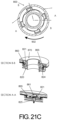
- FIG. 21 C a third step for connecting the first and second portions 820 and 870 of locking mechanism 800 is shown.
- FIG. 21 C shows the beginning of the twisting motion 902 a user must use on portion 870 , while keeping portion 820 from moving.
- the twisting motion 902 for turning portion 870 is a clockwise motion.
- each portion 861 of each protrusion 860 meets an inner surface of each ridge 821 .
- the flexible structure of protrusion 860 provides a biasing or clamping force when protrusions 860 come into contact with the inner surfaces of ridges 821 , so that the protrusions 860 pull the ridges 821 in a direction opposite of direction 901 as shown in FIG. 21 A .
- protrusions 860 come into contact with an angled surface of locking tab 825 , and force the locking tab downward in direction 901 , as the protrusion 860 passes over the angled surface.
- FIG. 21 D a fourth and final step for connecting the first and second portions 820 and 870 of locking mechanism 800 is shown.
- Rotation in clockwise direction 902 is completed when each protrusion 860 comes into contact with and is stopped by locking end portion 823 .
- Locking end portion 823 connects each ridge 821 to the rest of portion 820 as shown.
- Once protrusion 860 comes into contact with locking portion 823 it no longer has contact with the angled portion of locking tab 825 , and therefore no longer presses locking tab 825 downward.
- Locking tab 825 then returns to its initial resting position by moving back upwards in a direction opposite direction 901 , and comes into contact with the inner surface of ridge 821 .
- the protrusion 860 is then locked in place, preventing movement in a counter clock wise direction opposite that of direction 902 .
- a locking tab 825 is present at each location that a ridge 821 is present.
- only one locking tab 825 is present to lock only one protrusion 860 .
- the number of locking tabs 825 can vary as needed. In some embodiments, one, two, three, four or more locking tabs can be used in a locking mechanism 800 .
- a locking release mechanism (not shown) can be used by a user to release or lower the locking tab 825 to free each locked protrusion 860 , thereby allowing the locking mechanism 800 to be disconnected.
- a user can turn the portion 870 with enough force to overcome the biasing force of locking tab 825 , thereby forcing the locking tab down in a direction 901 , thereby releasing each locked protrusion 860 .
- Locking mechanism 800 can be used with non-circular waveguides such as square, triangular, oblong, elliptical, and other commonly used waveguide shapes.
Landscapes
- Waveguide Connection Structure (AREA)
Abstract
Description
Claims (16)
Priority Applications (1)
| Application Number | Priority Date | Filing Date | Title |
|---|---|---|---|
| US17/324,901 US11862833B2 (en) | 2021-05-19 | 2021-05-19 | Coupling assembly including a first waveguide with a first end and second waveguide with a second end, where a locking mechanism connects the first end to the second end |
Applications Claiming Priority (1)
| Application Number | Priority Date | Filing Date | Title |
|---|---|---|---|
| US17/324,901 US11862833B2 (en) | 2021-05-19 | 2021-05-19 | Coupling assembly including a first waveguide with a first end and second waveguide with a second end, where a locking mechanism connects the first end to the second end |
Publications (2)
| Publication Number | Publication Date |
|---|---|
| US20220376374A1 US20220376374A1 (en) | 2022-11-24 |
| US11862833B2 true US11862833B2 (en) | 2024-01-02 |
Family
ID=84102886
Family Applications (1)
| Application Number | Title | Priority Date | Filing Date |
|---|---|---|---|
| US17/324,901 Active 2041-06-06 US11862833B2 (en) | 2021-05-19 | 2021-05-19 | Coupling assembly including a first waveguide with a first end and second waveguide with a second end, where a locking mechanism connects the first end to the second end |
Country Status (1)
| Country | Link |
|---|---|
| US (1) | US11862833B2 (en) |
Citations (7)
| Publication number | Priority date | Publication date | Assignee | Title |
|---|---|---|---|---|
| US2774616A (en) * | 1953-05-07 | 1956-12-18 | Roy F Dodd | Quick release coupling having detachable screw thimble-gland |
| US2923994A (en) * | 1958-10-28 | 1960-02-09 | johnson | |
| US3039797A (en) * | 1959-01-26 | 1962-06-19 | Aircraft Armaments Inc | Quick disconnect waveguide coupling |
| US3817805A (en) * | 1971-11-26 | 1974-06-18 | L Surikov | Method of jointing pipes with internal heat-sensitive coating and joint based on said method |
| US4962991A (en) * | 1985-01-23 | 1990-10-16 | Raytheon Company | Quick-disconnect waveguide connector assembly |
| US6448875B1 (en) * | 2001-03-07 | 2002-09-10 | Matthew J. Sciarrino | Waveguide interconnection system |
| US20070252665A1 (en) * | 2006-05-01 | 2007-11-01 | Ems Technologies, Inc. | System for connecting waveguides |
-
2021
- 2021-05-19 US US17/324,901 patent/US11862833B2/en active Active
Patent Citations (7)
| Publication number | Priority date | Publication date | Assignee | Title |
|---|---|---|---|---|
| US2774616A (en) * | 1953-05-07 | 1956-12-18 | Roy F Dodd | Quick release coupling having detachable screw thimble-gland |
| US2923994A (en) * | 1958-10-28 | 1960-02-09 | johnson | |
| US3039797A (en) * | 1959-01-26 | 1962-06-19 | Aircraft Armaments Inc | Quick disconnect waveguide coupling |
| US3817805A (en) * | 1971-11-26 | 1974-06-18 | L Surikov | Method of jointing pipes with internal heat-sensitive coating and joint based on said method |
| US4962991A (en) * | 1985-01-23 | 1990-10-16 | Raytheon Company | Quick-disconnect waveguide connector assembly |
| US6448875B1 (en) * | 2001-03-07 | 2002-09-10 | Matthew J. Sciarrino | Waveguide interconnection system |
| US20070252665A1 (en) * | 2006-05-01 | 2007-11-01 | Ems Technologies, Inc. | System for connecting waveguides |
Also Published As
| Publication number | Publication date |
|---|---|
| US20220376374A1 (en) | 2022-11-24 |
Similar Documents
| Publication | Publication Date | Title |
|---|---|---|
| US11549533B2 (en) | Pin and grommet fastener accommodating two directional offset and related methods | |
| US20140152492A1 (en) | Portable satellite communication system | |
| US7094091B2 (en) | Swivel adapter | |
| US5714963A (en) | Antenna-to-radio quick-connect support device | |
| US9416913B2 (en) | Quick mount connector | |
| KR101586710B1 (en) | Fiber optic adapter with enhanced alignment | |
| CN105684238B (en) | For can blindmate cooperation electrical cable connector kickboard | |
| US7405708B2 (en) | Low profiled antenna | |
| US10638818B2 (en) | Slider with reboundable pull-tab | |
| US11862833B2 (en) | Coupling assembly including a first waveguide with a first end and second waveguide with a second end, where a locking mechanism connects the first end to the second end | |
| US10516198B2 (en) | Waveguide connector couplers and adapters | |
| US6404298B1 (en) | Rotatable waveguide twist | |
| CN105514557A (en) | Antenna waveguide quick connect coupler | |
| US8647148B2 (en) | High frequency interface and connecting device for connecting a high-frequency cable to the high frequency interface | |
| US11367941B2 (en) | Quick coupling assemblies | |
| US20110157821A1 (en) | Mounting apparatus for pci card | |
| US7053849B1 (en) | Switchable polarizer | |
| US4654613A (en) | Radar rotary joint | |
| TWM596507U (en) | Wireless access point device | |
| US11287857B2 (en) | Shell structure | |
| US6940472B2 (en) | Universal antenna adapter | |
| US4625188A (en) | Pivoting joint for ultra-high frequency waveguides | |
| US20100150647A1 (en) | Pipe fixture | |
| KR200452682Y1 (en) | Antenna support with bending structure | |
| US20240426332A1 (en) | Connector Component and Connector |
Legal Events
| Date | Code | Title | Description |
|---|---|---|---|
| FEPP | Fee payment procedure |
Free format text: ENTITY STATUS SET TO UNDISCOUNTED (ORIGINAL EVENT CODE: BIG.); ENTITY STATUS OF PATENT OWNER: SMALL ENTITY |
|
| AS | Assignment |
Owner name: NETQUI J.S.A., SLOVAKIA Free format text: ASSIGNMENT OF ASSIGNORS INTEREST;ASSIGNORS:MARCINCAK, MARTIN;SVIHURA, PETER;CAPEK, PAVOL;REEL/FRAME:056296/0939 Effective date: 20210517 |
|
| FEPP | Fee payment procedure |
Free format text: ENTITY STATUS SET TO SMALL (ORIGINAL EVENT CODE: SMAL); ENTITY STATUS OF PATENT OWNER: SMALL ENTITY |
|
| STPP | Information on status: patent application and granting procedure in general |
Free format text: NON FINAL ACTION MAILED |
|
| STPP | Information on status: patent application and granting procedure in general |
Free format text: FINAL REJECTION MAILED |
|
| STPP | Information on status: patent application and granting procedure in general |
Free format text: RESPONSE AFTER FINAL ACTION FORWARDED TO EXAMINER |
|
| STPP | Information on status: patent application and granting procedure in general |
Free format text: NOTICE OF ALLOWANCE MAILED -- APPLICATION RECEIVED IN OFFICE OF PUBLICATIONS |
|
| STPP | Information on status: patent application and granting procedure in general |
Free format text: PUBLICATIONS -- ISSUE FEE PAYMENT RECEIVED |
|
| STPP | Information on status: patent application and granting procedure in general |
Free format text: PUBLICATIONS -- ISSUE FEE PAYMENT VERIFIED |
|
| STCF | Information on status: patent grant |
Free format text: PATENTED CASE |