US11858733B2 - Waste disposal system having a manual actuator and a rotator - Google Patents
Waste disposal system having a manual actuator and a rotator Download PDFInfo
- Publication number
- US11858733B2 US11858733B2 US17/233,445 US202117233445A US11858733B2 US 11858733 B2 US11858733 B2 US 11858733B2 US 202117233445 A US202117233445 A US 202117233445A US 11858733 B2 US11858733 B2 US 11858733B2
- Authority
- US
- United States
- Prior art keywords
- waste
- rotator
- waste bag
- lid casing
- lid
- Prior art date
- Legal status (The legal status is an assumption and is not a legal conclusion. Google has not performed a legal analysis and makes no representation as to the accuracy of the status listed.)
- Active, expires
Links
- 239000002699 waste material Substances 0.000 title claims abstract description 185
- 238000004873 anchoring Methods 0.000 claims description 16
- 238000000034 method Methods 0.000 claims description 16
- 230000037452 priming Effects 0.000 claims description 8
- 230000001877 deodorizing effect Effects 0.000 claims description 2
- 239000000463 material Substances 0.000 claims description 2
- 238000007726 management method Methods 0.000 claims 1
- 239000010813 municipal solid waste Substances 0.000 abstract description 6
- 241000282326 Felis catus Species 0.000 description 9
- 239000004606 Fillers/Extenders Substances 0.000 description 9
- 230000007246 mechanism Effects 0.000 description 9
- 238000013461 design Methods 0.000 description 8
- 230000006835 compression Effects 0.000 description 7
- 238000007906 compression Methods 0.000 description 7
- 230000013011 mating Effects 0.000 description 6
- 230000002093 peripheral effect Effects 0.000 description 6
- 239000002184 metal Substances 0.000 description 3
- 238000012546 transfer Methods 0.000 description 3
- 230000008901 benefit Effects 0.000 description 2
- 238000012986 modification Methods 0.000 description 2
- 230000004048 modification Effects 0.000 description 2
- 238000007789 sealing Methods 0.000 description 2
- 239000002910 solid waste Substances 0.000 description 2
- 230000009471 action Effects 0.000 description 1
- 230000004075 alteration Effects 0.000 description 1
- 239000003610 charcoal Substances 0.000 description 1
- 238000010276 construction Methods 0.000 description 1
- 230000008878 coupling Effects 0.000 description 1
- 238000010168 coupling process Methods 0.000 description 1
- 238000005859 coupling reaction Methods 0.000 description 1
- 238000009434 installation Methods 0.000 description 1
- 238000004806 packaging method and process Methods 0.000 description 1
- 230000008569 process Effects 0.000 description 1
- 238000012545 processing Methods 0.000 description 1
- 238000006467 substitution reaction Methods 0.000 description 1
Images


Classifications
-
- B—PERFORMING OPERATIONS; TRANSPORTING
- B65—CONVEYING; PACKING; STORING; HANDLING THIN OR FILAMENTARY MATERIAL
- B65F—GATHERING OR REMOVAL OF DOMESTIC OR LIKE REFUSE
- B65F1/00—Refuse receptacles; Accessories therefor
- B65F1/04—Refuse receptacles; Accessories therefor with removable inserts
- B65F1/06—Refuse receptacles; Accessories therefor with removable inserts with flexible inserts, e.g. bags or sacks
-
- B—PERFORMING OPERATIONS; TRANSPORTING
- B65—CONVEYING; PACKING; STORING; HANDLING THIN OR FILAMENTARY MATERIAL
- B65F—GATHERING OR REMOVAL OF DOMESTIC OR LIKE REFUSE
- B65F1/00—Refuse receptacles; Accessories therefor
- B65F1/14—Other constructional features; Accessories
- B65F1/16—Lids or covers
- B65F1/1615—Lids or covers with means for locking, fastening or permanently closing thereof
-
- B—PERFORMING OPERATIONS; TRANSPORTING
- B65—CONVEYING; PACKING; STORING; HANDLING THIN OR FILAMENTARY MATERIAL
- B65F—GATHERING OR REMOVAL OF DOMESTIC OR LIKE REFUSE
- B65F1/00—Refuse receptacles; Accessories therefor
- B65F1/04—Refuse receptacles; Accessories therefor with removable inserts
- B65F1/06—Refuse receptacles; Accessories therefor with removable inserts with flexible inserts, e.g. bags or sacks
- B65F1/068—Refuse receptacles; Accessories therefor with removable inserts with flexible inserts, e.g. bags or sacks with means aiding the removal of the flexible insert
-
- B—PERFORMING OPERATIONS; TRANSPORTING
- B65—CONVEYING; PACKING; STORING; HANDLING THIN OR FILAMENTARY MATERIAL
- B65F—GATHERING OR REMOVAL OF DOMESTIC OR LIKE REFUSE
- B65F1/00—Refuse receptacles; Accessories therefor
- B65F1/14—Other constructional features; Accessories
- B65F1/16—Lids or covers
- B65F1/1607—Lids or covers with filling openings
-
- B—PERFORMING OPERATIONS; TRANSPORTING
- B65—CONVEYING; PACKING; STORING; HANDLING THIN OR FILAMENTARY MATERIAL
- B65F—GATHERING OR REMOVAL OF DOMESTIC OR LIKE REFUSE
- B65F1/00—Refuse receptacles; Accessories therefor
- B65F1/14—Other constructional features; Accessories
- B65F2001/1653—Constructional features of lids or covers
- B65F2001/1676—Constructional features of lids or covers relating to means for sealing the lid or cover, e.g. against escaping odors
-
- B—PERFORMING OPERATIONS; TRANSPORTING
- B65—CONVEYING; PACKING; STORING; HANDLING THIN OR FILAMENTARY MATERIAL
- B65F—GATHERING OR REMOVAL OF DOMESTIC OR LIKE REFUSE
- B65F2210/00—Equipment of refuse receptacles
- B65F2210/129—Deodorizing means
-
- B—PERFORMING OPERATIONS; TRANSPORTING
- B65—CONVEYING; PACKING; STORING; HANDLING THIN OR FILAMENTARY MATERIAL
- B65F—GATHERING OR REMOVAL OF DOMESTIC OR LIKE REFUSE
- B65F2210/00—Equipment of refuse receptacles
- B65F2210/167—Sealing means
-
- B—PERFORMING OPERATIONS; TRANSPORTING
- B65—CONVEYING; PACKING; STORING; HANDLING THIN OR FILAMENTARY MATERIAL
- B65F—GATHERING OR REMOVAL OF DOMESTIC OR LIKE REFUSE
- B65F2220/00—Properties of refuse receptacles
- B65F2220/128—Properties of refuse receptacles transparent
-
- B—PERFORMING OPERATIONS; TRANSPORTING
- B65—CONVEYING; PACKING; STORING; HANDLING THIN OR FILAMENTARY MATERIAL
- B65F—GATHERING OR REMOVAL OF DOMESTIC OR LIKE REFUSE
- B65F2240/00—Types of refuse collected
- B65F2240/132—Diapers
Definitions
- the present disclosure relates to a waste disposal system, more particularly, a waste pail with a replaceable waste bag suitable for various types of solid waste, including cat litter and soiled diapers.
- a waste pail is a garbage can for receiving and holding waste articles.
- many waste pails have a pivoting top lid so that odor is kept within the waste pail.
- waste pails use a foot pedal mechanism to open the lid.
- a waste pail having a foot pedal requires that it be placed at a location with sufficient clearance around the foot pedal so a user may access the foot pedal.
- foot pedals are not user-friendly for younger children and foot pedals can be aesthetically unpleasing.
- the contemplated waste disposal pail can have a bottom drum and a top drum.
- the bottom drum holds a waste bag/liner while the top drum contains necessary mechanism to control a rotational movement of a collar which is placed over the top opening of the bottom drum.
- the top drum can include a lid casing and a manual actuator.
- the manual actuator can be located on the top side of the lid casing to indirectly control the rotational movement of the collar.
- the manual actuator can have a vertical movement (e.g., push button) or a rotational movement (e.g., a turn knob or turn dial).
- the manual actuator can either directly or indirectly cause a rotator to rotate.
- the rotator can also be disposed within the lid casing or under the lid casing to make direct or indirect engagement with the collar.
- the optional gears can also be of different sizes to provide a mechanical advantage which allows for an improved speed and/or torque of the rotator.
- the lid casing of the top drum can be transparent or semi-transparent to show movement of any internal components such as gears.
- the rotator underneath the lid casing either directly or indirectly (e.g., via a lid insert) engages with the rotatable collar such that when the rotator rotates, the collar also rotates.
- the top lid can be pivotably coupled to the bottom drum via a hinge, but this disclosure is not limited thereto.
- an optional lid insert can be provided between the rotator and the collar.
- the lid insert can have a funnel shape to contain the waste article before the waste article can drop into the inside of the waste bag.
- the manual actuator can control the rotational movement of the collar only when the lid casing is closed onto the bottom drum. Therefore, a user may not be able to use the manual actuator to untwist the neck of the waste bag until the lid casing is closed. In this way, nuisance garbage odor from inside the waste bag is prevented from wafting towards the user.
- the lid insert can be pivotably coupled to the collar via a hinge.
- the top rim of the waste bag can be anchored to the rotatable collar which fits over the bottom drum.
- a part of the waste bag can be anchored to the bottom drum such that when the collar rotates relative to the bottom drum, waste bag is caused to twist at its neck region, effectively sealing off the odor-causing articles within the waste bag.
- the bag frame of the waste bag can be foldable and can have several tabs.
- Each of the tabs can have an aperture for fitting over the engagers of the inner drum.
- the tab can also have a notch to keep a twisted neck of the waste bag closed when carrying out the waste bag.
- the waste bag can have at least one tether or strap to fasten to the inner wall of the bottom drum. In this way, when the top rim of the waste bag rotates with the collar, the tether or the strap twists around a neck of the waste bag. In another embodiment, the tether or the strap causes a neck of the waste bag to twist into a twisted configuration.
- the tether of the waste bag can be attached to a mid-portion of the waste bag such that when the neck of the waste bag is twisted, a funnel shape can be formed above the twisted neck of the waste bag.
- the tether of the waste bag can be attached near the top rim of the waste bag.
- the bottom drum can be easily disassembled. For example, to remove a heavy bag of cat litter from the bottom drum, a user may first twist off a top half portion of the bottom drum thereby making it easier to pull the bag of cat litter out of the bottom drum.
- the various part of the waste pail can be easily assembled by an end consumer, thereby allowing the waste pail to be shipped in disassembled parts nestled into a much smaller dimension.
- the bottom container can have two sections physically separable from each other.
- One of the sections can be replaced with a shorter section to create a smaller waste pail for certain special uses such as disposal of cat litter.
- the current disclosure provides a novel method of operating a waste management.
- the novel method includes keeping a portion of the waste bag tethered to an interior wall of the bottom drum while anchoring the top rim of the waste bag to a rotatable collar.
- the neck portion of the waste bag can be twisted/untwisted by rotating the collar.
- the novel method includes priming the waste bag by manually rotating the collar first to effectively twist a neck of the waste bag prior to use.
- FIG. 1 is a perspective view of an embodiment of a contemplated waste pail according to an aspect of the embodiment.
- FIG. 2 is a perspective view of the contemplated waste pail of FIG. 1 having disassembled parts nestled together into a smaller profile for shipping, according to an aspect of the embodiment.
- FIG. 3 is a perspective view of another embodiment of a contemplated waste pail having a lid insert, according to an aspect of the embodiment.
- FIG. 4 is a perspective view of the contemplated waste pail of FIG. 3 with the lid insert halfway pivoted open, according to an aspect of the embodiment.
- FIG. 5 is a cross-sectional view of the contemplated waste pail of FIG. 3 , according to an aspect of the embodiment.
- FIG. 6 is a close-up view of the lid insert shown in FIG. 3 , according to an aspect of the embodiment.
- FIG. 7 is a perspective view of the contemplated waste pail of FIG. 4 with the lid insert fully pivoted open and a waste bag being placed into the bottom drum, according to an aspect of the embodiment.
- FIG. 8 is a close-up view of the bag frame of the waste bag as shown in FIG. 7 , according to an aspect of the embodiment.
- FIG. 9 is a perspective view of the contemplated waste pail of FIG. 7 with the lid insert fully pivoted open and a waste bag fully attached to the collar, according to an aspect of the embodiment.
- FIG. 10 is a close-up view of the bag frame of the waste bag as shown in FIG. 9 , according to an aspect of the embodiment.
- FIG. 11 is a cross-sectional view of the contemplated waste pail of FIG. 9 , showing two tethers wrapped around the neck of the waste bag, according to an aspect of the embodiment.
- FIG. 12 is a cross-sectional view of the contemplated waste pail of FIG. 9 with the lid insert enclosing over the collar, according to an aspect of the embodiment.
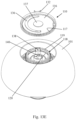
- FIG. 13 A is an exploded view of the contemplated components inside of a lid casing having a turn dial/turn knob as the manual actuator, according to an aspect of the embodiment.
- FIG. 13 B is close-up view of FIG. 13 A showing the bottom plate of the turn knob, an intermediate gear, and a secondary gear, according to an aspect of the embodiment.
- FIG. 13 C is a perspective view of the lid casing of FIG. 13 A with the turn knob removed, according to an aspect of the embodiment.
- FIG. 13 D is a perspective view of the lid casing of FIG. 13 A with the turn knob and the flat spiral spring removed, according to an aspect of the embodiment.
- FIG. 13 E is a perspective view of the lid casing of FIG. 13 A with the turn knob, the flat spiral spring, and the bottom plate of the turn knob removed, according to an aspect of the embodiment.
- FIG. 13 F is a top view of the lid casing of FIG. 13 E with the turn knob, the flat spiral spring, the bottom plate of the turn knob removed, showing the intermediate gear and the secondary gear matingly engaged together in a non-coaxial placement, according to an aspect of the embodiment.
- FIG. 13 G is a perspective view of the lid casing of FIG. 13 A with the turn knob, the flat spiral spring, the bottom plate of the turn knob, and the intermediate gear removed, according to an aspect of the embodiment.
- FIG. 14 A is a perspective view of another contemplated lid casing having a turn knob shown here with the turn knob removed, according to an aspect of the embodiment.
- FIG. 14 B is another view of the lid casing of FIG. 14 A now showing the entirety of the driving gear in mating engagement with a secondary gear; the driving gear being biased by a spring, according to an aspect of the embodiment.
- FIG. 14 C is a perspective view of the lid casing of FIG. 14 B with the spring removed, according to an aspect of the embodiment.
- FIG. 14 D is a perspective view of the lid casing of FIG. 14 C with the driving gear removed, exposing the secondary gear and a circular wall, according to an aspect of the embodiment.
- FIG. 15 A is a perspective view of yet another contemplated lid casing having a turn knob shown with the turn knob removed, exposing a spring-biased driving gear in mating engagement with a secondary gear, according to an aspect of the embodiment.
- FIG. 15 B is a perspective view of the contemplated lid casing of FIG. 15 A from a different angle to show the driving gear in its entirety, according to an aspect of the embodiment.
- FIG. 15 C is a perspective view of the contemplated lid casing of FIG. 15 B with the spring removed, according to an aspect of the embodiment.
- FIG. 15 D is a perspective view of the contemplated lid casing of FIG. 15 C with the driving gear removed, leaving behind a circular wall, according to an aspect of the embodiment.
- FIG. 16 is a perspective view of yet another contemplated lid casing having a button as the manual actuator, according to an aspect of the embodiment.
- FIG. 17 A is perspective view of still another contemplated lid casing where the button is removed, exposing the inner components within, according to an aspect of the embodiment.
- FIG. 17 B is a perspective view of the contemplated lid casing of FIG. 17 A with the compression springs and torsion spring removed, leaving behind a driving gear, two intermediate gears, a secondary gear, according to an aspect of the embodiment.
- FIG. 17 C is a perspective view of the contemplated lid casing of FIG. 17 B with one of the two intermediate gears removed, according to an aspect of the embodiment.
- FIG. 17 D is a perspective view of the contemplated lid casing of FIG. 17 B with both intermediate gears removed, according to an aspect of the embodiment.
- FIG. 17 E is a perspective view of the contemplated lid casing of FIG. 17 D with the driving gear removed, according to an aspect of the embodiment.
- FIG. 18 A is perspective view views of yet another contemplated lid casing along with two close-up views of the associated inner components.
- the button is removed, exposing the inner components within, according to an aspect of the embodiment.
- FIG. 18 B is a perspective view of the contemplated lid casing of FIG. 18 C with the driving gear, compression spring, and torsion spring removed, according to an aspect of the embodiment.
- FIG. 19 illustrates another embodiment of the waste pail where the rotator directly connects to the inner collar without a lid insert, according to an aspect of the embodiment.
- FIG. 20 is an exploded view of yet another embodiment of a top drum where no gears are used, according to an aspect of the embodiment.
- FIG. 21 is an enlarged view of a portion of FIG. 20 , according to an aspect of the embodiment.
- FIG. 22 is an enlarged view of a portion of FIG. 20 , according to an aspect of the embodiment.
- FIG. 23 is an enlarged view of a portion of FIG. 20 , according to an aspect of the embodiment.
- FIG. 24 is a perspective view of another embodiment of the top drum, according to an aspect of the embodiments.
- FIG. 25 is a perspective view of the top drum of FIG. 24 with the module removed, according to an aspect of the embodiments.
- FIG. 26 is a perspective view of the top drum of FIG. 24 with the module and rotator removed, according to an aspect of the embodiments.
- FIG. 27 is a perspective view of the module of FIG. 25 , according to an aspect of the embodiments.
- FIG. 28 is an exploded view of the module of FIG. 26 , according to an aspect of the embodiments.
- FIG. 29 is an exploded view of the module of FIG. 26 , according to an aspect of the embodiments.
- FIG. 30 illustrates a pully bar within the module housing, according to an aspect of the embodiments.
- FIG. 31 illustrates the pulley bar of FIG. 30 being disassembled, according to an aspect of the embodiments.
- FIG. 32 illustrates how the pull-string is wound around the circular track, according to an aspect of the embodiments.
- FIG. 33 is a perspective view of the module housing, according to an aspect of the embodiments.
- FIG. 34 is an exploded view of the module housing with a torsion spring, according to an aspect of the embodiments.
- FIG. 35 is a perspective view of the module housing with the torsion spring in place, according to an aspect of the embodiments.
- FIG. 36 is an exploded view of the top drum of FIG. 24 , according to an aspect of the embodiments.
- co-axial in conjunction with inner components within the lid casing refers to a relative position of component and does not infer whether or not the two components are physically connected by the same axle/shaft.
- first gear and a second gear when a first gear and a second gear are described as being co-axial, it means both of these two gears rotate on the same rotational axis, but not necessarily physically connected to the same axle/shaft. In other words, their rotational axes align.
- a first gear and a second gear are described as being not co-axial, that means their rotational axes do not align.
- this disclosure is related to an apparatus for a novel method of managing waste.
- the apparatus is contemplated to be a waste pail that can receive and store various types of waste articles.
- this can be a waste pail specific for soiled diapers or cat litter.
- Other types of waste articles are also specifically contemplated, especially odorous waste articles.
- the basic structure of the contemplated waste pail 1 can include a top drum 2 to fit over a bottom drum 3 .
- the top drum 2 can have a lid casing 101 that encloses various components all of which will be described in more detail below.
- the bottom drum 3 can be a barrel shaped container with an empty enclosure within which a waste bag/liner can be enclosed.
- the waste bag/liner will be described in more detail below.
- the scoop 8 can be particularly useful if the waste pail is being used to hold cat litter.
- the bottom drum 3 can be of a single-piece construction in one embodiment. In another embodiment, such as the one shown in FIG. 1 , the bottom drum 3 can come in two separable pieces.
- bottom drum 3 has an upper portion 4 detachably attached to a lower portion 5 .
- Upper portion 4 may connect to the lower portion 5 using any known mechanical means.
- the upper portion 4 may clip onto the lower portion 5 , or they may twist/screw onto each other. There can also be fasteners to detachably attached the two pieces together.
- One embodiment provides a lower portion 5 having a slightly tapered bottom end such that its bottom end has a smaller dimension such that it is small enough to fit partially or fully within the upper portion 4 during storage and shipping.
- FIG. 2 shows the waste pail 1 with a smaller profile made possible by turning the lower portion 5 upside down and then fit the upper portion 4 over it.
- the lower portion 5 is nestled partially within the upper portion 4 .
- the two-piece configuration can also be helpful especially when taking a bag of cat litter out of the bottom drum 3 .
- a user may twist to easily unlock and remove the upper portion 4 from the lower portion 5 . In this way, the bag of cat litter can be pulled out without accidentally tearing the bag.
- the lid casing 101 can be pivotably attached to the bottom drum 2 via an outer hinge 109 .
- a user can manually lift the lid casing 101 , revealing what is underneath the lid casing 101 thereby showing what is on top of the bottom drum 2 .
- a rotator 102 Under the lid casing 101 there can be a rotator 102 which has apertures that function as catchers 103 .
- the deodorizer 108 can have a perforated door that can open to reveal a compartment to hold charcoal packets, other odor absorbing sachet, deodorizing pouches, or scented packets.
- the perforated door can be hinged to the rotator 102 ; the perforated door can clip and lock into position. The function and mechanical detail of the rotator 102 will be described in more detail later.
- the lid insert 19 can have a generally funnel-shape; the lid insert 19 can guide the entry of waste articles down into the waste bag.
- the lid insert 19 can be particularly helpful to keep the waste article, e.g., cat litter, from spilling over.
- the lid insert 19 can be easily moved out of the way when installing a waste bag into the bottom drum 3 .
- lid insert 19 is shown to be pivotably attached to the inner collar 121 via the inner hinge 125 .
- the lid insert 19 can be attached to the waste pail 1 in other ways. For example, it can matingly fit over the inner collar 121 without the inner hinge 125 . In this way, a user can completely remove the lid insert 19 away from the inner collar 121 .
- FIGS. 5 and 6 illustrate the working relationship of lid insert 19 , inner collar 121 , and outer collar 122 .
- the lid insert 19 can be a hollow structure having protuberances 151 disposed along its top ridge. These protuberances 151 can couple to the corresponding catchers 103 of the rotator 102 .
- the lid insert 19 cannot rotate independently of the inner collar 121 . In other words, when the lid insert 19 rotates, the inner collar 121 also rotates.
- protuberances 151 are each shown as a stubby protrusion, there can be other types of structure in other shapes and sizes to achieve the same function.
- Inner collar 121 fits over the outer collar 122 in a track and groove mechanism such that the inner collar 121 can freely rotate relative to a stationary outer collar 122 .
- the outer collar 122 is fastened (e.g., by friction, screw blade, clip, etc.) to the top rim 6 of the upper portion 4 of the bottom drum.
- the outer collar 122 can be pivotably coupled to the top rim 6 of the upper portion 4 of the bottom drum via the outer hinge 109 . In this way, a user may pivot open (i.e., tilt back) the inner collar 121 and outer collar 122 together, thereby providing easier access to the interior of the bottom drum 3 .
- a user may pivot open the lid casing 101 , inner collar 121 and outer collar 122 together at once, because these three parts can all be pivoted on the outer hinge 109 .
- a user may first pivot open the inner collar 121 and outer collar 122 .
- the entire waste bag 10 can then be dropped into the interior of the bottom drum 3 .
- the user can then close down the inner collar 121 and outer collar 122 while manually taking the bag frame 12 of the waste bag 10 and pass it through the circular opening of the inner collar 121 and outer collar 122 .
- the outer collar 122 remains stationary while the inner collar 121 can rotate along with the lid insert 19 .
- the waste pail 1 without the optional lid insert 19 .
- a waste bag 10 can be provided in the bottom drum 3 .
- the waste bag 10 is shown partially inserted into the bottom drum 3 with its bag frame 12 yet to be secured to the inner collar 121 .
- the bag frame 12 lines the opening of the waste bag 10 .
- the top rim of the waste bag 10 can have a retaining feature so that the top rim of the waste bag 10 can be secured to the inner collar 121 .
- the bag frame 12 can be made of various types of material such as plastic, rubber, and paper.
- the bag frame 12 can be flexible or foldable so that if needed, it can be entirely inserted through the inner collar 121 .
- Bag frame 12 can have tabs 15 each of which with an aperture 16 .
- the inner collar 121 can have protuberances 151 to insert through the corresponding apertures 16 of the bag frame 12 .
- protuberances 151 can couple with their corresponding apertures 16 of corresponding sizes and shapes.
- the tab 15 of the bag frame 12 can have a notch 17 .
- the user can wrap the tether/strap 18 around the neck of the waste bag 10 (whether the neck is twisted) and then loop the tether/strap 18 over some part (e.g., the middle part) of the folded bag frame 12 and secure the tether/strap 18 in the notch 17 before carrying the waste bag 10 to the dumpster. This can minimize the escape of odor from the waste bag 10 during transport.
- this notch 17 can also function as a tie strap.
- the user can manually twist the neck of the waste bag and then fit the twisted neck into the notch 17 thereby keeping it twisted shut. The user may next carry the waste bag away without having to tie a knot.
- the inner collar 121 can use a set of protuberances 151 of different diameters, which are illustrated in FIG. 8 .
- the tabs 15 of the waste bag 10 also have corresponding different diameters of apertures 16 .
- FIG. 10 illustrates the embodiment where the lid insert 19 is pivotably coupled to the inner collar 121 via inner hinge 125 .
- the waste bag 10 should be “primed” by manually rotating the entire lid insert 19 and inner collar 121 combination in a preset direction and degree of angle. For example, a user can be asked to prime the waste bag clockwise 360 degrees.
- the direction of priming should be opposite to the driving direction of rotator 102 so that priming keeps the waste bag 10 twisted, while driving of the rotator untwists the waste bag 10 .
- the relationship between the rotator 102 and the waste bag 10 will be further explained in association with FIGS. 13 A through 19 .
- Priming can be performed while the lid insert 19 is either in an up or down position. Preferably, it would be easier to rotate the inner collar 121 while the lid insert 19 is down and in a position directly over the inner collar 121 .
- FIGS. 11 and 12 illustrate the twisted waste bag 10 after the waste bag 10 has been primed by the aforementioned method. Here, the priming direction is counter-clock wise from a top view of the waste pail 1 .
- the waste bag 10 In operation, the waste bag 10 would remain twisted at rest, until a user is ready to drop a waste article into the waste bag 10 .
- the waste bag 10 can have tethers 18 already attached to a region near the neck, above the neck, or below the neck of the waste bag 10 . In other words, these are specialty waste bags 10 made at the manufacturer with tethers 18 attached.
- a user can attach the free end of each tether 18 to its corresponding attachment point 20 to ensure proper closure by twisting of the tethers 18 .
- These attachment points 20 can be located on the inside wall of the bottom drum 3 .
- the attachment points 20 can be of different mechanical structures. For example, it can be a clip, a notch, a hook, etc.
- the user may simply reach through the circular opening of the inner collar 121 .
- the user may pivot open the lid insert 19 /inner collar 121 /outer collar 122 assembly from the top rim 6 of the bottom drum 3 for better access.
- each tether 18 remains secured to the attachment points 20 while the opposite ends of the tether 18 moves in a circular fashion along with the bag frame 12 . This motion can cause the two tethers 18 to crisscross each other thereby sealing off the waste bag 10 by wrapping around the neck of it. In one embodiment, the neck region is also twisted shut, or partially twisted.
- FIG. 12 illustrates a primed waste bag 10 where the lid insert 19 is in a down position over the inner collar 121 .
- the neck of the waste bag 10 is closed off or sealed off. In one embodiment, this provides a complete closure of the waste bag 10 . In another embodiment, this provides a near-complete closure of the waste bag 10 .
- the body portion or the bottom portion of the waste bag 10 may or may not have any secure attachment to the bottom drum 3 . In other words, the body, or the bottom portion of the waste bag 10 may simply remain in place without being secured to the bottom drum in any other way. This is notable because in some embodiments, the body of the bag does not need to be secured in place to twist the neck of the waste bag 10 . In the embodiment shown, the neck or the body portion of the waste bag 10 itself is not heavily twisted. The tethers 18 are twisted to create a crisscrossing closure even when the waste bag 10 itself remain untwisted or only partially twisted.
- a primed waste bag 10 remains closed until a user is ready to drop a waste article down into it. This can be accomplished by using certain mechanisms within the lid casing 101 as will be described below in association with FIGS. 13 A through 19 .
- the lid casing 101 When the lid casing 101 is closed, the user may manually operate an actuator such as a turn knob 105 ( FIGS. 1 , 2 , 13 A, 13 C ) or a push button 4105 ( FIGS. 16 , 17 A, 18 A ) to cause the rotator 102 to rotate in a driving direction opposite to the priming direction.
- an actuator such as a turn knob 105 ( FIGS. 1 , 2 , 13 A, 13 C ) or a push button 4105 ( FIGS. 16 , 17 A, 18 A ) to cause the rotator 102 to rotate in a driving direction opposite to the priming direction.
- the lid insert 19 , the inner collar 121 , and the bag frame 12 all move in the same driving direction, thereby causing the tethers 18 to untwist.
- the waste bag 10 opens which allows the waste article to drop into the waste bag, while the lid casing 101 remains closed. This can be important because in a typical trash can, the odor from within the waste bag would undesirably waft towards the user when the user disposes of a waste article into the waste bag.
- the waste bag 10 remains closed when a user disposes of a waste article. This would keep odor sealed in during the disposal process.
- FIGS. 13 A- 13 G There can be various types of mechanism to operate the rotator 102 .
- a turn knob 105 disposed on top of the lid casing 101 .
- the turn knob 105 can rotate relative to the lid casing 101 .
- Turn knob 105 is coupled to a bottom plate 116 to form an enclosure within which a flat torsion spring 115 can be housed.
- the flat torsion spring 115 has a spiral configuration. Its peripheral free end can be attached to a stationary side post 138 (see FIG. 13 D ) which extends through the arcuate opening 136 of the bottom plate 116 .
- the center free end of the flat torsion spring 115 can be exposed through a center opening 137 (see FIG. 13 B ) of the bottom plate 116 so that the center free end of the flat torsion spring 115 can be securely attached to a slit on a center post 140 .
- the center post 140 is an integral part of secondary gear 111 so it can rotate along with the secondary gear 111 . Note that the center post 140 does not necessarily have to be in absolute rotational center of the turn knob 105 or secondary gear 111 .
- the rotational axis 152 of the secondary gear 111 is shown in FIG. 13 F . Being secured to the rotatable center post 140 at one end and secured to the stationary side post 138 at the other end, the flat torsion spring 115 biases the secondary gear in a particular direction.
- the bottom plate 116 of the turn knob 105 can have four raised columns 132 to be received into four corresponding receiving slots 130 (see FIG. 13 C ) on the underside of the turn knob 105 .
- the arcuate opening 136 can provide a passage for the stationary side post 138 (see FIG. 13 D ) when the bottom plate 116 rotates relative to the stationary side post 138 .
- a retaining wall 134 can be provided on the surface of the bottom plate 116 to guide the flat torsion spring 115 .
- the intermediate gear 118 can have a ring shape which can have a diameter large enough to fit the secondary gear 111 .
- the intermediate gear 118 can have a diameter smaller than the driving gear 110 (see FIG. 13 E ).
- the driving gear 110 is part of the bottom plate 116 of the turn knob 105 .
- the underside of the bottom plate has inward-facing teeth 117 to matingly engage with the outward-facing teeth 119 of the intermediate gear 118 .
- the intermediate gear 118 and the driving gear 110 are not co-axial.
- FIG. 13 F A top view shown in FIG. 13 F can better illustrate the spatial relationship between the gears.
- the large top circular opening of the lid casing 101 can represent the approximate location and diameter of the driving gear 110 .
- the driving gear 110 is co-axial with the secondary gear 111 .
- the rotational axis 156 of the driving gear 110 is the same as the rotational axis 152 of the secondary gear 111 .
- the inward-facing teeth of the driving gear 110 and the entire driving gear 110 is kept in a centering position by the retaining wall 144 .
- the retaining wall 144 is a structure similar to the retaining wall 134 of FIG. 13 B .
- the retaining wall can be an integral part of the floor 175 which remains stationary.
- the inward-facing teeth of the driving gear 110 make mating engagement with the outward-facing teeth of the intermediate gear 118 .
- the intermediate gear 118 is offset from the driving gear 110 , which is not co-axial with the intermediate gear 118 .
- the intermediate gear 118 is held in position by a retaining wall 145 which is shown in FIG. 13 G .
- the intermediate gear 118 has been removed to reveal the secondary gear 111 and the retaining wall 145 .
- the retaining wall 145 can be an integral part of the floor 175 .
- the floor 175 remains stationary along with the retaining wall 145 and the side post 138 .
- the intermediate gear 118 of FIG. 13 E can have inward-facing teeth 120 to make mating engagement with the outward-facing teeth of the secondary gear 111 .
- the secondary gear 111 is not an integral part of the floor 175 , therefore, it can rotate relative to the floor 175 .
- the spring-biased secondary gear 111 when driven to rotate, it co-axially rotates the rotator 102 (see FIGS. 3 - 7 ) which is disposed under the floor 175 and separably movable relative to the floor 175 .
- the secondary gear 111 is coupled to the rotator 102 via an axle (not shown).
- the spring-biased secondary gear 111 transfers the biasing force to the turn knob 105 such that at rest, the turn knob 105 is at a position to keep the waste bag 10 in a primed position.
- the rotator 102 turns in a direction to untwist the waste bag 10 .
- the biasing force can return the waste bag 10 into a twisted configuration.
- FIGS. 14 A- 14 D illustrate yet another contemplated mechanism with the lid casing 2101 , which can be pivotably coupled to the upper portion 4 of bottom drum 3 via an outer hinge 2109 .
- the turn knob 2105 has a vertical rod 2188 disposed on its underside.
- the underside of the turn knob 2105 also has a center post with a rotational axis 2158 that is co-axial with the rotational axis of the secondary gear 2111 .
- the secondary gear 2111 can have a hollow center within which the center post of the turn knob 2105 can fit.
- the vertical rod 2188 fits within a linear slot 2181 of a distal guide 2180 .
- the distal guide 2180 is an integral part of the driving gear 2110 .
- the driving gear 2111 in this embodiment is fan-shaped with an arcuate opening 2161 which has inward-facing teeth.
- the driving gear 2111 rotates about its rotational axis 2156 and is biased by a torsion spring 2115 .
- FIG. 14 B shows the torsion spring 2115 anchored into the floor 2175 .
- the floor 2175 is stationary and does not rotate.
- the vertical rod 2188 moves the distal guide 2180 thereby swings the fan-shaped driving gear 2110 in one direction.
- the driving gear 2110 swings in one direction relative to the stationary floor 2175 , it causes the secondary gear 2111 to rotate relative to the stationary floor 2175 .
- the secondary gear 2111 is co-axial with and coupled to the rotator 102 ( FIGS. 1 - 6 ) such that when the secondary gear 2111 rotates, the rotator 102 also rotates.
- FIG. 14 C illustrates the fan-shaped driving gear 2110 with the torsion spring 2115 removed.
- the driving gear 2110 is removed to reveal a circular wall 2183 .
- the circular wall 2183 is an integral part of the floor 2175 which remains stationary.
- the circular wall 2183 functions to keep the fan-shaped driving gear 2110 in a rotational position to rotate along an axis that is co-axial with the circular wall 2183 .
- FIGS. 15 A- 15 D illustrate a design similar the design in FIGS. 14 A- 14 D .
- the major difference between the two designs is the location of the distal guide 2180 .
- the distal guide 3180 is located on the opposite end of the fan-shaped driving gear 3110 .
- disposed on the lid casing 3101 is a turn knob 3105 with a vertical rod 3188 disposed on its underside.
- the underside of the turn knob 3105 also has a center post having a rotational axis 3158 that is co-axial with the rotational axis of the secondary gear 3111 .
- the secondary gear 3111 can have a hollow center within which the center post of the turn knob 3105 can fit.
- the vertical rod 3188 fits within a short linear slot 3181 of the distal guide 3180 .
- the distal guide 3180 can be an integral part of the driving gear 3110 .
- the driving gear 3111 in this embodiment is fan-shaped with an arcuate opening 3161 having inward-facing teeth. Being biased by a torsion spring 3115 , the driving gear 3111 can rotate about its rotational axis 3156 .
- FIG. 15 B shows the torsion spring 3115 anchored into the floor 3175 . The floor 3175 is stationary and does not rotate. When a user turns the turn knob 3105 , the vertical rod 3188 moves the distal guide 3180 thereby swings the fan-shaped driving gear 3110 in one direction.
- the driving gear 3110 swings in one direction relative to the stationary floor 3175 , it causes the secondary gear 3111 to rotate relative to the stationary floor 3175 .
- the secondary gear 3111 is co-axial with and coupled to the rotator 102 ( FIGS. 1 - 6 ) such that when the secondary gear 3111 rotates, the rotator 102 also rotates.
- FIG. 16 illustrates an embodiment where the manual actuator is a push button 4105 disposed on top of the lid casing 4101 .
- FIG. 16 is in simplified view where the bottom drum 3 is not shown.
- this embodiment of manual actuator can have the same bottom drum 3 , inner collar 121 , outer collar 122 , and waste bag 10 .
- FIGS. 17 A- 17 E regarding yet another embodiment of the push button mechanism enclosed within the lid casing 4101 .
- the manual actuator is a push button 4105 with its underside shown. The top side of this push button 4105 is shown in FIG. 16 .
- the underside of the push button 4105 can have a center rod 4196 disposed at the center.
- the center rod 4196 can be co-axial with the secondary gear 4111 .
- the secondary gears 4111 can remain within the lid casing 4101 such that when the push button 4105 is installed onto the lid casing 4101 , the center rod 4196 would be directly above the secondary gear 4111 .
- this center rod 4196 is not necessarily present.
- the center rod 4196 is non-movable relative to the push button 4105 .
- the center rod 4196 can be an integral part of the push button 4105 .
- FIG. 17 A There can be three anchoring posts 4192 vertically extending from the bottom of the push button 4105 . Each of the three anchoring posts 4192 is non-movable relative to the push button 4105 . When the push button 4105 is installed onto the lid casing 4101 , these three anchoring posts 4192 are received within three corresponding anchoring sleeves 4191 . These anchoring sleeve 4191 are shown in FIG. 17 A with a compression spring 4190 fitted over each. FIGS. 17 B- 17 E provide a better view of the anchoring sleeve 4191 where the compression springs 4190 have been removed. These three compression springs 4190 can provide a biasing force against a downward movement of the push button 4105 .
- FIG. 17 A the stationary floor 4175 is partially shown through the three arcuate openings 4161 of the driving gear 4110 .
- FIG. 17 E shows the stationary floor 4175 with the driving gear 4110 removed.
- the three anchoring posts 4192 can be received within the three corresponding anchoring sleeves 4191 all of which do not rotate.
- the push button 4105 also do not rotate during any steps of operating the push button 4105 . Instead, the downward action of the push button 4105 causes the driving gear 4110 to rotate relative to the floor 4175 and the three anchoring sleeves 4191 .
- FIG. 17 E A better view of the driving gear 4110 is shown in FIG. 17 E with the driving gear 4110 removed from the lid casing 4101 .
- the driving gear 4110 has a disc structure with three arcuate openings 4161 . In between the arcuate openings 4161 there can be three curved receiving surfaces 4198 .
- the secondary gear 4111 which can be coupled to the rotator 102 (see FIGS. 1 - 4 ).
- the secondary gear can rotate together with the rotator 102 relative to the floor 4175 which remains stationary during the operation of the waste pail 1 .
- FIG. 17 B illustrates the driving gear 4110 with the torsion spring 4115 and compression springs 4190 removed.
- the inward-facing teeth 4117 of the driving gear 4110 is in mating engagement with an intermediate gear 4118 .
- This intermediate gear 4118 is rotatably fixed in place by one of the three anchoring sleeves 4191 .
- This intermediate gear 4118 is in turn engaged with a smaller intermediate gear 4118 that is rotatably fixed in placed by the intermediate post 4193 (see FIGS. 17 D, 17 E ) which was briefly discussed above.
- This smaller intermediate gear 4118 can then transfer motion and power to the secondary gear 4111 .
- Secondary gear 4111 can be coupled to the rotator 102 (see FIGS. 1 - 4 ) via an axle/drive shaft with they share.
- FIG. 17 C shows where one of the two intermediate gears 4118 is removed.
- FIG. 17 D illustrates the various parts with both intermediate gears 4118 removed.
- the manual actuator is a push button 5015 such as what is shown in FIG. 16 .
- the underside of this push button 5015 can include a vertically disposed twisted plate 5197 .
- Disposed under the push button 5015 is a fan-shaped driving gear 5110 having an arcuate opening with inward-facing gear teeth.
- a slot 5198 At the rotational center of the driving gear 5110 there can be a slot 5198 through which the twisted plate 5197 can be positioned.
- the shape of the slot 5198 can be substantially similar to the cross-sectional shape of the twisted plate 5197 .
- FIG. 18 A has the twisted plate 5197 and the driving gear 5110 in an expanded view.
- the twisted plate 5197 is fixed onto the push button 5015 which does not rotate.
- the twist plate 5197 also does not rotate or otherwise move independently of the push button 5015 .
- the spiral configuration of the twisted plate 5197 causes the driving gear 5110 to rotate, thereby directly driving the secondary gear 5111 .
- FIG. 18 B In FIG. 18 B , most of the components have been removed to show only a floor 5175 which has a circular wall 5183 .
- the circular wall 5183 can be an integral part of the floor 5175 and can position the driving gear 5110 in place.
- the floor 5175 is contemplated to be stationary and not rotatable relative to the lid casing 5101 .
- the secondary gear 5111 can rotate independently of the floor 5175 .
- the secondary gear 5111 is coupled to the rotator 102 (see FIG. 1 - 4 ) via an axle they share such that when the secondary gear 5111 is driven to rotate, the rotator 102 also rotates in the same direction.
- FIG. 19 further contemplated is a design where the lid insert 19 of FIGS. 3 - 7 , 9 - 12 is not present. All other components and functions can remain the same.
- This design may implement any of the above-mentioned gear mechanism types. It can also use the above-mentioned waste bag in the same fashion.
- the rotator 6102 can have four catchers 6103 that are sufficiently long to directly couple to the protuberances 5151 on the inner collar 5121 .
- One of the protuberances 5151 can have a distinctive shape or size so that the rotator 6102 can close down on the inner collar 5121 only if the inner collar is at a particular position, e.g., only when the user has primed the waste bag by manually rotate the inner collar 5121 .
- FIGS. 20 - 23 illustrate yet another embodiment of waste pail 1 using a turn knob 7105 to actuate a rotator 7102 disposed on the underside of the lid casing 7101 .
- no gears are necessarily present.
- FIGS. 20 - 23 only the top drum 2 and its inner components are illustrated. When fully assembled, this embodiment could have an exterior appearance such as that shown in FIGS. 1 and 2 . When the top lid 7101 is pivoted open, it could have the appearance as that shown in FIGS. 3 - 12 .
- the top drum 2 of FIGS. 20 - 23 as well as its inner components can interchange with any of the other components disclosed elsewhere in this application relative to top drum 2 .
- this embodiment of the top drum 2 can include a lid casing 7101 having a generally dome shape. On top of the lid casing 7101 there can be chamber having a floor 7175 . This floor 7175 can be integral with the lid casing 7101 and cannot move relative to the lid casing 7101 . There can be a center hole 7176 through which a bottom end 7117 of an axle 7116 can be inserted through. As will be described in more details later, the axle 7116 couples the turn knob 7105 to the rotator 7102 such that when a user manually turns the turn knob 7105 , the rotator 7102 also turns.
- this torsion spring 7115 biases the axle 7116 which in turn forces the rotator 7102 in a primed position during rest.
- the axle 7116 has a rotational axis 7152 .
- the axle 7116 can have a half-circular bore 7140 to receive a half-circular cylinder 7189 of the turn knob 7105 (see FIG. 23 ).
- the vertical rod 7188 and half-circular cylinder 7189 can function to mechanically engage the axle 7116 so that when a user turns the turn knob 7105 , the vertical rod 7188 and the half-circular cylinder 7189 (both of which can be integral with the turn knob 7105 ) could in turn rotate the axle 7116 .
- Cross-sectional shapes other than half-circular are also contemplated.
- the axle 7116 is disposed through the floor 7175 of the chamber, and the bottom end 7117 of the axis extends through the center hole 7176 of the floor 7175 and through the receiving bore 7177 of the rotator 7102 .
- the bottom end 7117 can have a corresponding cross-sectional shape to the shape of the receiving bore 7177 so that when the axle 7116 rotates, the rotator 7102 also rotates.
- This bottom end 7117 can be fixed to the receiving bore 7177 via know mechanical fasteners such as a retaining ring.
- the rotator 7102 can also have housings to store deodorizers 7108 . And similarly, there can be catchers 7103 disposed on the rotator 7102 for purposes described above.
- a side post 7138 fixed to the floor 7175 of the chamber.
- the side post 7138 engages with the peripheral terminal end 7195 of the torsion spring to anchor the peripheral terminal end 7195 in place.
- the torsion spring 7115 has its peripheral terminal end 7195 anchored to the side post 7138 , and its center terminal end 7194 can move along when the axle 7116 rotates. In this way, the axle 7116 is directly biased by the torsion spring 7115 into one direction.
- the axle 7116 can have a ramp configuration that engages with a stopper 7199 so as to limit the range of its rotational movement.
- the stopper 7199 is fixed to the floor 7175 .
- FIG. 23 illustrates the torsion 7115 being mechanically engaged with the axle 7116 .
- FIGS. 24 - 36 illustrate yet another embodiment of waste pail 1 using a pull-string handle 8105 to actuate a rotator 8102 (see FIG. 26 ) disposed on the underside of the lid casing 8101 .
- no gears are necessarily present.
- FIGS. 24 - 36 only the top drum 2 and its inner components are illustrated. When fully assembled, this embodiment could have an exterior appearance like that shown in FIGS. 1 and 2 , except the turn knob 105 is replaced with a handle 8105 . When the top lid 8101 is pivoted open, it could have the appearance as that shown in FIGS. 3 - 12 .
- the top drum 2 of FIGS. 24 - 36 as well as its inner components can interchange with any of the other disclosed components disclosed elsewhere in this application relative to top drum 2 .
- this embodiment of the top drum 2 can include a lid casing 8101 having a generally dome shape.
- FIG. 25 on top of the lid casing 8101 there can be chamber having a floor 8175 .
- This floor 8175 can be integral with the lid casing 8101 and cannot move relative to the lid casing 8101 .
- the axle extender 8128 is shown already inserted into the center hole 8176 .
- the axle extender 8128 can have a receiving bore having a cross-sectional shape that corresponds with the cross-sectional shape of axle 8116 in order to matingly receive the axle 8116 therein.
- the axle 8116 mechanically engages with the axle extender 8128 such that when the axle 8116 turns, the axle extender 8128 also turns within the center hole 8176 .
- the axle extender 8128 can be an integral part of the axle 8116 and does not need to be a separate piece.
- the module 8129 houses various moving parts, which will be described in more details below.
- the module 8129 can be fastened to the lid casing 8101 by any known fastening methods and fasteners, such as screws.
- the module 8129 does not need to be removed from the lid casing 8101 during the normal operation of the waste disposal pail 1 .
- the axle 8116 is driven by the pull-string handle 8105 such that when a user manually pulls the handle 8105 , the axle 8116 would rotate which indirectly rotates the rotator 8102 .
- the axle extender 8128 has a bottom portion with a corresponding cross-sectional shape to the shape of the receiving bore 8177 on the rotator 8102 so that when the axle extender 8128 rotates, the rotator 8102 also rotates.
- This axle extender 8128 can be fixed to the receiving bore 8177 via know mechanical fasteners such as a retaining ring.
- the rotator 8102 can also have housings to store deodorizers 8108 . And similarly, there can be catchers 8103 disposed on the rotator 8102 for purposes described above.
- the handle 8105 rests on the top of the module 8129 , and the top of the module can have a bowl-shape space 8139 allowing a user to insert his/her fingers therein to grasp the handle 8105 .
- pull-string 8166 can extend through a bore at the bottom of the bowl-shaped space 8139 , but the disclosure is not limited thereto.
- Pull-string 8166 can wrap around a pillar 8146 and be redirected into a circular track 8165 .
- Circular track 8165 is coupled to the axle 8116 such that when the circular track 8165 rotates, the axle 8116 also rotates.
- the circular first retaining wall 8145 keeps the circular track 8165 centered within the module housing 8155 .
- magnets 8106 disposed on the terminal ends of the handle 8105 so that when a user allows the pull-string 8166 to retract, the magnets 8106 can adhere to metal pieces 8107 disposed on the handle-receiving concave surfaces of the module 8129 (see FIG. 36 ).
- the metal pieces 8107 may be placed on the underside of the handle-receiving concave surfaces so that the metal pieces 8107 are hidden from view.
- FIGS. 29 - 32 there can be a pulley bar 8159 to provide a smooth change-of-direction as the pull-string 8166 is directed towards the pillar 8146 (see FIG. 28 ).
- the circular track 8165 can have a generally disc-shape with a grove on its peripheral edge to receive the pull-string 8166 .
- Pull-string 8166 wraps around the groove and the anchor end 8168 of the pull-string 8166 is fixed to a restrictor 8160 , which is part of the circular track 8165 .
- the majority length of the pull-string 8166 can be wound around the circular track 8165 at rest.
- torsion spring 8115 disposed within the confines of second retaining wall 8147 .
- the second retaining wall 8147 is a part of the module housing 8155 and remains stationary during operation.
- This torsion spring 8115 has a center terminal end 8194 that can be received with a slit 8117 (see FIG. 29 ) of the axle 8116 .
- the peripheral terminal end 8195 of the torsion spring is anchored at the side post 8138 , which can be part of the module housing 8155 .
- the side post 8138 remains stationary during operation. In this way, the torsion spring 8115 biases the axle 8116 in one direction. When the handle 8105 is pulled, the axle 8116 rotates in the opposite direction.
- FIG. 36 provides an overview of the various parts discussed above in an exploded view.
Landscapes
- Engineering & Computer Science (AREA)
- Mechanical Engineering (AREA)
- Refuse Receptacles (AREA)
Abstract
Description
Claims (14)
Priority Applications (1)
| Application Number | Priority Date | Filing Date | Title |
|---|---|---|---|
| US17/233,445 US11858733B2 (en) | 2021-04-17 | 2021-04-17 | Waste disposal system having a manual actuator and a rotator |
Applications Claiming Priority (1)
| Application Number | Priority Date | Filing Date | Title |
|---|---|---|---|
| US17/233,445 US11858733B2 (en) | 2021-04-17 | 2021-04-17 | Waste disposal system having a manual actuator and a rotator |
Publications (2)
| Publication Number | Publication Date |
|---|---|
| US20220332499A1 US20220332499A1 (en) | 2022-10-20 |
| US11858733B2 true US11858733B2 (en) | 2024-01-02 |
Family
ID=83602185
Family Applications (1)
| Application Number | Title | Priority Date | Filing Date |
|---|---|---|---|
| US17/233,445 Active 2041-06-08 US11858733B2 (en) | 2021-04-17 | 2021-04-17 | Waste disposal system having a manual actuator and a rotator |
Country Status (1)
| Country | Link |
|---|---|
| US (1) | US11858733B2 (en) |
Families Citing this family (2)
| Publication number | Priority date | Publication date | Assignee | Title |
|---|---|---|---|---|
| AU2015360235B2 (en) * | 2014-12-11 | 2020-03-05 | Munchkin, Inc. | Container for receiving multiple flexible bag assemblies |
| US12414537B1 (en) | 2024-03-15 | 2025-09-16 | ModProducts, LLC | Litter box with removable liner |
Citations (3)
| Publication number | Priority date | Publication date | Assignee | Title |
|---|---|---|---|---|
| US20050166553A1 (en) * | 2004-02-03 | 2005-08-04 | Rosemary Knuth | Integrated cutting tool for waste disposal method and apparatus |
| US20160060026A1 (en) * | 2014-08-29 | 2016-03-03 | Thomas E. McConnell | Disposable Bag and the Method of Using the Same |
| US20160167874A1 (en) * | 2014-12-11 | 2016-06-16 | Munchkin, Inc. | Container for receiving multiple flexible bag assemblies |
-
2021
- 2021-04-17 US US17/233,445 patent/US11858733B2/en active Active
Patent Citations (3)
| Publication number | Priority date | Publication date | Assignee | Title |
|---|---|---|---|---|
| US20050166553A1 (en) * | 2004-02-03 | 2005-08-04 | Rosemary Knuth | Integrated cutting tool for waste disposal method and apparatus |
| US20160060026A1 (en) * | 2014-08-29 | 2016-03-03 | Thomas E. McConnell | Disposable Bag and the Method of Using the Same |
| US20160167874A1 (en) * | 2014-12-11 | 2016-06-16 | Munchkin, Inc. | Container for receiving multiple flexible bag assemblies |
Also Published As
| Publication number | Publication date |
|---|---|
| US20220332499A1 (en) | 2022-10-20 |
Similar Documents
| Publication | Publication Date | Title |
|---|---|---|
| US8474642B2 (en) | Diaper disposal container | |
| US5125526A (en) | Waste receptacle with interior bag that is opened and closed automatically | |
| EP3230177B1 (en) | Container with waste chamber and supports for flexible bags | |
| US10618728B2 (en) | Waste storage device | |
| US6804930B2 (en) | Waste disposal devices including cartridge of flexible tubing | |
| US8266871B1 (en) | Waste disposal devices with advanced control | |
| CA2491840C (en) | Integrated cutting tool for waste disposal apparatus | |
| US7958704B2 (en) | Waste disposal device including a mechanism for scoring a flexible tubing dispensed from a cartridge | |
| US8393489B1 (en) | Medical waste disposal device with self-closing lid | |
| US7503159B2 (en) | Waste disposal device including an external actuation mechanism to operate a cartridge | |
| US7503152B2 (en) | Waste disposal device including rotating cartridge coupled to lid | |
| US20050028491A1 (en) | Waste disposal devices | |
| US11858733B2 (en) | Waste disposal system having a manual actuator and a rotator | |
| US20050183401A1 (en) | Waste disposal device including a film cutting and sealing device | |
| US20060130439A1 (en) | Waste disposal device including a diaphragm for twisting a flexible tubing dispensed from a cartridge | |
| KR20020006699A (en) | Waste storage device | |
| US20040156955A1 (en) | Candy sucker | |
| US5088134A (en) | Portable non-flushing toilet | |
| US7270157B2 (en) | Waste collection device | |
| GB2444869A (en) | Integrated cutting system for waste disposal apparatus | |
| GB2446741A (en) | A cartridge for a waste disposal device | |
| WO2019068237A1 (en) | Improved cassette for a waste storage system | |
| HK1246751B (en) | Container with waste chamber and supports for flexible bags |
Legal Events
| Date | Code | Title | Description |
|---|---|---|---|
| FEPP | Fee payment procedure |
Free format text: ENTITY STATUS SET TO UNDISCOUNTED (ORIGINAL EVENT CODE: BIG.); ENTITY STATUS OF PATENT OWNER: SMALL ENTITY |
|
| FEPP | Fee payment procedure |
Free format text: ENTITY STATUS SET TO SMALL (ORIGINAL EVENT CODE: SMAL); ENTITY STATUS OF PATENT OWNER: SMALL ENTITY |
|
| AS | Assignment |
Owner name: 1316 LLC, NEVADA Free format text: ASSIGNMENT OF ASSIGNORS INTEREST;ASSIGNOR:WANG, QIANQIAN;REEL/FRAME:058354/0431 Effective date: 20210420 Owner name: 1316 LLC, NEVADA Free format text: ASSIGNMENT OF ASSIGNORS INTEREST;ASSIGNOR:LU, YAFEI;REEL/FRAME:058354/0399 Effective date: 20210420 Owner name: 1316 LLC, NEVADA Free format text: ASSIGNMENT OF ASSIGNORS INTEREST;ASSIGNOR:MCCONNELL, THOMAS E.;REEL/FRAME:058354/0355 Effective date: 20210419 |
|
| STPP | Information on status: patent application and granting procedure in general |
Free format text: NON FINAL ACTION MAILED |
|
| STPP | Information on status: patent application and granting procedure in general |
Free format text: FINAL REJECTION MAILED |
|
| STPP | Information on status: patent application and granting procedure in general |
Free format text: RESPONSE AFTER FINAL ACTION FORWARDED TO EXAMINER |
|
| STPP | Information on status: patent application and granting procedure in general |
Free format text: NOTICE OF ALLOWANCE MAILED -- APPLICATION RECEIVED IN OFFICE OF PUBLICATIONS |
|
| STPP | Information on status: patent application and granting procedure in general |
Free format text: PUBLICATIONS -- ISSUE FEE PAYMENT RECEIVED |
|
| STPP | Information on status: patent application and granting procedure in general |
Free format text: PUBLICATIONS -- ISSUE FEE PAYMENT VERIFIED |
|
| STCF | Information on status: patent grant |
Free format text: PATENTED CASE |