US11858397B1 - Seat support - Google Patents
Seat support Download PDFInfo
- Publication number
- US11858397B1 US11858397B1 US18/099,239 US202318099239A US11858397B1 US 11858397 B1 US11858397 B1 US 11858397B1 US 202318099239 A US202318099239 A US 202318099239A US 11858397 B1 US11858397 B1 US 11858397B1
- Authority
- US
- United States
- Prior art keywords
- support
- skid
- support portion
- seat assembly
- connecting part
- Prior art date
- Legal status (The legal status is an assumption and is not a legal conclusion. Google has not performed a legal analysis and makes no representation as to the accuracy of the status listed.)
- Active
Links
Images


Classifications
-
- B—PERFORMING OPERATIONS; TRANSPORTING
- B60—VEHICLES IN GENERAL
- B60N—SEATS SPECIALLY ADAPTED FOR VEHICLES; VEHICLE PASSENGER ACCOMMODATION NOT OTHERWISE PROVIDED FOR
- B60N2/00—Seats specially adapted for vehicles; Arrangement or mounting of seats in vehicles
- B60N2/90—Details or parts not otherwise provided for
- B60N2/995—Lower-leg-rests, e.g. calf-rests
-
- B—PERFORMING OPERATIONS; TRANSPORTING
- B60—VEHICLES IN GENERAL
- B60N—SEATS SPECIALLY ADAPTED FOR VEHICLES; VEHICLE PASSENGER ACCOMMODATION NOT OTHERWISE PROVIDED FOR
- B60N2/00—Seats specially adapted for vehicles; Arrangement or mounting of seats in vehicles
- B60N2/58—Seat coverings
- B60N2/60—Removable protective coverings
- B60N2/6018—Removable protective coverings attachments thereof
- B60N2/6027—Removable protective coverings attachments thereof by hooks, staples, clips, snap fasteners or the like
Definitions
- This present disclosure relates to supports, and in particular to a seat support for use in conjunction with seats during travel.
- Travelling has become a very common part of life. People often travel for long periods during which time they are seated in a chair and are generally sedentary. In particular, travelling in airplanes requires a passenger to be seated in a cramped position for many hours; travelling in trains, buses and the like can further see a passenger seated for long periods of time in awkward and uncomfortable positions.
- Sitting for long periods can become very uncomfortable and can lead to tired and aching muscles, swollen legs, deep vein thrombosis (DVT) and even the life threatening condition of pulmonary emboli. Furthermore, it can be difficult to sleep in an upright seated position and travelers can often become sleep deprived. All of these factors make travelling for long periods uncomfortable.
- the present disclosure provides a seat support applied to a vehicle, the vehicle has a front seat assembly and a back seat assembly.
- the seat support includes a support member and a first connecting member.
- the support member includes a support portion arranged on the back seat assembly, and an anti-skid portion arranged on the support portion.
- the first connecting member is arranged on the support portion and configured to connect the support portion with the front seat assembly.
- the present disclosure provides another seat support applied to a vehicle, the vehicle has a front seat assembly and a back seat assembly.
- the seat support includes a support member, a first connecting member, and a second connecting member.
- the support member includes a support portion arranged on the back seat assembly.
- the first connecting member is arranged on the support portion and configured to connect the support portion with the front seat assembly.
- the second connecting member is arranged on the support portion and configured to connect the support portion with the back seat assembly.
- FIG. 1 is a structural diagram of a seat support according to a first embodiment of the present disclosure
- FIG. 2 is another structural diagram of the seat support in FIG. 1 ;
- FIG. 3 is a structural diagram of the seat support in FIG. 1 , wherein each of the first connecting member and the second connecting member is in a connected state;
- FIG. 4 is a structural diagram of the seat support in FIG. 1 , and the seat support is fixed to front and back seats;
- FIG. 5 is another structural diagram of the seat support in FIG. 1 , and the seat support is fixed to front and back seats;
- FIG. 6 is a structural diagram of a seat support according to a second embodiment of the present disclosure.
- FIG. 7 is a structural diagram of a seat support according to a third embodiment of the present disclosure.
- FIG. 8 is a structural diagram of the seat support in FIG. 7 , wherein the first connecting member is in a connected state;
- FIG. 9 is a structural diagram of a seat support according to a fourth embodiment of the present disclosure.
- FIG. 10 is a structural diagram of the seat support in FIG. 9 , wherein the first connecting member and the second connecting member are in a connected state;
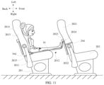
- FIG. 11 is a structural diagram of the seat support in FIG. 9 , and the seat support is fixed to front and back seats;
- FIG. 12 is a structural diagram of a seat support according to a fifth embodiment of the present disclosure.
- FIG. 13 is a structural diagram of a seat support according to a sixth embodiment of the present disclosure.
- FIG. 14 is a structural diagram of a seat support according to a seventh embodiment of the present disclosure.
- FIG. 15 is a structural diagram of a seat support according to an eight embodiment of the present disclosure.
- FIG. 16 is a structural diagram of a seat support according to a ninth embodiment of the present disclosure.
- FIG. 17 is a structural diagram of a seat support according to a tenth embodiment of the present disclosure.
- FIG. 18 is a structural diagram of an airbag of the seat support in FIG. 17 ;
- FIG. 19 is a structural diagram of a seat support according to an eleventh embodiment of the present disclosure.
- FIG. 20 is a structural diagram of an anti-skid portion and a support portion of the seat support in FIG. 1 .
- all of the directional instructions in the exemplary embodiments of the present disclosure can only be configured to explaining relative position relations, moving condition of the elements under a special form (referring to FIGS.), and so on, if the special form changes, the directional instructions change accordingly.
- the descriptions, such as the “first”, the “second” in the present disclosure, can only be configured to describing the aim of description, and cannot be understood as indicating or suggesting relative importance or impliedly indicating the number of the indicated technical character. Therefore, the character indicated by the “first”, the “second” can express or impliedly include at least one character.
- the technical proposal of each exemplary embodiment can be combined with each other, however the technical proposal must base on that the ordinary skill in that art can realize the technical proposal, when the combination of the technical proposals occurs contradiction or cannot realize, it should consider that the combination of the technical proposals does not exist, and is not contained in the protection scope required by the present disclosure.
- the present disclosure provides a seat support 100 a according to a first embodiment.
- the seat support 100 a includes a support member 1 a , a first connecting member 2 a and a second connecting member 3 a .
- the support member 1 a includes a support portion 11 a and an anti-skid portion 12 a .
- the support portion 11 a is a sheet, the support portion 11 a includes a back side 1101 a and a front side 1102 a , and the anti-skid portion 12 a is arranged on the back side of the support portion 11 a .
- the first connecting member 2 a is fixedly connected with a first end (i.e. a front end) of the support portion 11 a , and the first connecting member 2 a and the first end of the support member 1 a enclose a first connecting portion 101 a .
- the second connecting member 3 a is fixedly connected with a second end (i.e. a rear end) of the support portion 11 a , and the second connecting member 3 a and the second end enclose a second connecting portion 34 a .
- the anti-skid portion 12 a is an anti-skid layer arranged on the back side 1102 a , and the anti-skid layer 12 a is made of an anti-skid material, such as silicone, rubber, nylon, and woven materials with rough surfaces.
- the seat support 100 a is connected with the seats of a vehicle, such as a car, a bus, a high-speed train, an airplane, and the like.
- a part of the seat support 100 a is arranged on a seat cushion 2011 of the back seat assembly 201 and connected with a backrest 2013 of the back seat, and another part of the seat support 100 a is connected with the front seat assembly 202 .
- An area of the seat support 100 a between the seat cushion 2011 and the front seat assembly 202 is regarded as a suspension portion 2012 .
- User can sit on the seat cushion 2011 of the back seat assembly 201 , and place legs and foot on the suspension portion 2012 . In this way, user's legs are supported and the pressures on the legs are relieved.
- the anti-skid portion 12 a on the support member 1 a can increase a friction between the support member 1 a and the seat cushion 2011 . Even if user continuously adjusts his sitting postures, the support member 1 a can fit with the seat cushion 2011 orderly.
- the support portion 11 a is a sheet, that is, the support portion 11 a is thin, small in size and light in weight, so the seat support 100 a can be easily carried when traveling.
- the first connecting member 2 a is fixedly connected with the front seat assembly 202
- the second connecting member 3 a is fixedly connected with the back seat assembly 201 .
- the support member 1 a is firmly connected between the back seat assembly 201 and the front seat assembly 202 .
- the first connecting member 2 a and the second connecting member 3 a are both provided with an adjustment buckle (not labeled), lengths of the first connecting member 2 a and the second connecting member 3 a can be adjusted to adapt to seats with different sizes, so the support member 1 a is firmly connected between the back seat assembly 201 and the front seat assembly 202 .
- the first connecting member 2 a and the second connecting member 3 a can further be elastic, and the sizes of the first connecting member 2 a and the second connecting member 3 a can further be adjusted.
- the first connecting member 2 a includes a covering portion 211 a covering the support portion 11 a , and at least a part of the covering portion 211 a is not sewn with the support portion 11 a , or the covering portion 211 a is completely sewn with the support portion 11 a ; the covering portion 211 a passes through the support portion 11 a , and the covering portion 211 a is a one-piece structure.
- the support member 1 a is flatly laid between the front seat assembly 202 and back seat assembly 201 , and the first connecting member 2 a and the second connecting member 3 a are used to fix the support member 1 a .
- the first connecting member 2 a is fixedly connected with the front seat assembly 202
- the second connecting member 3 a is fixedly connected with the back seat assembly 201 .
- the support member 1 a can be stably arranged between the front seat assembly 202 and the back seat assembly 201
- the suspension portion 2012 of the support member 1 a can support user's feet and the legs, thereby alleviating the acid swellings and numbness of the feet and the legs.
- the anti-skid portion 12 a can increase the friction between the support portion 11 a and the seat cushion 2011 , so that the support portion 11 a will not move under a movement of user.
- the support portion 11 a is made of flexible material.
- the support portion 11 a includes an inner layer 111 a and a surface layer 112 a fixedly connected with the inner layer 111 a .
- the anti-skid portion 12 a is arranged on the inner layer 111 a and protruded from an outer surface of the inner layer 111 a .
- a periphery of the inner layer 111 a is fixedly connected with a periphery of the surface layer 112 a .
- areas of the inner layer 111 a except the periphery are not separated from areas of the surface layer 112 a except the periphery, that is, the inner layer 111 a is completely fixedly with the surface layer 112 a .
- at least a portion of areas of the inner layer 111 a except the periphery is fixedly connected with an area of the surface layer 112 a except the periphery, that is, the inner layer 111 a is not completely fixedly with the surface layer 112 a.
- the support portion 11 a is made of a flexible material.
- the support portion 11 a is preferably made of a breathable flexible material, so it's very breathable for the user's hip and feet.
- the support portion 11 a has a double-layer structure, which is convenient to increase the thickness of the support portion 11 a . So that, the user will not feel the presence of the anti-skid portion 12 a when sitting on the support portion 11 a . Further, it is further conducive to the setting of the anti-skid portion 12 a on the thick support portion 11 a .
- the plastic materials are usually injected onto the inner layer 111 a , and the inner layer 111 a is set thinner, which can facilitate the attachment of plastic materials. It should be understood that in order to further increase the comfort of the support portion 11 a , sponge or cotton can be filled between the inner layer 111 a and the surface layer 112 a.
- the inner layer 111 a is made of flexible material, such as cloth, fiber, paper cloth, polyurethane, PVC (Polyvinyl Chloride) flocking, etc.
- the periphery of the inner layer 111 a is fixedly connected with the periphery of the surface layer 112 a .
- the anti-skid portion 12 a is arranged on the outer surface of the inner layer 111 a .
- the inner layer 111 a is also fixedly connected to a middle portion of the surface layer 112 a.
- the anti-skid portion 12 a includes a plurality of anti-skid bumps 121 a , which are arranged on the outer surface of the inner layer 111 a .
- the anti-skid bump 121 a is made of plastic, silicone, or rubber.
- the anti-skid bumps 121 a are uniformly arranged on the back side; or the anti-skid bumps 121 a are randomly arranged on the back side.
- the anti-skid bump 121 a has a diameter of about 0-200 mm, for example, the anti-skid bump 121 a has a diameter of 0.1 mm, 1 mm, 2 mm, 3 mm, 4 mm, 5 mm, 10 mm, 50 mm, 100 mm, 150 mm, or 200 mm.
- the anti-skid bump 121 a has a height of about 0-20 mm, for example, the anti-skid bump 121 a has a height of 0.1 mm, 0.2 mm, 0.5 mm, 1 mm, 1.5 mm, 2 mm, 5 mm, 10 mm, 15 mm, or 20 mm
- a space between two adjacent anti-skid bumps 121 a is about 0-200 mm, for example, the space between two adjacent anti-skid bumps 121 a is 0.1 mm, 1 mm, 2 mm, 3 mm, 4 mm, 5 mm, 10 mm, 50 mm, 100 mm, 150 mm, or 200 mm.
- the anti-skid bumps 121 a are arranged in a plurality of bump groups, diameters of bumps in each bump groups gradually decrease or increase in a direction from the back seat assembly 201 to the front seat assembly 202 , or heights of bumps in each bump groups gradually decrease or increase in a direction from the back seat assembly 201 to the front seat assembly 202 .
- the cloth material has a good air permeability, and the anti-skid portion 12 a can be quickly bonded with the inner layer 111 a during injection molding.
- the anti-skid portion 12 a is set as a plurality of anti-skid bumps 121 a , so that user can hardly feel the presences of the anti-skid bumps 121 a even when he is sitting on the support portion 11 a.
- a thickness of the surface layer 112 a is greater than that of the inner layer 111 a .
- the thinner inner layer 111 a can facilitate a rapid prototyping of anti-skid bumps 121 a , and the thicker surface layer 112 a can reduce the presences of anti-skid bumps 121 a.
- the inner layer 111 a and the surface layer 112 a are made of flexible material, such as cloth, fiber, paper cloth, polyurethane, PVC (Polyvinyl Chloride) flocking, etc., and the periphery of the inner layer 111 a is sewn and fixedly connected with the periphery of the surface layer 112 a .
- the cloth has a good air permeability.
- Both the surface layer 112 a and the inner layer 111 a are made of cloth, so the surface layer 112 a and the inner layer 111 a can be easily stored, carried and cleaned.
- both the first connecting member 2 a and the second connecting member 3 a are fixedly connected with the outer surface of the surface layer 112 a of the support portion 11 a , to prevent the first connecting member 2 a and the second connecting member 2 a from affecting the arrangement of the anti-skid portion 12 a .
- the first connecting member 2 a or the second connecting member 3 a can also be arranged on an inner surface of the surface layer 112 a or an inner surface of the inner layer 111 a .
- the first connecting member 2 a or the second connecting member 3 a can also be arranged on an outer surface of the inner layer 111 a.
- the first connecting member 2 a includes a connecting belt 21 a (which can be a long mesh belt), a connecting part 22 a (which can be a clamping seat), and a connecting part 23 a (which can be a clamping head).
- a middle section of the connecting belt 21 a is fixedly connected with the support portion 11 a , and both ends of the connecting belt 21 a extend outside the support portion 11 a .
- One end of the connecting belt 21 a is connected with the connecting part 22 a , the other end is connected with the connecting part 23 a .
- the connecting belt 21 a When the connecting part 22 a is detachably connected with the connecting part 23 a , the connecting belt 21 a , the connecting part 22 a , the connecting part 23 a , the support portion 11 a enclose the connecting portion 24 a .
- the connecting belt 21 a may be connected with the inner layer 111 a or the surface layer 112 a or connected between the inner layer 111 a and the surface layer 112 a.
- the second connecting member 3 a includes two connecting belts 31 a (which can be medium length mesh belt), a connecting part 32 a (which can be a clamping seat) and a connecting part 33 a (which can be a clamping head).
- One end of the connecting belt 31 a is fixedly connected with a corner at the first end of the support portion 11 a , and the other end extends out of the support portion 11 a .
- One of the two connecting belts 31 a is fixedly connected with the connecting part 32 a , the other one is fixedly connected with the connecting part 33 a .
- the connecting part 22 a is clamped with the connecting part 23 a to form a ring shaped connecting portion 24 a .
- the ring shaped connecting portion 24 a sleeves on the backrest 2021 of the front seat assembly 202 (see FIG. 4 ), or sleeves on a table 2022 arranged on the front seat assembly 202 (see FIG. 5 ), or sleeves on a connecting element 2023 which is configured to connect the table 2022 with the backrest 2021 .
- both ends of the connecting belt 21 a can pass the backrest 2021 of the front seat assembly 202 from both sides, and then the connecting part 22 a is clamped in the connecting part 23 a , so that the seat support 100 a can be connected with the front seat assembly 202 rapidly.
- the two second connecting belts 31 a may be asymmetrically connected with the support portion 11 a , so that seat support 100 a has a high the fault tolerance.
- the second connecting belts 31 a form an annular second connecting portion 34 a by connecting the connecting part 32 a with the connecting part 33 a .
- the second connecting portion 34 a can sleeve on the back seat assembly 201 , to connect the seat support 100 a with the back seat assembly 201 .
- the second connecting portion may be installed in the same way as the first connecting portion, so it will not be described here.
- connecting belt 21 a and the connecting belt 31 a are fixedly connected with the support portion 11 a by sewing. In this way, the connecting belt 21 a and the connecting belt 31 a are relatively stably connected with the support portion 11 a .
- the connecting part 22 a is adapted to the connecting part 23 a , and can be connected and matched with each other. This connection mode is simple and reliable, and is convenient for users to operate.
- the present disclosure provides a seat support 100 b according to a second embodiment.
- the seat support 100 b is similar to the seat support 100 a in structure, and the differences between the two at least include: the first connecting member 2 b is an elastic belt 21 b , two ends of the elastic belt 21 b are fixedly connected with two corners of the first end of the support portion 11 a , and the elastic belt 21 b and the support portion 11 a enclose the connecting portion 24 b.
- the two ends of the elastic belt 21 b are fixedly connected with the support portion 11 b to forms the annular connecting portion 24 b which can sleeve on the front seat assembly 202 .
- the second connecting member 3 b is similar with the second connecting member 3 a in structure.
- the present disclosure provides a seat support 100 c according to a third embodiment.
- the seat support 100 c is similar to the seat support 100 a in structure, and the differences between the two at least include: the second connecting member 3 c includes two connecting belts 31 c (which can be short mesh belts), both ends of each connecting belt 31 c are fixedly connected with the support portion 11 c , and a middle portion of each connecting belt 31 c is separated from the support portion 11 c to form a connecting portion 34 c for the safety belt to pass through;
- the first connecting member 2 c includes two connecting belts 21 c (which can be short mesh belts), a connecting belt 22 c (which can be a mesh belt with a medium length), two connecting parts 23 c (which can be clamping seats), and two connecting parts 24 c (which can be clamping heads); ends of the two connecting belts 21 c are fixedly connected with two corners of the second end of the support portion 11 c , other ends of the two connecting belts 21
- the second connecting member 3 c is the same as the second connecting member 3 e , the first connecting member 2 a , or the second connecting member 3 b.
- the present disclosure provides a seat support 100 d according to a fourth embodiment.
- the seat support 100 d is similar to the seat support 100 c in structure, and the differences between the two at least include: the first connecting member 2 d includes two connecting belts 21 d (which can be short mesh belts) and two connecting parts 22 d (which can be locking hooks, hangers, etc.); end of the two connecting belt 21 d are fixed at two corners of the first end of the support portion 11 d , the other ends of the two connecting belts 21 d are respectively fixedly connected with the connecting parts 22 d.
- the first connecting member 2 d includes two connecting belts 21 d (which can be short mesh belts) and two connecting parts 22 d (which can be locking hooks, hangers, etc.); end of the two connecting belt 21 d are fixed at two corners of the first end of the support portion 11 d , the other ends of the two connecting belts 21 d are respectively fixedly connected with the connecting parts 22 d.
- the connecting parts 22 d can be connected with the connecting element 2023 arranged on the backrest 2021 of the front seat assembly 202 or connected with buckles 2024 of the front seat assembly 202 arranged on the backrest 2021 , the buckles 2024 of the front seat assembly 202 are used for hanging luggage, so that the first end of the seat support 100 d can be fixed on the front seat assembly 202 .
- the two connecting parts 22 d may also be connected to each other to form a connecting portion 24 d which is configured to connect with the table 2022 of the front seat assembly 202 .
- the connecting parts 22 d can be connected with the buckles 2015 arranged on two sides of the backrest 2013 , to connect the seat support 100 d with the back seat assembly 201 .
- the connecting parts 22 d are fixed in the gap between the backrest 2013 and the seat cushion 2011 , to connect the seat support 100 d with the back seat assembly 201 .
- the second connecting member 3 d is similar as the second connecting member 3 c in structure.
- the present disclosure provides a seat support 100 e according to a fifth embodiment.
- the seat support 100 e is similar to the seat support 100 a in structure, and the differences between the two at least include: the connecting belt 31 e of the second connecting member 3 e includes a covering portion 311 e covering the support portion 11 e , and at least a part of the covering portion 311 e is not sewn with the support portion 11 e to form the connecting portion 35 e ; the covering portion 311 e pass through the support portion 11 e along a radial direction of the support portion 11 e .
- the covering portion 311 e is a one-piece structure.
- two portions of the covering portion 311 e are not sewn with the support portion 11 e to form two connection portions 35 e spaced at intervals.
- the safety belts 2016 of the back seat assembly 201 can pass through the two connecting portions 35 e respectively, and then user fixes the safety belts 2016 . In this way, the two connecting members 3 e can further be fixed.
- the connecting member 2 e is similar with the connecting member 3 a in structure.
- the present disclosure provides a seat support 100 f according to a sixth embodiment.
- the seat support 100 f is similar to the seat support 100 c in structure, and the differences between the two at least include: the second connecting member 3 f includes two connecting belts 31 f and an elastic belt 32 f , and both ends of the elastic belt 32 f are respectively connected with both ends of the support portion 11 f to form the connecting portion 34 f which can sleeve on the backrest 2013 ; both ends of the connecting belt 31 f are connected with the support portion 11 f to form the connecting portion 35 f for the safety belt to pass through.
- the suturing portion of the elastic belt 32 f and the support portion 11 f at least partially coincides with the suturing portion of the connecting belt 31 f and the support portion 11 f.
- the connecting member 2 f is similar with the connecting member 3 d in structure.
- the present disclosure provides a seat support 100 g according to a seventh embodiment.
- the seat support 100 g is similar to the seat support 100 b in structure, and the differences between the two at least include: the seat support 100 g further includes a first sub support 1011 g and a second sub support 1012 g connected with the first sub support 1011 g ; the first sub support 1011 g is arranged on the seat cushion 2011 of the back seat assembly 201 , the second sub support 1012 g is connected with the front seat assembly 202 and the first sub support 1011 g to form the suspension portion 2012 for supporting the legs and feet;
- the second connecting member 3 g includes at least one connecting belt 31 g and at least one clamping part 32 g ; the connecting belt 31 g is connected with the first sub support 1011 g and extends out of the first sub support 1011 g ; the clamping part 32 g is connected with the portion of the connecting belt 31 g and extended out of the first sub support 1011 g , the clamping part
- the first sub support 1011 g and the second sub support 1012 g may be made of different or same materials.
- a width of the second sub support 1012 g can be greater than that of the first sub support 1011 g to support the user's legs well.
- the second sub support 1012 g is protruded with two connecting protrusions 120 g , and two connection belts 21 g are respectively connected with two connecting protrusions 120 g.
- the present disclosure provides a seat support 100 h according to an eighth embodiment.
- the seat support 100 h is similar to the seat support 100 b in structure, and the differences between the two at least include: the support portion 11 h includes two convex portions 113 h and two recessed portions 114 h , the second connecting member 3 h includes two connecting belts 31 h , a connecting part 32 h and a connecting part 33 h , and the two connecting belts 31 h are connected by the connecting part 32 h and the connecting part 33 h ; one end of the connecting belt 31 h is connected with the convex portion 113 h , the connecting belt 31 h and the recessed portion 114 cooperatively form a connecting portion 313 h to connect with the safe belt, in detail, the safety belt can pass through the connecting portion 313 h ; the second connecting member 3 h further includes two connecting belts 36 h for connecting the connecting belt 31 h with the support portion 11 h ; the connecting belt 31 h , the
- the first connecting member 2 h is similar with the first connecting member 2 b in structure.
- the present disclosure provides a seat support 100 i according to a ninth embodiment.
- the seat support 100 i is similar to the seat support 100 b in structure, and the differences between the two at least include: the support portion 11 i includes a sleeving portion 115 i configured to sleeve on the backrest 2013 of the back seat assembly 201 ; the second connecting member 3 i further includes two connecting belts 37 i protruded from both ends of the support portion 11 i respectively, a free end of the connecting belt 37 i is provided with a connecting ring 371 i configured to connect with a hook 2014 arranged on the back seat assembly 201 ; the connecting belt 31 i is positioned between the connecting belt 37 i and an opening of the sleeving portion 115 i ; the connecting belt 31 i is provided with a clamping ring 311 i , and the clamping ring 311 i is detachably clamped with a connecting ring 312 i connected with the connecting
- the first connecting member 2 i sleeves on the back seat assembly 201 , the connecting parts 39 i are connected with the safety belts 2016 or buckles 2015 on the backrest 2013 , the connecting belts 31 i are connected with the front seat assembly 202 , the sleeving portion 115 i may be used as a pocket.
- the first connecting member 2 i can sleeve the back seat assembly 201 .
- the first connecting member 2 i is similar with the first connecting member 2 b in structure.
- the present disclosure provides a seat support 100 j according to a tenth embodiment.
- the seat support 100 j is similar to the seat support 100 b in structure, and the differences between the two at least include: the seat support 100 j does not include a second connecting member, and the first connecting member 2 j is connected with the front seat assembly 202 ; the supporting member 11 i has a receiving cavity 116 j , the receiving cavity 116 j is defined between inner layer 111 j and the surface layer 112 j and used to receive an airbag 117 j , and the airbag 117 j is provided with an air charging and discharging part 118 j for inflating and deflating the airbag 117 j.
- the support portion 11 i further includes an airbag 117 j , when the support portion 11 i and airbag 117 i are placed on the seat cushion 2011 of the back seat assembly 201 , the support portion 11 i and airbag 117 i can be stably placed on the seat cushion 2011 by their own gravity. In addition, user can further fix the support portion 11 i and airbag 117 j when sitting on the support portion 11 i and airbag 117 j.
- the present disclosure provides a seat support 100 k according to an eleventh embodiment.
- the seat support 100 k is similar to the seat support 100 c in structure, and the differences between the two at least include: the second connecting assembly 3 k includes two connecting belts 31 k , a connecting part 32 k , and a connecting part 33 k , the connecting belts 31 k are connected with each other by the connecting part 32 k and the connecting part 33 k.
Landscapes
- Engineering & Computer Science (AREA)
- Aviation & Aerospace Engineering (AREA)
- Transportation (AREA)
- Mechanical Engineering (AREA)
- Seats For Vehicles (AREA)
- Mattresses And Other Support Structures For Chairs And Beds (AREA)
Abstract
The present disclosure provides a seat support applied to a vehicle, the vehicle has a front seat assembly and a back seat assembly. The seat support includes a support member and a first connecting member. The support member includes a support portion arranged on the back seat assembly, and an anti-skid portion arranged on the support portion. The first connecting member is arranged on the support portion and configured to connect the support portion with the front seat assembly.
Description
The present application claims the benefit of Chinese Patent Application No. 202222494353.4 filed on Sep. 20, 2022, the contents of which are incorporated herein by reference in their entirety.
This present disclosure relates to supports, and in particular to a seat support for use in conjunction with seats during travel.
Travelling has become a very common part of life. People often travel for long periods during which time they are seated in a chair and are generally sedentary. In particular, travelling in airplanes requires a passenger to be seated in a cramped position for many hours; travelling in trains, buses and the like can further see a passenger seated for long periods of time in awkward and uncomfortable positions.
Sitting for long periods can become very uncomfortable and can lead to tired and aching muscles, swollen legs, deep vein thrombosis (DVT) and even the life threatening condition of pulmonary emboli. Furthermore, it can be difficult to sleep in an upright seated position and travelers can often become sleep deprived. All of these factors make travelling for long periods uncomfortable.
Accordingly, it would be advantageous of the present disclosure to provide a technical solution which ameliorates one or more of the disadvantages set forth above or at least provide the public with a useful choice.
The present disclosure provides a seat support applied to a vehicle, the vehicle has a front seat assembly and a back seat assembly. The seat support includes a support member and a first connecting member. The support member includes a support portion arranged on the back seat assembly, and an anti-skid portion arranged on the support portion. The first connecting member is arranged on the support portion and configured to connect the support portion with the front seat assembly.
The present disclosure provides another seat support applied to a vehicle, the vehicle has a front seat assembly and a back seat assembly. The seat support includes a support member, a first connecting member, and a second connecting member. The support member includes a support portion arranged on the back seat assembly. The first connecting member is arranged on the support portion and configured to connect the support portion with the front seat assembly. The second connecting member is arranged on the support portion and configured to connect the support portion with the back seat assembly.
Implementations of the present disclosure will now be described, by way of embodiment, with reference to the attached FIGS. It should be understood, the drawings are shown for illustrative purpose only, for ordinary person skilled in the art, other drawings obtained from these drawings without paying creative labor by an ordinary person skilled in the art should be within scope of the present disclosure.
The realization of the aim, functional characteristics, advantages of the present disclosure are further described specifically with reference to the accompanying drawings and embodiments.
The technical solutions of the embodiments of the present disclosure will be clearly and completely described in the following with reference to the accompanying drawings. It is obvious that the embodiments to be described are only a part rather than all of the embodiments of the present disclosure. All other embodiments obtained by persons skilled in the art based on the embodiments of the present invention without creative efforts shall fall within the protection scope of the present invention.
It is to be understood that, all of the directional instructions in the exemplary embodiments of the present disclosure (such as top, down, left, right, front, back) can only be configured to explaining relative position relations, moving condition of the elements under a special form (referring to FIGS.), and so on, if the special form changes, the directional instructions change accordingly.
In addition, the descriptions, such as the “first”, the “second” in the present disclosure, can only be configured to describing the aim of description, and cannot be understood as indicating or suggesting relative importance or impliedly indicating the number of the indicated technical character. Therefore, the character indicated by the “first”, the “second” can express or impliedly include at least one character. In addition, the technical proposal of each exemplary embodiment can be combined with each other, however the technical proposal must base on that the ordinary skill in that art can realize the technical proposal, when the combination of the technical proposals occurs contradiction or cannot realize, it should consider that the combination of the technical proposals does not exist, and is not contained in the protection scope required by the present disclosure.
Referring to FIGS. 1-5 and 20 , the present disclosure provides a seat support 100 a according to a first embodiment.
The seat support 100 a includes a support member 1 a, a first connecting member 2 a and a second connecting member 3 a. The support member 1 a includes a support portion 11 a and an anti-skid portion 12 a. The support portion 11 a is a sheet, the support portion 11 a includes a back side 1101 a and a front side 1102 a, and the anti-skid portion 12 a is arranged on the back side of the support portion 11 a. The first connecting member 2 a is fixedly connected with a first end (i.e. a front end) of the support portion 11 a, and the first connecting member 2 a and the first end of the support member 1 a enclose a first connecting portion 101 a. The second connecting member 3 a is fixedly connected with a second end (i.e. a rear end) of the support portion 11 a, and the second connecting member 3 a and the second end enclose a second connecting portion 34 a. In an embodiment, the anti-skid portion 12 a is an anti-skid layer arranged on the back side 1102 a, and the anti-skid layer 12 a is made of an anti-skid material, such as silicone, rubber, nylon, and woven materials with rough surfaces.
The seat support 100 a is connected with the seats of a vehicle, such as a car, a bus, a high-speed train, an airplane, and the like. A part of the seat support 100 a is arranged on a seat cushion 2011 of the back seat assembly 201 and connected with a backrest 2013 of the back seat, and another part of the seat support 100 a is connected with the front seat assembly 202. An area of the seat support 100 a between the seat cushion 2011 and the front seat assembly 202 is regarded as a suspension portion 2012. User can sit on the seat cushion 2011 of the back seat assembly 201, and place legs and foot on the suspension portion 2012. In this way, user's legs are supported and the pressures on the legs are relieved. The anti-skid portion 12 a on the support member 1 a can increase a friction between the support member 1 a and the seat cushion 2011. Even if user continuously adjusts his sitting postures, the support member 1 a can fit with the seat cushion 2011 orderly. The support portion 11 a is a sheet, that is, the support portion 11 a is thin, small in size and light in weight, so the seat support 100 a can be easily carried when traveling.
Specifically, the first connecting member 2 a is fixedly connected with the front seat assembly 202, and the second connecting member 3 a is fixedly connected with the back seat assembly 201. In this way, the support member 1 a is firmly connected between the back seat assembly 201 and the front seat assembly 202. It should be understood that the first connecting member 2 a and the second connecting member 3 a are both provided with an adjustment buckle (not labeled), lengths of the first connecting member 2 a and the second connecting member 3 a can be adjusted to adapt to seats with different sizes, so the support member 1 a is firmly connected between the back seat assembly 201 and the front seat assembly 202. Of course, the first connecting member 2 a and the second connecting member 3 a can further be elastic, and the sizes of the first connecting member 2 a and the second connecting member 3 a can further be adjusted.
The first connecting member 2 a includes a covering portion 211 a covering the support portion 11 a, and at least a part of the covering portion 211 a is not sewn with the support portion 11 a, or the covering portion 211 a is completely sewn with the support portion 11 a; the covering portion 211 a passes through the support portion 11 a, and the covering portion 211 a is a one-piece structure.
The support member 1 a is flatly laid between the front seat assembly 202 and back seat assembly 201, and the first connecting member 2 a and the second connecting member 3 a are used to fix the support member 1 a. The first connecting member 2 a is fixedly connected with the front seat assembly 202, and the second connecting member 3 a is fixedly connected with the back seat assembly 201. In this way, the support member 1 a can be stably arranged between the front seat assembly 202 and the back seat assembly 201, and the suspension portion 2012 of the support member 1 a can support user's feet and the legs, thereby alleviating the acid swellings and numbness of the feet and the legs. The anti-skid portion 12 a can increase the friction between the support portion 11 a and the seat cushion 2011, so that the support portion 11 a will not move under a movement of user.
Further, referring to FIGS. 1-2 , the support portion 11 a is made of flexible material. The support portion 11 a includes an inner layer 111 a and a surface layer 112 a fixedly connected with the inner layer 111 a. The anti-skid portion 12 a is arranged on the inner layer 111 a and protruded from an outer surface of the inner layer 111 a. Specifically, a periphery of the inner layer 111 a is fixedly connected with a periphery of the surface layer 112 a. In one embodiment, areas of the inner layer 111 a except the periphery are not separated from areas of the surface layer 112 a except the periphery, that is, the inner layer 111 a is completely fixedly with the surface layer 112 a. In another embodiment, at least a portion of areas of the inner layer 111 a except the periphery is fixedly connected with an area of the surface layer 112 a except the periphery, that is, the inner layer 111 a is not completely fixedly with the surface layer 112 a.
In order to facilitate the storage and enhance user comfort, the support portion 11 a is made of a flexible material. The support portion 11 a is preferably made of a breathable flexible material, so it's very breathable for the user's hip and feet. The support portion 11 a has a double-layer structure, which is convenient to increase the thickness of the support portion 11 a. So that, the user will not feel the presence of the anti-skid portion 12 a when sitting on the support portion 11 a. Further, it is further conducive to the setting of the anti-skid portion 12 a on the thick support portion 11 a. When the anti-skid portion 12 a is made of plastic materials, the plastic materials are usually injected onto the inner layer 111 a, and the inner layer 111 a is set thinner, which can facilitate the attachment of plastic materials. It should be understood that in order to further increase the comfort of the support portion 11 a, sponge or cotton can be filled between the inner layer 111 a and the surface layer 112 a.
Further, please referring to FIG. 2 , the inner layer 111 a is made of flexible material, such as cloth, fiber, paper cloth, polyurethane, PVC (Polyvinyl Chloride) flocking, etc. The periphery of the inner layer 111 a is fixedly connected with the periphery of the surface layer 112 a. The anti-skid portion 12 a is arranged on the outer surface of the inner layer 111 a. The inner layer 111 a is also fixedly connected to a middle portion of the surface layer 112 a.
The anti-skid portion 12 a includes a plurality of anti-skid bumps 121 a, which are arranged on the outer surface of the inner layer 111 a. The anti-skid bump 121 a is made of plastic, silicone, or rubber. The anti-skid bumps 121 a are uniformly arranged on the back side; or the anti-skid bumps 121 a are randomly arranged on the back side. The anti-skid bump 121 a has a diameter of about 0-200 mm, for example, the anti-skid bump 121 a has a diameter of 0.1 mm, 1 mm, 2 mm, 3 mm, 4 mm, 5 mm, 10 mm, 50 mm, 100 mm, 150 mm, or 200 mm. The anti-skid bump 121 a has a height of about 0-20 mm, for example, the anti-skid bump 121 a has a height of 0.1 mm, 0.2 mm, 0.5 mm, 1 mm, 1.5 mm, 2 mm, 5 mm, 10 mm, 15 mm, or 20 mm A space between two adjacent anti-skid bumps 121 a is about 0-200 mm, for example, the space between two adjacent anti-skid bumps 121 a is 0.1 mm, 1 mm, 2 mm, 3 mm, 4 mm, 5 mm, 10 mm, 50 mm, 100 mm, 150 mm, or 200 mm. The anti-skid bumps 121 a are arranged in a plurality of bump groups, diameters of bumps in each bump groups gradually decrease or increase in a direction from the back seat assembly 201 to the front seat assembly 202, or heights of bumps in each bump groups gradually decrease or increase in a direction from the back seat assembly 201 to the front seat assembly 202.
The cloth material has a good air permeability, and the anti-skid portion 12 a can be quickly bonded with the inner layer 111 a during injection molding. In order to ensure that the anti-skid portion 12 a will not affect the comfort of the seat support 100 a, the anti-skid portion 12 a is set as a plurality of anti-skid bumps 121 a, so that user can hardly feel the presences of the anti-skid bumps 121 a even when he is sitting on the support portion 11 a.
Further, a thickness of the surface layer 112 a is greater than that of the inner layer 111 a. The thinner inner layer 111 a can facilitate a rapid prototyping of anti-skid bumps 121 a, and the thicker surface layer 112 a can reduce the presences of anti-skid bumps 121 a.
Further, the inner layer 111 a and the surface layer 112 a are made of flexible material, such as cloth, fiber, paper cloth, polyurethane, PVC (Polyvinyl Chloride) flocking, etc., and the periphery of the inner layer 111 a is sewn and fixedly connected with the periphery of the surface layer 112 a. The cloth has a good air permeability. Both the surface layer 112 a and the inner layer 111 a are made of cloth, so the surface layer 112 a and the inner layer 111 a can be easily stored, carried and cleaned.
Further, both the first connecting member 2 a and the second connecting member 3 a are fixedly connected with the outer surface of the surface layer 112 a of the support portion 11 a, to prevent the first connecting member 2 a and the second connecting member 2 a from affecting the arrangement of the anti-skid portion 12 a. In another embodiment, the first connecting member 2 a or the second connecting member 3 a can also be arranged on an inner surface of the surface layer 112 a or an inner surface of the inner layer 111 a. In a further embodiment, the first connecting member 2 a or the second connecting member 3 a can also be arranged on an outer surface of the inner layer 111 a.
Further, referring to FIGS. 1 and 2 , the first connecting member 2 a includes a connecting belt 21 a (which can be a long mesh belt), a connecting part 22 a (which can be a clamping seat), and a connecting part 23 a (which can be a clamping head). A middle section of the connecting belt 21 a is fixedly connected with the support portion 11 a, and both ends of the connecting belt 21 a extend outside the support portion 11 a. One end of the connecting belt 21 a is connected with the connecting part 22 a, the other end is connected with the connecting part 23 a. When the connecting part 22 a is detachably connected with the connecting part 23 a, the connecting belt 21 a, the connecting part 22 a, the connecting part 23 a, the support portion 11 a enclose the connecting portion 24 a. The connecting belt 21 a may be connected with the inner layer 111 a or the surface layer 112 a or connected between the inner layer 111 a and the surface layer 112 a.
The second connecting member 3 a includes two connecting belts 31 a (which can be medium length mesh belt), a connecting part 32 a (which can be a clamping seat) and a connecting part 33 a (which can be a clamping head). One end of the connecting belt 31 a is fixedly connected with a corner at the first end of the support portion 11 a, and the other end extends out of the support portion 11 a. One of the two connecting belts 31 a is fixedly connected with the connecting part 32 a, the other one is fixedly connected with the connecting part 33 a. When the connecting part 32 a is clamped with the connecting part 33 a, the two connecting belts 31 a, the connecting part 32 a, the connecting part 33 a and the support portion 11 a enclose the second connecting portion 34 a.
The connecting part 22 a is clamped with the connecting part 23 a to form a ring shaped connecting portion 24 a. The ring shaped connecting portion 24 a sleeves on the backrest 2021 of the front seat assembly 202 (see FIG. 4 ), or sleeves on a table 2022 arranged on the front seat assembly 202 (see FIG. 5 ), or sleeves on a connecting element 2023 which is configured to connect the table 2022 with the backrest 2021. In addition, both ends of the connecting belt 21 a can pass the backrest 2021 of the front seat assembly 202 from both sides, and then the connecting part 22 a is clamped in the connecting part 23 a, so that the seat support 100 a can be connected with the front seat assembly 202 rapidly. The two second connecting belts 31 a may be asymmetrically connected with the support portion 11 a, so that seat support 100 a has a high the fault tolerance. The second connecting belts 31 a form an annular second connecting portion 34 a by connecting the connecting part 32 a with the connecting part 33 a. The second connecting portion 34 a can sleeve on the back seat assembly 201, to connect the seat support 100 a with the back seat assembly 201. The second connecting portion may be installed in the same way as the first connecting portion, so it will not be described here.
It should be understood that the connecting belt 21 a and the connecting belt 31 a are fixedly connected with the support portion 11 a by sewing. In this way, the connecting belt 21 a and the connecting belt 31 a are relatively stably connected with the support portion 11 a. It should be understood that the connecting part 22 a is adapted to the connecting part 23 a, and can be connected and matched with each other. This connection mode is simple and reliable, and is convenient for users to operate.
Referring to FIG. 6 , the present disclosure provides a seat support 100 b according to a second embodiment. The seat support 100 b is similar to the seat support 100 a in structure, and the differences between the two at least include: the first connecting member 2 b is an elastic belt 21 b, two ends of the elastic belt 21 b are fixedly connected with two corners of the first end of the support portion 11 a, and the elastic belt 21 b and the support portion 11 a enclose the connecting portion 24 b.
User can adjust the length of the elastic belt 21 b more quickly than the adjusting buckle. The two ends of the elastic belt 21 b are fixedly connected with the support portion 11 b to forms the annular connecting portion 24 b which can sleeve on the front seat assembly 202.
The second connecting member 3 b is similar with the second connecting member 3 a in structure.
Referring to FIGS. 7-8 , the present disclosure provides a seat support 100 c according to a third embodiment. The seat support 100 c is similar to the seat support 100 a in structure, and the differences between the two at least include: the second connecting member 3 c includes two connecting belts 31 c (which can be short mesh belts), both ends of each connecting belt 31 c are fixedly connected with the support portion 11 c, and a middle portion of each connecting belt 31 c is separated from the support portion 11 c to form a connecting portion 34 c for the safety belt to pass through; the first connecting member 2 c includes two connecting belts 21 c (which can be short mesh belts), a connecting belt 22 c (which can be a mesh belt with a medium length), two connecting parts 23 c (which can be clamping seats), and two connecting parts 24 c (which can be clamping heads); ends of the two connecting belts 21 c are fixedly connected with two corners of the second end of the support portion 11 c, other ends of the two connecting belts 21 c bently extend out of the support portion 11 c and connect with the two connecting parts 23 c respectively; both ends of the connecting belt 22 c are respectively connected with two connecting parts 24 c; the connecting parts 23 c are clamped with the connecting parts 24 c; two connecting belts 21 c, the connecting belt 22 c, the connecting parts 23 c, the connecting parts 24 c, and the support portion 11 c form the connecting portion 25 c which can sleeve on the backrest 2021 of the front seat assembly 202 or connected with the table 2022 of front seat assembly 202; ends of the two connecting belts 31 c are fixed on the support portion 11 c, and the two connecting belts 31 c and the support portion 11 c cooperatively form the connecting portions 34 c; the safety belts of the back seat assembly 201 can pass through the two connecting portions 34 c respectively, and then user fixes the safety belts, so that the second connecting member 3 c can further be fixed.
In another embodiment, the second connecting member 3 c is the same as the second connecting member 3 e, the first connecting member 2 a, or the second connecting member 3 b.
Referring to FIGS. 9-11 , the present disclosure provides a seat support 100 d according to a fourth embodiment. The seat support 100 d is similar to the seat support 100 c in structure, and the differences between the two at least include: the first connecting member 2 d includes two connecting belts 21 d (which can be short mesh belts) and two connecting parts 22 d (which can be locking hooks, hangers, etc.); end of the two connecting belt 21 d are fixed at two corners of the first end of the support portion 11 d, the other ends of the two connecting belts 21 d are respectively fixedly connected with the connecting parts 22 d.
The connecting parts 22 d can be connected with the connecting element 2023 arranged on the backrest 2021 of the front seat assembly 202 or connected with buckles 2024 of the front seat assembly 202 arranged on the backrest 2021, the buckles 2024 of the front seat assembly 202 are used for hanging luggage, so that the first end of the seat support 100 d can be fixed on the front seat assembly 202. It should be understood that the two connecting parts 22 d may also be connected to each other to form a connecting portion 24 d which is configured to connect with the table 2022 of the front seat assembly 202.
In an embodiment, the connecting parts 22 d can be connected with the buckles 2015 arranged on two sides of the backrest 2013, to connect the seat support 100 d with the back seat assembly 201. In another embodiment, the connecting parts 22 d are fixed in the gap between the backrest 2013 and the seat cushion 2011, to connect the seat support 100 d with the back seat assembly 201.
The second connecting member 3 d is similar as the second connecting member 3 c in structure.
Referring to FIG. 12 , the present disclosure provides a seat support 100 e according to a fifth embodiment. The seat support 100 e is similar to the seat support 100 a in structure, and the differences between the two at least include: the connecting belt 31 e of the second connecting member 3 e includes a covering portion 311 e covering the support portion 11 e, and at least a part of the covering portion 311 e is not sewn with the support portion 11 e to form the connecting portion 35 e; the covering portion 311 e pass through the support portion 11 e along a radial direction of the support portion 11 e. The covering portion 311 e is a one-piece structure.
In an embodiment, two portions of the covering portion 311 e are not sewn with the support portion 11 e to form two connection portions 35 e spaced at intervals.
The safety belts 2016 of the back seat assembly 201 can pass through the two connecting portions 35 e respectively, and then user fixes the safety belts 2016. In this way, the two connecting members 3 e can further be fixed.
The connecting member 2 e is similar with the connecting member 3 a in structure.
Referring to FIG. 13 , the present disclosure provides a seat support 100 f according to a sixth embodiment. The seat support 100 f is similar to the seat support 100 c in structure, and the differences between the two at least include: the second connecting member 3 f includes two connecting belts 31 f and an elastic belt 32 f, and both ends of the elastic belt 32 f are respectively connected with both ends of the support portion 11 f to form the connecting portion 34 f which can sleeve on the backrest 2013; both ends of the connecting belt 31 f are connected with the support portion 11 f to form the connecting portion 35 f for the safety belt to pass through.
The suturing portion of the elastic belt 32 f and the support portion 11 f at least partially coincides with the suturing portion of the connecting belt 31 f and the support portion 11 f.
The connecting member 2 f is similar with the connecting member 3 d in structure.
Please referring to FIG. 14 , the present disclosure provides a seat support 100 g according to a seventh embodiment. The seat support 100 g is similar to the seat support 100 b in structure, and the differences between the two at least include: the seat support 100 g further includes a first sub support 1011 g and a second sub support 1012 g connected with the first sub support 1011 g; the first sub support 1011 g is arranged on the seat cushion 2011 of the back seat assembly 201, the second sub support 1012 g is connected with the front seat assembly 202 and the first sub support 1011 g to form the suspension portion 2012 for supporting the legs and feet; the second connecting member 3 g includes at least one connecting belt 31 g and at least one clamping part 32 g; the connecting belt 31 g is connected with the first sub support 1011 g and extends out of the first sub support 1011 g; the clamping part 32 g is connected with the portion of the connecting belt 31 g and extended out of the first sub support 1011 g, the clamping part 32 g may be round in shape or have other suitable shape; the clamping part 32 g can be clamped in a gap between the seat cushion 2011 of the back seat assembly 201 and the backrest 2013 of the back seat assembly 201 to fix the first sub support 1011 g; the seat support 100 g further includes two opposite connecting belts 21 g, a connecting part 22 g (which may be a clamping seat) and a connecting part 23 g (which may be a clamping head), the connecting part 22 g and the connecting part 23 g are respectively connected with the free ends of the two connecting belts 21 g, the connecting belts 21 g, the connecting part 22 g, the connecting part 23 g and the second sub support 1012 g cooperatively form the connecting portion 24 g, the connecting portion 24 g sleeves on the front seat assembly 202; the second sub support 1012 g is further provided with a gas charging and discharging member 4 g to charge and discharge the second sub support 1012 g.
The first sub support 1011 g and the second sub support 1012 g may be made of different or same materials. A width of the second sub support 1012 g can be greater than that of the first sub support 1011 g to support the user's legs well.
The second sub support 1012 g is protruded with two connecting protrusions 120 g, and two connection belts 21 g are respectively connected with two connecting protrusions 120 g.
Referring to FIG. 15 , the present disclosure provides a seat support 100 h according to an eighth embodiment. The seat support 100 h is similar to the seat support 100 b in structure, and the differences between the two at least include: the support portion 11 h includes two convex portions 113 h and two recessed portions 114 h, the second connecting member 3 h includes two connecting belts 31 h, a connecting part 32 h and a connecting part 33 h, and the two connecting belts 31 h are connected by the connecting part 32 h and the connecting part 33 h; one end of the connecting belt 31 h is connected with the convex portion 113 h, the connecting belt 31 h and the recessed portion 114 cooperatively form a connecting portion 313 h to connect with the safe belt, in detail, the safety belt can pass through the connecting portion 313 h; the second connecting member 3 h further includes two connecting belts 36 h for connecting the connecting belt 31 h with the support portion 11 h; the connecting belt 31 h, the connecting belt 36 h, the connecting part 32 h, the connecting part 33 h, and the support portion 11 h form the connecting portion 34 h.
The first connecting member 2 h is similar with the first connecting member 2 b in structure.
Please referring to FIG. 16 . the present disclosure provides a seat support 100 i according to a ninth embodiment. The seat support 100 i is similar to the seat support 100 b in structure, and the differences between the two at least include: the support portion 11 i includes a sleeving portion 115 i configured to sleeve on the backrest 2013 of the back seat assembly 201; the second connecting member 3 i further includes two connecting belts 37 i protruded from both ends of the support portion 11 i respectively, a free end of the connecting belt 37 i is provided with a connecting ring 371 i configured to connect with a hook 2014 arranged on the back seat assembly 201; the connecting belt 31 i is positioned between the connecting belt 37 i and an opening of the sleeving portion 115 i; the connecting belt 31 i is provided with a clamping ring 311 i, and the clamping ring 311 i is detachably clamped with a connecting ring 312 i connected with the connecting belt 313 i, the connecting belt 313 i is arranged between the connecting belt 37 i and the connecting belt 31 i; the second connecting member 3 i further includes two connecting belts 38 i and two connecting parts 39 i, each connecting part 39 i is connected with one connecting belt 38 i, and the connecting part 39 i can be clamp with the safety belt of the vehicle.
It should be understood that, the first connecting member 2 i sleeves on the back seat assembly 201, the connecting parts 39 i are connected with the safety belts 2016 or buckles 2015 on the backrest 2013, the connecting belts 31 i are connected with the front seat assembly 202, the sleeving portion 115 i may be used as a pocket. The first connecting member 2 i can sleeve the back seat assembly 201.
The first connecting member 2 i is similar with the first connecting member 2 b in structure.
Referring to FIGS. 17-18 , the present disclosure provides a seat support 100 j according to a tenth embodiment. The seat support 100 j is similar to the seat support 100 b in structure, and the differences between the two at least include: the seat support 100 j does not include a second connecting member, and the first connecting member 2 j is connected with the front seat assembly 202; the supporting member 11 i has a receiving cavity 116 j, the receiving cavity 116 j is defined between inner layer 111 j and the surface layer 112 j and used to receive an airbag 117 j, and the airbag 117 j is provided with an air charging and discharging part 118 j for inflating and deflating the airbag 117 j.
Since the support portion 11 i further includes an airbag 117 j, when the support portion 11 i and airbag 117 i are placed on the seat cushion 2011 of the back seat assembly 201, the support portion 11 i and airbag 117 i can be stably placed on the seat cushion 2011 by their own gravity. In addition, user can further fix the support portion 11 i and airbag 117 j when sitting on the support portion 11 i and airbag 117 j.
Referring to FIG. 19 , the present disclosure provides a seat support 100 k according to an eleventh embodiment. The seat support 100 k is similar to the seat support 100 c in structure, and the differences between the two at least include: the second connecting assembly 3 k includes two connecting belts 31 k, a connecting part 32 k, and a connecting part 33 k, the connecting belts 31 k are connected with each other by the connecting part 32 k and the connecting part 33 k.
The above description is merely some embodiments. It should be noted that for one with ordinary skills in the art, improvements can be made without departing from the concept of the present disclosure, but these improvements shall fall into the protection scope of the present disclosure.
Claims (7)
1. A seat support, applied to a vehicle having a front seat assembly and a back seat assembly, wherein the seat support comprises:
a support member, comprising:
a support portion, arranged on the back seat assembly; and
an anti-skid portion, arranged on the support portion; and
a first connecting member, arranged on the support portion and configured to connect the support portion with the front seat assembly; wherein
the anti-skid portion is an anti-skid layer arranged on a back side of the support portion, and the anti-skid layer is made of an anti-skid material; or the anti-skid portion comprises a plurality of anti-skid bumps arranged on a back side of the support portion; wherein the anti-skid bumps are uniformly arranged on the back side; or the anti-skid bumps are randomly arranged on the back side; or each anti-skid bump has a diameter of about 0-200 mm; or each anti-skid bump has a height of about 0-20 mm; or a space between two adjacent anti-skid bumps is about 0-200 mm; or the anti-skid bump is made of plastic, silicone, or rubber; or the anti-skid bumps are arranged into a plurality of bump groups, diameters of bumps in each bump groups gradually decrease or increase in a direction from the back seat assembly to the front seat assembly, or heights of bumps in each bump groups gradually decrease or increase in a direction from the back seat assembly to the front seat assembly.
2. The seat support according to claim 1 , wherein the first connecting member and the support portion cooperatively form a first connecting portion, the first connecting portion is connected with the front seat assembly.
3. The seat support according to claim 2 , wherein the first connecting member comprises:
a first connecting belt, connected with the support portion;
a first connecting part; and
a second connecting part, detachably connected with the first connecting part, two ends of the first connecting belt extending from the support portion are respectively connected with the first connecting part and the second connecting part, and the first connecting belt, the first connecting part, the second connecting part and the support portion cooperatively form the first connecting portion.
4. The seat support according to claim 1 , wherein
the first connecting member comprises a first covering portion, the first covering portion passes through the support portion, and the first covering portion is a one-piece structure.
5. The seat support according to claim 1 , wherein further comprising:
a second connecting member, configured to connect the support portion with the back seat assembly.
6. The seat support according to claim 5 , wherein the second connecting member comprises:
two seventh connecting belts;
an eighth connecting part; and
a ninth connecting part, detachably connected with the eighth connecting part, the two seventh connecting belts are respectively connected with the eighth connecting part and the ninth connecting part, the seventh connecting belt, the eighth connecting part, the ninth connecting part, and the support portion cooperatively form a third connecting portion.
7. The seat support according to claim 1 , wherein the support portion comprises an inner layer and a surface layer connected with the inner layer, wherein
the inner layer is connected to a periphery of the surface layer; or
the inner layer is connected to a periphery of the surface layer, and connected to a middle portion of the surface layer; or
the inner layer is made of cloth, fiber, paper cloth, polyurethane, or PVC flocking; or
the surface layer is made of cloth, fiber, paper cloth, polyurethane, or PVC flocking; or
a thickness of the surface layer is greater than that of the inner layer.
Priority Applications (1)
| Application Number | Priority Date | Filing Date | Title |
|---|---|---|---|
| US18/512,043 US12593921B2 (en) | 2022-09-20 | 2023-11-17 | Seat support |
Applications Claiming Priority (2)
| Application Number | Priority Date | Filing Date | Title |
|---|---|---|---|
| CN202222494353.4 | 2022-09-20 | ||
| CN202222494353.4U CN218431250U (en) | 2022-09-20 | 2022-09-20 | Hanging foot pad |
Related Child Applications (1)
| Application Number | Title | Priority Date | Filing Date |
|---|---|---|---|
| US18/512,043 Continuation-In-Part US12593921B2 (en) | 2022-09-20 | 2023-11-17 | Seat support |
Publications (1)
| Publication Number | Publication Date |
|---|---|
| US11858397B1 true US11858397B1 (en) | 2024-01-02 |
Family
ID=85082499
Family Applications (1)
| Application Number | Title | Priority Date | Filing Date |
|---|---|---|---|
| US18/099,239 Active US11858397B1 (en) | 2022-09-20 | 2023-01-19 | Seat support |
Country Status (2)
| Country | Link |
|---|---|
| US (1) | US11858397B1 (en) |
| CN (1) | CN218431250U (en) |
Citations (4)
| Publication number | Priority date | Publication date | Assignee | Title |
|---|---|---|---|---|
| DE4238363A1 (en) * | 1991-11-19 | 1993-05-27 | Klaus Giebel | Protective cover for rear seats of motor vehicle - has slip over hoods and hooks with elastic bands for easy attachment |
| CN204037393U (en) * | 2014-06-26 | 2014-12-24 | 沃曼家居(浙江)有限公司 | Automobile specified seat and back cushion |
| WO2015176130A1 (en) * | 2014-05-21 | 2015-11-26 | Jennifer Cayzer | Travel support device |
| CN106696794A (en) * | 2015-11-17 | 2017-05-24 | 天津建联宏丰汽车用品有限公司 | Breathable cushion for car |
-
2022
- 2022-09-20 CN CN202222494353.4U patent/CN218431250U/en active Active
-
2023
- 2023-01-19 US US18/099,239 patent/US11858397B1/en active Active
Patent Citations (4)
| Publication number | Priority date | Publication date | Assignee | Title |
|---|---|---|---|---|
| DE4238363A1 (en) * | 1991-11-19 | 1993-05-27 | Klaus Giebel | Protective cover for rear seats of motor vehicle - has slip over hoods and hooks with elastic bands for easy attachment |
| WO2015176130A1 (en) * | 2014-05-21 | 2015-11-26 | Jennifer Cayzer | Travel support device |
| CN204037393U (en) * | 2014-06-26 | 2014-12-24 | 沃曼家居(浙江)有限公司 | Automobile specified seat and back cushion |
| CN106696794A (en) * | 2015-11-17 | 2017-05-24 | 天津建联宏丰汽车用品有限公司 | Breathable cushion for car |
Also Published As
| Publication number | Publication date |
|---|---|
| CN218431250U (en) | 2023-02-03 |
Similar Documents
| Publication | Publication Date | Title |
|---|---|---|
| US5505523A (en) | Safety nap cushion for use with a chair back | |
| US7909406B2 (en) | Resting apparatus | |
| US8011731B2 (en) | Collapsible tabletop head cradle for seated users | |
| US20170224118A1 (en) | Portable seat cushion | |
| US20020043869A1 (en) | Convertible inflatable furnishing | |
| US11858397B1 (en) | Seat support | |
| CN112512373B (en) | Backpack with inflatable element and fastening element | |
| US11419422B2 (en) | Portable support device and method of using the same | |
| US20220240690A1 (en) | Device for travelling, with fastening and tensioning elements, which forms a horizontal surface on a transport seat | |
| US12593921B2 (en) | Seat support | |
| CN104960442B (en) | A kind of inflatable child safety seat | |
| EP0733509A1 (en) | A safety nap cushion for use with a chair back | |
| KR20110077053A (en) | Travel pillow with hair band | |
| CN209987795U (en) | a neck pillow | |
| US20090222990A1 (en) | Neck roll for baby seats | |
| GB2407968A (en) | Baby support suspended from a vehicle seat | |
| CN219396734U (en) | Back cushion and chair with same | |
| CN222845455U (en) | Integrated water deck chair | |
| CN211154711U (en) | Rest aid for hard seat | |
| KR200496400Y1 (en) | Seat pad | |
| US20250366617A1 (en) | Flexible and ergonomic deployable chair | |
| CN212766228U (en) | Multifunctional subway child special seat with protection structure | |
| CN211364356U (en) | Seat is with ann pillow of sleeping, multi-functional seat and vehicle | |
| KR200269135Y1 (en) | Seat cover for automobile | |
| CN210124482U (en) | Portable inflatable back cushion |
Legal Events
| Date | Code | Title | Description |
|---|---|---|---|
| FEPP | Fee payment procedure |
Free format text: ENTITY STATUS SET TO UNDISCOUNTED (ORIGINAL EVENT CODE: BIG.); ENTITY STATUS OF PATENT OWNER: SMALL ENTITY |
|
| FEPP | Fee payment procedure |
Free format text: ENTITY STATUS SET TO SMALL (ORIGINAL EVENT CODE: SMAL); ENTITY STATUS OF PATENT OWNER: SMALL ENTITY |
|
| STCF | Information on status: patent grant |
Free format text: PATENTED CASE |