US11858023B2 - Rotary extrusion forming method for cabin section workpiece - Google Patents
Rotary extrusion forming method for cabin section workpiece Download PDFInfo
- Publication number
- US11858023B2 US11858023B2 US17/077,896 US202017077896A US11858023B2 US 11858023 B2 US11858023 B2 US 11858023B2 US 202017077896 A US202017077896 A US 202017077896A US 11858023 B2 US11858023 B2 US 11858023B2
- Authority
- US
- United States
- Prior art keywords
- die
- male die
- half male
- blank
- right half
- Prior art date
- Legal status (The legal status is an assumption and is not a legal conclusion. Google has not performed a legal analysis and makes no representation as to the accuracy of the status listed.)
- Active, expires
Links
Images


Classifications
-
- B—PERFORMING OPERATIONS; TRANSPORTING
- B21—MECHANICAL METAL-WORKING WITHOUT ESSENTIALLY REMOVING MATERIAL; PUNCHING METAL
- B21C—MANUFACTURE OF METAL SHEETS, WIRE, RODS, TUBES, PROFILES OR LIKE SEMI-MANUFACTURED PRODUCTS OTHERWISE THAN BY ROLLING; AUXILIARY OPERATIONS USED IN CONNECTION WITH METAL-WORKING WITHOUT ESSENTIALLY REMOVING MATERIAL
- B21C25/00—Profiling tools for metal extruding
- B21C25/02—Dies
-
- B—PERFORMING OPERATIONS; TRANSPORTING
- B21—MECHANICAL METAL-WORKING WITHOUT ESSENTIALLY REMOVING MATERIAL; PUNCHING METAL
- B21C—MANUFACTURE OF METAL SHEETS, WIRE, RODS, TUBES, PROFILES OR LIKE SEMI-MANUFACTURED PRODUCTS OTHERWISE THAN BY ROLLING; AUXILIARY OPERATIONS USED IN CONNECTION WITH METAL-WORKING WITHOUT ESSENTIALLY REMOVING MATERIAL
- B21C25/00—Profiling tools for metal extruding
- B21C25/08—Dies or mandrels with section variable during extruding, e.g. for making tapered work; Controlling variation
-
- B—PERFORMING OPERATIONS; TRANSPORTING
- B21—MECHANICAL METAL-WORKING WITHOUT ESSENTIALLY REMOVING MATERIAL; PUNCHING METAL
- B21C—MANUFACTURE OF METAL SHEETS, WIRE, RODS, TUBES, PROFILES OR LIKE SEMI-MANUFACTURED PRODUCTS OTHERWISE THAN BY ROLLING; AUXILIARY OPERATIONS USED IN CONNECTION WITH METAL-WORKING WITHOUT ESSENTIALLY REMOVING MATERIAL
- B21C23/00—Extruding metal; Impact extrusion
- B21C23/02—Making uncoated products
- B21C23/04—Making uncoated products by direct extrusion
- B21C23/14—Making other products
-
- B—PERFORMING OPERATIONS; TRANSPORTING
- B21—MECHANICAL METAL-WORKING WITHOUT ESSENTIALLY REMOVING MATERIAL; PUNCHING METAL
- B21C—MANUFACTURE OF METAL SHEETS, WIRE, RODS, TUBES, PROFILES OR LIKE SEMI-MANUFACTURED PRODUCTS OTHERWISE THAN BY ROLLING; AUXILIARY OPERATIONS USED IN CONNECTION WITH METAL-WORKING WITHOUT ESSENTIALLY REMOVING MATERIAL
- B21C23/00—Extruding metal; Impact extrusion
- B21C23/02—Making uncoated products
- B21C23/20—Making uncoated products by backward extrusion
-
- B—PERFORMING OPERATIONS; TRANSPORTING
- B21—MECHANICAL METAL-WORKING WITHOUT ESSENTIALLY REMOVING MATERIAL; PUNCHING METAL
- B21C—MANUFACTURE OF METAL SHEETS, WIRE, RODS, TUBES, PROFILES OR LIKE SEMI-MANUFACTURED PRODUCTS OTHERWISE THAN BY ROLLING; AUXILIARY OPERATIONS USED IN CONNECTION WITH METAL-WORKING WITHOUT ESSENTIALLY REMOVING MATERIAL
- B21C29/00—Cooling or heating extruded work or parts of the extrusion press
- B21C29/003—Cooling or heating of work
-
- B—PERFORMING OPERATIONS; TRANSPORTING
- B21—MECHANICAL METAL-WORKING WITHOUT ESSENTIALLY REMOVING MATERIAL; PUNCHING METAL
- B21C—MANUFACTURE OF METAL SHEETS, WIRE, RODS, TUBES, PROFILES OR LIKE SEMI-MANUFACTURED PRODUCTS OTHERWISE THAN BY ROLLING; AUXILIARY OPERATIONS USED IN CONNECTION WITH METAL-WORKING WITHOUT ESSENTIALLY REMOVING MATERIAL
- B21C29/00—Cooling or heating extruded work or parts of the extrusion press
- B21C29/04—Cooling or heating extruded work or parts of the extrusion press of press heads, dies, or mandrels
Definitions
- the present disclosure belongs to the technical field of extrusion forming dies, and more particularly relates to a rotary extrusion forming method for a cabin section workpiece.
- irregularly-shaped thin-walled cabin section workpieces are widely used in aerospace, civil engineering, chemical industry, shipbuilding and other fields.
- a generally adopted forming method includes the steps of first extruding a conical barrel-shaped workpiece with equal wall thickness, and then turning portions requiring thin wall thickness.
- this forming method has the disadvantages as follows.
- the barrel body must have the maximum wall thickness required for forming, which is material wasting.
- An objective of the present disclosure is to provide a rotary extrusion forming method for a cabin section workpiece to address the deficiencies in the above technology, so as to solve the problem of wasting materials in the machining and forming process of the existing irregularly-shaped thin-walled cabin section workpieces.
- the present disclosure provides a rotary extrusion forming method for a cabin section workpiece, including a male die, a female die, an upper die assembly, a lower die base and a rotation driving device.
- the male die is arranged on the upper die assembly which can drive the male die to move in the vertical and horizontal directions.
- the female die is arranged on the lower die base in such a manner that it can rotate about a vertical axis, and the rotation driving device is in drive connection with the female die and can drive the female die to rotate about the vertical axis.
- the method further includes the following steps of:
- the method further includes a step of:
- the molding temperature to which the blank is heated is a recrystallization temperature of the blank material, and the blank is heated to the molding temperature and held at the temperature for 4 to 6 hours.
- the male die includes a left half male die and a right half male die
- the upper die assembly includes a push-pull device, an upper die base and a press connector
- the left half male die and the right half male die are movably arranged on the upper die base along the horizontal direction.
- a wedge arranged between the left half male die and the right half male die, is connected to the press connector.
- the upper die base and the press connector are respectively in drive connection with the press
- the push-pull device is arranged on the upper die base for driving the left half male die and the right half male die to move left and right along the horizontal direction.
- machining the inner side walls of the blank by the male die specifically includes steps as follows:
- the press connector drives the wedge to move down
- the push-pull device drives the left half male die and the right half male die to feed separately to extrude the inner side walls of the blank
- the wedge remains motionless; after the upper die base drives the left half male die and the right half male die to move up to a second forming position, the press connector drives the wedge to move up; and after the push-pull device drives the left half male die and the right half male die to close and to move to a designated position, the upper die base drives the left half male die and the right half male die to move up to the preset position.
- an inclined surface is formed on both sides of the wedge, respectively, and inclined surfaces, on which the wedge is arranged in a sliding manner, are formed between the left half male die and the right half male die; the inclined surface on the left side of the wedge matches with the inclined surface of the left half male die and the inclined surface on the right side of the wedge matches with the inclined surface of the right half male die; the wedge slides up and down on the inclined surfaces between the left half male die and the right half male die to drive the left half male die and the right half male die to open or close.
- the inclined surfaces on the both sides of the wedge are consistent with the gradient of outer side walls of the blank, and/or are consistent with the gradient of the inclined surfaces of the left half male die and the right half male die.
- the die cavity having an inner wall consistent with the gradient of the outer side walls of the blank, is provided in the female die.
- a circular cavity having a floating device arranged at the bottom thereof, is provided on the lower die base, and the female die is rotatably arranged in the circular cavity and floats up and down in the circular cavity through the floating device;
- a stopper having a groove arranged on an inner side face thereof, is provided on an upper end face of the lower die base; and an annular stiffener is provided on the outer side wall of the female die, and the female die is clamped in the groove through the annular stiffener and can float up and down in the groove.
- it further includes thrust bearing plates having an upper thrust bearing plate arranged at the bottom of the female die and a lower thrust bearing plate arranged at the bottom of the circular cavity.
- thrust bearing plates having an upper thrust bearing plate arranged at the bottom of the female die and a lower thrust bearing plate arranged at the bottom of the circular cavity.
- the blank is magnesium alloy, aluminum alloy or titanium alloy.
- the rotary extrusion forming method for a cabin section workpiece can avoid machining by cutting, improve material utilization rate, and reduce consumption in subsequent machining stages, thereby reducing the production cost and improving the production efficiency. On the other hand, it can also improve the mechanical performance of the main body and avoid the decline in the load-bearing capacity caused by cutting-off streamline. Furthermore, by employing the solution provided by the present disclosure, the workpiece adopts an isothermal forming mode in its forming process, i.e., the blank is always closed in the female die in the forming process, thereby avoiding the temperature reduction of the blank, eliminating the uneven deformation caused by the heat exchange between the blank and the air, further improving the deformation uniformity and reducing the wall thickness difference.
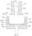
- FIG. 1 is an assembly diagram of a rotary extrusion forming die for a cabin section workpiece according to the present disclosure
- FIG. 2 is a schematic diagram of an irregularly-shaped thin-walled cabin section workpiece according to the present disclosure
- FIG. 3 is a front view of a blank according to the present disclosure.
- FIG. 4 is a top view of the blank according to the present disclosure.
- FIG. 5 is a front view of an ejector plate according to the present disclosure.
- FIG. 6 is a top view of the ejector plate according to the present disclosure.
- FIG. 7 is a front view of a female die according to the present disclosure.
- FIG. 8 is a top view of the female die according to the present disclosure.
- FIG. 9 is a schematic diagram in which a left half male die and a right half male die have not moved down according to the present disclosure.
- FIG. 10 is a schematic diagram in which the left half male die and the right half male die have moved down according to the present disclosure
- FIG. 11 is a schematic diagram in which the left half punch and the right half punch step left and right and the die rotates with the blank according to the present disclosure
- FIG. 12 is a schematic diagram in which the left half male die and the right half male die have moved up and the female die rotates with the blank according to the present disclosure
- FIG. 13 is a schematic diagram in which the left half male die and the right half male die move towards each other in opposite directions according to the present disclosure
- FIG. 14 is a schematic diagram in which the left half male die and the right half male die have moved up and the female die rotates with the blank according to the present disclosure
- FIG. 15 is a schematic diagram in which the female die stops rotating and the left half male die and the right half male die are closed and move up according to the present disclosure.
- FIG. 16 is a schematic diagram of the ejection of a formed workpiece according to the present disclosure.
- the present disclosure provides a rotary extrusion forming die for a cabin section workpiece, which is mainly used for extrusion forming of an irregularly-shaped thin-walled cabin section workpiece.
- the forming die includes a male die, a female die 19 , an upper die assembly 100 and a lower die base 22 .
- the female die 19 is a floating die which can rotate on the lower die base 22 and float up and down.
- a die cavity 193 is provided in the female die 19 , and can be used for receiving a blank 3 , and the female die 19 arranged on the lower die base 22 in such a manner that it can rotate about a vertical axis, i.e., the groove 19 can rotate horizontally on the lower die base 22 .
- the male die is arranged on the upper die assembly 100 and can extend into the die cavity 193 along with the upper die assembly 100 , and the upper die assembly 100 can drive the male die to move in the vertical and horizontal directions to perform extrusion forming on the blank 3 in the die cavity 193 , thus extruding the blank 3 into the cabin section workpiece of an irregularly-shaped thin-walled structure.
- the irregularly-shaped thin-walled structure refers to a thin-walled structure of the cabin section workpiece with a non-straight wall face as its machining face.
- the male die includes a left half male die 13 and a right half male die 14
- the upper die assembly 100 includes an upper die base 11 and a push-pull device, wherein the left half male die 13 and the right half male die 14 are movably arranged on the upper die base 11 along the horizontal direction, and a push-pull device is arranged on the upper die base 11 and connected to the left half male die 13 and the right half male die 14 respectively, so as to drive the left half male die 13 and the right half male die 14 to move left and right in the horizontal direction.
- the upper die base 11 is connected to a press to drive the left half male die 13 and the right half male die 14 to move up and down in the vertical direction, thereby performing extrusion forming on the blank 3 .
- the upper die assembly 100 further includes a press connector 10 and a wedge 12 .
- An inclined surface 121 is formed on both sides of the wedge 12 respectively, and inclined surfaces are formed between the left half male die 13 and the right half male die 14 , wherein an inclined surface 131 is provided on one side of the left half male die 13 while an inclined surface 141 is provided on one side of the right half male die 14 , and the inclined surfaces 121 on the both sides of the wedge 12 are fitted to the inclined surface 131 of the left half male die 13 and the inclined surface 141 of the right half male die 14 .
- the wedge 12 is arranged in a sliding manner on the inclined surfaces between the left half male die 13 and the right half male die 14 .
- the inclined surface on the left side of the wedge 12 matches with the inclined surface 131 of the left half male die 13 and that on the right side of the wedge 12 matches with the inclined surface 141 of the right half male die 14 .
- the top of the wedge 12 is also connected to the press connector which is connected to the press through the upper die base 11 , so as to drive the wedge 12 to move up and down.
- the press is a double-action press, which can drive the upper die base 11 and wedge 12 to move respectively.
- the press connector 10 acts on the upper die base 11 to drive the upper die base 11 to move up and down, thereby driving the left half male die 13 and the right half male die 14 to move up and down.
- the press connector 10 acts on the wedge 12 to drive the wedge 12 to move up and down, so that when the push-pull device drives the left half male die 13 and the right half male die 14 to open and close to a preset width, and the wedge 12 is used to limit the horizontal movement of the left half male die 13 and the right half male die 14 .
- the horizontal radial pressure between the left half male die 13 and the right half male die 14 can be counteracted during the extrusion of the blank 3 , thus improving the machining stability of the workpiece.
- the push-pull device includes a left half male die retainer 15 , a left retainer hydraulic cylinder 17 , a right half male die retainer 16 and a right retainer hydraulic cylinder 18 .
- the left half male die 13 is arranged on the upper die base 11 through a left half male die retainer 15
- the left retainer hydraulic cylinder 17 is arranged on the upper die base 11 to drive the left half male die 13 to move left and right.
- the right half male die 14 is arranged on the upper die base 11 through the right half male die retainer 16
- the right retainer hydraulic cylinder 18 is arranged on the upper die base 11 to drive the right half male die 14 to move left and right.
- one end of the left retainer hydraulic cylinder 17 is fixed on the upper die base 11 while the other end thereof is fixed on the left half male die retainer 15 .
- One end of the right retainer hydraulic cylinder 18 is fixed on the upper die base 11 while the other end thereof is fixed on the right half male die retainer 16 .
- the left half male die retainer 15 and the right half male die retainer 16 slide left and right on the upper die base 11 respectively through the left retainer hydraulic cylinder 17 and the right retainer hydraulic cylinder 18 .
- the left half male die retainer 15 and the right half male die retainer 16 are mounted on the upper die base 11 through guide grooves with a T-shaped section, and can slide left and right on the T-shaped guide grooves, to achieve tight fit.
- the left retainer hydraulic cylinder 17 and the right retainer hydraulic cylinder 18 respectively drive the left half male die 13 and the right half male die 14 to move at the same time, and an elastic buffer, which plays a buffering role, is provided at a coupling end of the right retainer hydraulic cylinder 18 and the upper die base 11 .
- the rotary extrusion forming die for a cabin section workpiece provided by the present disclosure further includes a rotation driving device 20 , which is arranged on the side of the female die 19 to drive the female die 19 to rotate about the vertical axis.
- the rotation driving device 20 includes a first gear 201 , a first pulley 202 , a second gear 203 , a second pulley 204 and a motor 206 .
- a keyway which is inlaid with a flat key and connected to the first gear 201 through the flat key, is provided on the outer side wall 191 of the female die 19 , and the first gear 201 is engaged with the second gear 203 which is in drive connection with the first pulley 202 .
- the first pulley 202 is in drive connection with the second pulley 204 through a belt
- the motor 206 is in drive connection with the second pulley 204 through a clutch 205 to drive the second pulley 204 to rotate.
- the clutch 205 is a dog clutch, and the power of the motor 206 is transmitted to the female die 19 through a coupling, the clutch 205 , the second pulley 204 , the first pulley 202 , the second gear 203 and the first gear 201 .
- the clutch 205 By controlling the clutch 205 , the power transmission between the motor 206 and the female die 19 can be randomly connected and disconnected. According to the actual power required for extruding and rotating functions, the blank of various sizes can be extruded and rotated by replacing the motor 206 and a variable gearing mechanism.
- the rotary extrusion forming die for a cabin section workpiece provided by the present disclosure further includes a floating device.
- a circular cavity 221 is provided on the lower die base 22 , and the floating device is arranged at the bottom of the circular cavity 221 for driving the female die 19 to float up and down.
- the female die 19 is rotatably arranged in the circular cavity 221 and located at an upper end of the floating device, and the floating device is used for driving the female die 19 to float up and down.
- there are a plurality of floating devices which are uniformly distributed at the bottom of the circular cavity 221 , and are respectively used for driving the female die 19 to float up and down and keep balance.
- the floating device includes steel ball bearing brackets 24 , steel balls 25 and springs 26 .
- steel ball bearing bracket 24 is fixedly arranged in the lower die base 22 by screws, and a receiving cavity 241 with the spring 26 inside is arranged in the steel ball bearing bracket 24 .
- the steel ball 25 is arranged in the receiving cavity 241 and located at the top of the spring 26 , and can move up and down as the spring 26 stretches.
- Annular grooves 251 are correspondingly provided at the bottom of the female die 19 , and the steel ball 25 can roll in the annular groove 251 under the acting force of the spring.
- the floating device can drive the female die 19 to float up and down on the lower die base 22 .
- the annular grooves 251 are correspondingly provided at the bottom of the female die 19 , the floating device and the female die 19 are connected more reliably without easily disengaging from each other.
- the rotary extrusion forming die for a cabin section workpiece provided by the present disclosure further includes stopper 21 .
- Stopper 21 is fixedly arranged on an upper end face of the lower die base 22 and located at the side of the circular cavity 221 .
- a groove is provided on an inner side of the stopper 21 along the radial direction of the female die 19 , and an annular stiffener 192 is provided on the outer side wall 191 of the female die 19 .
- the female die 19 extends into the groove through the annular stiffener 192 and can float up and down in the groove, and the stopper 21 plays a role of limiting position in the radial direction of the female die 19 .
- the female die 19 can stably float up and down in the stopper 21 , with its floating height H being limited by the stopper 21 , so the female die 19 is not easy to fall off, and the stopper 21 can act as a guide to improve forming accuracy.
- annular oil galleries 210 are provided in positions where the annular stiffeners 192 is in contact with the groove.
- the annular oil galleries 210 are provided at the contact surfaces between the groove and the annular stiffeners 192 , which can reduce the friction between the groove and the annular stiffeners 192 .
- the annular oil galleries 210 are provided in positions where the side wall of the female die 19 is in contact with the circular cavity 221 , which can also reduce the friction between the side wall of the female die 19 and the circular cavity 221 .
- the rotary extrusion forming die for a cabin section workpiece provided by the present disclosure further includes thrust bearing plates 23 having an upper thrust bearing plate arranged at the bottom of the female die 19 and a lower thrust bearing plate arranged at the bottom of the circular cavity 221 .
- the upper thrust bearing plate and the lower thrust bearing plate are interlocked through a locking structure, thereby limiting the movement of the female die 19 .
- the locking structure can be a bump and groove structure.
- the rotary extrusion forming die for a cabin section workpiece further includes a stripping device which includes an ejector bar 27 and an ejector plate 29 , wherein a through hole 28 is arranged at the center of the die cavity 193 , the ejector plate 29 is arranged at the bottom of the die cavity 193 , the blank 3 is located at an upper end of the ejector plate 29 , and the ejector bar 27 is telescopically arranged in the through hole 28 .
- a stripping device which includes an ejector bar 27 and an ejector plate 29 , wherein a through hole 28 is arranged at the center of the die cavity 193 , the ejector plate 29 is arranged at the bottom of the die cavity 193 , the blank 3 is located at an upper end of the ejector plate 29 , and the ejector bar 27 is telescopically arranged in the through hole 28 .
- one end of the ejector bar 27 passes through the through hole 28 and abuts against the ejector plate 29 , and the other end thereof is connected to a drive member.
- a plurality of notches for interlocking with short stiffeners 195 on the female die are provided circumferentially on the ejector plate 29 , and there may be five, six or seven notches. In some embodiments, there may be five, six or seven short stiffeners 195 on the female die corresponding to the notches.
- the blank 3 in order to facilitate the rotation of the blank 3 along with the female die 19 , is of a hollow structure into which the male die can extend, to extrude the inner side wall 31 of the blank 3 .
- the outer side wall 32 of the blank 3 is fitted in the die cavity 193 , and bulges 33 are provided at the bottom of the blank 3 .
- First notches 291 and second notches 292 are provided on the ejector plate 29 , the short stiffeners 195 matched with the first notches 291 are provided at the bottom of the die cavity 193 , and the blank 3 is clamped in the second notches 292 through the bulges 33 to avoid self-rotation during rotation.
- the rotary extrusion forming die for a cabin section workpiece can avoid machining by cutting, improve material utilization rate, and reduce consumption in subsequent machining stages, thereby reducing the production cost and improving the production efficiency. On the other hand, it can also improve the mechanical performance of the main body of the workpiece and avoid the decline in the load-bearing capacity caused by cutting-off streamline. Furthermore, by employing the solution provided by the present disclosure, the workpiece adopts an isothermal forming mode in the forming process, i.e., the blank is always closed in the female die in the forming process, thereby avoiding the temperature reduction of the blank, eliminating the uneven deformation caused by the heat exchange between the blank and the air, further improving the deformation uniformity and reducing the wall thickness difference.
- the present disclosure also provides a rotary extrusion forming method for a cabin section workpiece, which can be applied to the rotary extrusion forming die for a cabin section workpiece. Further, the method specifically includes a male die, a female die, an upper die assembly 100 , a lower die base and a rotation driving device.
- the male die is arranged on the upper die assembly 100 which can drive the male die to move up and down in the vertical direction and to move left and right in the horizontal direction;
- the female die is arranged on the lower die base in such a manner that it can rotate about a vertical axis; and the rotation driving device is in drive connection with the female die and can drive the female die to rotate about the vertical axis.
- the method further includes the following steps as follows.
- the workpiece can be formed by one-time heating and one-time rotary extrusion of a main body thereof under the condition of mass production, which avoids machining by cutting, improves material utilization rate, and reduces consumption in subsequent machining stages, thereby reducing the production cost, improving the production efficiency and effectively shortening the production process.
- the workpiece machining process is as follows: the rotation driving device 20 is started up to drive the female die 19 to rotate on the lower die base 22 , and the female die 19 drives the blank 3 to rotate, and the left half male die 13 and the right half male die 14 are closed on the upper die base 11 and fixed under the press connector 10 .
- the upper die base 11 drives the left half male die 13 and the right half male die 14 to move down.
- the press connector 10 drives the wedge 12 to move down, and a push-pull device drives the left half male die 13 and the right half male die 14 to feed separately, so as to start to extrude the inner side wall 31 of the blank 3 .
- the wedge 12 remains motionless, and the upper die base 11 drives the left half male die 13 and the right half male die 14 to move up.
- the press connector 10 drives the wedge 12 to move up, and a gap is left between the left half male die 13 and the right half male die 14 , so that the push-pull device pushes the left half male die 13 and the right half male die 14 to move left and right.
- the upper die base 11 drives the left half male die 13 and the right half male die 14 to move up, and the formed workpiece and an ejector plate 29 held in the female die 19 are jacked up by an ejector bar 27 to complete die stripping.
- an inclined surface is formed on both sides of the wedge, respectively, and inclined surfaces, on which the wedge is arranged in a sliding manner, are formed between the left half male die and the right half male die; the inclined surface on the left side of the wedge matches with the inclined surface of the left half male die and the inclined surface on the right side of the wedge matches with the inclined surface of the right half male die.
- the wedge slides up and down on the inclined surfaces between the left half male die and the right half male die to drive the left half male die and the right half male die to open or close.
- the inclined surfaces 121 on the both sides of the wedge 12 are consistent with the gradient of an outer side wall 32 of the blank, and/or are consistent with the gradient of the inclined surfaces of the left half male die 13 and the right half male die 14 .
- the die cavity 193 is provided in the female die 19 , and the inner wall of the die cavity 193 is consistent with the gradient of the outer side walls 32 of the blank.
- a circular cavity 221 having a floating device arranged at the bottom thereof, is provided on the lower die base 22 , and the female die 19 is rotatably arranged in the circular cavity 221 and floats up and down in the circular cavity 221 through the floating device.
- a stopper 21 having a groove arranged on an inner side face thereof, is provided on an upper end face of the lower die base 22 .
- An annular stiffener 192 is provided on the outer side wall 191 of the female die 19 , and the female die 19 is clamped in the groove through the annular stiffener 192 and can float up and down in the groove.
- the female die 19 moves down to a lower limit position of the groove, the upper thrust bearing plate and the lower thrust bearing plate are interlocked through a locking structure, thereby limiting the movement of the female die 19 .
- the locking structure can be a bump and groove structure.
- the blanking can be performed by sawing the ready-made blank, the workpiece can be formed by one-time heating and one-time rotary extrusion of a main body thereof, which avoids machining by cutting, improves material utilization rate, and reduces consumption in subsequent machining stages, thereby reducing the production cost and improving the production efficiency
Landscapes
- Engineering & Computer Science (AREA)
- Mechanical Engineering (AREA)
- Shaping Metal By Deep-Drawing, Or The Like (AREA)
- Extrusion Of Metal (AREA)
Abstract
Description
-
- S1: preparing a hollow truncated cone-shaped blank;
- S2: heating the prepared blank to a molding temperature and holding, and preheating the female die and the male die to above the molding temperature and holding;
- S3: assembling the upper die assembly on a press;
- S4: applying lubricant on the female die and the male die, and placing and fixing the blank into a die cavity of the female die;
- S5: starting up the rotation driving device to drive the female die to rotate on the lower die base, so that the female die drives the blank to rotate; starting up the press to move the male die down to a machining position of the blank in the die cavity through the upper die assembly, and machining inner side walls of the blank; and
- S6: after the blank is formed by machining, making the male die move up by the press to a preset position through the upper die assembly.
-
- S7: jacking an ejector plate at the bottom of the die cavity up by an ejector bar, so as to strip the formed workpiece.
-
- S1: Blanking is performed to prepare a hollow truncated cone-shaped blank. Specifically, the blank is preferably made of light alloy, which is aluminum alloy, titanium alloy or magnesium alloy, and so on.
- S2: Preparation for forming is performed, namely the prepared blank is heated to a molding temperature and held at this temperature, the molding temperature to which the blank is heated is a recrystallization temperature of the blank material, after the blank is heated to the molding temperature (i.e., the recrystallization temperature), the holding time is preferably 4-6 hours, preferably 4 hours, and the female die and the male die are preheated to above the molding temperature and held.
- S3: Die assembly is performed, namely the
upper die assembly 100 is assembled on a press. Further, the die assembly includes an upper die base and a press connector which are in drive connection with the press respectively, and the press is a double-action press. The male die includes a left half male die and a right half male die which are movably arranged on the upper die base along the horizontal direction. A wedge connected to the press connector is arranged between the left half male die and the right half male die, and the upper die base and the press connector are in drive connection with the press respectively. - S4: Lubricant is applied evenly on the
die cavity 193 of thefemale die 19, the left half male die 13 and the right half male die 14, and the heated blank is put and fixed into thedie cavity 193 of thefemale die 19. The lubricant application is mainly used to facilitate die stripping. At the same time, the deformation between the blank and thedie cavity 193 in the process of extruding the blank by the male die can be avoided, and the machining accuracy is improved. - S5: Forming is performed, namely the rotation driving device is started up to drive the female die to rotate on the lower die base, so that the female die drives the blank to rotate; the press is started up to move the male die down to a machining position of the blank in the die cavity through the
upper die assembly 100, and the inner side walls of the blank are machined. - S6: After the blank is formed by machining, the press makes the male die up move to a preset position through the press connector.
- S7: An ejector plate at the bottom of the die cavity is jacked up by an ejector bar, so as to strip the formed workpiece.
- S8: Application of lubricating oil is continued, so as to proceed with the next process of rotary extrusion of a shaped thin-walled cabin section workpiece.
Claims (18)
Applications Claiming Priority (2)
| Application Number | Priority Date | Filing Date | Title |
|---|---|---|---|
| CN201911024770.9 | 2019-10-25 | ||
| CN201911024770.9A CN110743928B (en) | 2019-10-25 | 2019-10-25 | A kind of cabin section workpiece rotary extrusion molding method |
Publications (2)
| Publication Number | Publication Date |
|---|---|
| US20210121928A1 US20210121928A1 (en) | 2021-04-29 |
| US11858023B2 true US11858023B2 (en) | 2024-01-02 |
Family
ID=69280049
Family Applications (1)
| Application Number | Title | Priority Date | Filing Date |
|---|---|---|---|
| US17/077,896 Active 2042-01-08 US11858023B2 (en) | 2019-10-25 | 2020-10-22 | Rotary extrusion forming method for cabin section workpiece |
Country Status (2)
| Country | Link |
|---|---|
| US (1) | US11858023B2 (en) |
| CN (1) | CN110743928B (en) |
Families Citing this family (8)
| Publication number | Priority date | Publication date | Assignee | Title |
|---|---|---|---|---|
| CN112547891A (en) * | 2020-11-19 | 2021-03-26 | 江苏德博金属制品有限公司 | Metal hot extrusion forming device |
| CN113790268B (en) * | 2021-09-01 | 2024-08-30 | 浙江东溟科技有限公司 | Deep water energy storage control cabin |
| CN114769590B (en) * | 2022-05-11 | 2022-11-22 | 淄博元绪冶金机械有限公司 | Female die floating adjusting mechanism of powder metallurgy press for processing top |
| CN115709244B (en) * | 2022-11-09 | 2023-06-09 | 珠海信城智能制造有限公司 | Hierarchical separation type forming die with automatic demolding function |
| CN116329395B (en) * | 2023-04-11 | 2023-09-22 | 清远市拓远汽车零部件有限公司 | Multistage drawing die for combined aluminum alloy plate |
| CN116727521B (en) * | 2023-08-11 | 2023-12-08 | 辽宁华天航空科技股份有限公司 | Thermoforming mold and method for titanium alloy thin-wall part |
| CN116944817A (en) * | 2023-09-20 | 2023-10-27 | 成都先进金属材料产业技术研究院股份有限公司 | Preparation method of titanium alloy multi-wedge belt wheel |
| CN120115602B (en) * | 2025-03-10 | 2025-12-02 | 西安航天发动机有限公司 | A die for denting the surface of a cylindrical metal part |
Citations (8)
| Publication number | Priority date | Publication date | Assignee | Title |
|---|---|---|---|---|
| GB2414206A (en) | 2004-05-18 | 2005-11-23 | Tsubakimoto Chain Co | Cylindrical bearing member and method and apparatus for manufacturing same |
| CN104399771A (en) | 2014-12-02 | 2015-03-11 | 中北大学 | Inner transverse bar extrusion die for cylindrical component |
| CN104624694A (en) * | 2014-12-02 | 2015-05-20 | 中北大学 | Method for extruding inner transverse rib of cylindrical piece |
| CN106607468A (en) * | 2017-01-07 | 2017-05-03 | 中北大学 | Differential-speed extrusion forming method of magnesium alloy high performance cup-shaped piece |
| CN108580622A (en) | 2018-03-19 | 2018-09-28 | 武汉理工大学 | A kind of I types indulge radial extrusion forming process design method in muscle ring mould |
| CN109590348A (en) | 2019-01-08 | 2019-04-09 | 中北大学 | A kind of more inner ring muscle rotary extradition forming dies of cylindrical member |
| CN208758353U (en) | 2018-09-07 | 2019-04-19 | 佛山市三水鸿安联铝合金制品有限公司 | A kind of aluminum profile processing molding machine with cooling system |
| CN109692907A (en) * | 2019-01-08 | 2019-04-30 | 中北大学 | A kind of more inner ring muscle rotary extrusion forming methods of cylindrical member |
-
2019
- 2019-10-25 CN CN201911024770.9A patent/CN110743928B/en active Active
-
2020
- 2020-10-22 US US17/077,896 patent/US11858023B2/en active Active
Patent Citations (8)
| Publication number | Priority date | Publication date | Assignee | Title |
|---|---|---|---|---|
| GB2414206A (en) | 2004-05-18 | 2005-11-23 | Tsubakimoto Chain Co | Cylindrical bearing member and method and apparatus for manufacturing same |
| CN104399771A (en) | 2014-12-02 | 2015-03-11 | 中北大学 | Inner transverse bar extrusion die for cylindrical component |
| CN104624694A (en) * | 2014-12-02 | 2015-05-20 | 中北大学 | Method for extruding inner transverse rib of cylindrical piece |
| CN106607468A (en) * | 2017-01-07 | 2017-05-03 | 中北大学 | Differential-speed extrusion forming method of magnesium alloy high performance cup-shaped piece |
| CN108580622A (en) | 2018-03-19 | 2018-09-28 | 武汉理工大学 | A kind of I types indulge radial extrusion forming process design method in muscle ring mould |
| CN208758353U (en) | 2018-09-07 | 2019-04-19 | 佛山市三水鸿安联铝合金制品有限公司 | A kind of aluminum profile processing molding machine with cooling system |
| CN109590348A (en) | 2019-01-08 | 2019-04-09 | 中北大学 | A kind of more inner ring muscle rotary extradition forming dies of cylindrical member |
| CN109692907A (en) * | 2019-01-08 | 2019-04-30 | 中北大学 | A kind of more inner ring muscle rotary extrusion forming methods of cylindrical member |
Also Published As
| Publication number | Publication date |
|---|---|
| CN110743928A (en) | 2020-02-04 |
| CN110743928B (en) | 2021-07-27 |
| US20210121928A1 (en) | 2021-04-29 |
Similar Documents
| Publication | Publication Date | Title |
|---|---|---|
| US11858023B2 (en) | Rotary extrusion forming method for cabin section workpiece | |
| AU2020102822A4 (en) | Rotation Extrusion Molding Die For Cabin Workpiece | |
| CN104624694B (en) | A kind of interior horizontal bar pressing method of cylindrical member | |
| CN114178555A (en) | Main shaft structure applied to friction additive manufacturing device | |
| CN109530471B (en) | A kind of extrusion forming die for thin-walled near-alpine-shaped light alloy components | |
| CN106216472B (en) | A kind of umbellate form housing member warm-extrusion forming method | |
| US12179255B2 (en) | Roll spinning forming device and method for toothed part | |
| CN114985653B (en) | Multidirectional forging process for stainless steel flange | |
| CN101881304B (en) | Assembly structure, method and fixture of pulley and bearing | |
| CN201572808U (en) | Hydraulic servo vibration extruder | |
| CN221109521U (en) | Circular pipe annular outward convex forming device | |
| CN212384300U (en) | Die and molding equipment for extrusion molding | |
| CN211915376U (en) | Open type double-column press device for feeding assembly | |
| CN110743929B (en) | A kind of magnesium alloy ring extrusion forming method | |
| CN103639675B (en) | The processing method of curve surface of raceway and shaping dies in freewheel clutch | |
| CN115193977B (en) | Hydraulic press for isothermal continuous die-forming of metal sheets and forming method thereof | |
| CN117380823A (en) | A stamping device for reducing deformation in the production of LED switching power supplies | |
| CN222198350U (en) | Cold extrusion forming die for forming special-shaped internal spline shaft by tube blank | |
| CN220239947U (en) | Cold header for composite extrusion bearing roller | |
| CN220007352U (en) | Fixing tool for piston ring machining | |
| CN119387338A (en) | Aluminum piston one-piece molding process | |
| CN222182370U (en) | A heat treatment tool for synchronizer gear sleeve | |
| CN119238272B (en) | A polishing machine | |
| CN221388495U (en) | Anti-offset hardware stamping die | |
| CN113042559B (en) | Thinning, stretching and extruding composite forming method for large-height-diameter-ratio cylinder |
Legal Events
| Date | Code | Title | Description |
|---|---|---|---|
| FEPP | Fee payment procedure |
Free format text: ENTITY STATUS SET TO UNDISCOUNTED (ORIGINAL EVENT CODE: BIG.); ENTITY STATUS OF PATENT OWNER: SMALL ENTITY |
|
| AS | Assignment |
Owner name: NORTH UNIVERSITY OF CHINA, CHINA Free format text: ASSIGNMENT OF ASSIGNORS INTEREST;ASSIGNORS:ZHAO, XI;ZHANG, ZHIMIN;XUE, YONG;AND OTHERS;REEL/FRAME:054146/0808 Effective date: 20201021 |
|
| FEPP | Fee payment procedure |
Free format text: ENTITY STATUS SET TO SMALL (ORIGINAL EVENT CODE: SMAL); ENTITY STATUS OF PATENT OWNER: SMALL ENTITY |
|
| STPP | Information on status: patent application and granting procedure in general |
Free format text: APPLICATION DISPATCHED FROM PREEXAM, NOT YET DOCKETED |
|
| STPP | Information on status: patent application and granting procedure in general |
Free format text: DOCKETED NEW CASE - READY FOR EXAMINATION |
|
| STPP | Information on status: patent application and granting procedure in general |
Free format text: RESPONSE TO NON-FINAL OFFICE ACTION ENTERED AND FORWARDED TO EXAMINER |
|
| STPP | Information on status: patent application and granting procedure in general |
Free format text: NOTICE OF ALLOWANCE MAILED -- APPLICATION RECEIVED IN OFFICE OF PUBLICATIONS |
|
| STPP | Information on status: patent application and granting procedure in general |
Free format text: PUBLICATIONS -- ISSUE FEE PAYMENT RECEIVED |
|
| STPP | Information on status: patent application and granting procedure in general |
Free format text: PUBLICATIONS -- ISSUE FEE PAYMENT VERIFIED |
|
| STCF | Information on status: patent grant |
Free format text: PATENTED CASE |