US11845033B2 - Exhaust gas purification filter - Google Patents
Exhaust gas purification filter Download PDFInfo
- Publication number
- US11845033B2 US11845033B2 US17/592,206 US202217592206A US11845033B2 US 11845033 B2 US11845033 B2 US 11845033B2 US 202217592206 A US202217592206 A US 202217592206A US 11845033 B2 US11845033 B2 US 11845033B2
- Authority
- US
- United States
- Prior art keywords
- porosity
- cells
- partition wall
- exhaust gas
- skin member
- Prior art date
- Legal status (The legal status is an assumption and is not a legal conclusion. Google has not performed a legal analysis and makes no representation as to the accuracy of the status listed.)
- Active, expires
Links
Images


Classifications
-
- B—PERFORMING OPERATIONS; TRANSPORTING
- B01—PHYSICAL OR CHEMICAL PROCESSES OR APPARATUS IN GENERAL
- B01D—SEPARATION
- B01D46/00—Filters or filtering processes specially modified for separating dispersed particles from gases or vapours
- B01D46/24—Particle separators, e.g. dust precipitators, using rigid hollow filter bodies
- B01D46/2403—Particle separators, e.g. dust precipitators, using rigid hollow filter bodies characterised by the physical shape or structure of the filtering element
- B01D46/2418—Honeycomb filters
- B01D46/2451—Honeycomb filters characterized by the geometrical structure, shape, pattern or configuration or parameters related to the geometry of the structure
- B01D46/2486—Honeycomb filters characterized by the geometrical structure, shape, pattern or configuration or parameters related to the geometry of the structure characterised by the shapes or configurations
- B01D46/249—Quadrangular e.g. square or diamond
-
- B—PERFORMING OPERATIONS; TRANSPORTING
- B01—PHYSICAL OR CHEMICAL PROCESSES OR APPARATUS IN GENERAL
- B01D—SEPARATION
- B01D39/00—Filtering material for liquid or gaseous fluids
- B01D39/14—Other self-supporting filtering material ; Other filtering material
- B01D39/20—Other self-supporting filtering material ; Other filtering material of inorganic material, e.g. asbestos paper, metallic filtering material of non-woven wires
- B01D39/2068—Other inorganic materials, e.g. ceramics
- B01D39/2072—Other inorganic materials, e.g. ceramics the material being particulate or granular
- B01D39/2079—Other inorganic materials, e.g. ceramics the material being particulate or granular otherwise bonded, e.g. by resins
-
- B—PERFORMING OPERATIONS; TRANSPORTING
- B01—PHYSICAL OR CHEMICAL PROCESSES OR APPARATUS IN GENERAL
- B01D—SEPARATION
- B01D39/00—Filtering material for liquid or gaseous fluids
- B01D39/14—Other self-supporting filtering material ; Other filtering material
- B01D39/20—Other self-supporting filtering material ; Other filtering material of inorganic material, e.g. asbestos paper, metallic filtering material of non-woven wires
- B01D39/2068—Other inorganic materials, e.g. ceramics
- B01D39/2082—Other inorganic materials, e.g. ceramics the material being filamentary or fibrous
- B01D39/2089—Other inorganic materials, e.g. ceramics the material being filamentary or fibrous otherwise bonded, e.g. by resins
-
- B—PERFORMING OPERATIONS; TRANSPORTING
- B01—PHYSICAL OR CHEMICAL PROCESSES OR APPARATUS IN GENERAL
- B01D—SEPARATION
- B01D46/00—Filters or filtering processes specially modified for separating dispersed particles from gases or vapours
- B01D46/24—Particle separators, e.g. dust precipitators, using rigid hollow filter bodies
- B01D46/2403—Particle separators, e.g. dust precipitators, using rigid hollow filter bodies characterised by the physical shape or structure of the filtering element
- B01D46/2418—Honeycomb filters
- B01D46/2425—Honeycomb filters characterized by parameters related to the physical properties of the honeycomb structure material
- B01D46/2429—Honeycomb filters characterized by parameters related to the physical properties of the honeycomb structure material of the honeycomb walls or cells
-
- B—PERFORMING OPERATIONS; TRANSPORTING
- B01—PHYSICAL OR CHEMICAL PROCESSES OR APPARATUS IN GENERAL
- B01D—SEPARATION
- B01D46/00—Filters or filtering processes specially modified for separating dispersed particles from gases or vapours
- B01D46/24—Particle separators, e.g. dust precipitators, using rigid hollow filter bodies
- B01D46/2403—Particle separators, e.g. dust precipitators, using rigid hollow filter bodies characterised by the physical shape or structure of the filtering element
- B01D46/2418—Honeycomb filters
- B01D46/2425—Honeycomb filters characterized by parameters related to the physical properties of the honeycomb structure material
- B01D46/2444—Honeycomb filters characterized by parameters related to the physical properties of the honeycomb structure material of the outer peripheral sealing
-
- B—PERFORMING OPERATIONS; TRANSPORTING
- B01—PHYSICAL OR CHEMICAL PROCESSES OR APPARATUS IN GENERAL
- B01D—SEPARATION
- B01D46/00—Filters or filtering processes specially modified for separating dispersed particles from gases or vapours
- B01D46/24—Particle separators, e.g. dust precipitators, using rigid hollow filter bodies
- B01D46/2403—Particle separators, e.g. dust precipitators, using rigid hollow filter bodies characterised by the physical shape or structure of the filtering element
- B01D46/2418—Honeycomb filters
- B01D46/2425—Honeycomb filters characterized by parameters related to the physical properties of the honeycomb structure material
- B01D46/24491—Porosity
-
- B—PERFORMING OPERATIONS; TRANSPORTING
- B01—PHYSICAL OR CHEMICAL PROCESSES OR APPARATUS IN GENERAL
- B01D—SEPARATION
- B01D46/00—Filters or filtering processes specially modified for separating dispersed particles from gases or vapours
- B01D46/24—Particle separators, e.g. dust precipitators, using rigid hollow filter bodies
- B01D46/2403—Particle separators, e.g. dust precipitators, using rigid hollow filter bodies characterised by the physical shape or structure of the filtering element
- B01D46/2418—Honeycomb filters
- B01D46/2451—Honeycomb filters characterized by the geometrical structure, shape, pattern or configuration or parameters related to the geometry of the structure
- B01D46/2459—Honeycomb filters characterized by the geometrical structure, shape, pattern or configuration or parameters related to the geometry of the structure of the plugs
-
- B—PERFORMING OPERATIONS; TRANSPORTING
- B01—PHYSICAL OR CHEMICAL PROCESSES OR APPARATUS IN GENERAL
- B01D—SEPARATION
- B01D46/00—Filters or filtering processes specially modified for separating dispersed particles from gases or vapours
- B01D46/24—Particle separators, e.g. dust precipitators, using rigid hollow filter bodies
- B01D46/2403—Particle separators, e.g. dust precipitators, using rigid hollow filter bodies characterised by the physical shape or structure of the filtering element
- B01D46/2418—Honeycomb filters
- B01D46/2451—Honeycomb filters characterized by the geometrical structure, shape, pattern or configuration or parameters related to the geometry of the structure
- B01D46/2462—Honeycomb filters characterized by the geometrical structure, shape, pattern or configuration or parameters related to the geometry of the structure the outer peripheral sealing
-
- B—PERFORMING OPERATIONS; TRANSPORTING
- B01—PHYSICAL OR CHEMICAL PROCESSES OR APPARATUS IN GENERAL
- B01D—SEPARATION
- B01D46/00—Filters or filtering processes specially modified for separating dispersed particles from gases or vapours
- B01D46/24—Particle separators, e.g. dust precipitators, using rigid hollow filter bodies
- B01D46/2403—Particle separators, e.g. dust precipitators, using rigid hollow filter bodies characterised by the physical shape or structure of the filtering element
- B01D46/2418—Honeycomb filters
- B01D46/2451—Honeycomb filters characterized by the geometrical structure, shape, pattern or configuration or parameters related to the geometry of the structure
- B01D46/247—Honeycomb filters characterized by the geometrical structure, shape, pattern or configuration or parameters related to the geometry of the structure of the cells
-
- B—PERFORMING OPERATIONS; TRANSPORTING
- B01—PHYSICAL OR CHEMICAL PROCESSES OR APPARATUS IN GENERAL
- B01D—SEPARATION
- B01D46/00—Filters or filtering processes specially modified for separating dispersed particles from gases or vapours
- B01D46/24—Particle separators, e.g. dust precipitators, using rigid hollow filter bodies
- B01D46/2403—Particle separators, e.g. dust precipitators, using rigid hollow filter bodies characterised by the physical shape or structure of the filtering element
- B01D46/2418—Honeycomb filters
- B01D46/2451—Honeycomb filters characterized by the geometrical structure, shape, pattern or configuration or parameters related to the geometry of the structure
- B01D46/2482—Thickness, height, width, length or diameter
-
- B—PERFORMING OPERATIONS; TRANSPORTING
- B01—PHYSICAL OR CHEMICAL PROCESSES OR APPARATUS IN GENERAL
- B01D—SEPARATION
- B01D46/00—Filters or filtering processes specially modified for separating dispersed particles from gases or vapours
- B01D46/24—Particle separators, e.g. dust precipitators, using rigid hollow filter bodies
- B01D46/2403—Particle separators, e.g. dust precipitators, using rigid hollow filter bodies characterised by the physical shape or structure of the filtering element
- B01D46/2418—Honeycomb filters
- B01D46/2451—Honeycomb filters characterized by the geometrical structure, shape, pattern or configuration or parameters related to the geometry of the structure
- B01D46/2484—Cell density, area or aspect ratio
-
- B—PERFORMING OPERATIONS; TRANSPORTING
- B01—PHYSICAL OR CHEMICAL PROCESSES OR APPARATUS IN GENERAL
- B01D—SEPARATION
- B01D46/00—Filters or filtering processes specially modified for separating dispersed particles from gases or vapours
- B01D46/24—Particle separators, e.g. dust precipitators, using rigid hollow filter bodies
- B01D46/2403—Particle separators, e.g. dust precipitators, using rigid hollow filter bodies characterised by the physical shape or structure of the filtering element
- B01D46/2418—Honeycomb filters
- B01D46/2498—The honeycomb filter being defined by mathematical relationships
-
- F—MECHANICAL ENGINEERING; LIGHTING; HEATING; WEAPONS; BLASTING
- F01—MACHINES OR ENGINES IN GENERAL; ENGINE PLANTS IN GENERAL; STEAM ENGINES
- F01N—GAS-FLOW SILENCERS OR EXHAUST APPARATUS FOR MACHINES OR ENGINES IN GENERAL; GAS-FLOW SILENCERS OR EXHAUST APPARATUS FOR INTERNAL-COMBUSTION ENGINES
- F01N3/00—Exhaust or silencing apparatus having means for purifying, rendering innocuous, or otherwise treating exhaust
- F01N3/02—Exhaust or silencing apparatus having means for purifying, rendering innocuous, or otherwise treating exhaust for cooling, or for removing solid constituents of, exhaust
- F01N3/021—Exhaust or silencing apparatus having means for purifying, rendering innocuous, or otherwise treating exhaust for cooling, or for removing solid constituents of, exhaust by means of filters
- F01N3/022—Exhaust or silencing apparatus having means for purifying, rendering innocuous, or otherwise treating exhaust for cooling, or for removing solid constituents of, exhaust by means of filters characterised by specially adapted filtering structure, e.g. honeycomb, mesh or fibrous
- F01N3/0222—Exhaust or silencing apparatus having means for purifying, rendering innocuous, or otherwise treating exhaust for cooling, or for removing solid constituents of, exhaust by means of filters characterised by specially adapted filtering structure, e.g. honeycomb, mesh or fibrous the structure being monolithic, e.g. honeycombs
-
- F—MECHANICAL ENGINEERING; LIGHTING; HEATING; WEAPONS; BLASTING
- F01—MACHINES OR ENGINES IN GENERAL; ENGINE PLANTS IN GENERAL; STEAM ENGINES
- F01N—GAS-FLOW SILENCERS OR EXHAUST APPARATUS FOR MACHINES OR ENGINES IN GENERAL; GAS-FLOW SILENCERS OR EXHAUST APPARATUS FOR INTERNAL-COMBUSTION ENGINES
- F01N3/00—Exhaust or silencing apparatus having means for purifying, rendering innocuous, or otherwise treating exhaust
- F01N3/08—Exhaust or silencing apparatus having means for purifying, rendering innocuous, or otherwise treating exhaust for rendering innocuous
- F01N3/10—Exhaust or silencing apparatus having means for purifying, rendering innocuous, or otherwise treating exhaust for rendering innocuous by thermal or catalytic conversion of noxious components of exhaust
- F01N3/24—Exhaust or silencing apparatus having means for purifying, rendering innocuous, or otherwise treating exhaust for rendering innocuous by thermal or catalytic conversion of noxious components of exhaust characterised by constructional aspects of converting apparatus
-
- B—PERFORMING OPERATIONS; TRANSPORTING
- B01—PHYSICAL OR CHEMICAL PROCESSES OR APPARATUS IN GENERAL
- B01D—SEPARATION
- B01D2239/00—Aspects relating to filtering material for liquid or gaseous fluids
- B01D2239/12—Special parameters characterising the filtering material
- B01D2239/1208—Porosity
-
- B—PERFORMING OPERATIONS; TRANSPORTING
- B01—PHYSICAL OR CHEMICAL PROCESSES OR APPARATUS IN GENERAL
- B01D—SEPARATION
- B01D2239/00—Aspects relating to filtering material for liquid or gaseous fluids
- B01D2239/12—Special parameters characterising the filtering material
- B01D2239/1216—Pore size
-
- B—PERFORMING OPERATIONS; TRANSPORTING
- B01—PHYSICAL OR CHEMICAL PROCESSES OR APPARATUS IN GENERAL
- B01D—SEPARATION
- B01D2239/00—Aspects relating to filtering material for liquid or gaseous fluids
- B01D2239/12—Special parameters characterising the filtering material
- B01D2239/1258—Permeability
-
- B—PERFORMING OPERATIONS; TRANSPORTING
- B01—PHYSICAL OR CHEMICAL PROCESSES OR APPARATUS IN GENERAL
- B01D—SEPARATION
- B01D2279/00—Filters adapted for separating dispersed particles from gases or vapours specially modified for specific uses
- B01D2279/30—Filters adapted for separating dispersed particles from gases or vapours specially modified for specific uses for treatment of exhaust gases from IC Engines
-
- B—PERFORMING OPERATIONS; TRANSPORTING
- B01—PHYSICAL OR CHEMICAL PROCESSES OR APPARATUS IN GENERAL
- B01D—SEPARATION
- B01D39/00—Filtering material for liquid or gaseous fluids
- B01D39/14—Other self-supporting filtering material ; Other filtering material
- B01D39/20—Other self-supporting filtering material ; Other filtering material of inorganic material, e.g. asbestos paper, metallic filtering material of non-woven wires
- B01D39/2068—Other inorganic materials, e.g. ceramics
-
- F—MECHANICAL ENGINEERING; LIGHTING; HEATING; WEAPONS; BLASTING
- F01—MACHINES OR ENGINES IN GENERAL; ENGINE PLANTS IN GENERAL; STEAM ENGINES
- F01N—GAS-FLOW SILENCERS OR EXHAUST APPARATUS FOR MACHINES OR ENGINES IN GENERAL; GAS-FLOW SILENCERS OR EXHAUST APPARATUS FOR INTERNAL-COMBUSTION ENGINES
- F01N2330/00—Structure of catalyst support or particle filter
- F01N2330/06—Ceramic, e.g. monoliths
-
- F—MECHANICAL ENGINEERING; LIGHTING; HEATING; WEAPONS; BLASTING
- F01—MACHINES OR ENGINES IN GENERAL; ENGINE PLANTS IN GENERAL; STEAM ENGINES
- F01N—GAS-FLOW SILENCERS OR EXHAUST APPARATUS FOR MACHINES OR ENGINES IN GENERAL; GAS-FLOW SILENCERS OR EXHAUST APPARATUS FOR INTERNAL-COMBUSTION ENGINES
- F01N2330/00—Structure of catalyst support or particle filter
- F01N2330/30—Honeycomb supports characterised by their structural details
-
- Y—GENERAL TAGGING OF NEW TECHNOLOGICAL DEVELOPMENTS; GENERAL TAGGING OF CROSS-SECTIONAL TECHNOLOGIES SPANNING OVER SEVERAL SECTIONS OF THE IPC; TECHNICAL SUBJECTS COVERED BY FORMER USPC CROSS-REFERENCE ART COLLECTIONS [XRACs] AND DIGESTS
- Y02—TECHNOLOGIES OR APPLICATIONS FOR MITIGATION OR ADAPTATION AGAINST CLIMATE CHANGE
- Y02T—CLIMATE CHANGE MITIGATION TECHNOLOGIES RELATED TO TRANSPORTATION
- Y02T10/00—Road transport of goods or passengers
- Y02T10/10—Internal combustion engine [ICE] based vehicles
- Y02T10/12—Improving ICE efficiencies
Definitions
- the present disclosure relates to an exhaust gas purification filter.
- Exhaust gas discharged from an internal combustion engine such as a gasoline engine or a diesel engine contains particulate matter referred to as particulates (hereinafter referred to as “PM” as appropriate).
- particulates hereinafter referred to as “PM” as appropriate.
- an exhaust gas purification filter is disposed in an exhaust passage in the internal combustion engine.
- an exhaust gas purification filter as the following.
- the exhaust gas purification filter includes: a cell assembly including: a plurality of cells each disposed to extend in an axial direction of the filter, each of the cells having a quadrangular cross-sectional shape in a plane orthogonal to the axial direction, and a partition wall; a plurality of seal members; and a skin member, the partition wall has a porosity P1 of 50% to 70%, and the skin member has a porosity P2 of 50% to 70%, the porosity P1 of the partition wall and the porosity P2 of the skin member satisfy a relationship P1 ⁇ P2, a porosity difference ⁇ P between the porosity P2 and the porosity P1 is 20% or less, and the partition wall includes a plurality of crossing portions, each of the cells has at least one part of an outer periphery defined by a corresponding one of the crossing portions, the at least one part of the outer periphery is rounded to have a radius of curvature R, each of the cells has a radius r of a hydraulic
- FIG. 1 is a schematic diagram of an exhaust gas purification filter in a first embodiment.
- FIG. 2 is an enlarged cross-sectional view in a filter axial direction of the exhaust gas purification filter in the first embodiment.
- FIG. 3 is an enlarged cross-sectional view of a crossing portion of partition wall in a direction orthogonal to a filter axial direction of the exhaust gas purification filter in the first embodiment.
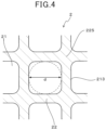
- FIG. 4 is an enlarged cross-sectional view of a cell in the direction orthogonal to the filter axial direction of the exhaust gas purification filter in the first embodiment.
- FIG. 5 is an explanatory diagram illustrating measurement positions for a radius of curvature R and a hydraulic diameter of the cell in the first embodiment.
- FIG. 6 is a schematic diagram of the exhaust gas purification filter disposed in an exhaust passage in the first embodiment.
- FIG. 7 is an enlarged cross-sectional view of an area around a skin member in the direction orthogonal to the filter axial direction of an exhaust gas purification filter in a second embodiment.
- FIG. 8 A is a schematic cross-sectional view of a measurement sample used to measure the material strength of the skin member in a third embodiment
- FIG. 8 B is a schematic cross-sectional view of a measurement sample used to measure the material strength of a cell assembly in the third embodiment.
- FIG. 9 is a schematic diagram illustrating a four-point bending test in the third embodiment.
- FIG. 10 is an explanatory diagram illustrating a relationship between the measurement sample for the material strength and a variable for a section modulus in the third embodiment.
- FIG. 11 is a diagram illustrating a relationship between a porosity difference ⁇ P and thermal stress ⁇ in Experiment Example 1.
- FIG. 12 is a diagram illustrating a relationship between a gas permeability coefficient and a pressure loss in Experiment Example 2.
- FIG. 13 is a diagram illustrating a relationship between the porosity of the partition wall and the gas permeability coefficient in Experiment Example 2.
- FIG. 14 is a diagram illustrating a relationship between the porosity of the partition wall and the material strength of the cell assembly in Experiment Example 2.
- FIG. 15 is a diagram illustrating a relationship between the value of R/r and the pressure loss in Experiment Example 3.
- FIG. 16 is a diagram illustrating a relationship between the value of R/r and an area of a traverse cross section of a cell assembly in Experiment Example 3.
- FIG. 17 is a diagram illustrating a relationship between the value of R/r and the value of 1/R 2 in Experiment Example 3.
- FIG. 18 is a diagram illustrating a relationship between the result of dividing the total area of closed incomplete cells by the area of one complete cell, and an effective cell opening area in Experiment Example 4.
- PTL 1 discloses an exhaust gas purification filter that collects PM discharged from the diesel engine (this exhaust gas purification filter is hereinafter referred to as a “DPF”).
- this exhaust gas purification filter is hereinafter referred to as a “DPF”).
- the PTL 1 describes a DPF that satisfies the relationship Pi ⁇ Po or the relationship Pi>Po and Di ⁇ Do where Pi and Di respectively denote the porosity and pore size of a partition wall in a central portion of a vertical cross section with respect to the axial direction, and Po and Do respectively denote the porosity and pore size of a partition wall in an outer circumferential portion of the vertical cross section with respect to the axial direction.
- such a technique allows cracking to be suppressed during PM regeneration.
- An exhaust gas purification filter that collects PM discharged from the gasoline engine (this exhaust gas purification filter is hereinafter referred to as a “GPF” as appropriate) is exposed to a high temperature environment as compared with a DPF, therefore a flow velocity of exhaust gas is high and the pressure loss tends to increase. Additionally, in the GPF, a central portion of the filter, in which exhaust gas is likely to flow, is likely to have high temperature, and thus thermal stress is caused by a temperature difference between the filter central portion and the filter outer circumferential portion cooled by the exhaust passage such as an exhaust pipe, leading to the likelihood of cracking in the filter outer circumferential portion.
- a technique for increasing filter strength may be to thicken partition wall to increase a filter heat capacity.
- An object of the present disclosure is to provide an exhaust gas purification filter that can improve thermal shock resistance while maintaining a reduced pressure loss.
- An aspect of the present disclosure is an exhaust gas purification filter configured to be disposed in an exhaust passage of a gasoline engine
- the exhaust gas purification filter includes: a cell assembly having an outer surface and including: a plurality of cells each disposed to extend in an axial direction of the filter, each of the cells having a quadrangular cross-sectional shape in a plane orthogonal to the axial direction, and each of the cells having opposing first and second ends in the axial direction, and a partition wall configured to have a porous structure and define the plurality of cells partitioned from each other, a plurality of seal members disposed alternately in the first and second ends of the respective cells, each of the seal members being configured to seal a corresponding one of the first end and the second end of a corresponding one of the cells of the cell assembly; and a skin member configured to have a tubular shape and be mounted on the outer surface of the cell assembly, wherein the partition wall has a porosity P1 of 50% to 70%, and the skin member has a porosity P2
- the above-described exhaust gas purification filter has the above-described configuration.
- the above-described exhaust gas purification filter can improve thermal shock resistance while maintain a reduced pressure loss.
- an exhaust gas purification filter 1 of the present embodiment includes a cell assembly 2 , a seal members 11 , and a skin member 12 .
- the cell assembly 2 and the skin member 12 are formed of ceramics such as cordierite.
- the cell assembly 2 includes a plurality of cells 21 and partition wall 22 having a porous structure.
- Each of the cells 21 extend in a filter axial direction Y.
- the filter axial direction Y normally aligns with an extension direction of the cells 21 .
- the partition wall 22 defines the cells 21 partitioned from each other and the cells 21 form in a grid pattern.
- the partition wall 22 is generally also referred to as cell wall.
- each cell 21 has a quadrangular cross-sectional shape in a plane orthogonal to the filter axial direction Y. Note that in a case where four corners (four vertex portions) of a quadrangular cell shape are rounded, such a cell shape is assumed to be a quadrangle because the cell shape appears like a quadrangle in appearance.
- the skin member 12 has, for example, a tubular shape like a cylindrical shape.
- the skin member 12 is formed integrally on an outer surface of the cell assembly 2 .
- the axial direction of the skin member 12 normally aligns with the filter axial direction Y.
- the partition wall 22 partition the inside of the skin member 12 into a grid form to form a large number of cells 21 .
- the exhaust gas purification filter 1 is a porous body, and the partition wall 22 and the skin member 12 are provided with a large number of pores.
- the exhaust gas purification filter 1 can collect PM contained in exhaust gas by accumulating the PM on surfaces of the partition wall 22 and in the pores.
- the PM is microparticles referred to as particulate matter, particulates, and the like.
- the exhaust gas purification filter 1 is, for example, a columnar body shaped like a cylinder, and has a size that can be changed as appropriate.
- a length L in the filter axial direction Y can be adjusted between 50 mm and 200 mm, and a diameter ⁇ can be adjusted between 100 mm and 165 mm.
- the exhaust gas purification filter 1 includes an inflow end surface 18 and an outflow end surface 19 respectively provided at ends in the filter axial direction Y.
- the inflow end surface 18 is an end surface on the side where an exhaust gas flows in
- the outflow end surface 19 is an end surface on the side where an exhaust gas flows out.
- the inflow end surface 18 and the outflow end surface 19 mean mutually relative surfaces.
- the inflow end surface 18 can also be referred to as a first end surface in the filter axial direction Y
- the outflow end surface 19 can also be referred to as a second end surface in the filter axial direction Y.
- the cell 21 can include first cells 21 a and second cells 21 b . As illustrated in FIG. 2 , each of the first cells 21 a is, for example, open in the inflow end surface 18 and is closed by a corresponding seal member 11 in the outflow end surface 19 . Each of the second cells 21 b is, for example, open in the outflow end surface 19 and is closed by a corresponding seal member 11 in the inflow end surface 18 .
- the seal members 11 are disposed alternately in the ends 211 , 212 of the respective cells in the filter axial direction Y, each of the seal members being configured to seal a corresponding one of the ends 211 , 212 of a corresponding one of the cells of the cell assembly.
- the seal members 11 close the ends 211 of the cells 21 at the inflow end face 18 and close the ends 212 of the cells 21 at the outflow end face 19 .
- the seal members 11 can be formed of ceramics such as cordierite but may be formed of any other material.
- the seal members 11 shaped like plugs are formed.
- the shape of the seal members 11 is not particularly limited, as long as the seal members 11 can seal the ends of the cells 21 .
- the seal members 11 can also be formed by, for example, partly deforming the partition wall 22 in the inflow end surface 18 or the outflow end surface 19 .
- parts of the partition wall 22 form the seal members 11 , and thus the partition wall 22 and the seal members 11 are integrally and continuously formed.
- the first cells 21 a and the second cells 21 b are formed to be alternately arranged adjacent to one another in a lateral direction X orthogonal to the filter axial direction Y and in a vertical direction Z orthogonal to both the filter axial direction Y and the lateral direction X, for example.
- the first cells 21 a and the second cells 21 b are arranged, for example, in a check pattern.
- the partition wall 22 separate the first cells 21 a from the second cells 21 b.
- the porosity P1 of the partition wall 22 and the porosity P2 of the skin member 12 are both 50% or more and 70% or less. Additionally, the porosity P1 of the partition wall 22 and the porosity P2 of the skin member 12 satisfy the relationship P1 ⁇ P2. In addition, a porosity difference ⁇ P defined by P2 ⁇ P1 is 20% or less. The porosity P1 of the partition wall 22 and the porosity P2 of the skin member 12 are measured based on the principle of a mercury intrusion method. Note that the porosity P1 of the partition wall 22 has the same meaning as that of the porosity of the cell assembly 2 .
- the porosity P1 of the partition wall 22 and the porosity P2 of the skin member 12 can be measured by a mercury porosimeter using the principle of the mercury intrusion method.
- a mercury porosimeter for example, AutoPore IV9500 manufactured by Shimadzu Corporation can be used. Measurement conditions are as follows.
- a measurement sample of the cell assembly 2 is a general cube having a length of 1 cm in the filter axial direction Y, a length of 1 cm in the thickness direction of the partition wall 22 , and a length of 1 cm in a direction orthogonal to the filter axial direction Y and the thickness direction of the partition wall 22 described above.
- a measurement sample of the skin member 12 is a general rectangular parallelepiped having a length of 1 cm in the length in the filter axial direction Y, a length equal to the thickness of the skin member 12 , in a filter radial direction from an outer front surface of the skin member 12 toward a central portion of the filter, and a length of 1 cm in a circumferential direction of the skin member 12 .
- Each of the measurement samples is housed in a measurement cell of the mercury porosimeter, and the measurement cell is internally depressurized. Subsequently, mercury is introduced into the measurement cell, which is then pressurized. The pore diameter is measured based on the pressure during the pressurization and the volume of mercury introduced into the pores in the measurement sample.
- the pressure for the measurement ranges from 0.5 psia to 20000 psia. Note that 0.5 psia corresponds to 0.35 ⁇ 10 ⁇ 3 kg/mm 2 and that 2000 psia corresponds to 14 kg/mm 2 .
- the pore diameter corresponding to the pressure ranges from 0.01 ⁇ m to 420 ⁇ m. As constants used to calculate the pore diameter from the pressure, a contact angle of 140° and a surface tension of 480 dyn/cm are used.
- the porosity P1 of the partition wall 22 and the porosity P2 of the skin member 12 are calculated in accordance with relation expressions below.
- Porosity P 1(%) of partition wall 22 total pore volume/(total pore volume+1/true specific gravity of partition wall material) ⁇ 100
- Porosity P 2(%) of skin member 12 total pore volume/(total pore volume+1/true specific gravity of skin member material) ⁇ 100
- the true specific gravity of cordierite can be 2.52.
- the partition wall 22 includes a plurality of crossing portions 225 , each of the cells 21 has at least one part of the outer periphery 213 defined by a corresponding one of the crossing portions, the at least one part of the outer periphery 213 of each of the cells is rounded.
- the outer periphery 213 of the cell 21 in a cross section in a plane orthogonal to the filter axial direction Y, has an arc shape like a circular arc at the crossing portions 225 of the partition wall 22 .
- the crossing portions 225 of the partition wall 22 may correspond to a corner of the cell 21 .
- the outer periphery 213 of the cell 21 being rounded at the crossing portions 225 of the partition wall 22 being substantially the same as the corners of the cell 21 being shaped like an arc.
- the crossing portions 225 are at the position where the partition wall 22 formed into a grid intersect.
- a direction orthogonal to the filter axial direction Y is the filter radial direction in a case where the exhaust gas purification filter 1 is cylindrical.
- the radius of curvature R is assumed to be the radius of the circle of maximum size adjacent to the rounded part of the outer periphery 213 of the cell 21 at the crossing portions 225 of the partition wall 22 .
- the exhaust gas flows inside a circle with a diameter referred to as a hydraulic diameter d.
- the radius of curvature R at the crossing portions 225 of the partition wall 22 and the radius r of the hydraulic diameter d of the cell 21 are measured as follows.
- measurement positions for the radius of curvature R at the crossing portions 225 of the partition wall 22 include a central portion O in the direction orthogonal to the filter axial direction Y and four points each located at 45 degrees from the central portion O and at a distance half the distance between the central portion O and the skin member 12 , from the central portion O.
- the measurement positions for the radius of curvature R include a total of five points circled in FIG. 5 .
- four radii of curvature formed at one crossing portion 225 are measured.
- the radius of curvature is measured at a total of 20 points, and the average of measurement values is determined to be the radius of curvature R at the crossing portion 225 of the partition wall 22 .
- the hydraulic diameter generally refers to the inner diameter of a pipe through which a liquid flows.
- the cross-sectional length L is the sum of sides of the quadrangle and that the length of each side is measured with rounded vertexes in the cross-sectional shape of each cell 21 assumed as right-angled vertexes that are not rounded.
- the measurement positions conform to the measurement positions for the radius of curvature R as described above.
- the hydraulic diameter is measured at the five points corresponding to the measurement positions, and the average of measurement values is determined to be the hydraulic diameter d of each cell 21 .
- R [mm]/r [mm] corresponding to the ratio between the radius of curvature R at each crossing portion 225 of the partition wall 22 and the radius r of the hydraulic diameter d of each cell 21 , is larger than 0.2 and less than 1.
- the exhaust gas purification filter 1 satisfies the relationship 0.2 ⁇ R [mm]/r [mm] ⁇ 1.
- the porosity P1 of the partition wall 22 the porosity P2 of the skin member 12 , the porosity difference ⁇ P, and the R [mm]/r [mm] defined as described above are assumed to be in the particular ranges described above. This allows the exhaust gas purification filter 1 to improve thermal shock resistance while maintaining a reduced pressure loss. The reason why such effects are produced will be explained below.
- the exhaust gas purification filter 1 (GPF) collecting PM discharged from the gasoline engine is exposed to a high temperature environment as compared with a DPF, therefore a flow velocity of exhaust gas is high and the pressure loss tends to increase.
- the porosity P1 of the partition wall 22 needs to be increased.
- the partition wall 22 has a high porosity, that is, porosity P1 of the partition wall 22 is 50% or more, and thus a decrease in gas permeability coefficient of the partition wall 22 is suppressed, allowing a reduced pressure loss to be maintained.
- the porosity P1 of the partition wall 22 and the porosity P2 of the skin member 12 are both 70% or less, and thus a filter strength required at the time of canning can be ensured.
- the relationship P1 ⁇ P2 is satisfied, and the porosity difference ⁇ P, defined by P2 ⁇ P1, is 20% or less.
- the Young's modulus E1 of the cell assembly 2 and the Young's modulus E2 of the skin member 12 satisfy the relationship E1>E2.
- the skin member 12 acts like a cushion to absorb stress occurring when thermal expansion from the central portion of the filter, which has high temperature during use, to the skin member 12 .
- a small Young's modulus produces the effect of allowing the skin member 12 , located at the outermost circumference, to take thermal shock.
- the exhaust gas purification filter 1 alleviates thermal stress to improve thermal shock resistance. Furthermore, in the exhaust gas purification filter 1 , compared to the right-angled shape of the crossing portions 225 , the arc shape of the crossing portions 225 enables an increase in cross-sectional area of the partition wall 22 at the crossing portions 225 . Thus, the partition wall 22 are reinforced at the crossing portions 225 , increasing the filter strength. This particularly increases the strength against the stress in the direction orthogonal to the filter axial direction Y. In this case, in the exhaust gas purification filter 1 , the R [mm]/r [mm] being smaller than 1 leads to the partition wall 22 at the crossing portions 225 being thickened outside the circle with the hydraulic diameter d.
- each cell 21 is rounded at the crossing portions 225 of the partition wall 22 (the corners of the cell 21 are shaped like arcs), the flow of exhaust gas is prevented from being restricted, allowing a possible increase in pressure loss to be suppressed. Furthermore, thickening the partition wall 22 at the crossing portions 225 enables an increase in heat capacity ( ⁇ weight).
- the R [mm]/r [mm] being smaller than 1 increases the heat capacity while minimizing the adverse effect on the pressure loss, correspondingly allowing the thermal heat resistance to be improved.
- the R [mm]/r [mm] being larger than 0.2 allowing a possible significant increase in thermal stress to be suppressed.
- the exhaust gas purification filter 1 allows the thermal shock resistance to be improved while maintaining a reduced pressure loss due to the high porosity.
- the gas permeability coefficient of the partition wall 22 is reduced to increase the pressure loss, leading to difficulty in maintaining a reduced pressure loss.
- the porosity P1 of the partition wall 22 can be preferably 55% or more, more preferably 57% or more, and much more preferably 60% or more.
- the porosity P1 of the partition wall 22 exceeding 70% reduces the filter strength and prevents maintenance of the filter strength required during canning.
- the porosity P1 of the partition wall 22 can be preferably 68% or less, more preferably 67% or less, even more preferably 66% or less, and still much more preferably 65% or less. Additionally, the porosity P2 of the skin member 12 being less than 50% leads to difficulty in allowing the skin member 12 to absorb thermal expansion of the partition wall 22 , located inside the skin member 12 , hindering improvement of thermal shock resistance based on alleviation of stress.
- the porosity P2 of the skin member 12 can be preferably 55% or more, more preferably 57% or more, and much more preferably 60% or more.
- the porosity P2 of the skin member 12 exceeding 70% reduces the filter strength and prevents maintenance of the filter strength required during canning.
- the porosity P2 of the skin member 12 can be preferably 68% or less, more preferably 67% or less, even more preferably 66% or less, and still much more preferably 65% or less.
- a porosity difference ⁇ P exceeding 20% leads to difficulty in setting the porosity P1 of the partition wall 22 and the porosity P2 of the skin member 12 within the particular ranges described above, reducing selection ranges of both porosities. Additionally, the porosity difference ⁇ P exceeding 20% leads to difficulty in manufacturing based on integral molding of the cell assembly 2 and the skin member 12 , increasing a need to add a separate step. This degrades filter manufacturability.
- the porosity difference ⁇ P being 0 provides both the partition wall 22 and the skin member 12 with uniform material properties.
- the filter cell central portion which is likely to have high temperature due to a flow of exhaust gas, is thermally expanded, and when stress reaches the skin member 12 , which has uniform porosity (uniform Young's modulus) with the partition wall 22 , the distortion fails to be resisted, leading to cracking in the skin member 12 .
- the porosity difference ⁇ P can be preferably 1% or more, more preferably 3% or more, and much more preferably 5% or more.
- the difference ⁇ P can be preferably 15% or less, more preferably 12% or less, and much more preferably 10% or more.
- the partition wall 22 at the crossing portions 225 are reinforced by being thickened to reach the inside of the circle with the hydraulic diameter d. This increases the pressure loss to prevent a reduced pressure loss from being maintained.
- the R [mm]/r [mm] being less than 0.2 reduces an area of a traverse cross section of a cell assembly in a plane orthogonal to the filter axial direction Y, reducing the heat capacity of the exhaust gas purification filter 1 .
- the thermal stress is likely to increase significantly, preventing the thermal shock resistance from being improved.
- the R [mm]/r [mm] can be preferably 0.9 or less, more preferably 0.8 or less, and much more preferably 0.7 or less. Additionally, in view of reliable improvement of the thermal heat resistance and the like, the R [mm]/r [mm] can be preferably 0.25 or more, more preferably 0.3 or more, and much more preferably 0.35 or more.
- the skin member 12 can generally have a larger thickness than the partition wall 22 .
- the skin member 12 is, for example, at least twice and at most four times as thick as the partition wall 22 .
- the partition wall 22 can have a thickness of 150 ⁇ m or more and 240 ⁇ m or less.
- the thickness of the partition wall 22 is measured as follows. A took maker's microscope is used to measure the thickness of the partition wall 22 at five points in the filter end surface, and the average of measurement values is determined to be the thickness of the partition wall 22 . Note that the measurement positions at the five points described above are the same as the measurement positions for the radius of curvature R described above.
- the skin member 12 can have a thickness of 0.3 mm or more and 1.0 mm or less.
- the thickness of the skin member 12 is measured as follows. The took maker's microscope is used to measure the thickness of the skin member 12 at eight points in the filter end surface, and the average of measurement values is determined to be the thickness of the skin member 12 .
- the measurement positions at the eight points described above include four intersecting points of the skin member 12 with lines drawn along a grid direction from the central portion O in the direction orthogonal to the filter axial direction Y toward the skin member 12 and four intersecting points of the skin member 12 with lines drawn along a direction inclined at 45° to the grid direction, from the central portion O toward the skin member 12 .
- the exhaust gas purification filter 1 is disposed in an exhaust passage A of a gasoline engine E for use as illustrated in FIG. 6 .
- the exhaust passage A is coupled to a filter case C housing the exhaust gas purification filter 1 inside.
- the exhaust gas purification filter 1 is housed in the filter case C for use with a ceramic mat M wound around the outer circumference of the skin member 12 .
- the exhaust gas purification filter 1 in the filter case C is subjected to an external pressure acting inward in the direction orthogonal to the filter axial direction Y.
- the exhaust gas purification filter 1 can be manufactured, for example, as follows. First, a clay containing a cordierite forming raw material is produced.
- the clay is produced by adjusting silica, talc, aluminum hydroxide, and the like to prepare a cordierite composition, and adding and mixing a binder such as methyl cellulose, a pore making material such as graphite, a lubricating oil, water, and the like, to and with the composition.
- alumina or kaolin may be compounded.
- silica porous silica can be used.
- silica and talc may serve as pore forming raw materials.
- the pore forming raw material is a material for forming pores.
- the pore forming raw material generates a liquid phase component during firing, thus forming pores.
- aluminum hydroxide, alumina, and kaolin may serve as aggregate materials.
- the aggregate material is a material forming ceramic portions other than the pores.
- a honeycomb structure is formed that includes the skin member 12 and the cell assembly 2 that are integrally formed.
- the honeycomb structure includes the skin member 12 , the partition wall 22 , and the cells 21 .
- the seal members 11 are formed after or before firing of the honeycomb structure. Specifically, for example, slurry for forming of the seal members 11 is used to alternately seal the end surfaces of the cells 21 in the honeycomb compact after or before firing, and then by firing to thereby form the seal members 11 .
- the porosity P1 of the partition wall 22 and the porosity P2 of the skin member 12 can be adjusted, for example, based on the presence of the pore making material, compounding of the pore forming raw material, a particle size, and the like.
- FIG. 7 An exhaust gas purification filter according to a second embodiment will be described using FIG. 7 .
- the same reference numerals as those used in the preceding embodiments represent the same components and the like as those in the preceding embodiments unless otherwise noted.
- the cell assembly 2 includes a plurality of incomplete cells 212 a located at the outermost circumference of the cell assembly 2 .
- the cells 21 having a quadrangular cross-sectional shape in a plane orthogonal to the filter axial direction Y are assumed to be complete cells 211 a .
- incomplete cells 212 a are cells that are in contact with the skin member 12 and that have a cross-sectional shape different from a quadrangle in a plane orthogonal to the filter axial direction Y.
- the incomplete cell 212 a is defined by the skin member 12 as well as by the partition wall 22 and thus does not have a complete quadrangular cross-sectional shape.
- incomplete cells 212 a having a cell opening area that is 30% or less of the cell opening area of the complete cell 211 a are closed by closure members 210 .
- the cell opening area of the complete cell 211 a used as a reference, is the average value of measurement values obtained by measuring the cell opening area of the complete cell 211 a at five points in the filter end surface. Note that the measurement positions at the five points described above are the same as the measurement positions for the radius of curvature R described above.
- the incomplete cells 212 a each having a cell opening area that is 30% or less of the cell opening area of each of the complete cells 211 a are small cells through which only a small amount of exhaust gas flows and which do not contribute to increasing the pressure loss. Consequently, by selectively closing such incomplete cells 212 a , included in the plurality of incomplete cells 212 a located at the outermost circumference of the cell assembly 2 , the volume (weight) of the solid portion of the exhaust gas purification filter 1 is increased to enable a local increase in heat capacity without increasing the pressure loss. This enables the thermal heat resistance to be improved.
- the incomplete cells 212 a that are to be closed and that extend in the filter axial direction Y are internally entirely closed by the closure members 210 .
- the incomplete cells 212 a that are to be closed and that extend in the filter axial direction Y are internally entirely filled with the closure members 210 .
- This configuration increases the volume of the solid portion of the exhaust gas purification filter 1 to enable an efficient increase in heat capacity, thus allowing the thermal heat resistance to be more easily improved.
- the incomplete cell 212 a that is to be closed and that extends in the filter axial direction Y may be partially closed by the closure members 210 .
- the closure members 210 can be easily formed by mold design during extrusion. Otherwise, the closure members 210 can also be formed in the same manner as the seal members 11 described above. The other components and effects are the same as those of the first embodiment.
- FIGS. 8 to 10 An exhaust gas purification filter 1 according to a third embodiment will be described using FIGS. 8 to 10 .
- the material strength S A of the cell assembly 2 and the material strength S B of the skin member 12 satisfy the relationship S B ⁇ S A .
- This configuration increases the filter strength.
- the cell assembly 2 has a higher temperature and is more significantly thermally expanded, within the filter base material.
- the increased material strength allows the thermal expansion to be resisted, hindering the thermal stress from reaching the skin member 12 .
- possible cracking in the skin member 12 is more easily suppressed.
- the material strength S A of the cell assembly 2 and the material strength S B of the skin member 12 are measured as follows. First, measurement samples S1 and S2 are collected from the exhaust gas purification filter 1 as illustrated in FIGS. 8 A and 8 B . Specifically, five measurement samples S2 are collected from the exhaust gas purification filter 1 within a range of 30 mm away in the radial direction from the central portion O in the direction orthogonal to the filter axial direction Y (specifically, the filter radial direction), and five measurement samples S1 are collected from the exhaust gas purification filter 1 within a range of 30 mm away in the radial direction from the outermost circumference in the direction orthogonal to the filter axial direction Y. As illustrated in FIG.
- the measurement sample S 1 including the skin member 12 is collected from within the range of 30 mm away from the outermost circumference in the radial direction.
- the measurement samples S1 and S2 each include the cells 21 corresponding to four cells in the width direction and two cells in the thickness direction.
- the measurement samples S1 and S2 each have a length of 50 mm in the filter axial direction Y and are block bodies. Note that in FIG. 8 A and FIG. 8 B , rounding of the outer periphery 213 of each cell 21 at the crossing portions 225 of the partition wall 22 is omitted for convenience.
- the material strength S A of the cell assembly 2 is the average value of the material strengths of the five measurement samples S2.
- the material strength S B of the skin member 12 is the average value of the material strengths of the five measurement samples S1. Note that in the four-point bending test for the measurement samples S1, the skin member 12 side is located on the lower side to apply, to the skin member 12 , tensile stress attributed to bending.
- Bending moment (N*mm) load (N) ⁇ inter-fulcrum distance in four-point bending test (mm)/4
- Equation V The section modulus is expressed by Equation V below. As illustrated in FIG. 10 , in Equation V, the following are assumed: a: the cross-sectional area (mm 2 ) of the measurement sample in a plane orthogonal to the filter axial direction Y, y: the distance (mm) from each reference axis to a member surface, b: the width (mm) of the measurement sample, h: the height (mm) of the measurement sample, and i: the second moment of area of each cell portion (mm 4 ). Although FIG. 10 illustrates the measurement sample S2, the above description also applies to the measurement sample S1.
- Section ⁇ ⁇ modulus ⁇ ⁇ ( mm 3 ) ⁇ Second ⁇ ⁇ moment ⁇ ⁇ of ⁇ ⁇ area ⁇ ⁇ ( mm 4 )
- a plurality of exhaust gas purification filters having a porosity difference ⁇ P varying with the level of P1 within a range from 5% to 20% were produced by setting the porosity P1 of the partition wall to 50%, 55%, 60%, and 65% and varying the porosity P2 of the skin member.
- the R [mm]/r [mm](hereinafter simply referred to as R/r) was set to a constant value larger than 0.2 and smaller than 1.
- a length L in the filter axial direction Y is 100 mm
- a diameter ⁇ is 118 mm
- the partition wall has a thickness of 0.2 mm
- the skin member has a thickness of 0.6 mm
- a cell pitch is 1.47 mm.
- the thermal stress ⁇ can be calculated by the equation E (Young's modulus) ⁇ (thermal expansion coefficient) ⁇ T (temperature difference).
- ⁇ T (temperature difference) can be calculated by the equation ⁇ Q (amount of heat)/ ⁇ M (weight) ⁇ Cp (specific heat) ⁇ .
- the thermal stress ⁇ was determined by CAE-analyzing the relationship between the porosity difference ⁇ P between the partition wall and the skin member, and the thermal stress.
- Ansys classicV.17.2 was used as analysis software.
- FIG. 11 illustrates the relationship between the porosity difference ⁇ P (horizontal axis) and the thermal stress ⁇ (vertical axis).
- a plurality of exhaust gas purification filters were produced such that the porosity P1 of the partition wall varied among the exhaust gas purification filters.
- the porosity difference ⁇ P was set to 5%
- the R/r was set to a constant value larger than 0.2 and smaller than 1.
- the length L in the filter axial direction Y is 100 mm
- the diameter ⁇ is 118 mm
- the partition wall has a thickness of 0.2 mm
- the skin member has a thickness of 0.6 mm
- the cell pitch is 1.47 mm.
- the gas permeability coefficient and the pressure loss were measured.
- FIG. 12 illustrates the relationship between the gas permeability coefficient (horizontal axis) and the pressure loss (vertical axis).
- FIG. 13 illustrates the relationship between the porosity of the partition wall (horizontal axis) and the gas permeability coefficient (vertical axis). Additionally, for each of the exhaust gas purification filters, the material strength of the cell assembly was measured.
- FIG. 14 illustrates the relationship between the porosity of the partition wall (horizontal axis) and the material strength of the cell assembly (vertical axis).
- the pressure loss depends on the gas permeability coefficient, and a reduced pressure loss can be maintained when the gas permeability coefficient is 0.5 or more.
- the gas permeability coefficient is in a proportional relationship with the porosity of the partition wall.
- the gas permeability coefficient is 0.5 when the partition wall has a porosity of 50%, and it is appreciated that the lower limit for the porosity of the partition wall is to be 50% in order to maintain a reduced pressure loss.
- the material strength of the cell assembly decreases with increasing porosity of the partition wall.
- the pressure applied when the exhaust gas purification filter is housed in the filter case is up to 1 MPa.
- the partition wall having a porosity of more than 70% leads to difficulty in achieving the filter strength required during canning.
- the partition wall has a porosity of 70% or less. Note that the above-described reason also applies to the skin member.
- a plurality of exhaust gas purification filters having different R/r values were produced.
- the porosity of the partition wall and the porosity of the skin member both had a constant value of 50% or more and 70% or less, and the porosity difference ⁇ P was set to a constant value of more than 0% and 20% or less.
- the length L in the filter axial direction Y is 100 mm
- the diameter ⁇ is 118 mm
- the partition wall has a thickness of 0.2 mm
- the skin member has a thickness of 0.6 mm
- the cell pitch is 1.47 mm.
- the pressure loss was measured. The pressure loss was measured as follows.
- the exhaust gas purification filter was mounted in an exhaust pipe of a 2.0-L gasoline direct-injection engine and set to a state (steady state) in which the amount of air sucked (Ga) was 100 g/s. Then, exhaust gas containing PM was caused to flow through the exhaust gas purification filter 1 . At this time, the pressure was measured at positions preceding and succeeding the exhaust gas purification filter 1 , and the difference between measurement values was determined to be a pressure loss.
- FIG. 15 illustrates a relationship between the value of R/r (horizontal axis) and the pressure loss (vertical axis).
- FIG. 16 illustrates a relationship between the value of R/r (horizontal axis) and the area of the traverse cross section of the cell assembly (vertical axis).
- FIG. 17 illustrates a relationship between the value of R/r (horizontal axis) and the value of 1/R 2 (vertical axis).
- a value of R/r of 1 or more rapidly increases the pressure loss, whereas a value of R/r of less than 1 allows a reduced pressure loss to be maintained.
- the exhaust gas flows within a circle referred to as a hydraulic diameter such that the circle serves as a boundary, and thus in an area outside the hydraulic diameter, the flow of the exhaust gas is not restricted even in a case where the thickness is increased at the crossing portions of the partition wall to round the outer periphery of the cell.
- This result indicates that the value of R/r needs to be less than 1 in order to maintain a reduced pressure loss.
- the area of the traverse cross section of the cell assembly and the heat capacity decrease as the value of R/r decreases below 1.
- the area of the traverse cross section of the cell assembly is proportional to (R/r) 2 , and thus the heat capacity is proportional to (R/r) 2 .
- the value of R/r is set larger than 0.2 in order to suppress a possible significant increase in thermal stress to improve thermal heat resistance.
- an exhaust gas purification filter was produced in which the porosity P1 of the partition wall and the porosity P2 of the skin member were both 50% or more and 70% or less, and satisfied the relationship P1 ⁇ P2, the porosity difference ⁇ P was 20% or less, and the relationship 0.2 ⁇ R/r ⁇ 1 was satisfied.
- the length L in the filter axial direction Y is 101.6 mm
- the diameter ⁇ is 118.4 mm
- the partition wall has a thickness of 0.216 mm
- the skin member has a thickness of 0.6 mm
- the cell pitch is 1.47 mm
- the cell corner has a radius of curvature R of 0.2 mm.
- the heat capacity of the exhaust gas purification filter portion is increased.
- FIG. 18 illustrates a relationship between the result of dividing the total cell opening area of closed incomplete cells by the cell opening area of one complete cell, and the effective cell opening area.
- the horizontal axis in FIG. 18 indicates how many complete cells have a total cell opening area corresponding to the cell opening area of incomplete cells closed in order of increasing cell opening area.
- the maximum cell opening area of the incomplete cells is 0.4549 mm 2 .
- the result indicates that by using the closure members to close those of the plurality of incomplete cells which have a cell opening area that is 30% or less of the cell opening area of the complete cells, the volume (weight) of the solid portion is increased to enable a local increase in heat capacity, allowing the thermal heat resistance to be further improved.
- the present disclosure is not limited to the above-described embodiments or experiment examples, and various changes may be made to the embodiments and experiment examples without departing from the spirits of the present disclosure. Additionally, the configurations illustrated in the embodiments and experiment examples can be optionally combined together. In other words, the present disclosure has been described in compliance with the embodiments, but it is appreciated that the present disclosure is not limited to the embodiments, structures, or the like. The present disclosure includes various modified examples and variations within the range of equivalency. In addition, the category or conceptual range of the present disclosure includes various combinations or forms and other combinations or forms including only one of the elements or more than one of the elements or less than one of the elements.
Landscapes
- Chemical & Material Sciences (AREA)
- Geometry (AREA)
- Physics & Mathematics (AREA)
- Engineering & Computer Science (AREA)
- Chemical Kinetics & Catalysis (AREA)
- General Engineering & Computer Science (AREA)
- Mechanical Engineering (AREA)
- Combustion & Propulsion (AREA)
- Life Sciences & Earth Sciences (AREA)
- Geology (AREA)
- Inorganic Chemistry (AREA)
- Ceramic Engineering (AREA)
- Health & Medical Sciences (AREA)
- Toxicology (AREA)
- Filtering Materials (AREA)
- Processes For Solid Components From Exhaust (AREA)
- Catalysts (AREA)
- Filtering Of Dispersed Particles In Gases (AREA)
Abstract
Description
- [PTL 1] JP 2004-270569 A
Porosity P1(%) of
Porosity P2(%) of
Material strength (MPa)=bending moment (N*mm)/section modulus (mm3)
Bending moment (N*mm)=load (N)×inter-fulcrum distance in four-point bending test (mm)/4
Claims (6)
Applications Claiming Priority (3)
| Application Number | Priority Date | Filing Date | Title |
|---|---|---|---|
| JP2019-150586 | 2019-08-20 | ||
| JP2019150586A JP6992790B2 (en) | 2019-08-20 | 2019-08-20 | Exhaust gas purification filter |
| PCT/JP2020/029932 WO2021033541A1 (en) | 2019-08-20 | 2020-08-05 | Exhaust gas purification filter |
Related Parent Applications (1)
| Application Number | Title | Priority Date | Filing Date |
|---|---|---|---|
| PCT/JP2020/029932 Continuation WO2021033541A1 (en) | 2019-08-20 | 2020-08-05 | Exhaust gas purification filter |
Publications (2)
| Publication Number | Publication Date |
|---|---|
| US20220152543A1 US20220152543A1 (en) | 2022-05-19 |
| US11845033B2 true US11845033B2 (en) | 2023-12-19 |
Family
ID=74660940
Family Applications (1)
| Application Number | Title | Priority Date | Filing Date |
|---|---|---|---|
| US17/592,206 Active 2040-08-05 US11845033B2 (en) | 2019-08-20 | 2022-02-03 | Exhaust gas purification filter |
Country Status (5)
| Country | Link |
|---|---|
| US (1) | US11845033B2 (en) |
| EP (1) | EP3932519B1 (en) |
| JP (1) | JP6992790B2 (en) |
| CN (1) | CN113614338B (en) |
| WO (1) | WO2021033541A1 (en) |
Families Citing this family (1)
| Publication number | Priority date | Publication date | Assignee | Title |
|---|---|---|---|---|
| JP7730777B2 (en) * | 2022-03-29 | 2025-08-28 | 日本碍子株式会社 | Honeycomb Filter |
Citations (11)
| Publication number | Priority date | Publication date | Assignee | Title |
|---|---|---|---|---|
| JP2003214140A (en) | 2002-01-18 | 2003-07-30 | Toyota Motor Corp | Diesel exhaust gas purification filter |
| US20040177600A1 (en) | 2003-03-10 | 2004-09-16 | Ngk Insulators, Ltd. | Honeycomb structure |
| US20070269634A1 (en) | 2004-01-13 | 2007-11-22 | Ngk Insulators, Ltd | Honeycomb Structure and Method for Producing the Same |
| WO2013024745A1 (en) | 2011-08-12 | 2013-02-21 | 住友化学株式会社 | Honeycomb structure |
| JP2015090235A (en) | 2013-11-05 | 2015-05-11 | 日本碍子株式会社 | Heat exchange member |
| US20180104635A1 (en) | 2016-10-19 | 2018-04-19 | Ngk Insulators, Ltd. | Plugged honeycomb structure |
| US20180104636A1 (en) | 2016-10-19 | 2018-04-19 | Ngk Insulators, Ltd. | Plugged honeycomb structure |
| US20180215672A1 (en) * | 2017-01-31 | 2018-08-02 | Ngk Insulators, Ltd. | Manufacturing method of honeycomb structure, and honeycomb structure |
| US20180326341A1 (en) * | 2017-05-12 | 2018-11-15 | Ngk Insulators, Ltd. | Honeycomb filter |
| US20190193067A1 (en) | 2016-08-26 | 2019-06-27 | N.E. Chemcat Corporation | Honeycomb structure, honeycomb structure type catalyst and production methods therefor |
| US20190224606A1 (en) | 2016-09-30 | 2019-07-25 | Denso Corporation | Honeycomb structural body, method for manufacturing the same, and exhaust gas purification filter |
Family Cites Families (7)
| Publication number | Priority date | Publication date | Assignee | Title |
|---|---|---|---|---|
| JP5189236B2 (en) * | 2001-07-25 | 2013-04-24 | 日本碍子株式会社 | Exhaust gas purification honeycomb structure and exhaust gas purification honeycomb catalyst body |
| JP2008212787A (en) * | 2007-03-01 | 2008-09-18 | Denso Corp | Exhaust gas purification filter |
| CN102007088B (en) * | 2008-02-29 | 2014-12-10 | 康宁股份有限公司 | Stabilized low-microcracked ceramic honeycombs and methods thereof |
| EP2402295A4 (en) * | 2009-02-26 | 2013-06-12 | Kyocera Corp | Honeycomb structure and device for treating gas |
| JP6470975B2 (en) | 2015-01-13 | 2019-02-13 | 日本碍子株式会社 | Honeycomb structure, manufacturing method thereof, and canning structure |
| JP6693477B2 (en) | 2017-06-13 | 2020-05-13 | 株式会社デンソー | Exhaust gas purification filter |
| JP7186031B2 (en) * | 2018-07-26 | 2022-12-08 | イビデン株式会社 | honeycomb structure |
-
2019
- 2019-08-20 JP JP2019150586A patent/JP6992790B2/en not_active Expired - Fee Related
-
2020
- 2020-08-05 CN CN202080023410.1A patent/CN113614338B/en active Active
- 2020-08-05 WO PCT/JP2020/029932 patent/WO2021033541A1/en not_active Ceased
- 2020-08-05 EP EP20855147.3A patent/EP3932519B1/en active Active
-
2022
- 2022-02-03 US US17/592,206 patent/US11845033B2/en active Active
Patent Citations (12)
| Publication number | Priority date | Publication date | Assignee | Title |
|---|---|---|---|---|
| JP2003214140A (en) | 2002-01-18 | 2003-07-30 | Toyota Motor Corp | Diesel exhaust gas purification filter |
| US20040177600A1 (en) | 2003-03-10 | 2004-09-16 | Ngk Insulators, Ltd. | Honeycomb structure |
| US20070269634A1 (en) | 2004-01-13 | 2007-11-22 | Ngk Insulators, Ltd | Honeycomb Structure and Method for Producing the Same |
| US20100215898A1 (en) | 2004-01-13 | 2010-08-26 | Ngk Insulators, Ltd. | Honeycomb structure and method for producing the same |
| WO2013024745A1 (en) | 2011-08-12 | 2013-02-21 | 住友化学株式会社 | Honeycomb structure |
| JP2015090235A (en) | 2013-11-05 | 2015-05-11 | 日本碍子株式会社 | Heat exchange member |
| US20190193067A1 (en) | 2016-08-26 | 2019-06-27 | N.E. Chemcat Corporation | Honeycomb structure, honeycomb structure type catalyst and production methods therefor |
| US20190224606A1 (en) | 2016-09-30 | 2019-07-25 | Denso Corporation | Honeycomb structural body, method for manufacturing the same, and exhaust gas purification filter |
| US20180104635A1 (en) | 2016-10-19 | 2018-04-19 | Ngk Insulators, Ltd. | Plugged honeycomb structure |
| US20180104636A1 (en) | 2016-10-19 | 2018-04-19 | Ngk Insulators, Ltd. | Plugged honeycomb structure |
| US20180215672A1 (en) * | 2017-01-31 | 2018-08-02 | Ngk Insulators, Ltd. | Manufacturing method of honeycomb structure, and honeycomb structure |
| US20180326341A1 (en) * | 2017-05-12 | 2018-11-15 | Ngk Insulators, Ltd. | Honeycomb filter |
Also Published As
| Publication number | Publication date |
|---|---|
| EP3932519A1 (en) | 2022-01-05 |
| WO2021033541A1 (en) | 2021-02-25 |
| US20220152543A1 (en) | 2022-05-19 |
| JP6992790B2 (en) | 2022-02-03 |
| CN113614338B (en) | 2023-10-20 |
| EP3932519A4 (en) | 2022-05-18 |
| JP2021032096A (en) | 2021-03-01 |
| CN113614338A (en) | 2021-11-05 |
| EP3932519B1 (en) | 2023-11-01 |
Similar Documents
| Publication | Publication Date | Title |
|---|---|---|
| EP2837419B1 (en) | Honeycomb filter | |
| US9394814B2 (en) | Honeycomb filter | |
| US9650928B2 (en) | Honeycomb filter | |
| EP2905058B1 (en) | Honeycomb filter | |
| CN104061050B (en) | Honeycomb structure | |
| JP2010504853A (en) | Corner-reinforced monolithic member for particle filter | |
| EP2862610B1 (en) | Honeycomb filter | |
| US11845033B2 (en) | Exhaust gas purification filter | |
| US11878263B2 (en) | Exhaust gas purification filter | |
| US20190299142A1 (en) | Honeycomb filter | |
| US10918988B2 (en) | Honeycomb filter | |
| US11619154B2 (en) | Exhaust gas purification filter | |
| JP6144946B2 (en) | Honeycomb filter | |
| JP2020163284A (en) | Honeycomb filter | |
| US11845032B2 (en) | Exhaust gas purification filter | |
| US20250230760A1 (en) | Honeycomb structure | |
| JP6068219B2 (en) | Honeycomb filter | |
| US11214524B2 (en) | Honeycomb structure | |
| JP7127606B2 (en) | Exhaust gas purification filter | |
| JP2019177368A (en) | Plugged honeycomb segment and plugged honeycomb structure |
Legal Events
| Date | Code | Title | Description |
|---|---|---|---|
| AS | Assignment |
Owner name: DENSO CORPORATION, JAPAN Free format text: ASSIGNMENT OF ASSIGNORS INTEREST;ASSIGNOR:ASAOKU, KANA;REEL/FRAME:058881/0610 Effective date: 20211021 |
|
| FEPP | Fee payment procedure |
Free format text: ENTITY STATUS SET TO UNDISCOUNTED (ORIGINAL EVENT CODE: BIG.); ENTITY STATUS OF PATENT OWNER: LARGE ENTITY |
|
| STPP | Information on status: patent application and granting procedure in general |
Free format text: DOCKETED NEW CASE - READY FOR EXAMINATION |
|
| STPP | Information on status: patent application and granting procedure in general |
Free format text: RESPONSE TO NON-FINAL OFFICE ACTION ENTERED AND FORWARDED TO EXAMINER |
|
| STPP | Information on status: patent application and granting procedure in general |
Free format text: NOTICE OF ALLOWANCE MAILED -- APPLICATION RECEIVED IN OFFICE OF PUBLICATIONS |
|
| STPP | Information on status: patent application and granting procedure in general |
Free format text: PUBLICATIONS -- ISSUE FEE PAYMENT VERIFIED |
|
| STCF | Information on status: patent grant |
Free format text: PATENTED CASE |