US11840962B2 - Aircraft comprising a hydrogen supply device incorporating a hydrogen heating system positioned in the fuselage of the aircraft - Google Patents
Aircraft comprising a hydrogen supply device incorporating a hydrogen heating system positioned in the fuselage of the aircraft Download PDFInfo
- Publication number
- US11840962B2 US11840962B2 US17/878,331 US202217878331A US11840962B2 US 11840962 B2 US11840962 B2 US 11840962B2 US 202217878331 A US202217878331 A US 202217878331A US 11840962 B2 US11840962 B2 US 11840962B2
- Authority
- US
- United States
- Prior art keywords
- hydrogen
- aircraft
- heating system
- fuselage
- turbomachine
- Prior art date
- Legal status (The legal status is an assumption and is not a legal conclusion. Google has not performed a legal analysis and makes no representation as to the accuracy of the status listed.)
- Active
Links
Images


Classifications
-
- B—PERFORMING OPERATIONS; TRANSPORTING
- B64—AIRCRAFT; AVIATION; COSMONAUTICS
- B64D—EQUIPMENT FOR FITTING IN OR TO AIRCRAFT; FLIGHT SUITS; PARACHUTES; ARRANGEMENT OR MOUNTING OF POWER PLANTS OR PROPULSION TRANSMISSIONS IN AIRCRAFT
- B64D37/00—Arrangements in connection with fuel supply for power plant
- B64D37/30—Fuel systems for specific fuels
-
- B—PERFORMING OPERATIONS; TRANSPORTING
- B64—AIRCRAFT; AVIATION; COSMONAUTICS
- B64D—EQUIPMENT FOR FITTING IN OR TO AIRCRAFT; FLIGHT SUITS; PARACHUTES; ARRANGEMENT OR MOUNTING OF POWER PLANTS OR PROPULSION TRANSMISSIONS IN AIRCRAFT
- B64D27/00—Arrangement or mounting of power plants in aircraft; Aircraft characterised by the type or position of power plants
- B64D27/02—Aircraft characterised by the type or position of power plants
- B64D27/10—Aircraft characterised by the type or position of power plants of gas-turbine type
-
- B—PERFORMING OPERATIONS; TRANSPORTING
- B64—AIRCRAFT; AVIATION; COSMONAUTICS
- B64D—EQUIPMENT FOR FITTING IN OR TO AIRCRAFT; FLIGHT SUITS; PARACHUTES; ARRANGEMENT OR MOUNTING OF POWER PLANTS OR PROPULSION TRANSMISSIONS IN AIRCRAFT
- B64D35/00—Transmitting power from power plants to propellers or rotors; Arrangements of transmissions
- B64D35/02—Transmitting power from power plants to propellers or rotors; Arrangements of transmissions specially adapted for specific power plants
-
- B—PERFORMING OPERATIONS; TRANSPORTING
- B64—AIRCRAFT; AVIATION; COSMONAUTICS
- B64D—EQUIPMENT FOR FITTING IN OR TO AIRCRAFT; FLIGHT SUITS; PARACHUTES; ARRANGEMENT OR MOUNTING OF POWER PLANTS OR PROPULSION TRANSMISSIONS IN AIRCRAFT
- B64D37/00—Arrangements in connection with fuel supply for power plant
- B64D37/02—Tanks
- B64D37/04—Arrangement thereof in or on aircraft
-
- B—PERFORMING OPERATIONS; TRANSPORTING
- B64—AIRCRAFT; AVIATION; COSMONAUTICS
- B64D—EQUIPMENT FOR FITTING IN OR TO AIRCRAFT; FLIGHT SUITS; PARACHUTES; ARRANGEMENT OR MOUNTING OF POWER PLANTS OR PROPULSION TRANSMISSIONS IN AIRCRAFT
- B64D37/00—Arrangements in connection with fuel supply for power plant
- B64D37/34—Conditioning fuel, e.g. heating
-
- F—MECHANICAL ENGINEERING; LIGHTING; HEATING; WEAPONS; BLASTING
- F02—COMBUSTION ENGINES; HOT-GAS OR COMBUSTION-PRODUCT ENGINE PLANTS
- F02C—GAS-TURBINE PLANTS; AIR INTAKES FOR JET-PROPULSION PLANTS; CONTROLLING FUEL SUPPLY IN AIR-BREATHING JET-PROPULSION PLANTS
- F02C3/00—Gas-turbine plants characterised by the use of combustion products as the working fluid
- F02C3/20—Gas-turbine plants characterised by the use of combustion products as the working fluid using a special fuel, oxidant, or dilution fluid to generate the combustion products
- F02C3/22—Gas-turbine plants characterised by the use of combustion products as the working fluid using a special fuel, oxidant, or dilution fluid to generate the combustion products the fuel or oxidant being gaseous at standard temperature and pressure
-
- F—MECHANICAL ENGINEERING; LIGHTING; HEATING; WEAPONS; BLASTING
- F02—COMBUSTION ENGINES; HOT-GAS OR COMBUSTION-PRODUCT ENGINE PLANTS
- F02C—GAS-TURBINE PLANTS; AIR INTAKES FOR JET-PROPULSION PLANTS; CONTROLLING FUEL SUPPLY IN AIR-BREATHING JET-PROPULSION PLANTS
- F02C7/00—Features, components parts, details or accessories, not provided for in, or of interest apart form groups F02C1/00 - F02C6/00; Air intakes for jet-propulsion plants
- F02C7/22—Fuel supply systems
- F02C7/224—Heating fuel before feeding to the burner
-
- F—MECHANICAL ENGINEERING; LIGHTING; HEATING; WEAPONS; BLASTING
- F02—COMBUSTION ENGINES; HOT-GAS OR COMBUSTION-PRODUCT ENGINE PLANTS
- F02C—GAS-TURBINE PLANTS; AIR INTAKES FOR JET-PROPULSION PLANTS; CONTROLLING FUEL SUPPLY IN AIR-BREATHING JET-PROPULSION PLANTS
- F02C7/00—Features, components parts, details or accessories, not provided for in, or of interest apart form groups F02C1/00 - F02C6/00; Air intakes for jet-propulsion plants
- F02C7/22—Fuel supply systems
- F02C7/222—Fuel flow conduits, e.g. manifolds
-
- F—MECHANICAL ENGINEERING; LIGHTING; HEATING; WEAPONS; BLASTING
- F02—COMBUSTION ENGINES; HOT-GAS OR COMBUSTION-PRODUCT ENGINE PLANTS
- F02C—GAS-TURBINE PLANTS; AIR INTAKES FOR JET-PROPULSION PLANTS; CONTROLLING FUEL SUPPLY IN AIR-BREATHING JET-PROPULSION PLANTS
- F02C9/00—Controlling gas-turbine plants; Controlling fuel supply in air- breathing jet-propulsion plants
- F02C9/26—Control of fuel supply
- F02C9/40—Control of fuel supply specially adapted to the use of a special fuel or a plurality of fuels
-
- F—MECHANICAL ENGINEERING; LIGHTING; HEATING; WEAPONS; BLASTING
- F05—INDEXING SCHEMES RELATING TO ENGINES OR PUMPS IN VARIOUS SUBCLASSES OF CLASSES F01-F04
- F05D—INDEXING SCHEME FOR ASPECTS RELATING TO NON-POSITIVE-DISPLACEMENT MACHINES OR ENGINES, GAS-TURBINES OR JET-PROPULSION PLANTS
- F05D2220/00—Application
- F05D2220/30—Application in turbines
- F05D2220/32—Application in turbines in gas turbines
- F05D2220/323—Application in turbines in gas turbines for aircraft propulsion, e.g. jet engines
-
- F—MECHANICAL ENGINEERING; LIGHTING; HEATING; WEAPONS; BLASTING
- F05—INDEXING SCHEMES RELATING TO ENGINES OR PUMPS IN VARIOUS SUBCLASSES OF CLASSES F01-F04
- F05D—INDEXING SCHEME FOR ASPECTS RELATING TO NON-POSITIVE-DISPLACEMENT MACHINES OR ENGINES, GAS-TURBINES OR JET-PROPULSION PLANTS
- F05D2260/00—Function
- F05D2260/20—Heat transfer, e.g. cooling
- F05D2260/213—Heat transfer, e.g. cooling by the provision of a heat exchanger within the cooling circuit
-
- F—MECHANICAL ENGINEERING; LIGHTING; HEATING; WEAPONS; BLASTING
- F05—INDEXING SCHEMES RELATING TO ENGINES OR PUMPS IN VARIOUS SUBCLASSES OF CLASSES F01-F04
- F05D—INDEXING SCHEME FOR ASPECTS RELATING TO NON-POSITIVE-DISPLACEMENT MACHINES OR ENGINES, GAS-TURBINES OR JET-PROPULSION PLANTS
- F05D2260/00—Function
- F05D2260/20—Heat transfer, e.g. cooling
- F05D2260/232—Heat transfer, e.g. cooling characterized by the cooling medium
-
- F—MECHANICAL ENGINEERING; LIGHTING; HEATING; WEAPONS; BLASTING
- F05—INDEXING SCHEMES RELATING TO ENGINES OR PUMPS IN VARIOUS SUBCLASSES OF CLASSES F01-F04
- F05D—INDEXING SCHEME FOR ASPECTS RELATING TO NON-POSITIVE-DISPLACEMENT MACHINES OR ENGINES, GAS-TURBINES OR JET-PROPULSION PLANTS
- F05D2260/00—Function
- F05D2260/60—Fluid transfer
- F05D2260/606—Bypassing the fluid
-
- Y—GENERAL TAGGING OF NEW TECHNOLOGICAL DEVELOPMENTS; GENERAL TAGGING OF CROSS-SECTIONAL TECHNOLOGIES SPANNING OVER SEVERAL SECTIONS OF THE IPC; TECHNICAL SUBJECTS COVERED BY FORMER USPC CROSS-REFERENCE ART COLLECTIONS [XRACs] AND DIGESTS
- Y02—TECHNOLOGIES OR APPLICATIONS FOR MITIGATION OR ADAPTATION AGAINST CLIMATE CHANGE
- Y02T—CLIMATE CHANGE MITIGATION TECHNOLOGIES RELATED TO TRANSPORTATION
- Y02T90/00—Enabling technologies or technologies with a potential or indirect contribution to GHG emissions mitigation
- Y02T90/40—Application of hydrogen technology to transportation, e.g. using fuel cells
Definitions
- the present application relates to an aircraft comprising a hydrogen supply device incorporating a hydrogen heating system positioned in the fuselage of the aircraft.
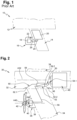
- an aircraft 10 comprises a fuselage 12 , a wing structure 14 and several propulsion units 16 positioned on each side of the fuselage, connected to the wing structure 14 and each comprising a turbomachine 18 .
- the aircraft 10 comprises fuel tanks 20 incorporated into the wing structure 14 and a fuel supply device 22 connecting each turbomachine 18 to a fuel tank 20 .
- the fuel supply device comprises at least a pump 24 and at least a heat exchanger 26 for preheating the fuel.
- This heat exchanger 26 which uses at least a source of heat from the turbomachine 18 , is positioned at the propulsion unit 16 .
- the latter comprises at least one fuel tank positioned in the fuselage and configured to store the hydrogen in the liquid and cryogenic state.
- the aircraft also comprises a hydrogen supply device connecting each turbomachine to a fuel tank and comprising a high-pressure pump and a heat exchanger.
- the high-pressure pump is positioned at the outlet of the fuel tank.
- the heat exchangers are positioned in the vicinity of the turbomachines in the propulsion units.
- the hydrogen supply device comprises pipes to carry the hydrogen at high pressure, in the liquid and cryogenic state, from the high-pressure pump positioned in the fuselage as far as the heat exchanger positioned in one of the propulsion units.
- the pipes are complex double-walled thermally insulated pipes, the space between the two walls being inerted or evacuated.
- Document US2008/006743 discloses an aircraft with a high-flying altitude and long endurance, powered by hydrogen and comprising a tank of cryogenic fluid positioned in the fuselage of the aircraft, the aircraft propulsion system being arranged on the fuselage or on the wing of the aircraft.
- the subject matter of the invention is an aircraft comprising a fuselage, a wing structure, at least one propulsion unit connected to the wing structure and distant from the fuselage, at least one turbomachine running on hydrogen and generating thrust at the propulsion unit, at least one fuel tank positioned in the fuselage, and configured to store hydrogen in the liquid and cryogenic state, and at least one hydrogen supply device connecting the turbomachine and the fuel tank, this hydrogen supply device comprising at least one pump connected to the fuel tank and positioned in the fuselage in the vicinity of the fuel tank as well as at least one hydrogen heating system positioned upstream of the turbomachine.
- the hydrogen heating system is positioned in the fuselage in the vicinity of the pump or in the region of a junction connecting the fuselage and the wing structure.
- This solution makes it possible to reduce the length of the complex double-walled pipes configured to carry the hydrogen in the cryogenic state between the fuel tank, the pump and the hydrogen heating system.
- the hydrogen heating system is separated from the fuel tank by a distance less than 5 m.
- the hydrogen heating system comprises at least a heat exchanger, at least an electrical heating system and/or at least a catalysis-heating system.
- the hydrogen heating system comprises at least a heat exchanger through which a stream of air bled from outside the aircraft passes.
- the hydrogen heating system comprises at least a heat exchanger configured to exchange heat energy between the hydrogen and a heat-transfer fluid coming from at least a source present in the aircraft.
- the hydrogen heating system comprises at least a main heat exchanger configured to exchange heat energy between the hydrogen and an intermediate heat-transfer fluid passing through at least a secondary heat exchanger.
- the hydrogen heating system comprises at least two main heat exchangers arranged in series and configured to exchange heat energy between the hydrogen and the one same intermediate heat-transfer fluid passing through at least one secondary heat exchanger.
- the hydrogen heating system comprises a return circuit configured to tap off some of the heated hydrogen leaving the hydrogen heating system and reintroduce it into the inlet of the hydrogen heating system.
- the propulsion unit comprises a multiblade propeller
- the turbomachine is positioned in the region of a junction connecting the fuselage and the wing structure, the aircraft comprising a mechanical drivetrain connecting the turbomachine and the multiblade propeller.
- the turbomachine comprises a rotor which has an axis of rotation and it is positioned in such a way that this axis of rotation is parallel to a longitudinal axis of the fuselage.
- the hydrogen supply device comprises a first double-walled pipe connecting the fuel tank and the pump and a second double-walled pipe connecting the pump and the hydrogen heating system.
- the hydrogen supply device comprises a third double-walled pipe connecting the hydrogen heating system and the turbomachine.
- the aircraft comprises propulsion units positioned on each side of the fuselage and connected to the wing structure, each propulsion unit being distant from the fuselage and comprising a turbomachine, said aircraft comprising a fuel tank common to said turbomachines and a hydrogen supply device for each turbomachine.
- FIG. 1 is a schematic depiction of part of an aircraft comprising a fuel supply device illustrating one embodiment of the prior art
- FIG. 2 is a schematic depiction of part of an aircraft comprising a hydrogen supply device illustrating one embodiment of the invention
- FIG. 3 is a schematic depiction of a heat exchanger of a hydrogen supply device illustrating one embodiment of the invention
- FIG. 4 is a schematic depiction of a heat exchanger of a hydrogen supply device illustrating another embodiment of the invention
- FIG. 5 is a schematic depiction of a heat exchanger of a hydrogen supply device illustrating another embodiment of the invention
- FIG. 6 is a schematic depiction of a heat exchanger of a hydrogen supply device illustrating another embodiment of the invention.
- FIG. 7 is a schematic depiction of a heat exchanger of a hydrogen supply device illustrating another embodiment of the invention.
- FIG. 8 is a schematic depiction of a heat exchanger of a hydrogen supply device illustrating another embodiment of the invention.
- FIG. 9 is a schematic depiction of part of an aircraft comprising a hydrogen supply device and an offset turbomachine illustrating one embodiment of the invention.
- FIG. 10 is a perspective view of part of an aircraft showing, including hidden detail, an offset turbomachine illustrating one embodiment of the invention.
- an aircraft 30 comprises a fuselage 32 , a wing structure 34 and propulsion units 36 positioned on each side of the fuselage 32 and connected to the wing structure 34 .
- the fuselage 32 is approximately cylindrical and has a longitudinal axis A 32 parallel to the exterior wall of the fuselage 32 .
- the propulsion units 36 are positioned beneath the wing structure 34 . They are distant from the fuselage 32 . In other words, the propulsion units 36 are positioned some distance from the fuselage 32 , which is to say, there is a space between each propulsion unit 36 and the fuselage 32 .
- each propulsion unit 36 comprises a nacelle 38 , a turbomachine 40 positioned in the nacelle 38 and having an output shaft A 40 , a multiblade propeller 42 positioned on the outside of the nacelle 38 and having a rotation shaft A 42 coupled to the output shaft A 40 of the turbomachine 40 .
- the propulsion unit 36 comprises reduction gear 44 positioned inside the nacelle 38 and connecting the rotation shaft A 42 of the multiblade propeller 42 and the output shaft A 40 of the turbomachine 40 .
- the aircraft 30 comprises at least one fuel tank 46 , positioned in the fuselage 32 and configured to store hydrogen in the liquid and cryogenic state, and a hydrogen supply device connecting the turbomachine 40 and the fuel tank 46 .
- the fuel tank 46 has at least one outlet 48 .
- the hydrogen is at a pressure of the order of 3 bar and a temperature of the order of ⁇ 243° C. at the outlet 48 of the fuel tank 46 .
- the aircraft 30 comprises one fuel tank common to a plurality of turbomachines 40 and one hydrogen supply device for each turbomachine 40 .
- the invention is not limited to that configuration.
- the hydrogen supply device comprises at least a pump 50 connected to the outlet 48 of the fuel tank 46 and at least one hydrogen heating system 52 upstream of the turbomachine 40 .
- the pump 50 is a high pressure pump.
- the pump 50 is positioned in the fuselage 32 in the vicinity of the outlet 48 of the fuel tank 46 .
- the pump 50 is positioned a short distance away from the outlet 48 of the fuel tank 46 , for example at a distance of 5 m or less. Because the hydrogen is in the liquid state when it is compressed, this arrangement makes it possible to reduce the energy needed for compressing the hydrogen.
- the hydrogen in the liquid and the cryogenic state is at a pressure of the order of 50 bar at the outlet of the pump 50 .
- the hydrogen heating system 52 is positioned in the fuselage 32 in the vicinity of the pump 50 a short distance from the fuel tank 46 . What is meant by a short distance is that the hydrogen heating system 52 is separated from the fuel tank 46 by a distance of less than 5 m.
- the hydrogen heating system 52 is preferably separated from the fuel tank 46 by a distance of less than 5 m, but could of course be separated from the fuel tank 46 by a distance greater than 5 m.
- the hydrogen heating system 52 is positioned in the region of a junction 72 connecting the fuselage 32 and the wing structure 34 , which is to say, at an interface between the fuselage 32 and the wing structure 34 (wing box) in the vicinity of the pump 50 , a short distance from the fuel tank 46 .
- the hydrogen heating system 52 is configured so that the temperature of the hydrogen leaving it is an optimal temperature for the turbomachine 40 . Thus, on leaving the hydrogen heating system 52 , the hydrogen is in the gaseous state and no longer in the cryogenic state. As an idea of scale, the hydrogen is at a temperature of the order of 27° C. on leaving the hydrogen heating system 52 .
- the hydrogen supply device comprises a first double-walled pipe 54 . 1 connecting the fuel tank 46 and the pump 50 , and a second double-walled pipe 54 . 2 connecting the pump 50 and the hydrogen heating system 52 .
- These first and second double-walled pipes 54 . 1 , 54 . 2 are configured to carry hydrogen in the liquid and cryogenic state.
- the cumulative length of the first and second double-walled pipes 54 . 1 , 54 . 2 is reduced and markedly shorter by comparison with the length of such walls of the prior art, thus limiting the increase in on-board mass.
- the hydrogen supply device comprises a third pipe 56 connecting the hydrogen heating system 52 and the turbomachine 40 and configured to carry hydrogen in the gaseous state.
- the third pipe 56 is a double-walled pipe, different than the first and second double-walled pipes 54 . 1 , 54 . 2 , and simpler, having a mass per unit length that is markedly lower than that of the first and second double-walled pipes 54 . 1 , 54 . 2 .
- this third pipe 56 does not carry a fluid in the cryogenic state, the risks of icing of the aircraft structures that support it are low.
- the hydrogen supply device may comprise a combination of various hydrogen heating systems 52 .
- the hydrogen heating system 52 comprises at least one heat exchanger 58 .
- the hydrogen heating system comprises at least one heat exchanger 58 through which there passes a stream of air bled from outside the aircraft.
- the air stream is carried along a duct 60 connecting an air inlet 62 . 1 configured to bleed the air from outside the fuselage 32 and an air outlet 62 . 2 configured to eject the air to outside the fuselage 32 .
- the hydrogen heating system 52 comprises at least one heat exchanger 58 configured to exchange heat energy between the hydrogen and a heat-transfer gas coming from at least a source present in the aircraft, such as hot air from a turbomachine 40 or from an auxiliary power unit (APU) and used, amongst other things, for air conditioning the cabin of the aircraft.
- a source present in the aircraft such as hot air from a turbomachine 40 or from an auxiliary power unit (APU) and used, amongst other things, for air conditioning the cabin of the aircraft.
- APU auxiliary power unit
- the hydrogen heating system 52 comprises at least one heat exchanger 58 configured to exchange heat energy between the hydrogen and a heat-transfer liquid coming from at least one source present in the aircraft, such as the oil from a turbomachine 40 or from an auxiliary power unit.
- the hydrogen heating system 52 comprises at least one heat exchanger 58 configured to exchange heat energy between the hydrogen and an intermediate heat-transfer fluid coming from at least one other heat exchanger configured to exchange heat energy between the intermediate heat-transfer fluid and a heat-transfer fluid coming from at least one source present in the aircraft, such as hot air or oil coming from a turbomachine 40 or from an auxiliary power unit.
- the hydrogen heating system 52 comprises a combination of several heat exchangers.
- the hydrogen heating system 52 comprises first and second heat exchangers 58 , 58 ′ in series, the first heat exchanger 58 being configured to exchange heat energy between the hydrogen and a heat-transfer fluid, such as oil for example, coming from a turbomachine 40 or from an auxiliary power unit, the second heat exchanger 58 ′ being configured to exchange heat energy between the hydrogen and a heat-transfer fluid, such as hot air for example, coming from a turbomachine 40 or from an auxiliary power unit.
- the hydrogen heating system 52 may comprise a return circuit configured to tap off some of the heated hydrogen at the outlet of the hydrogen heating system 52 and reintroduce the heated hydrogen to the inlet thereof.
- the hydrogen heating system 52 comprises three heat exchangers 58 , 58 ′, 58 ′′ in series, a first heat exchanger 58 configured to exchange heat energy between the hydrogen and a heat-transfer fluid, such as oil for example, coming from a turbomachine 40 or from an auxiliary power unit, a second heat exchanger 58 ′ configured to exchange heat energy between the hydrogen and a heat-transfer fluid, such as hot air for example, coming from a turbomachine 40 or from an auxiliary power unit, a third heat exchanger 58 ′′ configured to exchange heat energy between the hydrogen and a heat-transfer fluid coming from another heat source 64 of the aircraft.
- the hydrogen heating system 52 comprises a return circuit 66 configured to tap off some of the heated hydrogen leaving the hydrogen heating system 52 and reintroduce the heated hydrogen to the inlet thereof.
- the hydrogen heating system 52 comprises first and second main heat exchangers 58 , 58 ′ in series and first and second secondary heat exchangers 68 , 68 ′.
- the first main heat exchanger 58 is configured to exchange heat energy between the hydrogen and a first intermediate heat-transfer fluid 70 coming from the first secondary heat exchanger 68 configured to exchange heat energy between the first intermediate heat-transfer fluid 70 and a heat-transfer fluid, such as oil for example, coming from a turbomachine 40 or from an auxiliary power unit.
- the second main heat exchanger 58 ′ being configured to exchange heat energy between the hydrogen and a second intermediate heat-transfer fluid 70 ′ coming from the second secondary heat exchanger 68 ′ configured to exchange heat energy between the second intermediate heat-transfer fluid 70 ′ and a heat-transfer fluid, such as hot air, coming from a turbomachine 40 or from an auxiliary power unit.
- the hydrogen heating system comprises a return circuit 66 configured to tap off some of the heated hydrogen leaving the hydrogen heating system 52 and reintroduce it to the inlet thereof.
- the hydrogen heating system 52 may comprise three or more main heat exchangers in series each coupled with a secondary heat exchanger.
- a third main heat exchanger is configured to exchange heat energy between the hydrogen and a third intermediate heat-transfer fluid coming from a third secondary heat exchanger configured to exchange heat energy between the third intermediate heat-transfer fluid and a heat-transfer fluid coming from another heat source of the aircraft.
- the hydrogen heating system 52 comprises a main heat exchanger 58 and first and second secondary heat exchangers 68 , 68 ′ in series.
- the main heat exchanger 58 is configured to exchange heat energy between the hydrogen and an intermediate heat-transfer fluid 70 passing through the first and second secondary heat exchangers 68 , 68 ′.
- the first secondary heat exchanger 68 is configured to exchange heat energy between the intermediate heat-transfer fluid 70 and a heat-transfer fluid, such as oil for example, coming from a turbomachine 40 or from an auxiliary power unit.
- the second secondary heat exchanger 68 ′ is configured to exchange heat energy between the intermediate heat-transfer fluid 70 and a heat-transfer fluid, such as hot air for example, coming from a turbomachine 40 or from an auxiliary power unit.
- the hydrogen heating system 52 comprises a return circuit 66 configured to tap off some of the heated hydrogen leaving the main heat exchanger 58 and reintroduce it upstream of the latter.
- the hydrogen heating system 52 may comprise three secondary heat exchangers in series through which there passes an intermediate heat-transfer fluid 70 that passes through the main heat exchanger 58 .
- a third secondary heat exchanger 68 is configured to exchange heat energy between the intermediate heat-transfer fluid and a heat-transfer fluid coming from another heat source of the aircraft.
- the hydrogen heating system 52 comprises a first heat exchanger 58 configured to exchange heat energy between the hydrogen and an intermediate heat-transfer fluid 70 coming from a secondary heat exchanger 68 and a second heat exchanger 58 ′ configured to exchange heat energy between the hydrogen and a heat-transfer fluid, such as hot air for example, coming from a turbomachine 40 or from an auxiliary power unit, the first and second heat exchangers 58 , 58 ′ being arranged in series.
- the secondary heat exchanger 68 is configured to exchange heat energy between the intermediate heat-transfer fluid 70 and a heat-transfer fluid, such as oil for example, coming from a turbomachine 40 or from an auxiliary power unit.
- the hydrogen heating system 52 comprises a return circuit 66 configured to tap off some of the heated hydrogen leaving the hydrogen heating system 52 and reintroduce it to the inlet of the latter.
- the hydrogen heating system 52 comprises at least two main heat exchangers 58 , 58 ′ arranged in series and configured to exchange heat energy between the hydrogen and the one same intermediate heat-transfer fluid 70 passing through at least a secondary heat exchanger 68 .
- the hydrogen heating system 52 comprises first, second and third secondary heat exchangers 68 , 68 ′, 68 ′′ arranged in series and through which there passes the intermediate heat-transfer fluid 70 which passes through the first and second main heat exchangers 58 , 58 ′ in parallel.
- the first secondary heat exchanger 68 is configured to exchange heat energy between the intermediate heat-transfer fluid 70 and a heat-transfer fluid, such as oil for example, coming from a turbomachine 40 or from an auxiliary power unit.
- the second secondary heat exchanger 68 ′ is configured to exchange heat energy between the intermediate heat-transfer fluid 70 and a heat-transfer fluid, such as hot air for example, coming from a turbomachine 40 or from an auxiliary power unit.
- the third secondary heat exchanger 68 ′′ is configured to exchange heat energy between the intermediate heat-transfer fluid 70 and a heat-transfer fluid coming from another heat source 64 of the aircraft.
- the secondary heat exchanger or exchangers may be arranged in the nacelle 38 .
- the hydrogen heating system 52 is an electrical heating system comprising at least one resistive electrical element powered by an electrical source, for example an electric battery or any other electrical source of the aircraft.
- the hydrogen heating system 52 is a heating system employing catalysis, for example consuming hydrogen in order to produce heat.
- the hydrogen heating system 52 comprises at least one heat exchanger, at least one electrical heating system and/or at least one catalysis heating system.
- the turbomachine 40 is not positioned in the nacelle 38 .
- the turbomachine 40 is positioned as close as possible to the fuselage 32 in the region of a junction 72 connecting the fuselage 32 and the wing structure 34 .
- the turbomachine 40 may, as the case may be, be positioned under, in or on the wing structure 34 .
- all the turbomachines 40 coupled to a multiblade propeller 42 are positioned on each side of the fuselage 32 in the junction regions 72 connecting the fuselage 32 and the wing structure 34 .
- the aircraft For each turbomachine 40 positioned in the junction region 72 connecting the fuselage 32 and the wing structure 34 and which is coupled to a multiblade propeller 42 , the aircraft comprises a mechanical driveline 74 connecting the turbomachine 40 and the multiblade propeller 42 and more particularly the reduction gearbox 44 coupled to the multiblade propeller 42 .
- each mechanical driveline 74 comprises at least a transmission shaft 74 . 1 and a coupling mechanism 74 . 2 provided at each end of each transmission shaft 74 . 1 .
- the act of positioning the turbomachine 40 or at least one turbomachine 40 in the junction region 72 connecting the fuselage 32 and the wing structure 34 means that the dimensions of the nacelle 38 and, more particularly, the cross section thereof (perpendicular to the rotation shaft A 42 of the multiblade propeller 42 ) can be reduced, thereby contributing to improving the aerodynamic performance of the aircraft.
- the turbomachine 40 or at least one turbomachine 40 comprises a rotor which has an axis of rotation 76 and it is positioned in such a way that this axis of rotation 76 is parallel to the longitudinal axis A 32 of the fuselage 32 .
- This configuration makes it possible to broaden the scope of options regarding the positioning of the fuel tanks 46 .
- the invention is not restricted to this configuration, it being possible for the turbomachine 40 to be positioned in such a way that the axis of rotation 76 of the rotor thereof is perpendicular to or inclined with respect to the longitudinal axis A 32 of the fuselage 32 .
- the aircraft comprises at least one turbomachine 40 generating thrust at a propulsion unit.
- the turbomachine 40 generates the thrust directly and is positioned in the propulsion unit.
- the turbomachine 40 is coupled to a multiblade propeller incorporated into the propulsion unit and the turbomachine is positioned in the propulsion unit or spaced away therefrom.
Landscapes
- Engineering & Computer Science (AREA)
- Aviation & Aerospace Engineering (AREA)
- Mechanical Engineering (AREA)
- Chemical & Material Sciences (AREA)
- Combustion & Propulsion (AREA)
- General Engineering & Computer Science (AREA)
- Filling Or Discharging Of Gas Storage Vessels (AREA)
- Engine Equipment That Uses Special Cycles (AREA)
Abstract
Description
Claims (11)
Applications Claiming Priority (2)
| Application Number | Priority Date | Filing Date | Title |
|---|---|---|---|
| FR2108416 | 2021-08-03 | ||
| FR2108416 | 2021-08-03 |
Publications (2)
| Publication Number | Publication Date |
|---|---|
| US20230045036A1 US20230045036A1 (en) | 2023-02-09 |
| US11840962B2 true US11840962B2 (en) | 2023-12-12 |
Family
ID=77913263
Family Applications (1)
| Application Number | Title | Priority Date | Filing Date |
|---|---|---|---|
| US17/878,331 Active US11840962B2 (en) | 2021-08-03 | 2022-08-01 | Aircraft comprising a hydrogen supply device incorporating a hydrogen heating system positioned in the fuselage of the aircraft |
Country Status (3)
| Country | Link |
|---|---|
| US (1) | US11840962B2 (en) |
| EP (1) | EP4129828B1 (en) |
| CN (1) | CN115703541A (en) |
Families Citing this family (2)
| Publication number | Priority date | Publication date | Assignee | Title |
|---|---|---|---|---|
| US12017789B2 (en) * | 2021-10-05 | 2024-06-25 | General Electric Company | Onboard liquid hydrogen storage for a hydrogen aircraft |
| GB202408332D0 (en) * | 2024-06-11 | 2024-07-24 | Rolls Royce Plc | Aircraft fuel system |
Citations (2)
| Publication number | Priority date | Publication date | Assignee | Title |
|---|---|---|---|---|
| US20080006743A1 (en) | 2006-07-05 | 2008-01-10 | Miller Gerald D | Long endurance hydrogen powered vehicle |
| US20130255281A1 (en) * | 2012-03-29 | 2013-10-03 | General Electric Company | System and method for cooling electrical components |
-
2022
- 2022-07-08 EP EP22183709.9A patent/EP4129828B1/en active Active
- 2022-08-01 US US17/878,331 patent/US11840962B2/en active Active
- 2022-08-02 CN CN202210921233.XA patent/CN115703541A/en active Pending
Patent Citations (2)
| Publication number | Priority date | Publication date | Assignee | Title |
|---|---|---|---|---|
| US20080006743A1 (en) | 2006-07-05 | 2008-01-10 | Miller Gerald D | Long endurance hydrogen powered vehicle |
| US20130255281A1 (en) * | 2012-03-29 | 2013-10-03 | General Electric Company | System and method for cooling electrical components |
Non-Patent Citations (1)
| Title |
|---|
| French Search Report; priority document. |
Also Published As
| Publication number | Publication date |
|---|---|
| CN115703541A (en) | 2023-02-17 |
| EP4129828B1 (en) | 2025-12-31 |
| US20230045036A1 (en) | 2023-02-09 |
| EP4129828A1 (en) | 2023-02-08 |
Similar Documents
| Publication | Publication Date | Title |
|---|---|---|
| US11286853B2 (en) | Cooling system | |
| US12162611B2 (en) | Aircraft propulsion system | |
| US10823066B2 (en) | Thermal management system | |
| US9765691B2 (en) | Turbine engine assembly and dual fuel aircraft system | |
| US11840962B2 (en) | Aircraft comprising a hydrogen supply device incorporating a hydrogen heating system positioned in the fuselage of the aircraft | |
| US20140182264A1 (en) | Aircraft engine systems and methods for operating same | |
| US10184614B2 (en) | Method for managing LNG boil-off and LNG boil-off management assembly | |
| US12479591B2 (en) | System for conditioning fuel for supplying an aircraft turbomachine, aircraft and method of use | |
| US20220267021A1 (en) | Aircraft having an engine and a cooling system based on dihydrogen | |
| EP4215730B1 (en) | Hydrogen powered geared turbo fan engine with an off-set reduced core | |
| JP2016512862A (en) | Energy efficient controlled cryofuel evaporation for aircraft engines | |
| JP2016509645A (en) | Temperature and actuation control system and method for controlling aircraft fluid temperature | |
| CN105026726A (en) | Turbine engine assembly comprising a cryogenic fuel system | |
| EP2938850A1 (en) | Cryogenic fuel system and method for delivering fuel in an aircraft | |
| JP6031097B2 (en) | Aircraft engine fuel system and method of operating the same | |
| US20240166356A1 (en) | Multifunctional air system for fuel cell powered aircraft |
Legal Events
| Date | Code | Title | Description |
|---|---|---|---|
| FEPP | Fee payment procedure |
Free format text: ENTITY STATUS SET TO UNDISCOUNTED (ORIGINAL EVENT CODE: BIG.); ENTITY STATUS OF PATENT OWNER: LARGE ENTITY |
|
| STPP | Information on status: patent application and granting procedure in general |
Free format text: DOCKETED NEW CASE - READY FOR EXAMINATION |
|
| AS | Assignment |
Owner name: AIRBUS OPERATIONS SAS, FRANCE Free format text: ASSIGNMENT OF ASSIGNORS INTEREST;ASSIGNORS:CZAPLA, LIONEL;ABELE, ANTOINE;THUBERT, BENJAMIN;AND OTHERS;SIGNING DATES FROM 20220708 TO 20220801;REEL/FRAME:061343/0122 Owner name: AIRBUS SAS, FRANCE Free format text: ASSIGNMENT OF ASSIGNORS INTEREST;ASSIGNORS:CZAPLA, LIONEL;ABELE, ANTOINE;THUBERT, BENJAMIN;AND OTHERS;SIGNING DATES FROM 20220708 TO 20220801;REEL/FRAME:061343/0122 |
|
| STPP | Information on status: patent application and granting procedure in general |
Free format text: NON FINAL ACTION MAILED |
|
| STPP | Information on status: patent application and granting procedure in general |
Free format text: RESPONSE TO NON-FINAL OFFICE ACTION ENTERED AND FORWARDED TO EXAMINER |
|
| STPP | Information on status: patent application and granting procedure in general |
Free format text: NOTICE OF ALLOWANCE MAILED -- APPLICATION RECEIVED IN OFFICE OF PUBLICATIONS |
|
| STPP | Information on status: patent application and granting procedure in general |
Free format text: PUBLICATIONS -- ISSUE FEE PAYMENT RECEIVED |
|
| STPP | Information on status: patent application and granting procedure in general |
Free format text: PUBLICATIONS -- ISSUE FEE PAYMENT VERIFIED |
|
| STCF | Information on status: patent grant |
Free format text: PATENTED CASE |