US11836948B2 - Image calibration method and image calibration device - Google Patents
Image calibration method and image calibration device Download PDFInfo
- Publication number
- US11836948B2 US11836948B2 US17/228,734 US202117228734A US11836948B2 US 11836948 B2 US11836948 B2 US 11836948B2 US 202117228734 A US202117228734 A US 202117228734A US 11836948 B2 US11836948 B2 US 11836948B2
- Authority
- US
- United States
- Prior art keywords
- image
- overlapping region
- value
- base color
- pixel unit
- Prior art date
- Legal status (The legal status is an assumption and is not a legal conclusion. Google has not performed a legal analysis and makes no representation as to the accuracy of the status listed.)
- Active, expires
Links
Images


Classifications
-
- G—PHYSICS
- G06—COMPUTING OR CALCULATING; COUNTING
- G06T—IMAGE DATA PROCESSING OR GENERATION, IN GENERAL
- G06T7/00—Image analysis
- G06T7/80—Analysis of captured images to determine intrinsic or extrinsic camera parameters, i.e. camera calibration
-
- G—PHYSICS
- G06—COMPUTING OR CALCULATING; COUNTING
- G06T—IMAGE DATA PROCESSING OR GENERATION, IN GENERAL
- G06T5/00—Image enhancement or restoration
- G06T5/50—Image enhancement or restoration using two or more images, e.g. averaging or subtraction
-
- G—PHYSICS
- G06—COMPUTING OR CALCULATING; COUNTING
- G06T—IMAGE DATA PROCESSING OR GENERATION, IN GENERAL
- G06T7/00—Image analysis
- G06T7/90—Determination of colour characteristics
-
- G—PHYSICS
- G06—COMPUTING OR CALCULATING; COUNTING
- G06T—IMAGE DATA PROCESSING OR GENERATION, IN GENERAL
- G06T7/00—Image analysis
- G06T7/97—Determining parameters from multiple pictures
-
- G—PHYSICS
- G06—COMPUTING OR CALCULATING; COUNTING
- G06T—IMAGE DATA PROCESSING OR GENERATION, IN GENERAL
- G06T2207/00—Indexing scheme for image analysis or image enhancement
- G06T2207/10—Image acquisition modality
- G06T2207/10024—Color image
-
- G—PHYSICS
- G06—COMPUTING OR CALCULATING; COUNTING
- G06T—IMAGE DATA PROCESSING OR GENERATION, IN GENERAL
- G06T2207/00—Indexing scheme for image analysis or image enhancement
- G06T2207/20—Special algorithmic details
- G06T2207/20212—Image combination
- G06T2207/20221—Image fusion; Image merging
Definitions
- the present invention relates to an image calibration method and an image calibration device, and more particularly, to an image calibration method and a related image calibration device capable of effectively increasing image feature continuity.
- the conventional surveillance camera has several image receivers adapted to capture a plurality of small dimensional monitoring images in different fields of view, and the plurality of small dimensional monitoring images are stitched to form a panoramic image containing a large dimensional scene.
- the plurality of small dimensional monitoring images is partly overlapped with each other.
- An overlapped region between two adjacent monitoring images is detected to search at least one feature that appears in the overlapped region of the two adjacent monitoring images, and the feature is used to stitch the adjacent monitoring images.
- each image receiver of the conventional surveillance camera has unique hardware and software setting, so that the plurality of small dimensional monitoring images captured by the image receivers cannot have the same image parameters in luminance, contrast and saturation even if all the image receivers are designed by similar hardware and software.
- a vestige of stitching line is clearly found in the panoramic image generated by the small dimensional monitoring images via conventional image stitching technology, and results in inartistic appearance of the panoramic image.
- Design of an image calibration method capable of eliminating the stitching vestige and increasing image feature continuity is an important issue in the surveillance camera industry.
- the present invention provides an image calibration method and a related image calibration device capable of effectively increasing image feature continuity for solving above drawbacks.
- an image calibration method includes comparing a first image with a second image to acquire a first overlapping region of the first image and a second overlapping region of the second image, analyzing color distribution of the first overlapping region to acquire at least one first base color value, analyzing color distribution of the second overlapping region to acquire at least one second base color value, setting a ratio of the at least one first base color value to the at least one second base color value as an luminance compensation value when the at least one first base color value is greater than the at least one second base color value, and utilizing the luminance compensation value to adjust pixels of the second image.
- the first overlapping region is overlapped with the second overlapping region
- an image calibration method includes comparing a first image with a second image to acquire a first overlapping region of the first image and a second overlapping region of the second image, computing a first aberration ratio of two first base color values with different color inside the first overlapping region, computing a second aberration ratio of two second base color values with different color inside the second overlapping region, acquiring an aberration compensation value via the first aberration ratio and the second aberration ratio, and utilizing the aberration compensation value to respectively adjust at least one first selected base color value from a plurality of first base color values contained by the first image and at least one second selected base color value from a plurality of second base color values contained by the second image.
- the first selected base color and the second selected base color value have the same color, and the first overlapping region is overlapped with the second overlapping region
- an image calibration device includes an image receiver and an operational processor.
- the image receiver is adapted to receive a first image and a second image.
- the operational processor is electrically connected to the image receiver, and adapted to compare a first image with a second image to acquire a first overlapping region of the first image and a second overlapping region of the second image, analyze color distribution of the first overlapping region to acquire at least one first base color value, analyze color distribution of the second overlapping region to acquire at least one second base color value, set a ratio of the at least one first base color value to the at least one second base color value as an luminance compensation value when the at least one first base color value is greater than the at least one second base color value, and utilize the luminance compensation value to adjust pixels of the second image.
- the first overlapping region is overlapped with the second overlapping region.
- an image calibration device includes an image receiver and an operational processor.
- the image receiver is adapted to receive a first image and a second image.
- the operational processor is electrically connected to the image receiver, and adapted to compare a first image with a second image to acquire a first overlapping region of the first image and a second overlapping region of the second image, compute a first aberration ratio of two first base color values with different color inside the first overlapping region, compute a second aberration ratio of two second base color values with different color inside the second overlapping region, acquire an aberration compensation value via the first aberration ratio and the second aberration ratio, and utilize the aberration compensation value to respectively adjust at least one first selected base color value from a plurality of first base color values contained by the first image and at least one second selected base color value from a plurality of second base color values contained by the second image.
- the first overlapping region is overlapped with the second overlapping region, and the first selected base color and the second selected base color value have the same color.
- the image calibration method and the image calibration device of the present invention can acquire the overlapping regions inside the two images, and analyze the color distribution within the overlapping regions, so as to regulate the base color value of all pixels inside the two images in accordance with the ratio of two identical base color values inside different overlapping regions or in accordance with the ratio of two different base color values inside the same overlapping regions, for setting parameter unity in the stitching image.
- the embodiment disclosed in the present invention can adjust the image luminance and then the image aberration, or only adjust the image luminance, or only adjust the image aberration, or compensate the image luminance and/or the image aberration via other image parameters which are useful for eliminating the stitching vestige.
- the present invention can calibrate the luminance and the aberration of a center and surroundings inside the stitching image after two, and then execute modification of the luminance and the aberration based on the calibrated stitching image for effectively eliminating the stitching vestige.
- FIG. 1 is a functional block diagram of an image calibration device according to an embodiment of the present invention.
- FIG. 2 is a flow chart of an image calibration method according to the embodiment of the present invention.
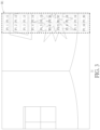
- FIG. 3 and FIG. 4 are diagrams of a first image and a second image according to the embodiment of the present invention.
- FIG. 5 is a diagram of the stitching image according to the embodiment of the present invention.
- FIG. 6 is a flow chart of computing the luminance compensation value according to the embodiment of the present invention.
- FIG. 7 is a diagram of color distribution of the first overlapping region and the second overlapping region in luminance adjustment according to the embodiment of the present invention.
- FIG. 8 is a flow chart of computing the aberration compensation value according to the embodiment of the present invention.
- FIG. 9 is a diagram of the color distribution of the first overlapping region and the second overlapping region in aberration adjustment according to the embodiment of the present invention.
- FIG. 1 is a functional block diagram of an image calibration device 10 according to an embodiment of the present invention.
- FIG. 2 is a flow chart of an image calibration method according to the embodiment of the present invention.
- the image calibration device 10 can be a surveillance apparatus used to detect a surveillance region with large dimensions.
- the image calibration device 10 can capture several surveillance images with different fields of view, or receive several surveillance images captured by an external camera, and the surveillance image can be stitched tor form a stitching image with a panoramic characteristic.
- the image calibration device 10 can include an image receiver 12 and an operational processor 14 .
- the image receiver 12 may capture a plurality of images, or receive the plurality of images whose surveillance regions are partly overlapped in a wireless manner or in a wire manner.
- the operational processor 14 can be electrically connected to the image receiver 12 , and execute the image calibration method to remove a stitching vestige for increasing brightness and/or color saturation of the stitching image.
- FIG. 3 and FIG. 4 are diagrams of a first image I 1 and a second image I 2 according to the embodiment of the present invention.
- FIG. 5 is a diagram of the stitching image Is according to the embodiment of the present invention.
- the image calibration device 10 can stitch and calibrate two images having the surveillance regions adjacent to and partly overlapped with each other; for example, the first image I 1 and the second image I 2 can be stitched to form the stitching image Is.
- step S 100 can be executed to compare the first image I 1 with the second image I 2 to acquire a first overlapping region R 1 and a second overlapping region R 2 .
- the first overlapping region R 1 of the first image I 1 can be overlapped with the second overlapping region R 2 of the second image I 2 .
- step S 102 can be executed to gather statistical information of the first overlapping region R 1 and the second overlapping region R 2 for computing a compensation value of image parameters.
- the said image parameters can be the brightness or the color saturation of the image, or any parameter capable of eliminating the stitching vestige, which depends on a design demand.
- step S 104 can be executed to analyze an overlapped scale of the first overlapping region R 1 and the second overlapping region R 2 for setting a confidence index. If the confidence index is smaller than a first predefined threshold, the overlapped scale and a stitching efficacy of the first image I 1 and the second image I 2 are interpreted as being unacceptable, and step S 106 can be executed to abandon image calibration.
- step S 108 and step S 110 can be executed to calibrate the image parameter compensation value via the confidence index, and then calibrate pixels inside the first image I 1 and/or the second image I 2 via the image parameter compensation value, so as to eliminate the stitching vestige on the panoramic image for preferred stitching continuity between the first image I 1 and the second image I 2 .
- Execution of setting the confidence index is an optional step, and therefore step S 100 may be executed after execution of step S 102 , which means the image parameter compensation value can be computed and then directly used to adjust the pixels of the first image I 1 and/or the second image I 2 .
- the confidence index can be further compared with a second predefined threshold, and an adjustment scale of the image parameter compensation value affected by the confidence index can be considered by the overlapped scale of the first overlapping region R 1 and the second overlapping region R 2 , which may be resulted from a comparison result between the confidence index and the second predefined threshold.
- the image calibration method may not execute stitching and calibration of the first image I 1 and the second image I 2 ; in the meantime, the overlapped scale (which means the said twenty percent) can be interpreted as the first predefined threshold.
- the overlapped scale of the first overlapping region R 1 and the second overlapping region R 2 may conform to a predefined calibration standard but still lacks for image quality, so that the image calibration method can set the confidence index as a low weighting value, and the image parameter compensation value can be regulated by the low weighting value to be a final compensation value of the first image I 1 and/or the second image I 2 ; meanwhile, the overlapped scale (which means the said fifty percent) can be interpreted as the second predefined threshold.
- the overlapped scale of the first overlapping region R 1 and the second overlapping region R 2 may conform to an optimal calibration standard, so that the image calibration method can set the confidence index as a high weighting value, and the image parameter compensation value can be regulated by the high weighting value to be the final compensation value of the first image I 1 and/or the second image I 2 .
- the image calibration method can compute one or several first computed values about any first pixel unit (such as the pixel unit P 1 _ 3 shown in FIG. 3 ) and an adjacent first pixel unit (such as the pixels units P 1 _ 2 , P 1 _ 4 , P 1 _ 12 , P 1 _ 13 and P 1 _ 14 shown in FIG. 3 ) inside the first overlapping region R 1 , and further compute one or several second computed values about a second pixel unit whose position corresponds to position of the foresaid first pixel unit (such as the pixel unit P 2 _ 3 shown in FIG.
- the first computed value can be a ratio of the central first pixel unit (such as the pixel unit P 1 _ 3 ) to the surrounding first pixel unit (such as the pixel units P 1 _ 2 , P 1 _ 4 , P 1 _ 12 , P 1 _ 13 and P 1 _ 14 ); accordingly, the second computed value can be acquired by the same computation.
- the first computed value and the second computed value are not limited to the foresaid ratio of two pixel units, and may be another ratio of one weighted pixel unit to another weighted pixel unit, or a difference value between the two pixel units, which depends on the design demand.
- first computed values such as the ratio of the pixel unit P 1 _ 3 to the pixel unit P 1 _ 4
- second computed value such as the ratio of the pixel unit P 2 _ 3 to the pixel unit P 2 _ 4
- the first pixel unit and the second pixel unit can respectively be one single pixel point inside the first image I 1 and the second image I 2 , or can be a pixel block composed of several pixel points inside the first image I 1 and the second image I 2 ; the image calibration device 10 can define a range of the pixel unit in accordance with demands of a computation speed and an accuracy.
- the image calibration method can compute the number of the first pixel unit which conforms to a condition of the coordinates of the first pixel unit inside the first overlapping region R 1 being matched with the coordinates of the second pixel unit inside the second overlapping region R 2 .
- the first overlapping region R 1 may have twenty first pixel units P 1 _ 1 ⁇ P 1 _ 20
- the second overlapping region R 2 may have twenty second pixel units P 2 _ 1 ⁇ P 2 _ 20 .
- the image calibration method does not execute the stitching and calibration of the first image I 1 and the second image I 2 .
- the confidence index can be the low weighting value accordingly set as 0.4; if sixteen sets of the first pixel unit and the second pixel unit conform to the said condition, the overlapped scale of the first overlapping region R 1 and the second overlapping region R 2 is higher than fifty percent, the confidence index can be the high weighting value accordingly set as 0.8.
- the image calibration method of the present invention can set the confidence index as the low weighting value with an invariable numeral (such as the value 0.5) when the overlapped scale is higher than the first predefined threshold and lower than the second predefined threshold, and further can set the confidence index as the high weighting value with another invariable numeral (such as the value 1.0) when the overlapped scale is higher than the second predefined threshold, which depends on the design demand, and a detailed description is omitted herein for simplicity.
- an invariable numeral such as the value 0.5
- another invariable numeral such as the value 1.0
- Step S 102 can include computation of an luminance compensation value and an aberration compensation value.
- FIG. 6 is a flow chart of computing the luminance compensation value according to the embodiment of the present invention.
- FIG. 7 is a diagram of color distribution of the first overlapping region R 1 and the second overlapping region R 2 in luminance adjustment according to the embodiment of the present invention.
- step S 200 and step S 202 can be executed to analyze the color distribution of the first overlapping region R 1 for acquiring at least one first base color value, and analyze the color distribution of the second overlapping region R 2 for acquiring at least one second base color value.
- step S 204 and S 206 can be executed to compare the first base color value with the second base color value, and set a ratio of the first base color value to the second base color value as the luminance compensation value if the first base color value is greater than the second base color value.
- the first base color value can be a dividend
- the second base color value can be a divisor.
- the luminance compensation value can be applied to step S 110 for adjusting the pixels inside the second image I 2 .
- the second red color value of the second overlapping region R 2 or the second image 12 can be regulated from a value 72 to another value 86 (which is a product of the value 72 and the ratio 1.2) via the luminance compensation value, and the second blue color value of the second overlapping region R 2 or the second image 12 can be adjusted from a value 120 to another value 144 (which is a product of the value 120 and the ratio 1.2) via the luminance compensation value.
- the first base color value and the second base color value further can be luminance values computed by the red color value, the green color value and the blue color value via specific proportion.
- the first base color value and the second base color value may be defined as luminance (Luma, Y), and the luminance Y can be computed by three base color values and formula 1.
- Y 0.299 ⁇ R+ 0.587 ⁇ G+ 0.114 ⁇ B Formula 1
- FIG. 8 is a flow chart of computing the aberration compensation value according to the embodiment of the present invention.
- FIG. 9 is a diagram of the color distribution of the first overlapping region R 1 and the second overlapping region R 2 in aberration adjustment according to the embodiment of the present invention.
- step S 300 and step S 302 can be executed to compute a first aberration ratio of one first base color value to another first base color value inside the first overlapping region R 1 , and further to compute a second aberration ratio of one second base color value to another second base color value inside the second overlapping region R 2 .
- the first overlapping region R 1 can have three first base color values
- the second overlapping region R 2 can have three second base color values, such as the red color value, the green color value and the blue color value.
- step S 304 can be executed to compute the aberration compensation value via the first aberration ratio and the second aberration ratio.
- the aberration compensation value may be an average value or any other possible transformed value of the two aberration ratios, which depends on an actual demand. Accordingly, the aberration compensation value can be applied to step S 110 for adjusting the pixels inside the first image I 1 and the second image I 2 .
- the foresaid one first base color value and the foresaid one second base color value have the same color.
- the foresaid another first base color value and the foresaid another second base color value have the same color.
- the present invention preferably may compute an aberration ratio of the green color value to the selected red color value or to the selected blue color value inside the first overlapping region R 1 and the second overlapping region R 2 , which depends on the actual demand. As an example shown in FIG.
- the aberration compensation value can be used to adjust the base color value of all pixels inside the first image I 1 and the second image I 2 ; for example, the first red color value of each pixel inside the first image I 1 and the second red color value of each pixel inside the second image I 2 can be regulated by the aberration compensation value.
- the first blue color value of each pixel inside the first image I 1 and the second blue color value of each pixel inside the second image I 2 can be regulated by the related aberration compensation value computed in the same manner.
- the blue color value and other color value of all pixels inside the first image I 1 and the second image I 2 can be regulated in an above-mentioned manner.
- the base color values of the present invention are not limited to the foresaid red, green and blue color.
- the present invention can choose all pixels inside the first overlapping region R 1 and the second overlapping region R 2 for base color distribution statistics, or choose and utilizes some first pixel units inside the first overlapping region R 1 and some second pixel units inside the second overlapping region R 2 which conform to an overlapped condition for the base color distribution statistics.
- Application of choosing pixels for the base color distribution statistics is not limited to the above-mentioned embodiments, and depends on the design demand.
- the image calibration method and the image calibration device of the present invention can acquire the overlapping regions inside the two images, and analyze the color distribution within the overlapping regions, so as to regulate the base color value of all pixels inside the two images in accordance with the ratio of two identical base color values inside different overlapping regions or in accordance with the ratio of two different base color values inside the same overlapping regions, for setting parameter unity in the stitching image.
- the embodiment disclosed in the present invention can adjust the image luminance and then the image aberration, or only adjust the image luminance, or only adjust the image aberration, or compensate the image luminance and/or the image aberration via other image parameters which are useful for eliminating the stitching vestige.
- the present invention can calibrate the luminance and the aberration of a center and surroundings inside the stitching image after two, and then execute modification of the luminance and the aberration based on the calibrated stitching image for effectively eliminating the stitching vestige.
Landscapes
- Engineering & Computer Science (AREA)
- Physics & Mathematics (AREA)
- General Physics & Mathematics (AREA)
- Theoretical Computer Science (AREA)
- Computer Vision & Pattern Recognition (AREA)
- Image Processing (AREA)
Abstract
Description
Y=0.299×R+0.587×G+0.114×
Claims (20)
Applications Claiming Priority (2)
| Application Number | Priority Date | Filing Date | Title |
|---|---|---|---|
| TW109113997 | 2020-04-27 | ||
| TW109113997A TWI760733B (en) | 2020-04-27 | 2020-04-27 | Image calibration method and image calibration device |
Publications (2)
| Publication Number | Publication Date |
|---|---|
| US20210335009A1 US20210335009A1 (en) | 2021-10-28 |
| US11836948B2 true US11836948B2 (en) | 2023-12-05 |
Family
ID=78222606
Family Applications (1)
| Application Number | Title | Priority Date | Filing Date |
|---|---|---|---|
| US17/228,734 Active 2041-12-02 US11836948B2 (en) | 2020-04-27 | 2021-04-13 | Image calibration method and image calibration device |
Country Status (2)
| Country | Link |
|---|---|
| US (1) | US11836948B2 (en) |
| TW (1) | TWI760733B (en) |
Families Citing this family (2)
| Publication number | Priority date | Publication date | Assignee | Title |
|---|---|---|---|---|
| EP3922168A1 (en) * | 2020-06-10 | 2021-12-15 | Koninklijke Philips N.V. | Determining intensity distributions |
| US20240430575A1 (en) * | 2021-09-02 | 2024-12-26 | Nippon Telegraph And Telephone Corporation | Panorama image generator, method and program |
Citations (8)
| Publication number | Priority date | Publication date | Assignee | Title |
|---|---|---|---|---|
| US20150103157A1 (en) * | 2013-10-11 | 2015-04-16 | National Chung Cheng University | Color degradation compensation method |
| CN105894449A (en) | 2015-11-11 | 2016-08-24 | 乐卡汽车智能科技(北京)有限公司 | Method and system for overcoming abrupt color change in image fusion processes |
| US9838614B1 (en) * | 2016-06-20 | 2017-12-05 | Amazon Technologies, Inc. | Multi-camera image data generation |
| US20170352138A1 (en) * | 2016-06-03 | 2017-12-07 | Xiaoyi Technology Co., Ltd. | Global adjustment of luminance and chrominance consistency among multiple images |
| US20180082454A1 (en) * | 2016-09-19 | 2018-03-22 | Qualcomm Incorporated | Color normalization for a multi-camera system |
| CN109672847A (en) | 2017-10-13 | 2019-04-23 | 李玉卓 | Intelligent safety defense monitoring system based on image recognition technology |
| US20190356873A1 (en) * | 2018-05-21 | 2019-11-21 | Gopro, Inc. | Image signal processing for reducing lens flare |
| US20210243368A1 (en) * | 2018-04-26 | 2021-08-05 | Tenntwo Co., Ltd. | Wide-angle image providing method |
-
2020
- 2020-04-27 TW TW109113997A patent/TWI760733B/en active
-
2021
- 2021-04-13 US US17/228,734 patent/US11836948B2/en active Active
Patent Citations (8)
| Publication number | Priority date | Publication date | Assignee | Title |
|---|---|---|---|---|
| US20150103157A1 (en) * | 2013-10-11 | 2015-04-16 | National Chung Cheng University | Color degradation compensation method |
| CN105894449A (en) | 2015-11-11 | 2016-08-24 | 乐卡汽车智能科技(北京)有限公司 | Method and system for overcoming abrupt color change in image fusion processes |
| US20170352138A1 (en) * | 2016-06-03 | 2017-12-07 | Xiaoyi Technology Co., Ltd. | Global adjustment of luminance and chrominance consistency among multiple images |
| US9838614B1 (en) * | 2016-06-20 | 2017-12-05 | Amazon Technologies, Inc. | Multi-camera image data generation |
| US20180082454A1 (en) * | 2016-09-19 | 2018-03-22 | Qualcomm Incorporated | Color normalization for a multi-camera system |
| CN109672847A (en) | 2017-10-13 | 2019-04-23 | 李玉卓 | Intelligent safety defense monitoring system based on image recognition technology |
| US20210243368A1 (en) * | 2018-04-26 | 2021-08-05 | Tenntwo Co., Ltd. | Wide-angle image providing method |
| US20190356873A1 (en) * | 2018-05-21 | 2019-11-21 | Gopro, Inc. | Image signal processing for reducing lens flare |
Also Published As
| Publication number | Publication date |
|---|---|
| TW202141976A (en) | 2021-11-01 |
| TWI760733B (en) | 2022-04-11 |
| US20210335009A1 (en) | 2021-10-28 |
Similar Documents
| Publication | Publication Date | Title |
|---|---|---|
| CN110136071B (en) | An image processing method, device, electronic device and storage medium | |
| CN112911174B (en) | Image bad point cluster correction method, computer device and computer readable storage medium | |
| CN112752023B (en) | Image adjusting method and device, electronic equipment and storage medium | |
| US8830341B2 (en) | Selection of an optimum image in burst mode in a digital camera | |
| CN101288103B (en) | Methods and apparatus for image processing, for color classification, and for skin color detection | |
| CN100551081C (en) | A kind of method and device of realizing white balance correction | |
| CN109983401B (en) | Camera Assisted Automatic Screen Fitting | |
| US10699359B2 (en) | Parameter adjustments based on strength change | |
| EP2424248A2 (en) | Image processing device, image processing method, and program | |
| US10430934B2 (en) | Image stitching method and image stitching device | |
| US8854511B2 (en) | Apparatus and method for image processing and storage medium, and image pickup apparatus | |
| US20100195902A1 (en) | System and method for calibration of image colors | |
| US11836948B2 (en) | Image calibration method and image calibration device | |
| CN115065814B (en) | Screen color accuracy detection method and device | |
| CN114866754B (en) | Automatic white balance method and device, computer readable storage medium and electronic equipment | |
| CN112669758A (en) | Display screen correction method, device, system and computer readable storage medium | |
| TW201830337A (en) | Method and apparatus for performing automatic white balance on images | |
| CN114219723A (en) | Image enhancement method, image enhancement device and computer readable storage medium | |
| US20250117877A1 (en) | Fisheye image processing method, electronic device, and computer-readable storage medium | |
| CN114374793A (en) | Exposure control method, device, equipment and storage medium | |
| CN114930381B (en) | Image processing method, device, electronic equipment and storage medium | |
| US20210201449A1 (en) | Method for determining moire pattern, method for suppressing moire pattern and circuit system thereof | |
| CN114866755B (en) | Automatic white balance method, device and computer storage medium, electronic equipment | |
| CN115334295A (en) | Image white balance processing method and electronic equipment | |
| US9041815B2 (en) | Digital camera imaging evaluation module |
Legal Events
| Date | Code | Title | Description |
|---|---|---|---|
| AS | Assignment |
Owner name: VIVOTEK INC., TAIWAN Free format text: ASSIGNMENT OF ASSIGNORS INTEREST;ASSIGNORS:KAO, CHUNG-YI;CHEN, SHIH-HSUAN;SIGNING DATES FROM 20210203 TO 20210205;REEL/FRAME:055897/0721 |
|
| FEPP | Fee payment procedure |
Free format text: ENTITY STATUS SET TO UNDISCOUNTED (ORIGINAL EVENT CODE: BIG.); ENTITY STATUS OF PATENT OWNER: LARGE ENTITY |
|
| STPP | Information on status: patent application and granting procedure in general |
Free format text: DOCKETED NEW CASE - READY FOR EXAMINATION |
|
| STPP | Information on status: patent application and granting procedure in general |
Free format text: FINAL REJECTION MAILED |
|
| STPP | Information on status: patent application and granting procedure in general |
Free format text: DOCKETED NEW CASE - READY FOR EXAMINATION |
|
| STPP | Information on status: patent application and granting procedure in general |
Free format text: NOTICE OF ALLOWANCE MAILED -- APPLICATION RECEIVED IN OFFICE OF PUBLICATIONS |
|
| STPP | Information on status: patent application and granting procedure in general |
Free format text: PUBLICATIONS -- ISSUE FEE PAYMENT RECEIVED |
|
| STPP | Information on status: patent application and granting procedure in general |
Free format text: PUBLICATIONS -- ISSUE FEE PAYMENT VERIFIED |
|
| STCF | Information on status: patent grant |
Free format text: PATENTED CASE |