US118285A - Improvement in safety-frogs for railways - Google Patents
Improvement in safety-frogs for railways Download PDFInfo
- Publication number
- US118285A US118285A US118285DA US118285A US 118285 A US118285 A US 118285A US 118285D A US118285D A US 118285DA US 118285 A US118285 A US 118285A
- Authority
- US
- United States
- Prior art keywords
- bar
- frog
- rails
- frogs
- yoke
- Prior art date
- Legal status (The legal status is an assumption and is not a legal conclusion. Google has not performed a legal analysis and makes no representation as to the accuracy of the status listed.)
- Expired - Lifetime
Links
- 241000269350 Anura Species 0.000 description 2
- 238000010276 construction Methods 0.000 description 2
- 230000004048 modification Effects 0.000 description 2
- 238000012986 modification Methods 0.000 description 2
- 240000000233 Melia azedarach Species 0.000 description 1
- 238000013459 approach Methods 0.000 description 1
Images

Classifications
-
- E—FIXED CONSTRUCTIONS
- E01—CONSTRUCTION OF ROADS, RAILWAYS, OR BRIDGES
- E01B—PERMANENT WAY; PERMANENT-WAY TOOLS; MACHINES FOR MAKING RAILWAYS OF ALL KINDS
- E01B7/00—Switches; Crossings
- E01B7/10—Frogs
- E01B7/14—Frogs with movable parts
Definitions
- My invention consists of a lateral shifting-bar, pivoted at one end to a cross-tie of the track and at the other to a yoke connecting the winged rails of the frog, and carrying between these points an ellipsoid device arranged to receive the lateral action of the langes of the wheels approaching thefrog from either track so as to shift the win ged rails in connection with the fixed point of the frog,
- My invention also consists of a coupling-arm or yoke made in twoV sections locked to each other for connecting the curved ends of the winged rails, as hereinafter described.
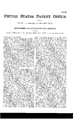
- Figure l represents a plan of a portion of the main railway track with my improved safety-frog applied thereto and set for the siding, the cars moving in the direction of the arrow.
- Fig. 2 represents the divided coupling-yoke of the curved ends of the wing-rails.
- Fig. 3 represents a section of baseplate, wing-rails, and the coupling-yoke to which the shifting-bar is attached.
- Fig. 4 represents a modification of the manner of attaching the shifting-bar to the wing-rails.
- Fig. 5 shows the socket for the pivot of the shifting-bar.
- the main rails A and the siding rails B are arranged in relation to the frog in the usual or any approved way.
- the base-plate O and the point D of the frog may be also ofthe usual construction.
- the wing-rails E ofthe frog in the instance represented are curved so as to present open ends with the heel of the point 5 but instead of being hinged to the bed-plate at their junction with the rails A and B they are formed with lateral extension arms Fsc as to pass outside of the main rails and be pivoted to the base-plate C at a point behind the joints, and out of the way of the wheels of the cars, so that the pivot-bolts a are rendered much more secure, and not liable to be worn or broken off by the direct action 0f the wheels.
- the device by which I accomplish this consists of a bar, G, pivoted at its end furthest from the frog, while its free end eX- tends forward between the wings E of the frog, and is connected by a loose joint to a link or yoke, H, which couples said wings, so that the movement of this end of the pivoted bar Gr in either direction carries the arms E with it to form a proper base for the tread ofthe wheel.
- rIhis bar Gr is operated by means of a device, I, having the form' of an ellipsoid, secured to the pivoted bar G in advance of the frog, and with its points running with the track, so that as the train approaches the frog the flanges of the wheel ofthe engine .or car will come in contact with the curved sides of the ellipsoid and force it, the bar, and the wing-rails laterally, whether the train be moving on the main track or the siding, and in this way adjust the frog with unerring certainty before the wheels reach its arms.
- the ellipsoidal projection I is on a level or thereabout with the top of the rails, and can be adjusted at such-distance from the frog as will give the latter the required degree of movement.
- yoke H which couples the shifting-bar G with the wings of the frog, the ciu'ved ends of t-he latter may also be coupled by another bar or yoke to insure their proper connection and movement.
- This coupling-bar or yoke is made in two sections, b and o, one lying upon the other, and locked to each other by a rib, e, and recess fi, as shown in Fig. 2.
- the openings in the base of the frog for the movement of the coupling-bar or yoke H are covered so as to protect them from snow by covering-plates s, either separate or cast with said coupling-yoke.
- a stop, m is cast upon the bed-plate near the outside of each wing-rail E, to form a stop to hold the wing-rails in place in case their fastenings should become broken, so that the frog would still operate with perfect safety.
- My invention is applicable to frogs -made of railroad bars, and can be adapted to frogs of any angle or length.
Landscapes
- Engineering & Computer Science (AREA)
- Mechanical Engineering (AREA)
- Architecture (AREA)
- Civil Engineering (AREA)
- Structural Engineering (AREA)
- Train Traffic Observation, Control, And Security (AREA)
Description
PATENT OFFICE.
WAR-REN M. SHAWEN, OF BELLAIRE, OHIO.
IMPROVEMENT IN SAFETY-FROGS FOR RAILWAVS.
Specication forming part of Letters Patent No. 118,285, dated August 22, 1871; antedated August 17, 1871.
To all whom L may concern.-
Be it known that I, WARREN M. SHAWEN, of Bellaire, in the county of Belmont and State of Ohio, have invented certain new and useful Improvements in Safety Railway-Frogs and Guard- Rails, of which the )following is a specication:
My invention consists of a lateral shifting-bar, pivoted at one end to a cross-tie of the track and at the other to a yoke connecting the winged rails of the frog, and carrying between these points an ellipsoid device arranged to receive the lateral action of the langes of the wheels approaching thefrog from either track so as to shift the win ged rails in connection with the fixed point of the frog,
the said bar and its ellipsoid device being a permanent and durable fixture of the track, having only two connections, and entirely free from levers, springs, &c., which render such devices utterly impracticable as heretofore constructed. My invention also consists of a coupling-arm or yoke made in twoV sections locked to each other for connecting the curved ends of the winged rails, as hereinafter described.
In the accompanying drawing, Figure l represents a plan of a portion of the main railway track with my improved safety-frog applied thereto and set for the siding, the cars moving in the direction of the arrow.` Fig. 2 represents the divided coupling-yoke of the curved ends of the wing-rails. Fig. 3 represents a section of baseplate, wing-rails, and the coupling-yoke to which the shifting-bar is attached. Fig. 4 represents a modification of the manner of attaching the shifting-bar to the wing-rails. Fig. 5 shows the socket for the pivot of the shifting-bar.
The main rails A and the siding rails B are arranged in relation to the frog in the usual or any approved way. The base-plate O and the point D of the frog may be also ofthe usual construction. The wing-rails E ofthe frog in the instance represented are curved so as to present open ends with the heel of the point 5 but instead of being hinged to the bed-plate at their junction with the rails A and B they are formed with lateral extension arms Fsc as to pass outside of the main rails and be pivoted to the base-plate C at a point behind the joints, and out of the way of the wheels of the cars, so that the pivot-bolts a are rendered much more secure, and not liable to be worn or broken off by the direct action 0f the wheels. These lateral arms F branch out from the frog-arm E so as to leave shoulders b. When the train is moving from the right toward the left the wing-rails are operated by the lianges ofthe wheels in the usual manner, but when the train is moving in the opposite direction they are shifted by the action of the flanges of the wheels before they reach the frog. This is the chief feature of my invention, as by it the frog is operated not only without friction ofthe anges of the wheels against the rails, but also without having to move and adjust the 'og against the weight of the engine, and in this respect is of great importance. The device by which I accomplish this consists of a bar, G, pivoted at its end furthest from the frog, while its free end eX- tends forward between the wings E of the frog, and is connected by a loose joint to a link or yoke, H, which couples said wings, so that the movement of this end of the pivoted bar Gr in either direction carries the arms E with it to form a proper base for the tread ofthe wheel. rIhis bar Gr is operated by means of a device, I, having the form' of an ellipsoid, secured to the pivoted bar G in advance of the frog, and with its points running with the track, so that as the train approaches the frog the flanges of the wheel ofthe engine .or car will come in contact with the curved sides of the ellipsoid and force it, the bar, and the wing-rails laterally, whether the train be moving on the main track or the siding, and in this way adjust the frog with unerring certainty before the wheels reach its arms. The ellipsoidal projection I is on a level or thereabout with the top of the rails, and can be adjusted at such-distance from the frog as will give the latter the required degree of movement. yoke H, which couples the shifting-bar G with the wings of the frog, the ciu'ved ends of t-he latter may also be coupled by another bar or yoke to insure their proper connection and movement. This coupling-bar or yoke is made in two sections, b and o, one lying upon the other, and locked to each other by a rib, e, and recess fi, as shown in Fig. 2. The opposite ends of these separate bars b and c are curved upward so as to embrace .lian ges d, formed on the outsides of the wing-rails E of the frog, which affords a convenient and simple means of attachment and allows the coupling-arm to be easily removed and replaced in case of accident. The fixed end of the shiftingbar G is secured to the cross-tie by a metallic In addition to the bar or i socket, M, which straddles the tie and the pivotbolt n, passes through the socket M, and is secured by a key, thus making the connection of the shitting-bar secure. The openings in the base of the frog for the movement of the coupling-bar or yoke H are covered so as to protect them from snow by covering-plates s, either separate or cast with said coupling-yoke. A stop, m, is cast upon the bed-plate near the outside of each wing-rail E, to form a stop to hold the wing-rails in place in case their fastenings should become broken, so that the frog would still operate with perfect safety.
In the drawing I have represented the shift in g-bar G as being coupled or yoked to the wingrails on the upper side of the bed-plate; but it is obvious that this connection may be effected beneath the bed-plate as well, in which case the latter' is made hollow on its under side for the reception and play of the bar. In this modification the bar can be bent or crooked so as to extend beneath said bed, as shown in Fig. 4. Nor do I confine myself to the elongated egg-shaped proj eetion of the shiftin g-bar 5 but its construction and form may be varied in such manner as may be deemed best, provided that the bar and frog are operated thereby.
My invention is applicable to frogs -made of railroad bars, and can be adapted to frogs of any angle or length.
Having described my invention, I claim- 1. rEhe lateral shifting-bar G, having the ellipsoid device I located between its pivoted ends, in combination with the movable Winged rails E ofthe frog, the several parts being arranged to operate as described.
2. The pivoted shifting-bar Gr united to the Wing-rails E of the frog by a yoke or coupling-
Publications (1)
| Publication Number | Publication Date |
|---|---|
| US118285A true US118285A (en) | 1871-08-22 |
Family
ID=2187742
Family Applications (1)
| Application Number | Title | Priority Date | Filing Date |
|---|---|---|---|
| US118285D Expired - Lifetime US118285A (en) | Improvement in safety-frogs for railways |
Country Status (1)
| Country | Link |
|---|---|
| US (1) | US118285A (en) |
-
0
- US US118285D patent/US118285A/en not_active Expired - Lifetime
Similar Documents
| Publication | Publication Date | Title |
|---|---|---|
| US118285A (en) | Improvement in safety-frogs for railways | |
| US745199A (en) | Railroad switch and track construction. | |
| US569653A (en) | Railroad-switch | |
| US163198A (en) | Improvement in railway-switches | |
| US471004A (en) | Railroad frog and switch combined | |
| US554445A (en) | Slot-iron for street-railway conduits | |
| US491842A (en) | Railroad-frog | |
| US347576A (en) | Cut-out switch | |
| US353708A (en) | Railroad-switch | |
| US169610A (en) | Improvement in railroad-switches | |
| US347987A (en) | Railroad-switch | |
| US473387A (en) | Ihliiniii | |
| US149990A (en) | Improvement in railway-switches | |
| US321920A (en) | Automatic frogless switch | |
| US551218A (en) | Miller | |
| US337745A (en) | cuelin | |
| US547316A (en) | Railway-switch | |
| US214649A (en) | Improvement in railroad safety-switches | |
| US441586A (en) | Clement saussy | |
| US311148A (en) | Tie or connecting bar for railroad-switches | |
| US166530A (en) | Improvement in street-railway switches | |
| US442652A (en) | Construction of road-beds for street-railways | |
| US268761A (en) | Railway-switch | |
| US421052A (en) | Railway-switch | |
| US1681860A (en) | Railroad switch |