US11824604B2 - Massive MIMO wireless energy transmission method based on dynamic frame transmission - Google Patents
Massive MIMO wireless energy transmission method based on dynamic frame transmission Download PDFInfo
- Publication number
- US11824604B2 US11824604B2 US17/955,325 US202217955325A US11824604B2 US 11824604 B2 US11824604 B2 US 11824604B2 US 202217955325 A US202217955325 A US 202217955325A US 11824604 B2 US11824604 B2 US 11824604B2
- Authority
- US
- United States
- Prior art keywords
- energy
- frame
- signal
- base station
- window
- Prior art date
- Legal status (The legal status is an assumption and is not a legal conclusion. Google has not performed a legal analysis and makes no representation as to the accuracy of the status listed.)
- Active
Links
Images


Classifications
-
- H—ELECTRICITY
- H04—ELECTRIC COMMUNICATION TECHNIQUE
- H04L—TRANSMISSION OF DIGITAL INFORMATION, e.g. TELEGRAPHIC COMMUNICATION
- H04L27/00—Modulated-carrier systems
- H04L27/26—Systems using multi-frequency codes
- H04L27/2601—Multicarrier modulation systems
- H04L27/2602—Signal structure
- H04L27/261—Details of reference signals
- H04L27/2613—Structure of the reference signals
-
- H—ELECTRICITY
- H04—ELECTRIC COMMUNICATION TECHNIQUE
- H04B—TRANSMISSION
- H04B7/00—Radio transmission systems, i.e. using radiation field
- H04B7/02—Diversity systems; Multi-antenna system, i.e. transmission or reception using multiple antennas
- H04B7/04—Diversity systems; Multi-antenna system, i.e. transmission or reception using multiple antennas using two or more spaced independent antennas
- H04B7/0413—MIMO systems
- H04B7/0456—Selection of precoding matrices or codebooks, e.g. using matrices antenna weighting
-
- H—ELECTRICITY
- H04—ELECTRIC COMMUNICATION TECHNIQUE
- H04B—TRANSMISSION
- H04B7/00—Radio transmission systems, i.e. using radiation field
- H04B7/02—Diversity systems; Multi-antenna system, i.e. transmission or reception using multiple antennas
- H04B7/04—Diversity systems; Multi-antenna system, i.e. transmission or reception using multiple antennas using two or more spaced independent antennas
- H04B7/0413—MIMO systems
- H04B7/0452—Multi-user MIMO systems
-
- H—ELECTRICITY
- H04—ELECTRIC COMMUNICATION TECHNIQUE
- H04B—TRANSMISSION
- H04B7/00—Radio transmission systems, i.e. using radiation field
- H04B7/02—Diversity systems; Multi-antenna system, i.e. transmission or reception using multiple antennas
- H04B7/04—Diversity systems; Multi-antenna system, i.e. transmission or reception using multiple antennas using two or more spaced independent antennas
- H04B7/06—Diversity systems; Multi-antenna system, i.e. transmission or reception using multiple antennas using two or more spaced independent antennas at the transmitting station
- H04B7/0613—Diversity systems; Multi-antenna system, i.e. transmission or reception using multiple antennas using two or more spaced independent antennas at the transmitting station using simultaneous transmission
- H04B7/0615—Diversity systems; Multi-antenna system, i.e. transmission or reception using multiple antennas using two or more spaced independent antennas at the transmitting station using simultaneous transmission of weighted versions of same signal
- H04B7/0617—Diversity systems; Multi-antenna system, i.e. transmission or reception using multiple antennas using two or more spaced independent antennas at the transmitting station using simultaneous transmission of weighted versions of same signal for beam forming
-
- H—ELECTRICITY
- H04—ELECTRIC COMMUNICATION TECHNIQUE
- H04L—TRANSMISSION OF DIGITAL INFORMATION, e.g. TELEGRAPHIC COMMUNICATION
- H04L27/00—Modulated-carrier systems
- H04L27/26—Systems using multi-frequency codes
- H04L27/2601—Multicarrier modulation systems
- H04L27/2602—Signal structure
-
- Y—GENERAL TAGGING OF NEW TECHNOLOGICAL DEVELOPMENTS; GENERAL TAGGING OF CROSS-SECTIONAL TECHNOLOGIES SPANNING OVER SEVERAL SECTIONS OF THE IPC; TECHNICAL SUBJECTS COVERED BY FORMER USPC CROSS-REFERENCE ART COLLECTIONS [XRACs] AND DIGESTS
- Y02—TECHNOLOGIES OR APPLICATIONS FOR MITIGATION OR ADAPTATION AGAINST CLIMATE CHANGE
- Y02D—CLIMATE CHANGE MITIGATION TECHNOLOGIES IN INFORMATION AND COMMUNICATION TECHNOLOGIES [ICT], I.E. INFORMATION AND COMMUNICATION TECHNOLOGIES AIMING AT THE REDUCTION OF THEIR OWN ENERGY USE
- Y02D30/00—Reducing energy consumption in communication networks
- Y02D30/70—Reducing energy consumption in communication networks in wireless communication networks
Definitions
- the present application relates to the technical field of communications, and in particular to a massive MIMO wireless energy transmission method based on dynamic frame transmission.
- Wireless energy transmission (WET) technology facilitates battery charging to extend the lifetime of wireless networks, such as sensor networks.
- the basic principle of wireless energy transmission technology is that a transmitting end device performs wireless transmission of energy through radio waves (electromagnetic fields or electromagnetic waves), and a receiving end device converts the energy of the radio waves into electric energy through energy collection technology for storage and utilization.
- Wireless energy transmission also suffers from propagation losses including path loss, shadowing, fast fading and the like. Thus, transmission efficiency is a key and challenging issue for wireless energy transmission.
- the massive antenna technology is a main technical means for improving the frequency spectrum utilization rate and the system capacity in the fifth generation mobile communication.
- Conventional MIMO is basically less than 8 antennae, and massive MIMO is most particularly characterized by a multiple of the number of antennae, which is at least 32.
- Massive MIMO uses a vertical dimension space domain with reference to a component in a vertical direction on the basis of a horizontal dimension space, and the shape of outward radiation of a signal is an electromagnetic wave, so that 3D-MIMO is another name of massive MIMO.
- Beamforming also known as spatial filtering
- Beamforming is a signal processing technology used in massive antenna arrays to transmit or receive signals in a particular direction.
- the principle is that by continuously adjusting the amplitude and phase of each antenna in the antenna array, or by adjusting IQ (In-phase, Quadrature) signals through a digital precoding technology, signals at specific angles are subjected to constructive interference while signals at other angles are subjected to destructive interference, and transmitted signals of a plurality of antennae form a beam main lobe to point to a target UE (user equipment) end, so that the energy received by the UE end is increased; and because the signal transmission has directivity, the energy of the signal received by a non-target UE end is relatively small, thereby effectively inhibiting the co-channel interference and reducing unnecessary energy consumption.
- IQ In-phase, Quadrature
- the wireless energy transmission technology based on massive MIMO is still in the initial stage of research, and there are many problems in theory and practical application, such as the problems of accuracy and instantaneity in channel estimation, the problem of beam design in a multi-antenna system, and the problem of precoding algorithm in different user scenarios.
- Channel estimation can usually be calculated using training sequences or transmitted pilots, but in massive MIMO systems, the large number of antennae result in a proliferation in the amount of channel estimation calculations.
- a channel matrix can be estimated by directly utilizing uplink pilots on the basis of channel reciprocity through time division multiplexing communication.
- a user transmits a pilot signal
- a base station acquires all user channel state information of a system
- the base station detects uplink data by using the estimated channel state information while transmitting a downlink data signal and generates a downlink precoding equalization matrix.
- this method may cause pilot pollution, and for a multi-user massive MIMO system, pilot sequences between different users are different between different base stations, so that pilots between them are not completely orthogonal, which may cause interference between users, thereby reducing transmission performance.
- the wireless energy-carrying communication technology is suitable for short-distance wireless communication networks which are small in network coverage, large in number of network nodes and intelligent in application, such as devices which are low in power consumption and low in data transmission, such as a wireless sensor network and an intelligent home network.
- a base station acquires energy from natural environments such as wind energy and solar energy and stores the energy, and then transmits the energy and information to each mobile device in a wireless signal manner; the mobile device receives electromagnetic waves to acquire energy, and transmits the information back to the base station through wireless signals, so that the cooperative transmission of the energy and the information of the whole system is realized.
- MIMO-WET massive MIMO wireless energy transmission
- the present application is intended to overcome the above-mentioned defects in the prior art, and provides a massive MIMO wireless energy transmission method based on dynamic frame transmission, so as to solve the technical difficulty in wireless energy transmission in a massive MIMO system.
- the technical solution of the present application is to provide a massive MIMO wireless energy transmission method based on dynamic frame transmission, which comprises the following steps:
- the method has the advantages that the redesign of the signal synchronization frame is creatively provided on the basis of realizing the normal communication between the base station and the mobile terminal, and the transmission strategy of adaptively maximizing the energy receiving efficiency under the condition of slow fading of a channel is provided.
- the present application conforms to the protocol and the rule of the modern communication technology, can be further expanded, has high compatibility with the prior art, and overcomes the limitation of the current wireless energy-carrying communication technology.
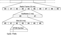
- FIG. 1 is a schematic diagram of an OFDM frame structure according to one embodiment of the present application.
- FIG. 2 is a flowchart of the implementation of master computer software according to one embodiment of the present application.
- FIG. 3 is a schematic diagram of a hardware system architecture according to one embodiment of the present application.
- FIG. 4 is a diagram of the 32-antenna massive MIMO connection according to one embodiment of the present application.
- FIG. 5 is a schematic diagram of data mapping from a transmission block to a layer according to one embodiment of the present application.
- FIG. 6 is a schematic diagram of a frequency domain signal after insertion of a DC subcarrier according to one embodiment of the present application.
- FIG. 7 is a schematic diagram of the insertion of a DC subcarrier into a middle part of a signal according to one embodiment of the present application.
- FIG. 8 is a schematic diagram of an OFDM time domain signal added with a cyclic prefix according to one embodiment of the present application.
- FIG. 9 is a diagram of a time-sharing pilot frame sequence according to one embodiment of the present application.
- FIG. 10 is a diagram of an energy transmission frame sequence according to one embodiment of the present application.
- FIG. 11 is a physical diagram of a system and an antenna array of a base station according to one embodiment of the present application.
- FIG. 12 is a physical diagram of a system of a user end according to one embodiment of the present application.
- FIG. 13 is a base-station-side uplink constellation diagram according to one embodiment of the present application.
- FIG. 14 is a base-station-side channel frequency response diagram according to one embodiment of the present application.
- FIG. 15 is a base-station-side channel impulse response diagram according to one embodiment of the present application.
- FIG. 16 is a user-side downlink received power spectrogram according to one embodiment of the present application.
- FIG. 17 is a user-side downlink constellation diagram and a frequency response diagram according to one embodiment of the present application.
- FIG. 18 is a schematic diagram of an LTE frame generated by a transmitting end according to one embodiment of the present application.
- FIG. 19 is a schematic diagram of a user end receiving a real-time LTE radio frame signal according to one embodiment of the present application.
- FIG. 20 is a schematic diagram of a user end receiving a radio subframe signal according to one embodiment of the present application.
- FIG. 21 is a diagram of the total energy of energy symbols of each frame received by the user end according to one embodiment of the present application.
- FIG. 22 is a schematic diagram of average energy at the user end according to one embodiment of the present application.
- FIG. 23 is a diagram of ratios at the user end according to one embodiment of the present application.
- the massive MIMO wireless energy transmission method based on dynamic frame transmission mainly comprises the following steps: designing a time-sharing pilot frame to control each antenna to transmit a pilot signal to a user end in a time-sharing mode; designing a precoding solution; and designing a synchronous capture mode and a dynamic transmission strategy and the like.
- the TDD radio frame structure is taken as an example to illustrate the design of the time-sharing pilot frame, and a software and hardware experimental simulation platform is used to introduce the communication process and the main improvement points. It should be understood that the idea proposed by the present application is also applicable to current commercial devices, such as base stations and terminal UE.
- FIG. 1 is a schematic diagram of a TDD radio frame structure.
- each radio frame may be divided into 10 subframes which may be further subdivided into half-frames, each having 7 OFDM symbols, wherein the subframe time is 1 ms and the half-frame time is 0.5 ms.
- the TDD frame structure includes DwPTS (Downlink Pilot TimeSlot), DwDTS (Downlink Data TimeSlot), UpPTS (Uplink Pilot TimeSlot), UpDTS (Uplink Data TimeSlot) and Sync (synchronization TimeSlot).
- the subcarrier spacing ⁇ f 15 KHz
- the sampling point of each subcarrier is 2048 (without cyclic prefix)
- the time of one sampling point Ts 0.033 microseconds.
- FIG. 2 and FIG. 3 are software and hardware platforms used herein, respectively, wherein the hardware system mainly includes a host module, a bit processor module, an MIMO processor module, a clock module, a data processing module and the like.
- the bit processor module On the downlink (transmission by the base station), the bit processor module is used for coding and modulating data.
- the MIMO processor is used for precoding IQ data (pilot and modulated source data), and RRH (Remote Radio Head) is used for performing baseband modulation on the precoded data, modulating the precoded data into a baseband signal by using an OFDM technology and finally transmitting the baseband signal in an antenna array.
- RRH Remote Radio Head
- the various modules handle similar tasks.
- the base station receives the pilots and then carries out channel estimation, and sends the calculated equalization matrix to the MIMO processor in the downlink, namely, the uplink state information is used, and the precoding modulation based on the channel reciprocity acts on the downlink.
- a massive MIMO communication platform device provided by Texas instruments in the United States is used for building and testing an actual communication environment, a wireless energy transmission process of massive MIMO is implemented on the basis of an LTE protocol stack, and modification and optimization are performed on the LTE protocol stack aiming at wireless energy transmission, including modification of precoding, dynamic adjustment of a time strategy, feedback of downlink channel state information and the like.
- the specific operation is shown in FIG. 2 .
- An experimental platform is equipped with the hardware connection and the software environment, the system building link is verified reliably by using a massive MIMO application example of NI, and the verification is performed from aspects of constellation diagrams, OFDM symbol power, channel impulse response, symbol delay, received subcarrier amplitude, signal delay and the like.
- the related communication algorithm can be implemented by adopting an FPGA, for example, a communication flow on the FPGA Layer is moved to a master computer for calculation, massive MIMO basic communication based on OFDM modulation of an LTE protocol stack is implemented in the master computer, the processes of coding, interleaving, scrambling, modulation, layer mapping, precoding and the like are carried out on a byte stream downloaded from a network layer at a data link layer, after an OFDM symbol is generated, a direct current (DC) subcarrier is inserted, inverse fast Fourier transform (IFFT) is performed and a cyclic prefix (CP) is inserted, then the OFDM symbol is transmitted from an antenna port, and finally a synchronous symbol is designed to replace the original synchronous symbol of the LTE, so that the master computer at a receiving end can synchronize a signal frame more easily.
- DC direct current
- IFFT inverse fast Fourier transform
- CP cyclic prefix
- the LTE protocol is subjected to customized modification aiming at wireless energy transmission, channel reciprocity is not used, downlink time-sharing antenna pilot transmission is used, that is, a base station transmits pilot signals to a user end through time-sharing control of each antenna, the user end acquires downlink channel state information from the antennae of the base station to the user end, wherein the channel state comprises channel information from each antenna of the base station to the user end, the channel state information of a downlink is fed back to the base station, for example, in a network cable mode, the base station calculates a precoding matrix by using a set precoding solution after acquiring the channel state information, data are mapped to an antenna port from a user layer by using the newly-calculated precoding matrix, and then, a signal frame strategy is adjusted according to the energy of wireless electromagnetic signals received by the user end, therefore, the wireless electromagnetic signal energy received at the user end in a certain time is as large as possible, and the
- a multi-antenna base station-single/double-antenna mobile terminal system built according to NI mainly comprises a main chassis, a sub-chassis, a clock synchronization module and a USRP-RIO 2950 unit.
- the main chassis serves as a main data processing module of the base station and a master node for data traffic gathering.
- the main chassis comprises a high-performance bit processor FPGA processing module used for performing CRC check addition, scrambling and descrambling, and QAM modulation and demodulation on IQ signals on a data stream; the high-performance FPGA MIMO processing module is used for pilot addition, channel estimation and precoding algorithm processing; one clock module is used for synchronizing sub-chasses, generating a clock signal of 10 MHz and controlling the triggering of the clock signal.
- Each sub-chassis comprises 8 USRP-RIOs for gathering and distributing data transmitted by the USRP-RIOs.
- the master computer plate (NI PXIe) of the main chassis is equipped with a Window 10 64 bit operating system connected to mutual peripherals (display screen and keyboard & mouse), and the purpose thereof is as follows: as a master computer, setting initialization of system parameters, displaying various parameters and data charts in the running process in real time, running and debugging the LabVIEW program, and finishing the interaction of software and hardware; displaying the current state of the MIMO system for users, processing data with low instantaneity requirements, and comparing whether the result calculated by the FPGA module is correct or not; and writing, debugging and compiling the FPGA program, wherein a bit file compiled by a specified FPGA program can be loaded when the system is initialized.
- a high-performance 10-MHz oven controlled crystal oscillator is built in to generate clock signals and trigger signals of the base station system, and also to implement routing among multiple devices in the same NI PXI chassis.
- a high-performance FPGA chip of Xilinx is adopted, an FPGA module and a CPS sub-chassis are communicated through high-speed PXI Express, and FPGA programming can be implemented on a hardware circuit in a LabVIEW FPGA environment.
- the sub-chassis is mainly used as a center for distributing and gathering USRP-RIO data.
- FIG. 3 schematically shows that the system comprises two sub-chasses, namely CPS 01 and CPS 02 , wherein each sub-chassis is responsible for gathering data received by 8 USRP-RIO units and then transmitting the data to an FPGA module for calculation, and meanwhile, receiving data transmitted by the FPGA and distributing the data to the 8 USRP-RIOs for transmission.
- the clock synchronization module is mainly used for controlling 16 USRPs in the system to carry out clock synchronization and trigger work, and consists of 5 clock distributors and one clock trigger controller which are connected.
- the MIMO platform can control two USRP subsystems at most.
- Each subsystem consists of eight USRP-RIO devices connected to CPS-8910 devices, referred to as CPS 01 and CPS 02 .
- Clock and synchronous signals received by the USRP subsystem are distributed among the eight USRP-RIO devices in the subsystem by CDA-2990 devices.
- the CDA-2990 devices in the system are named OCLK 01 to OCLK 02 .
- FIG. 4 shows a detailed connection diagram of a massive MIMO system, wherein a reference signal (denoted REF), a primary synchronous signal (denoted PPS) and an MXI signal are shown.
- Uplink and downlink payload data are transmitted over a physical shared channel without the need for forward error correction coding to provide uncoded transmission blocks of precise length to a physical layer.
- the transmission data are a randomly-generated sequence, a piece of fixed-length random
- This framework supports transmission of up to 12 spatial layers, i.e., 12 users, and each mobile station can be allocated a subset of these spatial layers for uplink transmission and downlink reception.
- the base station provides 12 data sources, i.e., 12 random data generators. Each data source is uniquely coupled to a mobile station identified by an MS-ID. Each of up to 12 data sources is assigned its own transmission block processing independently of all other data sources.
- the generated transmission block is mapped to a spatial layer as shown in FIG. 5 . It should be noted that a complete transmission block is mapped to a certain layer before a new transmission block is mapped to another layer, i.e., the transmission block is not split between multiple spatial layers.
- radio frequency transceiver structures include an intermediate frequency transmitter (one or more intermediate frequency conversions), a zero intermediate frequency transmitter (zero intermediate frequency conversion), a digital transmitter and the like.
- the transceiver circuit adopted by the USRP-RIO is designed to be a zero intermediate frequency solution, so that a local oscillator leakage is easily caused in an oscillator circuit inside the transceiver, the circuit is called a mixer, an ideal mixer is used for up-converting a baseband signal to a carrier frequency signal, and a signal of the oscillator circuit of the mixer is leaked to an input port or an output port due to some reasons in a real mixer, so that signal distortion at the midpoint of the bandwidth of a transmitted signal is caused.
- the subcarrier signal skips this frequency point, so that it is specified in the LTE protocol that no data symbol is transmitted on this direct current (DC) subcarrier.
- DC direct current
- guard bands are required to be arranged on both sides of the subcarrier, respectively.
- the frequency domain signal after the insertion of a DC subcarrier is shown in FIG. 6 , wherein the length of the frequency domain signal after the insertion of the DC subcarrier extends from 1200 to 2048, with the signal of the length of 424 to 1624 being data of the modulated subcarrier (except for the midpoint at the length of 1024).
- FIG. 7 is an enlargement at the midpoint of FIG. 6 , and it can be seen that the amplitude of the frequency point at the length of 1024 is 0.
- the frequency domain signal of the length of 2048 after the insertion of the DC subcarrier is subjected to inverse Fourier transform, thereby obtaining a time domain signal with the number of sampling points of 2048.
- signals are not all subjected to point-to-point direct transmission in a free space, and when the signals reach an object or a plane, the signals are scattered, so that the signals have a plurality of different paths from a transmitting end to a receiving end according to different geographic environments, resulting in inconsistent arrival times of the signals of the different paths, and in distortion and even destruction due to mutual superposition of the signals.
- ISI inter-symbol interference
- a guard interval like inserting a DC subcarrier, and fill 0 at the guard interval, so that when a multipath signal falls within the guard interval, no interference is caused to the following signals; the other is to insert a cyclic signal, and a section of the same signal is copied at the tail part or the head part of the OFDM time domain signal and inserted into the head part or the tail part, thereby realizing the cyclic signal of the OFDM.
- the first method is not to transmit any signal in a time interval between two adjacent OFDM symbols, and although this method can reduce inter-symbol interference, it still causes inter-carrier interference (ICI) between different subcarriers in an OFDM symbol, thereby destroying the independence between subcarriers.
- ICI inter-carrier interference
- T sym T sub +T cp
- the data scrambling is carried out, and the scrambling has the functions of reducing interference on other wireless communication terminals, further discretizing the coded data stream in order to disorder the coded data stream, performing spread spectrum in some communication technologies, and encrypting the data to a certain extent to prevent the information leakage caused by eavesdropping.
- the scrambled signal has randomization in both the time domain and the frequency domain.
- a pseudo-random PN sequence is adopted, and the transmitted transmission block is scrambled with the pseudo-random sequence on the basis of each OFDM symbol to provide security against eavesdropping.
- channel estimation is calculated based on channel reciprocity.
- the uplink signal and the downlink signal are transmitted in a time division multiplexing mode, and because there is a sufficiently long channel coherence time between these two signals, the uplink and downlink channels can be assumed to be the same, with the characteristic of perfect alignment of the transmitting and receiving radios, so that the downlink precoding matrix is calculated using the channel state estimated from the uplink pilot.
- the method based on channel reciprocity is a compromise solution made for reducing overhead brought by downlink channel estimation and ensuring communication rate.
- the channel state needs to be estimated by sending downlink pilots, and the channel state acquired at the user end is fed back to the base station in a network cable manner.
- the base station can acquire a complete downlink channel, and thus a downlink channel state can be obtained accurately.
- the time-sharing pilot strategy is adopted in the present application, and in an LTE radio subframe, 14 OFDM symbols are included, there are 13 OFDM symbols after the removal of synchronous symbols, but one OFDM symbol is needed for transmitting pilots by one antenna of the base station, so that one subframe is not enough. Therefore, in one embodiment, a time-sharing pilot frame is defined, and as shown in FIG. 9 , N bs represents the number of antennae at the base station, and N f1 represents the number of energy symbols.
- the time-sharing pilot frame includes three subframes of LTE radio, collectively including 42 OFDM symbols, and can be used for time-sharing pilot transmission of 32 antennae at the base station. All signal frames described below refer to signal frames newly defined, not the LTE radio subframes.
- the time-sharing pilot frame defines the 0 th OFDM symbol as a synchronous frame, and then the 1 st OFDM symbol to the 32 nd OFDM symbol are used for time-sharing pilot transmission of 32 antennae; the 33 rd OFDM symbol is empty, and a blank gap is inserted for distinguishing the transmission pilot and the transmission energy; the 34 th OFDM symbol to the 41 st OFDM symbol are used for energy transmission, and in order not to destroy the orthogonality between the OFDM symbols, the contents of the OFDM symbols with the transmitted energy are generated using PN pseudo random sequence random data.
- the number of radio frames included in the time-sharing pilot frame, and the symbol position and the like used for energy transmission may be defined according to actual needs, for example, the number of antennae at the base station and energy transmission efficiency.
- the present application is not limited thereto.
- the number of antennae at the base station is set as N bs
- the number of antennae at the user end is set as N ue
- the number of subcarriers of OFDM symbols is set as N sub .
- a user end receives time-sharing pilot signals of N bs antennae of a base station, so that the user end performs channel estimation on the N bs pilot signals to obtain a three-dimensional channel state matrix of N bs *N ue ⁇ N sub .
- the data volume increases along with the increase of the number of the antennae of the base station and the user end, if uplink transmission is used, a large amount of delay is caused, and under the condition that the uplink transmission is not suitable for being used, channel information can be fed back to the base station through a network cable.
- the base station needs to perform beamforming calculation through the channel state matrix fed back by the user end, and the calculated precoding solution may adopt an algorithm for maximizing the energy based on singular value decomposition (SVD) proposed in the existing literature.
- SMD singular value decomposition
- the channel states are a matrix of N bs *N ue .
- Singular value decomposition is performed on each H; to obtain a right singular matrix V j , a first column of each V j is taken to obtain a column vector ⁇ right arrow over (v j ) ⁇ with a dimension of N bs , the column vectors ⁇ right arrow over (v j ) ⁇ corresponding to all subcarriers are combined to obtain a precoding matrix W with a dimension of N bs *N sub , and then the precoding matrix W is applied by the base station to a signal to be transmitted to implement a precoding process.
- the conventional synchronization method for synchronous frames is a maximum likelihood algorithm, and the calculation of a large number of synchronous signals by adopting the master computer is very time-consuming, so that the synchronous symbol of the LTE radio frame is redesigned, and the purpose of the design is to enable the mater computer to execute symbol synchronization with a low-complexity calculation amount.
- the original synchronous symbol in the radio frame is designed, and a direct current square wave is used in the design, so that the receiving end can accurately detect the frame starting point, and then the master computer program can more accurately find the frame starting point in the receiving end by designing a sliding window algorithm.
- the design of the sliding window algorithm is set forth below.
- continuously-received signals are stored in a buffer area, wherein the number of sampling points of the signals stored in the buffer area at most may be N t .
- N s a size of a sampling point of a direct current synchronous signal
- S a size of a sliding window
- the sliding window slides from the tail part to the head part of the buffer area, and the purpose of doing so is to process a relatively new data frame first, and then relatively new channel state information can be further obtained.
- the average value V k of signal amplitude values within the window is calculated, wherein 0 ⁇ k ⁇ N t ⁇ N s , and k is an initial position of the sliding window in the buffer area.
- the calculation formula of the average amplitude value V k of the sampling points within the sliding window is expressed as follows:
- the average amplitude value V k can only measure the average amplitude value of the sampling points within the window, the average amplitude value V k is not enough to measure whether the current position of the sliding window is the designed direct current synchronous symbol or not, if the sliding window needs to be determined to be a direct current signal, a floating threshold value ⁇ needs to be set, and when the difference value between the sampling points within the window and the average amplitude value within the window does not exceed the floating threshold value ⁇ , the synchronous symbol can be positioned.
- g k is defined whether the current window is a synchronous symbol or not, and the calculation formula is expressed as follows:
- g k ⁇ 1 , if ⁇ max ⁇ ⁇ ⁇ " ⁇ [LeftBracketingBar]" ⁇ " ⁇ [LeftBracketingBar]” a k + i ⁇ " ⁇ [RightBracketingBar]” - V k ⁇ " ⁇ [RightBracketingBar]” ⁇ ⁇ ⁇ 0 , if ⁇ max ⁇ ⁇ ⁇ " ⁇ [LeftBracketingBar]” ⁇ " ⁇ [LeftBracketingBar]” a k + i ⁇ " ⁇ [RightBracketingBar]” - V k ⁇ " ⁇ [RightBracketingBar]” ⁇ > ⁇ ( 4 ) s . t . i ⁇ 0 , S - 1 ⁇
- the position of the current sliding window is considered the synchronous signal position of one frame, then the starting point k of the sliding window falls on a certain point of the synchronous direct current signal, and one-dimensional reverse search is carried out forward based on this point k, and when
- a threshold value ⁇ of the lowest average amplitude value is set for pruning when the sliding window slides, so as to reduce the operation amount.
- V k ⁇ For a window with an average amplitude value V k ⁇ , no calculation of g k is performed, this is because the position of the current window is not the position of the synchronous signal.
- the position of the sliding window is considered probably the synchronous signal, and then the calculation of g k is carried out.
- ⁇ optimizes the data calculated when the sliding window slides which are unlikely to be a synchronous signal.
- the channel estimation is implemented in the frequency domain, which relies on frequency orthogonal pilots transmitted in the uplink and downlink, respectively, but the uplink pilots are designed to be orthogonal in frequency for each antenna, while the downlink pilots are designed to be orthogonal in frequency for each spatial layer.
- the downlink pilot is transmitted by precoding, similar to the actually transmitted data. Therefore, the acquisition of the channel state information is a huge calculation amount, and the channel state information needs to be calculated in real time through pilots in the communication process, especially for massive MIMO communication, due to the existence of a large number of antenna arrays, the calculation amount of channel state information acquired by the massive MIMO is very large and complicated.
- the widely-used method is least square (LS) estimation, and the formula thereof is as follows:
- Y is a received signal
- n is noise
- X is a pilot signal
- Least square estimation is widely used in channel estimation, and because the operation complexity is low, the corresponding channel coefficient can be estimated by only one multiplication, so that the method is very suitable for massive MIMO channel state calculation.
- the transmission time of time-sharing pilots occupies 76.2% of the time of one signal frame, and the time of energy transmission is only 19% of the time of one signal frame.
- the use of the method can lead most of the time of signal transmission to be used for the transmission of time-sharing pilots instead of energy transmission, so that the occupation time of signal frames in the energy transmission is reduced with the increase of the number of antennae of the massive MIMO, which is worse under the condition that the wireless remote energy transmission efficiency is not high, thus leading the energy utilization rate of a base station to be low and the time of occupying a channel to be long. Therefore, the present application preferably provides an improved signal frame structure to increase the energy transmission efficiency of signal frames.
- the time-sharing pilot frame includes pilot symbols and energy symbols, and the energy transmission frame is composed of only energy symbols.
- the time-sharing pilot frame is named as frame ( 1 ) and the energy transmission frame is named as frame ( 2 ) hereinafter.
- N f N f1
- N f1 the number of energy transmission symbols in the frame ( 1 )
- N f2 the number of energy transmission symbols in the frame ( 2 )
- a size of a sliding frame window is defined as Q, wherein the frame window is used for monitoring a change of an average energy of signal frame energy symbols within the window, and when f ⁇ Q, the average energy P f of signal frame energy symbols within the window at the f th frame is expressed as follows:
- P f,i represents an energy of an i th OFDM energy symbol in the f th frame.
- a change threshold value ⁇ is defined, when an absolute value of a difference value between an energy of each energy symbol of the sliding window at the user end and P f is smaller than ⁇ , a current channel is considered in a slow fading state at the moment, the peripheral interference and noise are relatively stable, the change speed of the channel state is not very high, and then the estimation of the channel state can be considered to be redundant at this time, this is because the estimation of the channel state is used for calculating beamforming to improve energy transmission as much as possible, other than using the channel state to demodulate data in the conventional communication, the former has less strict requirements on the accuracy of channel estimation compared with the latter, so that the transmission of the time-sharing pilots is not useful in this case, and at this time, a dynamic transmission strategy can be used to switch the frame ( 1 ) into the frame ( 2 ).
- the frame ( 2 ) is switched into the frame ( 1 ), and when the energy value of the unit OFDM symbol is stable again, the frame ( 1 ) is switched into the frame ( 2 ).
- the expression of the decision A f+1 (f ⁇ Q) of the f+1 th frame of the above-mentioned dynamic transmission strategy is as follows:
- a f + 1 ⁇ 0 , if ⁇ max ⁇ ⁇ ⁇ " ⁇ [LeftBracketingBar]" p f , i - P f ⁇ " ⁇ [RightBracketingBar]" ⁇ ⁇ ⁇ 1 , if ⁇ max ⁇ ⁇ ⁇ " ⁇ [LeftBracketingBar]” p f , i - P f ⁇ " ⁇ [RightBracketingBar]” ⁇ ⁇ ⁇ ( 7 ) s . t . i ⁇ ⁇ 1 , N f ⁇
- T energy T frame is set as the ratio of the energy transmission time to the signal frame transmission time, wherein T energy represents the total transmission time of energy symbols, and T frame represents the total transmission time of signal frames.
- a base station transmits signals by using 32 directional array antennae, and the base station receives signals by using 32 omnidirectional rod-shaped antennae, and because the array antennae are active directional antennae and circuits inside the antennae are provided with a power amplifier, the base station can only transmit signals but cannot receive signals.
- a user end adopts 2 omnidirectional rod-shaped antennae, and the receiving and transmitting antennae at the user end are integrated. The radio frequency of the base station and the user are both set as 1.2 GHz.
- a physical diagram of a base station-based system is shown in FIG. 11 .
- a physical diagram of a user end-based system is shown in FIG. 12 .
- FIG. 13 is a front panel under the LabVIEW communication program, and it can be seen from the figure that there is a user currently sending uplink data, and the data modulation mode is 16 QAM. Since there is no interference from other users, no matter the uplink constellation diagram is observed from the base station side or the downlink constellation diagram is observed from the user side, the transmission state is relatively consistent with the normal transmission state, and although the constellation points of the constellation diagram are concentrated and the system performance is good, the state is not excellent, this is because the receiving and transmitting antennae at the base station are not integrated, and the estimation based on channel reciprocity is performed on channels from the antennae at the user end to the receiving antennae at the base station. It can be seen from FIG.
- the channel frequency response at the BS side is relatively flat and uniform in power distribution in a bandwidth region of 20 M, which can also be seen from the frequency impulse response of FIG. 15 . Since the transmitting and receiving antennae at the base station are not integrated and the positions of the transmitting and receiving antennae are far apart, under the limitation of the system hardware, the massive MIMO application framework cannot perform channel state estimation of wireless energy communication in a channel reciprocity-based mode.
- the bandwidth of the OFDM subcarrier transmitted from the base station is 20 MHz
- the constellation diagram of FIG. 17 reflects that the massive MIMO multi-antenna array exerts superiority, so that constellation points are very concentrated and the error rate is low, and meanwhile, a frequency response curve under 20 M bandwidth also falls within a good range.
- the constellation points of the user end are better than those of the base station, this is because the transmitting and receiving antennae at the user end are integrated, the problem of inaccurate channel estimation of the base station does not exist.
- the carrier frequency is set to 1.2 GHz
- the base station adopts 32 directional array antennae
- the user end is equipped with 2 antennae.
- FIG. 18 shows a radio subframe time domain signal generated at a transmitting end, which has direct current synchronous frames, pilots and energy signals designed in the present application.
- FIG. 19 is a signal amplitude diagram of a buffer area after signal sampling by a user end, wherein the buffer area has only one complete LTE subframe symbol, this is because the signals are continuously acquired, and the master computer can only process a certain number of sampling points at a time, and the signal sampling rate is set to be relatively moderate in order to ensure the signal processing speed.
- FIG. 20 shows a time domain signal diagram of a radio subframe captured from the buffer area after the user end adopts a new synchronous signal algorithm, and it can be seen from the figure that the algorithm can accurately and quickly find the starting point of a radio frame from the buffer area.
- direct current synchronous signals, downlink pilot signals and energy signals can be seen in the figure.
- the user end can obtain 14 OFDM symbols in one subframe by removing the cyclic prefix, performing FFT transform and removing DC subcarriers, and then obtain channel state information by performing channel estimation on the pilots.
- the experiment is performed on a massive MIMO platform of NI, wherein the number Nis of antennae at the base station is 32 active directional array antennae, and the number N ue of antennae at the user end is 2 omnidirectional rod-shaped antennae.
- the communication carrier frequency of the base station and the user end is set to be 1.2 GHz when the maximum gain of the active array antennae is 21.71 dB, so that beam forming can be better carried out, and the signal energy radiated to the receiving end is more concentrated.
- the height of array antennae at the base station is 1.6 meters, the height of antennae at the user end is 0.4 meters, the horizontal distance between two terminal antennae is 15 centimeters, and the positions of the base station and the user end are fixed in the communication process.
- FIG. 21 , FIG. 22 and FIG. 23 are diagrams of three experimental results of transmitting 600 signal frames when no moving object exists in the test environment, wherein the initial 20 frames are the initialization period of the sliding window Q, and therefore the signal frames are time-sharing pilot frames, and after the initialization of 20 frames, since the change of the average energy P f does not exceed the floating threshold value ⁇ , the base station considers that the downlink channel between the current base station and the user end is relatively stable, and then the time-sharing pilot frames are switches into energy transmission frames. In the following hundreds of frames, since no moving object exists in the environment and the environment state is relatively stable, the energy transmission frames are used in the following transmission process and are not switched into the time-sharing pilot frames. As can be seen from FIG.
- the ratio R starts to increase and approaches 97.6%, this is because the ratio of the energy symbols in the signal frames increases after the switching of energy transmission frames.
- the present application builds an experimental software platform, for example, implements the modulation and scrambling of signals by using LabVIEW language on a master computer, implements a channel estimation algorithm and a precoding algorithm, and creatively provides the redesign of synchronous frames and a maximum energy transmission strategy for adaptively adjusting the frame structure.
- the present application may be a system, a method and/or a computer program product.
- the computer program product may include a computer-readable storage medium having computer-readable program instructions loaded thereon for causing a processor to implement various aspects of the present application.
- the computer-readable storage medium may be a tangible device that holds and stores the instructions for use by an instruction execution device.
- the computer-readable storage medium may include, but is not limited to, for example, an electronic storage device, a magnetic storage device, an optical storage device, an electromagnetic storage device, a semiconductor storage device, or any suitable combination of the foregoing.
- the computer-readable storage medium includes: a portable computer disk, a hard disk drive, a random access memory (RAM), a read-only memory (ROM), an erasable programmable read-only memory (EPROM or flash memory), a static random access memory (SRAM), a portable compact disc read-only memory (CD-ROM), a digital versatile disc (DVD), a memory stick, a floppy disk, a mechanical coding device such as punch card or in-groove raised structure having instructions stored thereon, and any suitable combination of the foregoing.
- RAM random access memory
- ROM read-only memory
- EPROM or flash memory erasable programmable read-only memory
- SRAM static random access memory
- CD-ROM compact disc read-only memory
- DVD digital versatile disc
- memory stick a floppy disk
- mechanical coding device such as punch card or in-groove raised structure having instructions stored thereon
- the computer-readable storage medium as used herein is not to be interpreted as a transitory signal per se, such as a radio wave or other freely propagating electromagnetic wave, an electromagnetic wave propagating through a waveguide or other transmission medium (e.g., optical pulses through a fiber optic cable), or an electrical signal transmitted through an electrical wire.
Landscapes
- Engineering & Computer Science (AREA)
- Computer Networks & Wireless Communication (AREA)
- Signal Processing (AREA)
- Mobile Radio Communication Systems (AREA)
Abstract
Description
-
- controlling, by a base station, each antenna to transmit a pilot signal to a user end in a time-sharing mode by using a set time-sharing pilot frame;
- acquiring, by the user end, downlink channel state information from the antennae of the base station to the user end and feeding the downlink channel state information back to the base station; and
- calculating, by the base station, a precoding matrix based on the downlink channel state information, mapping data from a user layer to an antenna port by using the newly calculated precoding matrix, and performing beam forming calculation with maximization of an energy signal of the user end as a goal.
-
- data is generated by using uniform white noise each time, the length being dynamically adjusted according to a modulation mode, the length of the sequence is added to the head part of the data, and finally the CRC code of the sequence is added to the tail part of the data. The length calculation formula is expressed as follows:
-
- wherein Lt is the length of a transmission block, Nsub is the number of subcarriers, and Bmod is the number of bits of modulation symbols.
| TABLE 1 |
| Byte number corresponding to different modulation modes |
| Modulation mode | Size of symbol (bit) | Length (byte) |
| |
2 | 300 |
| 16- |
4 | 600 |
| 64- |
6 | 900 |
| 256- |
8 | 1200 |
c(n)=(x 1(n+N c)+(x 2(n+N c))mod 2x 1(n+31)=(x 1(n+3)+x 1)mod 2x 2(n+31)=(x 2(n+3)+x 2(n+2)+x 2(n+1)+x 2(n))mod 2 (2)
-
- wherein Nc=1600, 0≤n≤MPN−1.
is set as the ratio of the energy transmission time to the signal frame transmission time, wherein Tenergy represents the total transmission time of energy symbols, and Tframe represents the total transmission time of signal frames.
Claims (10)
Applications Claiming Priority (1)
| Application Number | Priority Date | Filing Date | Title |
|---|---|---|---|
| PCT/CN2021/123801 WO2023060507A1 (en) | 2021-10-14 | 2021-10-14 | Dynamic frame transmission-based large-scale mimo wireless energy transmission method |
Related Parent Applications (1)
| Application Number | Title | Priority Date | Filing Date |
|---|---|---|---|
| PCT/CN2021/123801 Continuation WO2023060507A1 (en) | 2021-10-14 | 2021-10-14 | Dynamic frame transmission-based large-scale mimo wireless energy transmission method |
Publications (2)
| Publication Number | Publication Date |
|---|---|
| US20230119957A1 US20230119957A1 (en) | 2023-04-20 |
| US11824604B2 true US11824604B2 (en) | 2023-11-21 |
Family
ID=85981987
Family Applications (1)
| Application Number | Title | Priority Date | Filing Date |
|---|---|---|---|
| US17/955,325 Active US11824604B2 (en) | 2021-10-14 | 2022-09-28 | Massive MIMO wireless energy transmission method based on dynamic frame transmission |
Country Status (2)
| Country | Link |
|---|---|
| US (1) | US11824604B2 (en) |
| WO (1) | WO2023060507A1 (en) |
Families Citing this family (3)
| Publication number | Priority date | Publication date | Assignee | Title |
|---|---|---|---|---|
| CN118784037A (en) * | 2024-06-20 | 2024-10-15 | 电子科技大学长三角研究院(湖州) | Beamforming method and system for digital energy cooperative transmission system |
| CN120034901B (en) * | 2024-06-24 | 2025-08-26 | 中国科学院国家空间科学中心 | A method and system for merging and splicing satellite multiple downlink transmission frame data |
| CN120498937B (en) * | 2025-06-18 | 2026-04-03 | 中南民族大学 | Hybrid precoding method and equipment for OFDM time-modulated antenna array systems |
Citations (9)
| Publication number | Priority date | Publication date | Assignee | Title |
|---|---|---|---|---|
| US20120120907A1 (en) * | 2009-07-24 | 2012-05-17 | Panasonic Corporation | Wireless communication device and wireless communication method |
| CN104600873A (en) | 2015-01-20 | 2015-05-06 | 东南大学 | Large-scale antenna array oriented wireless energy information transmission network power control method |
| CN104601297A (en) | 2015-01-30 | 2015-05-06 | 北京邮电大学 | Coordinative wireless energy transmission method and system |
| US20150229133A1 (en) | 2012-09-19 | 2015-08-13 | Duke University | Subscription based miso and mimo wireless energy transfer |
| US20160294461A1 (en) * | 2015-03-30 | 2016-10-06 | Sony Corporation | Systems, methods and computer program products for optimizing a wireless channel between a user equipment and a base station |
| US20170104561A1 (en) * | 2014-03-28 | 2017-04-13 | Sony Corporation | Pilot time slot allocation for a mimo system |
| US20190074876A1 (en) * | 2016-05-05 | 2019-03-07 | Ntt Docomo, Inc. | Mechanism and procedure of base station selection based on uplink pilot and distributed user-proximity detection |
| CN110414289A (en) | 2019-08-01 | 2019-11-05 | 杭州立宸科技有限公司 | Low-power consumption Internet of Things wireless power MIMO beam form-endowing method |
| US20200014433A1 (en) * | 2017-03-17 | 2020-01-09 | Sony Mobile Communications Inc. | Operating a terminal device and a base station in a wireless mimo system |
-
2021
- 2021-10-14 WO PCT/CN2021/123801 patent/WO2023060507A1/en not_active Ceased
-
2022
- 2022-09-28 US US17/955,325 patent/US11824604B2/en active Active
Patent Citations (9)
| Publication number | Priority date | Publication date | Assignee | Title |
|---|---|---|---|---|
| US20120120907A1 (en) * | 2009-07-24 | 2012-05-17 | Panasonic Corporation | Wireless communication device and wireless communication method |
| US20150229133A1 (en) | 2012-09-19 | 2015-08-13 | Duke University | Subscription based miso and mimo wireless energy transfer |
| US20170104561A1 (en) * | 2014-03-28 | 2017-04-13 | Sony Corporation | Pilot time slot allocation for a mimo system |
| CN104600873A (en) | 2015-01-20 | 2015-05-06 | 东南大学 | Large-scale antenna array oriented wireless energy information transmission network power control method |
| CN104601297A (en) | 2015-01-30 | 2015-05-06 | 北京邮电大学 | Coordinative wireless energy transmission method and system |
| US20160294461A1 (en) * | 2015-03-30 | 2016-10-06 | Sony Corporation | Systems, methods and computer program products for optimizing a wireless channel between a user equipment and a base station |
| US20190074876A1 (en) * | 2016-05-05 | 2019-03-07 | Ntt Docomo, Inc. | Mechanism and procedure of base station selection based on uplink pilot and distributed user-proximity detection |
| US20200014433A1 (en) * | 2017-03-17 | 2020-01-09 | Sony Mobile Communications Inc. | Operating a terminal device and a base station in a wireless mimo system |
| CN110414289A (en) | 2019-08-01 | 2019-11-05 | 杭州立宸科技有限公司 | Low-power consumption Internet of Things wireless power MIMO beam form-endowing method |
Also Published As
| Publication number | Publication date |
|---|---|
| WO2023060507A1 (en) | 2023-04-20 |
| US20230119957A1 (en) | 2023-04-20 |
Similar Documents
| Publication | Publication Date | Title |
|---|---|---|
| US11824604B2 (en) | Massive MIMO wireless energy transmission method based on dynamic frame transmission | |
| US10554264B2 (en) | System and method for reducing pilot signal contamination using orthogonal pilot signals | |
| US9819526B2 (en) | Apparatus and methods for low PAPR transmission in MIMO systems | |
| KR102427434B1 (en) | Apparatus and method for transmitting/receiving signal in wireless communication system supporting distributed antenna system | |
| US11503614B2 (en) | Downlink data transmission method and device | |
| WO2020063038A1 (en) | Timing advance in new radio | |
| Farhang et al. | Massive MIMO and waveform design for 5th generation wireless communication systems | |
| CN114124180B (en) | Large-scale MIMO wireless energy transmission method and device based on dynamic frame transmission and storage medium | |
| US9960887B2 (en) | Method and apparatus of signal transmission and reception in a filter bank multiple carrier system | |
| EP3526909A1 (en) | Method and apparatus for covariance matrix feedback in advanced wireless communication systems | |
| Muhammad et al. | Optimizing age of information in RIS-empowered uplink cooperative NOMA networks | |
| US12231281B2 (en) | Frame structure indication method, frame structure updating method, and related device | |
| US12010054B2 (en) | DMRS transmission | |
| CN105744516B (en) | A kind of communication system and method promoting safety of physical layer performance using energy station | |
| US20250167959A1 (en) | System and method for reference signal configuration, transmission and reception | |
| KR20080041385A (en) | Beam forming apparatus and method in communication system, and system accordingly | |
| Cao et al. | Implementation of a cell-free RAN system with distributed cooperative transceivers under ORAN architecture | |
| Cao et al. | From oran to cell-free ran: Architecture, performance analysis, testbeds and trials | |
| US11316570B2 (en) | Apparatuses and methods for non-linear precoding | |
| Haci et al. | A novel interference cancellation technique for non-orthogonal multiple access (NOMA) | |
| Tateishi et al. | 5G experimental trial achieving over 20 Gbps using advanced multi-antenna solutions | |
| CN101499988B (en) | Wideband wireless mobile communication method, system and equipment | |
| Aljalai et al. | Improving the energy efficiency of dft-s-ofdm in uplink massive mimo with barker codes | |
| Tuovinen et al. | RF system requirement analysis and simulation methods towards 5G radios using massive MIMO | |
| Khelil et al. | MRC SC-FDMA scheme performance evaluation based on measurements at 30 GHz for 5G communications |
Legal Events
| Date | Code | Title | Description |
|---|---|---|---|
| AS | Assignment |
Owner name: SHENZHEN UNIVERSITY, CHINA Free format text: ASSIGNMENT OF ASSIGNORS INTEREST;ASSIGNORS:CHE, YUELING;LI, YISHEN;LI, LIANGZHU;AND OTHERS;REEL/FRAME:061247/0836 Effective date: 20220919 |
|
| FEPP | Fee payment procedure |
Free format text: ENTITY STATUS SET TO UNDISCOUNTED (ORIGINAL EVENT CODE: BIG.); ENTITY STATUS OF PATENT OWNER: SMALL ENTITY |
|
| FEPP | Fee payment procedure |
Free format text: ENTITY STATUS SET TO SMALL (ORIGINAL EVENT CODE: SMAL); ENTITY STATUS OF PATENT OWNER: SMALL ENTITY |
|
| STPP | Information on status: patent application and granting procedure in general |
Free format text: DOCKETED NEW CASE - READY FOR EXAMINATION |
|
| STPP | Information on status: patent application and granting procedure in general |
Free format text: EX PARTE QUAYLE ACTION MAILED |
|
| STPP | Information on status: patent application and granting procedure in general |
Free format text: RESPONSE TO EX PARTE QUAYLE ACTION ENTERED AND FORWARDED TO EXAMINER |
|
| STPP | Information on status: patent application and granting procedure in general |
Free format text: NOTICE OF ALLOWANCE MAILED -- APPLICATION RECEIVED IN OFFICE OF PUBLICATIONS |
|
| STPP | Information on status: patent application and granting procedure in general |
Free format text: PUBLICATIONS -- ISSUE FEE PAYMENT RECEIVED |
|
| STPP | Information on status: patent application and granting procedure in general |
Free format text: PUBLICATIONS -- ISSUE FEE PAYMENT VERIFIED |
|
| STCF | Information on status: patent grant |
Free format text: PATENTED CASE |