US1181663A - Safety door-holder. - Google Patents
Safety door-holder. Download PDFInfo
- Publication number
- US1181663A US1181663A US74984313A US1913749843A US1181663A US 1181663 A US1181663 A US 1181663A US 74984313 A US74984313 A US 74984313A US 1913749843 A US1913749843 A US 1913749843A US 1181663 A US1181663 A US 1181663A
- Authority
- US
- United States
- Prior art keywords
- door
- holder
- spring
- washer
- safety door
- Prior art date
- Legal status (The legal status is an assumption and is not a legal conclusion. Google has not performed a legal analysis and makes no representation as to the accuracy of the status listed.)
- Expired - Lifetime
Links
Images

Classifications
-
- A—HUMAN NECESSITIES
- A62—LIFE-SAVING; FIRE-FIGHTING
- A62C—FIRE-FIGHTING
- A62C2/00—Fire prevention or containment
- A62C2/06—Physical fire-barriers
- A62C2/12—Hinged dampers
-
- E—FIXED CONSTRUCTIONS
- E05—LOCKS; KEYS; WINDOW OR DOOR FITTINGS; SAFES
- E05F—DEVICES FOR MOVING WINGS INTO OPEN OR CLOSED POSITION; CHECKS FOR WINGS; WING FITTINGS NOT OTHERWISE PROVIDED FOR, CONCERNED WITH THE FUNCTIONING OF THE WING
- E05F3/00—Closers or openers with braking devices, e.g. checks; Construction of pneumatic or liquid braking devices
- E05F3/22—Additional arrangements for closers, e.g. for holding the wing in opened or other position
- E05F3/221—Mechanical power-locks, e.g. for holding the wing open or for free-moving zones
- E05F3/222—Mechanical power-locks, e.g. for holding the wing open or for free-moving zones electrically operated
-
- Y—GENERAL TAGGING OF NEW TECHNOLOGICAL DEVELOPMENTS; GENERAL TAGGING OF CROSS-SECTIONAL TECHNOLOGIES SPANNING OVER SEVERAL SECTIONS OF THE IPC; TECHNICAL SUBJECTS COVERED BY FORMER USPC CROSS-REFERENCE ART COLLECTIONS [XRACs] AND DIGESTS
- Y10—TECHNICAL SUBJECTS COVERED BY FORMER USPC
- Y10S—TECHNICAL SUBJECTS COVERED BY FORMER USPC CROSS-REFERENCE ART COLLECTIONS [XRACs] AND DIGESTS
- Y10S16/00—Miscellaneous hardware, e.g. bushing, carpet fastener, caster, door closer, panel hanger, attachable or adjunct handle, hinge, window sash balance
- Y10S16/17—Checks and closers, holding means
Definitions
- QR itncmeo anvawtoz W. K. HENRY.
- My invention relates to a safety door holder, the same being of particular utility when employed in connection with suitable door closer mechanism.
- the object of the invention is to provide a holder construction whereby the door with which said holder is associated may be held open at the desired angle against the closing influence of the closer mechanism, but which is also so constructed that in the event of a fire in the neighborhood of said door, the holder will be automatically released so that the door closer may close the door to confine the fire to the apartment protected by the door.
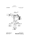
- Figure 1 is a side elevation of my invention as applied directly to a door closer.
- Fig. 2 15 a plan view thereof.
- Fig. 3 is a view of certain parts, as shown in Fig. 1, said view being partly in section.
- Fig. 4 is a detail view.
- Fig. 5 is a plan view, on a relatively enlarged scale, of another detail.
- Fig. 6 is a cross section of the parts shown in Fig. 5.
- Fig. 7 is a section of one of the parts shown in Fig. 6.
- Fig. 8 is a section of another of the parts shown in Fig. 6.
- FIG. 1 represents a case or housing of what is conventionally known as a door closer, the particular construction of which is immaterial.
- the parts 1 and 3 may be suitably connected with the door and door casing respectively in such a way as to cause the door to close automatically.
- One simple and common form of such mechanism comprises an abutment 4 carried by a ring 5 adjustable on the head of the casing 1 so as to position the abutment 4 at any desired angle.
- the detent 6 is a yielding detent carried by the arm 3 and provided with a beveled nose so that it may be pressed back by a sufficiently forceful contact with the abutment 4.
- the detent 6 is held projected by a spring 7 usually mounted on the top side of the arm 3, the spring being put under suitable tension in any desired manner; for example, by means of a screw 8.
- I employ means associated with the holder mechanism in the form of a readily fusible metal, which operates in a sense as a coupling or link at some convenient place between the various operative parts of the holder mechanism so that in the event of fire in the neighborhood of the door, the fusible material will soften and thus free the holder and allow the closer to close the door with which it is associated.
- I make said coupler in the form of a washer 9, this washer 9 being formed of metal which melts at a relatively low temperature.
- This washer I locate between the under side of the head 8 of the screw 8 and the upper side of the spring 7 so that by turning down on the screw 8, the spring 7 may be put under the desired tension against the detent 6.
- a safety door stop for swinging doors comprising, a spindle, a mounting therefor, an arm carried by said spindle and projectranged between said headed portion and said spring, whereby tension on the spring will be relieved in the event of extreme heat.
- a safety door stop for swinging doors comprising, a spindle,-a mounting therefor, an arm carried by said spindle and projecting laterally therefrom, an abutment carried by one of said parts, a yielding detent carried by another part and arranged to cooperate with said abutment, a spring operating against said detent, and means to put said spring under tension, said means hav ing a shank and a headed portion and a fusible member around said shank, and arranged between said headed portion and said spring, whereby tension on the spring will be relieved in the event of extreme heat, and a reinforcing wall around said fusible member, said reinforcement being of rela tively non-fusible material.
Description
W. K. HENRY.
SAFETY DOOR HOLDER.
APPLICATION FILED FEB. 21. 1913.
1 1 8 1 ,663 Patented May 2, 1916.
2 SHFETS-SHEET I.
QR itncmeo: anvawtoz W. K. HENRY.
SAFETY DOOR HOLDER.
APPLICAHON HLED 1 58.21. |9\3. 1,181,663, Patented May 2,1916.
2 SHEETS- SHEET 2.
70 ;@9 9 mum 1111033031 1 V W N UNITED STATES PATENT OFFICE.
WILLIAM K. HENRY, OF NEW BRITAIN, CONNECTICUT, ASSIGNOR TO THE AMERICAN HARDWARE CORPORATION, OF NEW BRITAIN, CONNECTICUT, A CORPORATION OF CONNECTICUT.
SAFETY DOOR-HOLDER Specification of Letters Patent.
Application filed February 21, 1913. Serial No. 749,843.
T 0 all whom it may concern:
Be it known that I, WILLIAM K. HENRY, a citizen of the United States, residing at New Britain, Hartford county, State of Connecticut, have invented certain new and useful Improvements in Safety Door-Holders, of which the following is a full clear, and exact description.
My invention relates to a safety door holder, the same being of particular utility when employed in connection with suitable door closer mechanism.
The object of the invention is to provide a holder construction whereby the door with which said holder is associated may be held open at the desired angle against the closing influence of the closer mechanism, but which is also so constructed that in the event of a fire in the neighborhood of said door, the holder will be automatically released so that the door closer may close the door to confine the fire to the apartment protected by the door.
In the accompanying drawings: Figure 1 is a side elevation of my invention as applied directly to a door closer. Fig. 2 15 a plan view thereof. Fig. 3 is a view of certain parts, as shown in Fig. 1, said view being partly in section. Fig. 4 is a detail view. Fig. 5 is a plan view, on a relatively enlarged scale, of another detail. Fig. 6 is a cross section of the parts shown in Fig. 5. Fig. 7 is a section of one of the parts shown in Fig. 6. Fig. 8 is a section of another of the parts shown in Fig. 6.
It should be understood that I have shown herein and shall describe my invention in only a preferred form, but that various modifications may be readily made without departure from the spirit and scope thereof.
1 represents a case or housing of what is conventionally known as a door closer, the particular construction of which is immaterial.
2 is a spring-controlled spindle which carries a closer arm 3. The parts 1 and 3 may be suitably connected with the door and door casing respectively in such a way as to cause the door to close automatically. In many instances it is desirable to provide a holder whereby the door may be held ajar against the closing tendency of the closer mechanism. For example, in communicating doors between oflices or apartments, it is frequently desirable to have the doors held open.
To that'end spring holder devices have been employed in the past in connection with door closing mechanism so that when the door has been opened beyond a certain predetermined point, the holder device engages and holds the door at that angle against the closing tendency of the closer mechanism until manual pressure is applied sufficient to overcome the resistance of the stop mechanism. One simple and common form of such mechanism comprises an abutment 4 carried by a ring 5 adjustable on the head of the casing 1 so as to position the abutment 4 at any desired angle.
6 is a yielding detent carried by the arm 3 and provided with a beveled nose so that it may be pressed back by a sufficiently forceful contact with the abutment 4. The detent 6 is held projected by a spring 7 usually mounted on the top side of the arm 3, the spring being put under suitable tension in any desired manner; for example, by means of a screw 8.
In the present instance, I employ means associated with the holder mechanism in the form of a readily fusible metal, which operates in a sense as a coupling or link at some convenient place between the various operative parts of the holder mechanism so that in the event of fire in the neighborhood of the door, the fusible material will soften and thus free the holder and allow the closer to close the door with which it is associated. In one simple embodiment of this idea, I make said coupler in the form of a washer 9, this washer 9 being formed of metal which melts at a relatively low temperature. This washer I locate between the under side of the head 8 of the screw 8 and the upper side of the spring 7 so that by turning down on the screw 8, the spring 7 may be put under the desired tension against the detent 6. It is obvious that so long as the washer 9 retains its shape, this tension in the spring 7 will be continued. If, however, the washer becomes heated above a certain temperature, it will at once soften, whereupon the strain of the spring 7 on the detent 6 being removed, the closer arm 3 will be swung in a direction to close the door.
From the foregoing it will readily be seen that a very substantial factor of safety is added to buildings by the employment of devices of this character, for, as will be ap- Patented May 2, 1916.
parent, if a fire should occur in one apartment of a building, the door or doors of the apartment in WhlCh the fire occurs would close automatically and very quickly, thereby at least hindering, if. not entirely preventing, the spread of the fire to an adjacent apartment.
When I employ a washer 9, I prefer to employ a cupped washer 10 providing a confimng wall of relatively non-fusible material about the edge and base thereof and in which the fusible washer 9 may be seated, as shown in Fig. 6. This construction affords this advantage: In the event a fire occurs and the washer 9 melts so as to release the tension on the spring 7, the sprin 7 will rise only slightly in the vicinity o the screw 8 so that the head 8 of the screw will sink only partially into the fused metal in the cupped washer 10, displacing only a ortion thereof. As soon as this cools off, it will be found that suflicient fusible metal is retained in the cupped Washer to permit the screw 8 to be again turned down so as to restore the tension on the spring 7 In actual practice the coupler shown in the drawings may work two or three times without requiring the replacement of a new fusible washer.
What I claim is:
1. A safety door stop for swinging doors comprising, a spindle, a mounting therefor, an arm carried by said spindle and projectranged between said headed portion and said spring, whereby tension on the spring will be relieved in the event of extreme heat.
2. A safety door stop for swinging doors comprising, a spindle,-a mounting therefor, an arm carried by said spindle and projecting laterally therefrom, an abutment carried by one of said parts, a yielding detent carried by another part and arranged to cooperate with said abutment, a spring operating against said detent, and means to put said spring under tension, said means hav ing a shank and a headed portion and a fusible member around said shank, and arranged between said headed portion and said spring, whereby tension on the spring will be relieved in the event of extreme heat, and a reinforcing wall around said fusible member, said reinforcement being of rela tively non-fusible material.
WILLIAM K. HENRY.
Witnesses:
N. G. CURTIS, WILLIAM V. COLLINS.
Priority Applications (1)
| Application Number | Priority Date | Filing Date | Title |
|---|---|---|---|
| US74984313A US1181663A (en) | 1913-02-21 | 1913-02-21 | Safety door-holder. |
Applications Claiming Priority (1)
| Application Number | Priority Date | Filing Date | Title |
|---|---|---|---|
| US74984313A US1181663A (en) | 1913-02-21 | 1913-02-21 | Safety door-holder. |
Publications (1)
| Publication Number | Publication Date |
|---|---|
| US1181663A true US1181663A (en) | 1916-05-02 |
Family
ID=3249638
Family Applications (1)
| Application Number | Title | Priority Date | Filing Date |
|---|---|---|---|
| US74984313A Expired - Lifetime US1181663A (en) | 1913-02-21 | 1913-02-21 | Safety door-holder. |
Country Status (1)
| Country | Link |
|---|---|
| US (1) | US1181663A (en) |
-
1913
- 1913-02-21 US US74984313A patent/US1181663A/en not_active Expired - Lifetime
Similar Documents
| Publication | Publication Date | Title |
|---|---|---|
| US3261631A (en) | Magnetic latching mechanism | |
| US1181663A (en) | Safety door-holder. | |
| US1288532A (en) | Automatic locking device for fire-windows. | |
| US1648662A (en) | Safety cut-out for gas mains and the like | |
| US1257301A (en) | Mechanism for automatically closing fire-doors. | |
| US3147830A (en) | Releasable hold open device | |
| US2057702A (en) | Accelerated gravity shut-off valve | |
| US1242749A (en) | Door-latch. | |
| US1133453A (en) | Door-check. | |
| US1993224A (en) | Door controlling device | |
| US897449A (en) | Sash-pivot. | |
| US1254877A (en) | Door check and closer. | |
| US2923026A (en) | Door closer mechanism | |
| US1065508A (en) | Burglar-alarm. | |
| US1094961A (en) | Controlling means for swinging closures. | |
| US784637A (en) | Door-securer and alarm combined. | |
| US653295A (en) | Door-check. | |
| US625867A (en) | Door-locking burglar-alarm | |
| US183203A (en) | Improvement in burglar-alarms | |
| US2177770A (en) | Photographic camera | |
| US629613A (en) | Sash-lock. | |
| US1461294A (en) | Burglar alarm | |
| US2390467A (en) | Lock | |
| US700652A (en) | Burglar-alarm. | |
| US1278465A (en) | Safety door-holder. |