US11812927B2 - Motion translation and interface devices, systems, and methods for endoscope valves - Google Patents

Motion translation and interface devices, systems, and methods for endoscope valves Download PDF

Info

Publication number
US11812927B2
US11812927B2 US17/208,772 US202117208772A US11812927B2 US 11812927 B2 US11812927 B2 US 11812927B2 US 202117208772 A US202117208772 A US 202117208772A US 11812927 B2 US11812927 B2 US 11812927B2
Authority
US
United States
Prior art keywords
valve
channel
state
air input
atmospheric
Prior art date
Legal status (The legal status is an assumption and is not a legal conclusion. Google has not performed a legal analysis and makes no representation as to the accuracy of the status listed.)
Active, expires
Application number
US17/208,772
Other versions
US20210298571A1 (en
Inventor
Shaun D. Comee
Paula R. Limberg
Laura E. Richards
Rossana Zotti
Current Assignee (The listed assignees may be inaccurate. Google has not performed a legal analysis and makes no representation or warranty as to the accuracy of the list.)
Boston Scientific Scimed Inc
Original Assignee
Boston Scientific Scimed Inc
Priority date (The priority date is an assumption and is not a legal conclusion. Google has not performed a legal analysis and makes no representation as to the accuracy of the date listed.)
Filing date
Publication date
Application filed by Boston Scientific Scimed Inc filed Critical Boston Scientific Scimed Inc
Priority to US17/208,772 priority Critical patent/US11812927B2/en
Assigned to BOSTON SCIENTIFIC SCIMED, INC. reassignment BOSTON SCIENTIFIC SCIMED, INC. ASSIGNMENT OF ASSIGNORS INTEREST (SEE DOCUMENT FOR DETAILS). Assignors: ZOTTI, Rossana, RICHARDS, LAURA E., LIMBERG, Paula R., COMEE, SHAUN D.
Publication of US20210298571A1 publication Critical patent/US20210298571A1/en
Priority to US18/482,226 priority patent/US20240032774A1/en
Application granted granted Critical
Publication of US11812927B2 publication Critical patent/US11812927B2/en
Active legal-status Critical Current
Adjusted expiration legal-status Critical

Links

Images

Classifications

    • AHUMAN NECESSITIES
    • A61MEDICAL OR VETERINARY SCIENCE; HYGIENE
    • A61BDIAGNOSIS; SURGERY; IDENTIFICATION
    • A61B1/00Instruments for performing medical examinations of the interior of cavities or tubes of the body by visual or photographical inspection, e.g. endoscopes; Illuminating arrangements therefor
    • A61B1/00064Constructional details of the endoscope body
    • A61B1/00066Proximal part of endoscope body, e.g. handles
    • A61B1/00068Valve switch arrangements
    • AHUMAN NECESSITIES
    • A61MEDICAL OR VETERINARY SCIENCE; HYGIENE
    • A61BDIAGNOSIS; SURGERY; IDENTIFICATION
    • A61B1/00Instruments for performing medical examinations of the interior of cavities or tubes of the body by visual or photographical inspection, e.g. endoscopes; Illuminating arrangements therefor
    • A61B1/012Instruments for performing medical examinations of the interior of cavities or tubes of the body by visual or photographical inspection, e.g. endoscopes; Illuminating arrangements therefor characterised by internal passages or accessories therefor
    • A61B1/015Control of fluid supply or evacuation
    • AHUMAN NECESSITIES
    • A61MEDICAL OR VETERINARY SCIENCE; HYGIENE
    • A61BDIAGNOSIS; SURGERY; IDENTIFICATION
    • A61B1/00Instruments for performing medical examinations of the interior of cavities or tubes of the body by visual or photographical inspection, e.g. endoscopes; Illuminating arrangements therefor
    • A61B1/12Instruments for performing medical examinations of the interior of cavities or tubes of the body by visual or photographical inspection, e.g. endoscopes; Illuminating arrangements therefor with cooling or rinsing arrangements
    • FMECHANICAL ENGINEERING; LIGHTING; HEATING; WEAPONS; BLASTING
    • F16ENGINEERING ELEMENTS AND UNITS; GENERAL MEASURES FOR PRODUCING AND MAINTAINING EFFECTIVE FUNCTIONING OF MACHINES OR INSTALLATIONS; THERMAL INSULATION IN GENERAL
    • F16KVALVES; TAPS; COCKS; ACTUATING-FLOATS; DEVICES FOR VENTING OR AERATING
    • F16K21/00Fluid-delivery valves, e.g. self-closing valves
    • F16K21/04Self-closing valves, i.e. closing automatically after operation
    • F16K21/18Self-closing valves, i.e. closing automatically after operation closed when a rising liquid reaches a predetermined level
    • F16K21/20Self-closing valves, i.e. closing automatically after operation closed when a rising liquid reaches a predetermined level by means making use of air-suction through an opening closed by the rising liquid
    • AHUMAN NECESSITIES
    • A61MEDICAL OR VETERINARY SCIENCE; HYGIENE
    • A61BDIAGNOSIS; SURGERY; IDENTIFICATION
    • A61B1/00Instruments for performing medical examinations of the interior of cavities or tubes of the body by visual or photographical inspection, e.g. endoscopes; Illuminating arrangements therefor
    • A61B1/00064Constructional details of the endoscope body
    • A61B1/00071Insertion part of the endoscope body
    • A61B1/0008Insertion part of the endoscope body characterised by distal tip features
    • A61B1/00082Balloons
    • AHUMAN NECESSITIES
    • A61MEDICAL OR VETERINARY SCIENCE; HYGIENE
    • A61BDIAGNOSIS; SURGERY; IDENTIFICATION
    • A61B1/00Instruments for performing medical examinations of the interior of cavities or tubes of the body by visual or photographical inspection, e.g. endoscopes; Illuminating arrangements therefor
    • A61B1/012Instruments for performing medical examinations of the interior of cavities or tubes of the body by visual or photographical inspection, e.g. endoscopes; Illuminating arrangements therefor characterised by internal passages or accessories therefor
    • A61B1/018Instruments for performing medical examinations of the interior of cavities or tubes of the body by visual or photographical inspection, e.g. endoscopes; Illuminating arrangements therefor characterised by internal passages or accessories therefor for receiving instruments

Definitions

  • the present disclosure relates generally to the field of medical devices.
  • the present disclosure relates to devices, systems, and methods to control flow through a valve well for an endoscope.
  • An endoscopy procedure is used in medicine to access the interior of a body for diagnostic and/or therapeutic procedures.
  • the endoscopy procedure uses an endoscope to examine or manipulate the interior of a hollow organ or cavity of the body.
  • endoscopes are inserted directly into the organ.
  • an endoscope includes one or more channels for the flow of one or more fluids therethrough.
  • suction, air, and water may flow through an endoscope.
  • a valve assembly may be configured and used in various fashion to control the flow of the one or more fluids through the endoscope.
  • control of fluids may also be used to inflate and deflate a balloon at the end of an endoscope.
  • the present disclosure relates to a medical device comprising a valve set and a valve interface mechanism.
  • the valve set may include a valve set including a primary control valve, an air input valve, and an atmospheric valve, the primary control valve may be configured to control flow between a water input channel, a water output channel, and a balloon channel of a valve well, the air input valve may be configured to control flow through an air input channel of the valve well, and the atmospheric valve may be configured to control flow through an atmospheric channel.
  • the valve interface mechanism may include a set of one or more biasing members and a user interface mechanism.
  • the user interface mechanism may comprise a toggle coupled to a cam, the toggle may be operable between a first state, a second state, a third state, and a fourth state, the first state may comprise the valve set configured to place the air input channel in fluid communication with the atmospheric channel, the second state may comprise the valve set configured to place the air input channel in fluid communication with the air output channel, the third state may comprise the valve set configured to place the water input channel in fluid communication with the water output channel, and the fourth state may comprise the valve set configured to place the water input channel in fluid communication with the balloon channel.
  • the air input valve permits flow through the air input channel and the atmospheric valve permits flow through the atmospheric channel.
  • the second state the air input valve permits flow through the air input channel and the atmospheric valve blocks flow through the atmospheric valve.
  • the primary control valve permits flow from the water input channel to the water output channel and the air input valve blocks flow through the air input channel.
  • the primary control valve permits flow from the water input channel to the balloon channel and the air input valve blocks flow through the air input channel.
  • the cam may translate motion of the toggle into linear motion of the primary control valve.
  • the cam may comprise a plurality of steps, wherein each of the plurality of steps causes a different amount of linear motion of the primary control valve.
  • the plurality of steps may comprise a first step corresponding to the second state, a second step corresponding to the third state, and a third step corresponding to the fourth state.
  • the cam may comprise a plurality of steps, wherein each of the plurality of steps are configured to seal the atmospheric channel.
  • the toggle is configured to receive input to operate the user interface to one or more of the first state, the second state, the third state, and the fourth state.
  • the set of one or more biasing members may comprise a first biasing member to bias the primary control valve toward a top of the valve well.
  • the set of one or more biasing members may comprise a second biasing member to couple the primary control valve to the air input valve.
  • the set of one or more biasing members may comprise a biasing member to bias the air input valve against the air input channel in the third and fourth states.
  • the biasing member may prevent the air input valve from blocking the air input channel in the first and second states.
  • the present disclosure relates to a medical device comprising a valve set and a user interface mechanism.
  • the valve set may include a primary control valve, an air input valve, and an atmospheric valve, the primary control valve may be configured to control flow between a water input channel, a water output channel, and a balloon channel of a valve well, the air input valve may be configured to control flow through an air input channel of the valve well, and the atmospheric valve may be configured to control flow through an atmospheric channel.
  • the valve interface mechanism may include a set of one or more biasing members and a user interface mechanism, the user interface mechanism may comprise an interface member and a slot cam, the interface member may be operable between a first state, a second state, a third state, and a fourth state, the first state may comprise the valve set configured to place the air input channel in fluid communication with the atmospheric channel, the second state may comprise the valve set configured to place the air input channel in fluid communication with the air output channel, the third state may comprise the valve set configured to place the water input channel in fluid communication with the water output channel, and the fourth state may comprise the valve set configured to place the water input channel in fluid communication with the balloon channel.
  • the air input valve permits flow through the air input channel and atmospheric valve permits flow through the atmospheric channel.
  • the air input valve permits flow through the air input channel and the atmospheric valve blocks flow through the atmospheric valve.
  • the primary control valve permits flow from the water input channel to the water output channel and the air input valve blocks flow through the air input channel.
  • the primary control valve permits flow from the water input channel to the balloon channel and the air input valve blocks flow through the air input channel.
  • the slot cam may translate rotational motion of the interface member into linear motion of the primary control valve.
  • the linkage may couple the cam pin to the primary control valve.
  • the cam pin may follow the slot cam to translate rotational motion of the interface member into linear motion of the primary control valve. Transition from one or more of the first state to the second state, the second state to the third state, and the third state to the fourth state may produce tactile feedback via the interface member.
  • the tactile feedback may be created by different angles of different portions of the slot cam.
  • the present disclosure relates to a method.
  • the method may include placing an air input channel of a valve well in fluid communication with an atmospheric channel based on operation of a valve interface mechanism to a first state, the valve set comprising a primary control valve, an air input valve, and an atmospheric valve, wherein the primary control valve comprises the air input valve.
  • the method may include placing the air input channel in fluid communication with an air output channel of the valve well based on operation of the valve interface mechanism to a second state.
  • the method may include placing the water input channel in fluid communication with a water output channel of the valve well based on operation of the valve interface mechanism to a third state.
  • the method may include placing the water input channel in fluid communication with the balloon channel of the valve well based on operation of the valve interface mechanism to a fourth state.
  • the method may include rotating an interface member in a first direction to operate the user interface mechanism to the second state and rotating the interface member in a second direction to operate the user interface mechanism to the third state and/or fourth state.
  • the method may include rotating the interface member adjust one or more valves in an air/water valve set via a cam.
  • the method may include operating one or more of a lever, a rocker switch, and an interface member to adjust between one or more of the first state, the second state, the third state, and the fourth state.
  • the present disclosure relates to a method.
  • the method may include configuring a valve set to place an air input channel of a valve well in fluid communication with an atmospheric channel based on operation of an interface member to a first state.
  • the method may include configuring the valve set to place the air input channel in fluid communication with an air output channel of the valve well based on operation of the interface member to a second state.
  • the method may include configuring the valve set to place the water input channel in fluid communication with a water output channel of the valve well based on operation of the interface member to a third state.
  • the method may include configuring the valve set to place the water input channel in fluid communication with the balloon channel of the valve well based on operation of the interface member to a fourth state.
  • the method may comprise rotating the interface member in a first direction to operate the interface member to the third state and rotating the interface member in a second direction to operate the interface member to the fourth state.
  • the method may include translating the rotation of the interface member into a linear motion of one or more valves in the valve set via a cam.
  • the method may include translating the rotation of the interface member into a linear motion of one or more valves in the valve set via a slot cam.
  • FIG. 1 includes a block diagram of an exemplary suction valve assembly, according to one or more embodiments described herein.
  • FIG. 2 includes a block diagram of an exemplary air/water (AW) valve assembly, according to one or more embodiments described herein.
  • AW air/water
  • FIGS. 3 A- 3 D illustrate various aspects of an exemplary suction valve well, according to one or more embodiments described herein.
  • FIGS. 4 A- 4 E illustrate various aspects of an exemplary AW valve well, according to one or more embodiments described herein.
  • FIG. 5 illustrates an exemplary suction valve set, according to one or more embodiments described herein.
  • FIGS. 6 A- 8 C illustrate various aspects of exemplary valves in suction valve sets, according to one or more embodiments described herein.
  • FIG. 9 illustrates an exemplary AW valve set, according to one or more embodiments described herein.
  • FIGS. 10 A- 12 C illustrate various aspects of exemplary valves in AW valve sets, according to one or more embodiments described herein.
  • FIG. 13 illustrates an exemplary AW valve assembly, according to one or more embodiments described herein.
  • FIGS. 14 A- 14 E illustrate various aspects of an exemplary AW valve assembly, according to one or more embodiments described herein.
  • Various embodiments are generally directed to devices, systems, and methods for controlling the flow of fluids in endoscopic systems, such as endoscopic ultrasound (EUS) enabled endoscopes. Some embodiments are particularly directed to valve sets and/or valve interface mechanisms for controlling air, water, and/or suction flow through a valve well for an endoscopic system. Several embodiments are directed to user interface mechanisms and techniques for enabling an operator to interact with and control endoscope valves. Many embodiments are directed to mechanisms and techniques for translating interface input motion into valve control motions. In one or more embodiments, the valve sets and/or valve interface mechanisms may be disposable. These and other embodiments are described and claimed.
  • Some challenges when controlling the flow of fluids through endoscopes include unreliable valves prone to failure. For example, many valves and valve interface mechanisms are fragile and likely to leak. These issues can be compounded when the components are designed, constructed, and/or assembled economically to facilitate disposal after a single use. Alternatively, these issues can be compounded when reusable components are worn down from multiple use/cleaning cycles. Adding further complexity, user interface mechanisms may be confusing to operate and require a steep learning curve. For instance, delicate and nonintuitive movements may be required to accurately control fluid flows. Further, little or no feedback may be provided to indicate how a set of valves is arranged.
  • an operator may not be able to easily discern via a user interface mechanism whether the set of valves is arranged to provide suction to a working channel or provide suction to a balloon channel.
  • Various embodiments described herein include one or more components of a valve assembly, such as valves and/or valve interface mechanisms, that provide reliable and intuitive control of fluid flow through endoscopes.
  • the components may provide reliable operation while providing sufficient value to be disposable (e.g., single-use).
  • the components may provide accurate and intuitive interfaces to improve operator experience.
  • embodiments may utilize one or more of up-and-down, forward-and-back, side-to-side, and rotational interfaces to provide ergonomic and intuitive control of fluid flows through endoscopes.
  • Some such embodiments may include one or more interface members, such as push/pull switches, bellows, rotational switches, knobs, buttons, and toggle switches.
  • one or more of the components may provide/enable tactile feedback.
  • one or more components of the valve interface mechanism may provide tactile or haptic feedback to indicate how a set of valves is arranged (e.g., arranged to permit/block flows between various channels).
  • the force to operate a user interface mechanism may vary to indicate transitions between valve states.
  • tactile feedback may be produced as a result of different components of a valve assembly coming into contact, such as due to received input.
  • one or more of the components may be designed to simplify manufacturability.
  • the location of one or more biasing members may simplify component assembly.
  • components/techniques described here may improve operator experience, decrease learning curves, improve reliability, and/or decrease manufacturing complexity via realization of more efficient and valuable devices, systems, and methods for controlling the flow of fluids in endoscopic systems.
  • one or more of the advantageous features may result in several technical effects and advantages over conventional technology, including increased capabilities and improved adaptability.
  • embodiments of the present disclosure may be described with specific reference to specific medical devices and systems (e.g., an endoscope), it should be appreciated that such medical devices and systems may be used in a variety of medical procedures which require navigating one or more accessory tools through ductal, luminal, or vascular anatomies, including, for example, interventional radiology procedures, balloon angioplasty procedures, thrombolysis procedures, angiography procedures, Endoscopic Retrograde Cholangio-Pancreatography (ERCP) procedures, and the like.
  • the disclosed medical devices and systems may be inserted via different access points and approaches, e.g., percutaneously, endoscopically, laparoscopically or some combination thereof.
  • distal refers to the end farthest away from the medical professional/operator when introducing a device into a patient
  • proximal refers to the end closest to the medical professional when introducing a device into a patient
  • FIGS. 1 and 2 illustrate block diagrams of exemplary valve assemblies in environments 100 , 200 , according to one or more embodiments described herein.
  • Environment 100 may include a suction valve assembly 102 with a suction valve well 104 , a suction valve set 118 , and a valve interface mechanism 126 .
  • Environment 200 may include an air/water (AW) valve assembly 202 with an AW valve well 204 , an AW valve set 218 , and a valve interface mechanism 226 .
  • AW air/water
  • various components of suction valve assembly 102 and/or AW valve assembly 202 may interoperate to provide reliable and intuitive control of fluid flow through endoscopic systems.
  • one or more components of valve sets 118 , 218 and valve interface mechanisms 126 , 226 may provide reliable and intuitive control of fluid flow through suction valve well 104 or AW valve well 204 .
  • components of a valve assembly may be classified as, belong to, include, implement, and/or interoperate with one or more of a valve well, a valve set, and a valve interface mechanism.
  • a valve interface mechanism may include one or more portions of a valve. Embodiments are not limited in this context.
  • the suction valve well 104 may include suction channel 106 , working channel 108 , balloon channel 114 , and atmospheric channel 116 ; the suction valve set 118 may include working channel valve 120 , balloon valve 122 , and atmospheric valve 124 ; and the valve interface mechanism 126 may include biasing member set 128 and user interface mechanism 130 .
  • the channels of the suction well 104 may be connected to other components in an endoscopic system, such as via tubing or piping.
  • the suction channel 106 may be connected to a suction source, the working channel 108 may be connected to a working channel of an endoscopic device (e.g., endoscope or component disposed therethrough), the balloon channel 114 may be connected to a balloon of an endoscopic device.
  • suction valve set 118 and valve interface mechanism 126 may control the flow of suction (e.g., induced by negative pressure relative to atmospheric pressure) through suction valve well 104 .
  • the flow of suction may be controlled to the suction channel 106 from one of the working channel 108 , the balloon channel 114 , and the atmospheric channel 116 .
  • the AW valve well 204 may include air input channel 206 , water input channel 208 , air output channel 210 , water output channel 212 , balloon channel 214 , and atmospheric channel 216 ; the AW valve set 218 may include primary control valve 220 , air input valve 222 , and atmospheric valve 224 ; and the valve interface mechanism 226 may include biasing member set 228 and user interface mechanism 230 .
  • the channels of the AW well 204 may be connected to other components in an endoscopic system, such as via tubing or piping.
  • the air input channel 206 may be connected to a pressurized air source
  • the water input channel 208 may be connected to a water source
  • the air output channel 210 may be connected to an air channel of an endoscopic device (e.g., endoscope or component disposed therethrough)
  • the water output channel 212 may be connected to a water channel of an endoscopic device
  • the balloon channel 214 may be connected to a balloon of an endoscopic device.
  • AW valve set 218 and valve interface mechanism 226 may control the flow of air and water through AW valve well 204 .
  • the flow of air may be controlled from air input channel 206 to one of the air output channel 210 , the atmospheric channel 216 , or blocked, and/or the flow of water may be controlled from water input channel 208 to one of water output channel 212 , the balloon channel 214 , or blocked.
  • suction valve assembly 102 and/or AW valve assembly 202 may be used in conjunction with an endoscopic system, such as an EUS system.
  • reference to a balloon may refer to a balloon in the EUS system that can be inflated/deflated to provide medium to facilitate transmission of sound waves and capturing of ultrasound images.
  • valve interface mechanism 126 may receive input to control the flow through suction valve well 104 to deflate the balloon by arranging the suction valve set 118 to place the suction channel 106 in fluid communication with the balloon channel 114 .
  • valve interface mechanism 226 may receive input to control the flow of water through AW valve well to inflate the balloon by arranging the AW valve set 218 to place the water input channel 208 in fluid communication with balloon channel 214 .
  • one or more of the components of the valve assembly for AW and/or suction may be implemented in configurations that do not require or include a balloon, such as video capable scope with ultrasound functionality.
  • each channel in a valve well may refer to a flow path comprising an input/output of a fluid from/to a corresponding entity.
  • suction channel 106 may refer to a flow path comprising an input from a suction source.
  • an atmospheric channel may refer to a flow path comprising an output to the atmosphere.
  • the primary control valve 220 may place the water input channel 208 in fluid communication with the water output channel 212 , and in a second position, the primary control valve 220 may place the water input channel 208 in fluid communication with the balloon channel 214 .
  • the valve interface mechanisms may include one or more components to enable control over the arrangement of valves in a valve set.
  • biasing member sets may include one or more, torsional springs, lever springs, coil spring, baffles, dampers, clips, and the like that provide a force to bias one or more components in a specific direction or position.
  • the biasing member set 228 may cause air to flow out the atmospheric channel when no input is being received.
  • the biasing member set 128 may provide differing resistance to operation of the user interface mechanism 130 between different states, such as to provide tactile indications of the state.
  • each of the user interface mechanisms 130 , 230 may include one or more of an interface, an interface member, a user interface, a housing, a linkage, a knob, a lever, a rocker switch, a push/pull switch, a knob, a button, a diaphragm switch, a toggle switch, and the like.
  • an interface, an interface member, and/or a user interface may be the same or similar.
  • user interface mechanisms may include one or more components to receive input and/or implement valve arrangements.
  • user interface mechanism 130 may include a user interface comprising a lever and one or more linkages to translate motion of the lever into appropriate motion of one or more valves to achieve a desired flow.
  • user interface mechanisms may include one or more biasing members and/or biasing members may include one or more user interface mechanisms.
  • one or more components described herein in the context of a suction valve assembly may be utilized in or adapted for use in an AW valve assembly, and vice versa, without departing from the scope of this disclosure.
  • a rotational user interface mechanism described with respect to a suction valve interface mechanism may be utilized in or adapted for use in an AW valve interface mechanism.
  • FIGS. 3 A- 4 E illustrate various aspects of exemplary valve well block diagrams of exemplary valve assemblies in environments 300 A-D, 400 A-E, according to one or more embodiments described herein. In some embodiments, one or more components of FIGS. 3 A- 4 E may be the same or similar to one or more other components described herein.
  • Environments 300 A-D illustrate a suction valve well 304 comprising a suction channel 306 , a working channel 308 , a balloon channel 314 and an atmospheric channel 315 .
  • Environments 400 A-E illustrate an AW valve well 404 with an air input channel 406 , a water input channel 408 , an air output channel 210 , a water output channel 212 , a balloon channel 214 , and an atmospheric channel 216 .
  • fluid may flow through the valve wells based on the arrangement of one or more valves as positioned by one or more valve interface mechanisms. Embodiments are not limited in this context.
  • environment 300 A illustrates various components of suction valve well 304 .
  • the suction valve well 304 may include a top 345 and a bottom 335 .
  • the suction channel 306 , working channel 308 , and balloon channel 314 may comprise respective entrances/exits towards the bottom 355 while the atmospheric channel 316 may comprise an entrance towards the top 345 .
  • the balloon channel 314 includes a necking portion 334
  • the working channel 308 includes a well radial hole 336
  • the atmospheric channel 316 includes a lip 332 .
  • the necking portion 334 may enable a valve to prevent fluid flow through the balloon channel 314 , such as by blocking the necking portion 334 .
  • the well radial hole 336 may enable the working channel 308 to be placed in fluid communication with the suction channel 306 .
  • the lip 332 may enable one or more suction valve sets and/or valve interface mechanisms to couple to the suction valve well 304 .
  • valves and/or valve interface mechanisms may be inserted through atmospheric channel 316 for assembly of a suction valve assembly. It will be appreciated that the orientation and/or arrangement of one or more of the channels and/or flows may be modified in various embodiments without departing from the scope of this disclosure.
  • environment 300 B illustrates a flow 338 - 1 through the suction valve well 304 in an atmospheric suction state 305 - 1 .
  • flow 338 - 1 may enter via the atmospheric channel 316 and exit through the suction channel 306 .
  • suction channel 306 may be an input in the handle of a medical scope that is connected to a vacuum system, such as for a hospital, home, and/or mobile device.
  • fluid communication with the atmosphere may be provided through a passage/channel in, or created by, one or more components (e.g., a valve inserted into the atmospheric channel 316 ). Further, one or more components may be used to seal portions of the atmospheric channel 316 to facilitate blocking of fluid communication with the atmosphere by an atmospheric valve.
  • one or more components e.g., a valve inserted into the atmospheric channel 316 .
  • one or more components may be used to seal portions of the atmospheric channel 316 to facilitate blocking of fluid communication with the atmosphere by an atmospheric valve.
  • environment 300 C illustrates a flow 338 - 2 through the suction valve well 304 in a working channel suction state 305 - 2 .
  • flow 338 - 2 may enter via the working channel 308 , pass through the well radial hole 336 , and exit through the suction channel 306 .
  • flow may be blocked through the balloon channel 314 at the necking portion 334 and flow may be blocked through the atmospheric channel 316 .
  • environment 300 D illustrates a flow 338 - 3 through the suction valve well 304 in a balloon channel suction state 305 - 3 .
  • flow 338 - 3 may enter via the balloon channel 314 and exit through the suction channel 306 .
  • flow may be blocked through the working channel 308 at the well radial hole 336 and may be blocked through the atmospheric channel 316 .
  • environment 400 A illustrates various components of AW valve well 404 .
  • the AW valve well 404 may include a top 445 and a bottom 435 and/or an air portion 425 and a water portion 435 .
  • the air output channel 410 , air input channel 412 , and atmospheric channel 416 may be in the air portion 425 .
  • the atmospheric channel 416 may comprise a horizontally-oriented exit towards the top 345 and lip 432
  • the air input channel 412 may comprise a horizontally-oriented entrance towards the top 345
  • the air output channel 410 may comprise a vertically-oriented exit towards the top.
  • the water input channel 408 , water output channel 412 , and balloon channel 414 may be in the water portion 435 .
  • the balloon channel 414 may comprise a vertically-oriented exit proximate the middle
  • the water input channel 408 may comprise a vertically-oriented entrance toward the bottom 455
  • the water output channel 412 may comprise a vertically-oriented exit toward the bottom 455 .
  • the lip 432 may enable one or more suction valve sets and/or valve interface mechanisms to couple to the AW valve well 404 .
  • the AW valve well 404 may change diameters one or more times.
  • the diameter changes in conjunction with vertical displacement of a valve may enable flow around the valve and through a channel.
  • the AW valve well may have a first diameter comprising the entrance/exits of the air input/atmospheric channels 412 , 416 , a second diameter comprising the exit of the air output channel 410 , a third diameter comprising the entrance/exit of the water input/balloon channels 408 , 414 , and a fourth diameter comprising the exit of the water output channel 412 .
  • the orientation, size, and/or arrangement of one or more of the channels and/or flows may be modified in various embodiments without departing from the scope of this disclosure.
  • environment 400 B illustrates a flow 438 - 1 through the AW valve well 404 in an air escape state 405 - 1 .
  • flow 438 - 1 may enter via air input channel 406 and exit through the atmospheric channel 416 . Further, in some embodiments, flow may be blocked through one or more of balloon channel 414 , water input channel 408 , and water output channel 412 .
  • environment 400 C illustrates a flow 438 - 2 through the AW valve well 404 in an air delivery state 405 - 2 .
  • flow 438 - 2 may enter via the air input channel 406 and exit through the air output channel 410 . Further, in various embodiments, flow may be blocked through one or more of atmospheric channel 416 , balloon channel 414 , water input channel 408 , and water output channel 412 .
  • environment 400 D illustrates a flow 438 - 3 through the AW valve well 404 in a water delivery state 405 - 3 .
  • flow 438 - 3 may enter via water input channel 408 and exit through the water output channel 412 .
  • flow may be blocked through one or more of the balloon channel 414 , air output channel 410 , air input channel 406 , and atmospheric channel 416 .
  • blocking flow at the air input channel 406 may cause pressure to build in a water source feeding the water input channel 408 .
  • pressure in the water source may cause fluid to flow from the water source to water input channel 408 .
  • environment 400 E illustrates a flow 438 - 4 through the AW valve well 404 in a balloon fill state 405 - 4 .
  • flow 438 - 4 may enter via the water input channel 408 and exit through the balloon channel 414 . Further, in many embodiments, flow may be blocked through one or more of the water output channel 412 , air output channel 410 , air input channel 406 , and atmospheric channel 413 .
  • FIGS. 5 - 12 C illustrate various aspects of exemplary valve sets in environments 500 , 600 A, 600 B, 700 A, 700 B, 800 A-C, 900 , 1000 A, 1000 B, 1100 A, 1100 B, 1200 A-C, according to one or more embodiments described herein.
  • one or more components of FIGS. 5 - 12 C may be the same or similar to one or more other components described herein.
  • Environments 500 - 800 C illustrate various aspects of a suction valve set 518 in conjunction with one or more components of suction valve well 304 .
  • Environments 900 - 1200 C illustrate various aspects of an AW valve set 918 in conjunction with one or more components of AW valve well 404 .
  • fluid may flow through the valve wells based on the arrangement of one or more valves as positioned by one or more valve interface mechanisms.
  • one or more valves described herein may include a plurality of components configured to control fluid through a valve well. Embodiments are not limited in this context.
  • Suction valve set 518 may include working channel valve 520 , balloon valve 522 , and atmospheric valve 524 .
  • the working channel valve 520 may include a working channel valve radial hole 540 that enables fluid to flow into the working channel valve 520 out of the bottom of the working channel valve 520 .
  • the working channel valve 520 may be inserted into the working channel of suction valve well 304 to control flow therethrough.
  • the balloon valve 522 may be inserted into balloon channel 314 of suction valve well 304 to control flow therethrough.
  • the atmospheric valve 524 may be inserted into the atmospheric channel of suction valve well 304 to control flow therethrough.
  • one or more valves in suction valve set 518 may be integrated with one or more portions of a housing and/or valve interface mechanism corresponding to suction valve well 304 .
  • the atmospheric valve 524 may be configured to control fluid communication with the atmosphere from the interior of the suction valve well 304 .
  • the atmospheric valve 524 may include a hole in a housing.
  • the atmospheric valve 524 may be operated by covering and/or uncovering the hole, such as with a finger or other mechanism.
  • the positioning and/or configuration of the valves in suction valve set 518 may be controlled by one or more components of a corresponding valve interface mechanism.
  • depressing a valve interface mechanism to a first stop may simultaneously shut off atmospheric suction via a seal on the underside of a cap and open working channel suction by pushing down the center of the working channel valve 520 to align the working channel valve radial hole 540 and the well radial hole.
  • environment 600 A illustrates a balloon valve open state 615 - 1 .
  • the balloon valve 522 may allow flow through the balloon channel 314 by permitting flow through the necking portion 334 of balloon channel 314 .
  • environment 600 B illustrates a balloon valve sealed state 615 - 2 .
  • the balloon valve 522 may prevent flow through balloon channel 314 by blocking flow through the necking portion 334 of balloon channel 314 .
  • the default state of the balloon valve 522 may be the balloon valve sealed state 615 - 2 and the balloon valve 522 may be depressed toward the bottom 355 and below the necking portion 334 to transition into the balloon valve open state 615 - 1 .
  • environment 700 A illustrates an atmospheric valve open state 715 - 1 .
  • the atmospheric valve 524 may allow flow through the atmospheric channel 316 of suction valve well 304 .
  • environment 700 B illustrates an atmospheric valve sealed state 715 - 2 .
  • the atmospheric valve 524 may prevent flow through atmospheric channel 316 .
  • fluid communication with the atmosphere may be provided through a passage/channel in, or created by, one or more components. Further, one or more components may be used to seal portions of the atmospheric channel 316 to facilitate control of fluid communication with the atmosphere by atmospheric valve 524 .
  • atmospheric valve 524 may include a plurality of components configured to control fluid communication with the atmosphere.
  • environment 800 A illustrates a working channel valve first sealed state 815 - 1 .
  • the working channel valve 520 may prevent flow through well radial hole 336 by misaligning the working channel valve radial hole 540 with the well radial hole 336 , such as with working channel valve 520 being positioned such that working channel valve radial hole 540 is above well radial hole 336 .
  • environment 800 B illustrates a working channel valve open state 815 - 2 .
  • the working channel valve radial hole 540 and the well radial hole 336 may be aligned to permit suction flow through working channel 308 .
  • the flow may enter through the bottom of the working channel valve 520 and exit through the well radial hole 336 .
  • environment 800 C illustrates a working channel valve second sealed state 815 - 3 .
  • the working channel valve 520 may prevent flow through well radial hole 336 by misaligning the working channel valve radial hole 540 with the well radial hole 336 , such as with working channel valve 520 being positioned such that working channel radial hole 440 is below well radial hole 336 .
  • AW valve set 918 may include primary control valve 920 , air input valve 922 , and atmospheric valve 924 .
  • the primary control valve 920 may be inserted into the AW valve well 404 to control, at least in part, the flow through one or more channels of the AW valve well 404 .
  • the air input valve 922 may be inserted into the air input channel of the AW valve well 404 to control flow therethrough.
  • the atmospheric valve 924 may be inserted into the atmospheric channel of AW valve well 404 to control flow therethrough.
  • one or more valves in AW valve set 918 may be integrated with one or more portions of a housing and/or valve interface mechanism corresponding to AW valve well 404 .
  • the atmospheric valve 924 may be configured to control fluid communication with the atmosphere from the interior of the AW valve well 404 .
  • the atmospheric valve 924 may include a hole in a housing.
  • the atmospheric valve 924 may be operated by covering and/or uncovering the hole, such as with a finger or other mechanism.
  • the positioning and/or configuration of the valves in AW valve set 918 may be controlled by one or more components of a corresponding valve interface mechanism.
  • one or more portions of the atmospheric channel 416 may be included in the primary control valve 920 .
  • the atmospheric channel 416 may comprise one or more passages through at least a portion of the primary control valve 920 .
  • the atmospheric channel 416 may comprise a hole in the top of the primary control valve 920 in fluid communication with a radial hole in the primary control valve 920 proximate the air input channel 406 .
  • covering the hole may direct air flow into the air output channel 410 and down a working channel of an endoscope.
  • environment 1000 A illustrates an atmospheric valve open state.
  • the atmospheric valve 924 may allow flow through the atmospheric channel of AW valve well 404 .
  • environment 1000 B illustrates an atmospheric valve sealed state 1015 - 2 .
  • the atmospheric valve 924 may prevent flow through atmospheric channel of AW valve well 404 .
  • fluid communication with the atmosphere may be provided through a passage/channel in, or created by, one or more components (e.g., primary control valve 920 ). Further, one or more components may be used to seal portions of the atmospheric channel 316 to facilitate control of fluid communication with the atmosphere by atmospheric valve 924 .
  • atmospheric valve 924 may include a plurality of components configured to control fluid communication with the atmosphere.
  • environment 1100 A illustrates an air input valve open state 1115 - 1 .
  • the air input valve 522 may allow flow through the air input channel of AW valve well 404 .
  • environment 1100 B illustrates an air input valve sealed state 1115 - 2 .
  • the air input valve 922 may prevent flow through the air input channel of AW valve well 404 .
  • sealing the air input channel may cause a fluid source (e.g., water reservoir) to be pressurized, thereby enabling/causing fluid to flow into the AW valve well 404 via water input channel 408 .
  • a fluid source e.g., water reservoir
  • environment 1200 A illustrates a primary valve sealed state 1215 - 1 .
  • the primary control valve 920 may prevent flow through one or more of the balloon channel 414 , water input channel 408 , and water output channel 412 .
  • environment 1200 B illustrates a primary valve water output state 1215 - 2 .
  • the primary control valve 920 may be positioned to block flow through balloon channel 414 and permit flow from water input channel 408 to water output channel 412 .
  • primary control valve 920 may utilize changes in diameter in AW valve well 404 to control flow. Referring to FIG.
  • FIG. 12 C illustrates a primary valve balloon fill state 1215 - 3 .
  • the primary control valve 920 may be positioned to block flow through water output channel 412 and permit flow from water input channel 408 to balloon channel 414 .
  • one or more features of primary control valve 920 may operate as valves for multiple channels.
  • one or more features of primary control valve 920 may comprise one or more channels, or one or more portions thereof.
  • primary control valve 920 may comprise atmospheric channel 416 .
  • FIG. 13 illustrates an exemplary AW valve assembly 1302 in environment 1300 , according to one or more embodiments described herein.
  • AW valve assembly 1302 includes an AW valve well 1304 , an AW valve set, and a valve interface mechanism.
  • the AW valve well 1304 includes air input channel 1306 , water input channel 1308 , air output channel 1310 , water output channel 1312 , balloon channel 1314 , and lip 1332 .
  • the AW valve set may include primary control valve 1320 with interior channel 1321 and atmospheric channel 1316 , air input valve 1322 , and atmospheric valve 1324 .
  • the air input valve 1322 and the atmospheric valve 1324 may include, or be included in, one or more portions of the valve interface mechanism.
  • the valve interface mechanism includes biasing members 1328 - 1 , 1328 - 2 , toggle 1350 , cam 1352 with atmospheric valve 1324 , housing 1354 , and linkages 1364 - 1 , 1364 - 2 .
  • toggle 1350 may be moved to control the flow of fluid through AW valve assembly 1302 , such as by switching between an air escape state 1305 - 1 , an air delivery state 1305 - 2 , a water delivery state 1305 - 3 , and a balloon fill state 1305 - 4 .
  • Embodiments are not limited in this context.
  • the linkage 1364 - 1 may be attached to, or included in, primary control valve 1320 .
  • air input valve 1322 may be coupled to linkage 1364 - 1 via biasing member 1328 - 1 .
  • linkage 1364 - 2 may seat in the AW valve well 1304 to enable biasing member 1328 - 2 to push against linkage 1364 - 1 and bias primary control valve 1320 toward the top.
  • primary control valve 1320 may be able to slide up and down through linkage 1364 - 2 .
  • housing 1354 may couple to the AW valve well 1304 via lip 1332 .
  • the housing 1354 may provide a rigid mounting point for one or more components of AW valve assembly 1302 , such as for toggle 1350 and cam 1352 to rotatably couple to.
  • cam 1352 may enable motion of toggle 1350 to be translated into linear motion of primary control valve 1320 .
  • cam 1352 may include a profile with one or more steps, such as to seal atmospheric channel 1316 and/or move primary control valve 1320 toward the bottom.
  • cam 1352 may include three steps or levels with a first step corresponding to the air delivery state 1305 - 2 , a second step corresponding to the water delivery state 1305 - 3 , and a third step corresponding to the balloon fill state 1305 - 4 .
  • articulating toggle 1350 between different positions may cause cam 1352 to contact and/or move primary control valve 1320 to switch between the air escape state 1305 - 1 , the air delivery state 1305 - 2 , the water delivery state 1305 - 3 , and the balloon fill state 1305 - 4 .
  • a spring may be coupled to toggle 1350 to bias the toggle 1350 , and thereby the primary control valve 1320 , into a specific position or state.
  • the cam 1352 may be positioned out of contact with the primary control valve 1320 to enable fluid from air input valve 1322 through the interior channel 1321 and escape to atmosphere through the top of the primary control valve 1320 via atmospheric channel 1316 .
  • biasing member 1328 - 2 may force primary control valve 1320 toward the top of the AW valve assembly 1302 .
  • biasing member 1328 - 1 may ensure that air input valve 1322 is in an open state due to biasing member 1328 - 2 forcing primary control valve 1320 toward the top of the AW valve assembly 1302 .
  • the first step of cam 1352 may be positioned in contact with the primary control valve 1320 such that the first step of the cam 1352 acts as atmospheric valve 1324 and seals atmospheric channel 1316 .
  • fluid may flow from the air input channel 1306 to the air output channel 1310 via interior channel 1321 .
  • biasing member 1328 - 2 may force primary control valve 1320 toward the top of the AW valve assembly 1302 to facilitate sealing between the atmospheric channel 1316 and the first step of the cam 1352 .
  • first step of cam 1352 may only slightly compress biasing member 1328 - 2 and slightly force linkage 1364 - 1 downward such that biasing member 1328 - 1 is still able to ensure that air input valve 1322 is in an open state due to biasing member 1328 - 2 forcing primary control valve 1320 toward the top of the AW valve assembly 1302 .
  • the second step of cam 1352 may be positioned in contact with the primary control valve 1320 such that the second step of the cam 1352 acts as atmospheric valve 1324 and seals atmospheric channel 1316 . Additionally, positioning the second step of cam 1352 in contact with the primary control valve 1320 may force the primary control valve 1320 toward the bottom, causing air input valve 1322 to seal against air input channel 1306 and placing water input channel 1308 in fluid communication with water output channel 1312 . In the water delivery state 1305 - 3 , fluid flow from the air input channel 1306 may be blocked by air input valve 1322 and fluid may flow from the water input channel 1308 to the water output channel 1312 .
  • biasing member 1328 - 2 may force primary control valve 1320 toward the top of the AW valve assembly 1302 to facilitate sealing between the atmospheric channel 1316 and the second step of the cam 1352 . Further, the second step of cam 1352 may compress biasing member 1328 - 2 and force linkage 1364 - 1 downward such that biasing member 1328 - 1 forces air input valve 1322 downward to seal air input channel 1306 .
  • the third step of cam 1352 may be positioned in contact with the primary control valve 1320 such that the third step of the cam 1352 acts as atmospheric valve 1324 and seals atmospheric channel 1316 . Additionally, positioning the third step of cam 1352 in contact with the primary control valve 1320 may force the primary control valve 1320 toward the bottom, causing air input valve 1322 to seal against air input channel 1306 and placing water input channel 1308 in fluid communication with balloon channel 1314 . In the balloon fill state 1305 - 4 , fluid flow from the air input channel 1306 may be blocked by air input valve 1322 and fluid may flow from the water input channel 1308 to the balloon channel 1314 .
  • biasing member 1328 - 2 may force primary control valve 1320 toward the top of the AW valve assembly 1302 to facilitate sealing between the atmospheric channel 1316 and the third step of the cam 1352 . Further, the third step of cam 1352 may compress biasing member 1328 - 2 and force linkage 1364 - 1 downward such that biasing member 1328 - 1 forces air input valve 1322 downward to seal air input channel 1306 .
  • FIGS. 14 A- 14 E illustrate various aspects of an exemplary AW valve assembly 1402 in environments 1400 A-E, according to one or more embodiments described herein.
  • a cross section of one or more portions of AW valve assembly 1402 may be illustrated in environments 1400 A-E.
  • one or more components of FIGS. 14 A- 14 E may be the same or similar to one or more other components described herein.
  • AW valve assembly 1402 includes an AW valve well 1404 , an AW valve set, and a valve interface mechanism 1426 .
  • AW valve well 1404 is be the same as AW valve well 1304 . Accordingly, fewer components of AW valve well 1404 are labeled for simplicity.
  • the AW valve set may include air input valve 1422 and primary control valve 1420 with interior channel 1421 , atmospheric channel 1416 , and radial air hole 1466 .
  • the air input valve 1422 may include, or be included in, one or more portions of the primary control valve 1420 and/or the valve interface mechanism 1426 .
  • the valve interface mechanism 1426 includes housing 1454 , knob 1456 , interface 1458 , slot cam 1460 , cam pin 1462 , and linkage 1464 .
  • knob 1456 may be rotated, such as via interface 1458 , to control the flow of fluid through AW valve assembly 1402 . Accordingly, in FIGS.
  • environment 1400 B may illustrate one or more aspects of an air escape state
  • environment 1400 C may illustrate one or more aspects of an air delivery state
  • environment 1400 D may illustrate one or more aspects of a water delivery state
  • environment 1400 E may illustrate one or more aspects of a balloon fill state.
  • Embodiments are not limited in this context.
  • the linkage 1464 may be attached to, or included in, primary control valve 1420 .
  • air input valve 1422 may be attached to, or included in, primary control valve 1420 .
  • linkage 1464 may be disposed within interior channel 1421 .
  • interior channel 1421 may be disposed within linkage 1464 .
  • housing 1454 may couple to the AW valve well 1404 via lip 1332 .
  • the housing 1454 may provide a rigid mounting point for one or more components of AW valve assembly 1402 , such as for knob 1456 to rotatably couple to.
  • knob 1456 may be rotated to control the position of the primary control valve 1420 in AW valve well 1404 .
  • rotating knob 1456 may cause the cam pin 1462 to follow the profile of the slot cam 1460 and force the primary control valve 1420 up or down, as will be described in more detail below with respect to environments 1400 D, 1400 E.
  • rotating knob 1456 such as via interface 1458 , may cause block flow through one or more of atmospheric channel 1416 , interior channel 1421 , and radial air hole 1466 .
  • rotating knob 1456 may block fluid communication between radial air hole 1466 and atmospheric channel 1416 .
  • radial air hole 1466 may include a plurality of holes provided access to interior channel 1421 .
  • a torsional spring may be coupled to knob 1456 to bias the knob 1456 , and thereby the primary control valve 1420 , into a specific position.
  • knob 1456 is biased such that cam pin 1462 is in a flat portion in the middle of slot cam 1460 .
  • knob 1456 is biased such that cam pin 1462 is on one side or the other of slot cam 1460 .
  • slot cam 1460 may take on a variety of geometries.
  • slot cam 1460 may include flat portions on each side.
  • slot cam 1460 may include additional angled sections, such as additional angled sections configured to further raise or lower primary control valve 1420 , and/or close atmospheric channel 1416 .
  • the geometry of the slot cam 1460 may provide tactile feedback.
  • the flat portions and/or different angles of sections may provide tactile feedback.
  • An alternative slot cam geometry is included in environments 1400 B, 1400 C for illustrative purposes.
  • environment 1400 B may illustrate an air escape state of AW valve assembly 1402 .
  • flow 1438 - 1 may enter through the air input channel 1406 , pass through the radial air hole 1466 , enter interior channel 1421 , and exit through the atmospheric channel 1416 at the top of AW valve well assembly 1402 .
  • environment 1400 C may illustrate an air delivery state of AW valve assembly 1402 .
  • flow 1438 - 2 may enter through the air input channel 1406 , pass through the interior channel 1421 via radial air hole 1466 , and exit through the air output channel 1410 .
  • the atmospheric channel 1416 may be blocked to transition from the air escape state to the air delivery state.
  • rotation of knob 1456 may cause the atmospheric channel 1416 to be blocked.
  • knob 1456 may be depressed to control the position of the primary control valve 1420 .
  • depressing knob 1456 may cause the atmospheric channel 1416 to be blocked.
  • a finger may be placed over atmospheric channel 1416 to block it.
  • environment 1400 D may illustrate aspects of AW valve assembly 1402 in a water delivery state.
  • Knobs 1456 - 1 , 1456 - 2 may illustrate front and side views of knob 1456 , respectively.
  • clockwise 1480 rotation of knob 1456 may force cam pin 1462 to force primary control valve 1420 downward a first amount.
  • the downward motion of the primary control valve 1420 may place the water input channel 1408 in fluid communication with the water output channel 1412 and/or cause air input valve 1422 to block flow from air input channel 1406 .
  • a biasing member may force air input valve 1422 against air input channel 1406 to block flow from air input channel 1406 in a manner similar to the manner illustrated and described with respect to FIG. 13 .
  • environment 1400 E may illustrate aspects of AW valve assembly 1402 in a balloon fill state.
  • Knobs 1456 - 1 , 1456 - 2 may illustrate front and side views of knob 1456 , respectively.
  • counterclockwise 1482 rotation of knob 1456 may force cam pin 1462 to force primary control valve 1420 downward a second amount, wherein the second amount is greater than the first amount.
  • the downward motion of the primary control valve 1420 may place the water input channel 1408 in fluid communication with the balloon channel 1414 and/or cause air input valve 1422 to block flow from air input channel 1406 .
  • a biasing member may force air input valve 1422 against air input channel 1406 to block flow from air input channel 1406 in a manner similar to the manner illustrated and described with respect to FIG. 13 .
  • the medical devices of the present disclosure are not limited, and may include a variety of medical devices for accessing body passageways, including, for example, duodenoscopes, catheters, ureteroscopes, bronchoscopes, colonoscopes, arthroscopes, cystoscopes, hysteroscopes, EUS endoscopes, and the like.
  • valve assemblies, or components thereof, described herein may include one or more (e.g., as a single or set of units) of a mounting point, mechanical coupler, bearing, seal, O-ring, actuator, valve, diaphragm, gasket, housing, connector, structural member, manifold, ergonomic features (e.g., finger/thumb grooves, padding, grip, application of mechanical advantage, and the like), spring, bellow, cantilever biasing member, torsional biasing member, linear biasing member, flapper valve, skirt, fin, disc, channel, cavity, lumen, and the like.
  • a mounting point e.g., mechanical coupler, bearing, seal, O-ring, actuator, valve, diaphragm, gasket, housing, connector, structural member, manifold, ergonomic features (e.g., finger/thumb grooves, padding, grip, application of mechanical advantage, and the like), spring, bellow, cantilever biasing member, torsional biasing member, linear biasing member, flapper valve, skirt, fin, disc
  • one or more components described herein may be constructed utilizing a variety of devices, technologies and/or processes, such as three-dimensional (3D) printing, multi-axis computer numeric control (CNC) machines, additive manufacturing, subtractive manufacturing, injection molding, computer aided design (CAD) programs, path planning programs, machining, forging, casting, and the like.
  • 3D three-dimensional
  • CNC computer numeric control
  • CAD computer aided design

Landscapes

  • Health & Medical Sciences (AREA)
  • Life Sciences & Earth Sciences (AREA)
  • Surgery (AREA)
  • Engineering & Computer Science (AREA)
  • General Health & Medical Sciences (AREA)
  • Molecular Biology (AREA)
  • Pathology (AREA)
  • Radiology & Medical Imaging (AREA)
  • Nuclear Medicine, Radiotherapy & Molecular Imaging (AREA)
  • Biophysics (AREA)
  • Biomedical Technology (AREA)
  • Heart & Thoracic Surgery (AREA)
  • Medical Informatics (AREA)
  • Veterinary Medicine (AREA)
  • Animal Behavior & Ethology (AREA)
  • Physics & Mathematics (AREA)
  • Public Health (AREA)
  • Optics & Photonics (AREA)
  • General Engineering & Computer Science (AREA)
  • Mechanical Engineering (AREA)
  • Endoscopes (AREA)
  • Instruments For Viewing The Inside Of Hollow Bodies (AREA)

Abstract

Various embodiments are generally directed to devices, systems, and methods for controlling the flow of fluids in endoscopic systems, such as endoscopic ultrasound (EUS) enabled endoscopes. Some embodiments are particularly directed to valve sets and/or valve interface mechanisms for controlling air, water, and/or suction flow through a valve well for an endoscopic system. Several embodiments are directed to user interface mechanisms and techniques for enabling an operator to interact with and control endoscope valves. Many embodiments are directed to mechanisms and techniques for translating interface input motion into valve control motions. In one or more embodiments, the valve sets and/or valve interface mechanisms may be disposable.

Description

PRIORITY
The present application claims the benefit of priority under 35 U.S.C. § 119 to U.S. Provisional Application Ser. Nos. 62/994,008, 62/994,015, 62/994,018, 62/994,019, 62/994,021, and 62/994,024, each filed Mar. 24, 2020, the disclosures of which are incorporated herein by reference in their entirety.
FIELD
The present disclosure relates generally to the field of medical devices. In particular, the present disclosure relates to devices, systems, and methods to control flow through a valve well for an endoscope.
BACKGROUND
An endoscopy procedure is used in medicine to access the interior of a body for diagnostic and/or therapeutic procedures. Oftentimes, the endoscopy procedure uses an endoscope to examine or manipulate the interior of a hollow organ or cavity of the body. Unlike many other medical imaging techniques, endoscopes are inserted directly into the organ. Typically, an endoscope includes one or more channels for the flow of one or more fluids therethrough. For example, one or more of suction, air, and water may flow through an endoscope. A valve assembly may be configured and used in various fashion to control the flow of the one or more fluids through the endoscope. In the case of an echoendoscope or ultrasound endoscope, control of fluids may also be used to inflate and deflate a balloon at the end of an endoscope.
It is with these considerations in mind that a variety of advantageous outcomes may be realized by the devices, systems and methods of the present disclosure.
SUMMARY
In one aspect, the present disclosure relates to a medical device comprising a valve set and a valve interface mechanism. The valve set may include a valve set including a primary control valve, an air input valve, and an atmospheric valve, the primary control valve may be configured to control flow between a water input channel, a water output channel, and a balloon channel of a valve well, the air input valve may be configured to control flow through an air input channel of the valve well, and the atmospheric valve may be configured to control flow through an atmospheric channel. The valve interface mechanism may include a set of one or more biasing members and a user interface mechanism. The user interface mechanism may comprise a toggle coupled to a cam, the toggle may be operable between a first state, a second state, a third state, and a fourth state, the first state may comprise the valve set configured to place the air input channel in fluid communication with the atmospheric channel, the second state may comprise the valve set configured to place the air input channel in fluid communication with the air output channel, the third state may comprise the valve set configured to place the water input channel in fluid communication with the water output channel, and the fourth state may comprise the valve set configured to place the water input channel in fluid communication with the balloon channel. In the first state, the air input valve permits flow through the air input channel and the atmospheric valve permits flow through the atmospheric channel. In the second state, the air input valve permits flow through the air input channel and the atmospheric valve blocks flow through the atmospheric valve. In the third state, the primary control valve permits flow from the water input channel to the water output channel and the air input valve blocks flow through the air input channel. In the fourth state, the primary control valve permits flow from the water input channel to the balloon channel and the air input valve blocks flow through the air input channel. In various embodiments, the cam may translate motion of the toggle into linear motion of the primary control valve. In some embodiments, the cam may comprise a plurality of steps, wherein each of the plurality of steps causes a different amount of linear motion of the primary control valve. In some such embodiments, the plurality of steps may comprise a first step corresponding to the second state, a second step corresponding to the third state, and a third step corresponding to the fourth state. In one or more embodiments, the cam may comprise a plurality of steps, wherein each of the plurality of steps are configured to seal the atmospheric channel. In many embodiments, the toggle is configured to receive input to operate the user interface to one or more of the first state, the second state, the third state, and the fourth state. In several embodiments, the set of one or more biasing members may comprise a first biasing member to bias the primary control valve toward a top of the valve well. In various embodiments, the set of one or more biasing members may comprise a second biasing member to couple the primary control valve to the air input valve. In several embodiments, the set of one or more biasing members may comprise a biasing member to bias the air input valve against the air input channel in the third and fourth states. In some embodiments, the biasing member may prevent the air input valve from blocking the air input channel in the first and second states.
In another aspect, the present disclosure relates to a medical device comprising a valve set and a user interface mechanism. The valve set may include a primary control valve, an air input valve, and an atmospheric valve, the primary control valve may be configured to control flow between a water input channel, a water output channel, and a balloon channel of a valve well, the air input valve may be configured to control flow through an air input channel of the valve well, and the atmospheric valve may be configured to control flow through an atmospheric channel. The valve interface mechanism may include a set of one or more biasing members and a user interface mechanism, the user interface mechanism may comprise an interface member and a slot cam, the interface member may be operable between a first state, a second state, a third state, and a fourth state, the first state may comprise the valve set configured to place the air input channel in fluid communication with the atmospheric channel, the second state may comprise the valve set configured to place the air input channel in fluid communication with the air output channel, the third state may comprise the valve set configured to place the water input channel in fluid communication with the water output channel, and the fourth state may comprise the valve set configured to place the water input channel in fluid communication with the balloon channel. In the first state the air input valve permits flow through the air input channel and atmospheric valve permits flow through the atmospheric channel. In the second state the air input valve permits flow through the air input channel and the atmospheric valve blocks flow through the atmospheric valve. In the third state the primary control valve permits flow from the water input channel to the water output channel and the air input valve blocks flow through the air input channel. In the fourth state, the primary control valve permits flow from the water input channel to the balloon channel and the air input valve blocks flow through the air input channel. In various embodiments, the slot cam may translate rotational motion of the interface member into linear motion of the primary control valve. Several embodiments may comprise a cam pin and a linkage, the linkage may couple the cam pin to the primary control valve. In several such embodiments, the cam pin may follow the slot cam to translate rotational motion of the interface member into linear motion of the primary control valve. Transition from one or more of the first state to the second state, the second state to the third state, and the third state to the fourth state may produce tactile feedback via the interface member. In embodiments, the tactile feedback may be created by different angles of different portions of the slot cam.
In yet another aspect, the present disclosure relates to a method. The method may include placing an air input channel of a valve well in fluid communication with an atmospheric channel based on operation of a valve interface mechanism to a first state, the valve set comprising a primary control valve, an air input valve, and an atmospheric valve, wherein the primary control valve comprises the air input valve. The method may include placing the air input channel in fluid communication with an air output channel of the valve well based on operation of the valve interface mechanism to a second state. The method may include placing the water input channel in fluid communication with a water output channel of the valve well based on operation of the valve interface mechanism to a third state. The method may include placing the water input channel in fluid communication with the balloon channel of the valve well based on operation of the valve interface mechanism to a fourth state. In some embodiments, the method may include rotating an interface member in a first direction to operate the user interface mechanism to the second state and rotating the interface member in a second direction to operate the user interface mechanism to the third state and/or fourth state. In many embodiments, the method may include rotating the interface member adjust one or more valves in an air/water valve set via a cam. In several embodiments, the method may include operating one or more of a lever, a rocker switch, and an interface member to adjust between one or more of the first state, the second state, the third state, and the fourth state.
In still another aspect, the present disclosure relates to a method. The method may include configuring a valve set to place an air input channel of a valve well in fluid communication with an atmospheric channel based on operation of an interface member to a first state. The method may include configuring the valve set to place the air input channel in fluid communication with an air output channel of the valve well based on operation of the interface member to a second state. The method may include configuring the valve set to place the water input channel in fluid communication with a water output channel of the valve well based on operation of the interface member to a third state. The method may include configuring the valve set to place the water input channel in fluid communication with the balloon channel of the valve well based on operation of the interface member to a fourth state. In various embodiments, the method may comprise rotating the interface member in a first direction to operate the interface member to the third state and rotating the interface member in a second direction to operate the interface member to the fourth state. In some embodiments, the method may include translating the rotation of the interface member into a linear motion of one or more valves in the valve set via a cam. In several embodiments, the method may include translating the rotation of the interface member into a linear motion of one or more valves in the valve set via a slot cam.
BRIEF DESCRIPTION OF THE DRAWINGS
Non-limiting embodiments of the present disclosure are described by way of example with reference to the accompanying figures, which are schematic and not intended to be drawn to scale. In the figures, each identical or nearly identical component illustrated is typically represented by a single numeral. For purposes of clarity, not every component is labeled in every figure, nor is every component of each embodiment shown where illustration is not necessary to allow those of ordinary skill in the art to understand the disclosure. In the figures:
FIG. 1 includes a block diagram of an exemplary suction valve assembly, according to one or more embodiments described herein.
FIG. 2 includes a block diagram of an exemplary air/water (AW) valve assembly, according to one or more embodiments described herein.
FIGS. 3A-3D illustrate various aspects of an exemplary suction valve well, according to one or more embodiments described herein.
FIGS. 4A-4E illustrate various aspects of an exemplary AW valve well, according to one or more embodiments described herein.
FIG. 5 illustrates an exemplary suction valve set, according to one or more embodiments described herein.
FIGS. 6A-8C illustrate various aspects of exemplary valves in suction valve sets, according to one or more embodiments described herein.
FIG. 9 illustrates an exemplary AW valve set, according to one or more embodiments described herein.
FIGS. 10A-12C illustrate various aspects of exemplary valves in AW valve sets, according to one or more embodiments described herein.
FIG. 13 illustrates an exemplary AW valve assembly, according to one or more embodiments described herein.
FIGS. 14A-14E illustrate various aspects of an exemplary AW valve assembly, according to one or more embodiments described herein.
DETAILED DESCRIPTION
Various embodiments are generally directed to devices, systems, and methods for controlling the flow of fluids in endoscopic systems, such as endoscopic ultrasound (EUS) enabled endoscopes. Some embodiments are particularly directed to valve sets and/or valve interface mechanisms for controlling air, water, and/or suction flow through a valve well for an endoscopic system. Several embodiments are directed to user interface mechanisms and techniques for enabling an operator to interact with and control endoscope valves. Many embodiments are directed to mechanisms and techniques for translating interface input motion into valve control motions. In one or more embodiments, the valve sets and/or valve interface mechanisms may be disposable. These and other embodiments are described and claimed.
Some challenges when controlling the flow of fluids through endoscopes include unreliable valves prone to failure. For example, many valves and valve interface mechanisms are fragile and likely to leak. These issues can be compounded when the components are designed, constructed, and/or assembled economically to facilitate disposal after a single use. Alternatively, these issues can be compounded when reusable components are worn down from multiple use/cleaning cycles. Adding further complexity, user interface mechanisms may be confusing to operate and require a steep learning curve. For instance, delicate and nonintuitive movements may be required to accurately control fluid flows. Further, little or no feedback may be provided to indicate how a set of valves is arranged. For example, an operator may not be able to easily discern via a user interface mechanism whether the set of valves is arranged to provide suction to a working channel or provide suction to a balloon channel. These and other factors may result in devices, systems, and methods for controlling the flow of fluids through endoscopes that are difficult to use, inaccurate, inefficient, and unreliable, resulting in limited applicability and/or uncertain outcomes. Such limitations can drastically reduce the dependability, ergonomics, and intuitiveness of flow control in endoscopes and procedures performed therewith, contributing to reduced usability, adverse outcomes, excess fatigue, and lost revenues.
Various embodiments described herein include one or more components of a valve assembly, such as valves and/or valve interface mechanisms, that provide reliable and intuitive control of fluid flow through endoscopes. In several embodiments, the components may provide reliable operation while providing sufficient value to be disposable (e.g., single-use). In many embodiments, the components may provide accurate and intuitive interfaces to improve operator experience. For example, embodiments may utilize one or more of up-and-down, forward-and-back, side-to-side, and rotational interfaces to provide ergonomic and intuitive control of fluid flows through endoscopes. Some such embodiments may include one or more interface members, such as push/pull switches, bellows, rotational switches, knobs, buttons, and toggle switches. In many embodiments, one or more of the components may provide/enable tactile feedback. For example, one or more components of the valve interface mechanism may provide tactile or haptic feedback to indicate how a set of valves is arranged (e.g., arranged to permit/block flows between various channels). In some examples, the force to operate a user interface mechanism may vary to indicate transitions between valve states. In various embodiments, tactile feedback may be produced as a result of different components of a valve assembly coming into contact, such as due to received input.
In various embodiments, one or more of the components may be designed to simplify manufacturability. For instance, the location of one or more biasing members may simplify component assembly. In these and other ways, components/techniques described here may improve operator experience, decrease learning curves, improve reliability, and/or decrease manufacturing complexity via realization of more efficient and valuable devices, systems, and methods for controlling the flow of fluids in endoscopic systems. In many embodiments, one or more of the advantageous features may result in several technical effects and advantages over conventional technology, including increased capabilities and improved adaptability.
The present disclosure is not limited to the particular embodiments described. The terminology used herein is for the purpose of describing particular embodiments only and is not intended to be limiting beyond the scope of the appended claims. Unless otherwise defined, all technical terms used herein have the same meaning as commonly understood by one of ordinary skill in the art to which the disclosure belongs.
Although embodiments of the present disclosure may be described with specific reference to specific medical devices and systems (e.g., an endoscope), it should be appreciated that such medical devices and systems may be used in a variety of medical procedures which require navigating one or more accessory tools through ductal, luminal, or vascular anatomies, including, for example, interventional radiology procedures, balloon angioplasty procedures, thrombolysis procedures, angiography procedures, Endoscopic Retrograde Cholangio-Pancreatography (ERCP) procedures, and the like. The disclosed medical devices and systems may be inserted via different access points and approaches, e.g., percutaneously, endoscopically, laparoscopically or some combination thereof.
As used herein, the singular forms “a,” “an,” and “the” are intended to include the plural forms as well, unless the context clearly indicates otherwise. It will be further understood that the terms “comprises” and/or “comprising,” or “includes” and/or “including” when used herein, specify the presence of stated features, regions, steps, elements and/or components, but do not preclude the presence or addition of one or more other features, regions, integers, steps, operations, elements, components and/or groups thereof.
As used herein, the term “distal” refers to the end farthest away from the medical professional/operator when introducing a device into a patient, while the term “proximal” refers to the end closest to the medical professional when introducing a device into a patient.
Reference is now made to the drawings, wherein like reference numerals are used to refer to like elements throughout. In the following description, for purpose of explanation, numerous specific details are set forth in order to provide a thorough understanding thereof. It may be evident, however, that the novel embodiments can be practiced without these specific details. In other instances, well known structures and devices are shown in block diagram form to facilitate a description thereof. The intention is to cover all modification, equivalents, and alternatives within the scope of the claims.
FIGS. 1 and 2 illustrate block diagrams of exemplary valve assemblies in environments 100, 200, according to one or more embodiments described herein. In some embodiments, one or more components of environment 100 and/or environment 200 may be the same or similar to one or more other components described herein. Environment 100 may include a suction valve assembly 102 with a suction valve well 104, a suction valve set 118, and a valve interface mechanism 126. Environment 200 may include an air/water (AW) valve assembly 202 with an AW valve well 204, an AW valve set 218, and a valve interface mechanism 226. In one or more embodiments described herein, various components of suction valve assembly 102 and/or AW valve assembly 202 may interoperate to provide reliable and intuitive control of fluid flow through endoscopic systems. For example, one or more components of valve sets 118, 218 and valve interface mechanisms 126, 226 may provide reliable and intuitive control of fluid flow through suction valve well 104 or AW valve well 204. In many embodiments, components of a valve assembly may be classified as, belong to, include, implement, and/or interoperate with one or more of a valve well, a valve set, and a valve interface mechanism. For instance, a valve interface mechanism may include one or more portions of a valve. Embodiments are not limited in this context.
In environment 100, the suction valve well 104 may include suction channel 106, working channel 108, balloon channel 114, and atmospheric channel 116; the suction valve set 118 may include working channel valve 120, balloon valve 122, and atmospheric valve 124; and the valve interface mechanism 126 may include biasing member set 128 and user interface mechanism 130. In various embodiments, the channels of the suction well 104 may be connected to other components in an endoscopic system, such as via tubing or piping. In one or more embodiments described herein, the suction channel 106 may be connected to a suction source, the working channel 108 may be connected to a working channel of an endoscopic device (e.g., endoscope or component disposed therethrough), the balloon channel 114 may be connected to a balloon of an endoscopic device. In several embodiments, suction valve set 118 and valve interface mechanism 126 may control the flow of suction (e.g., induced by negative pressure relative to atmospheric pressure) through suction valve well 104. In several such embodiments, the flow of suction may be controlled to the suction channel 106 from one of the working channel 108, the balloon channel 114, and the atmospheric channel 116.
In environment 200, the AW valve well 204 may include air input channel 206, water input channel 208, air output channel 210, water output channel 212, balloon channel 214, and atmospheric channel 216; the AW valve set 218 may include primary control valve 220, air input valve 222, and atmospheric valve 224; and the valve interface mechanism 226 may include biasing member set 228 and user interface mechanism 230. In various embodiments, the channels of the AW well 204 may be connected to other components in an endoscopic system, such as via tubing or piping. In one or more embodiments described herein, the air input channel 206 may be connected to a pressurized air source, the water input channel 208 may be connected to a water source, the air output channel 210 may be connected to an air channel of an endoscopic device (e.g., endoscope or component disposed therethrough), the water output channel 212 may be connected to a water channel of an endoscopic device, and the balloon channel 214 may be connected to a balloon of an endoscopic device. In several embodiments, AW valve set 218 and valve interface mechanism 226 may control the flow of air and water through AW valve well 204. In several such embodiments, the flow of air may be controlled from air input channel 206 to one of the air output channel 210, the atmospheric channel 216, or blocked, and/or the flow of water may be controlled from water input channel 208 to one of water output channel 212, the balloon channel 214, or blocked.
In many embodiments, suction valve assembly 102 and/or AW valve assembly 202 may be used in conjunction with an endoscopic system, such as an EUS system. In various embodiments, reference to a balloon may refer to a balloon in the EUS system that can be inflated/deflated to provide medium to facilitate transmission of sound waves and capturing of ultrasound images. For example, valve interface mechanism 126 may receive input to control the flow through suction valve well 104 to deflate the balloon by arranging the suction valve set 118 to place the suction channel 106 in fluid communication with the balloon channel 114. In another example, valve interface mechanism 226 may receive input to control the flow of water through AW valve well to inflate the balloon by arranging the AW valve set 218 to place the water input channel 208 in fluid communication with balloon channel 214. In other embodiments, one or more of the components of the valve assembly for AW and/or suction may be implemented in configurations that do not require or include a balloon, such as video capable scope with ultrasound functionality.
More generally, in several embodiments, each channel in a valve well may refer to a flow path comprising an input/output of a fluid from/to a corresponding entity. For example, suction channel 106 may refer to a flow path comprising an input from a suction source. In another example, an atmospheric channel may refer to a flow path comprising an output to the atmosphere. These and other aspects of the present disclosure will be described in more detail below, such as with respect to FIGS. 3A-4E. In various embodiments, each valve in a valve set may refer to a component that physically controls flow through or between one or more channels. For instance, when closed, the atmospheric valve 124 may block the flow of air out of the atmospheric channel 116. In another instance, in a first position, or first state, the primary control valve 220 may place the water input channel 208 in fluid communication with the water output channel 212, and in a second position, the primary control valve 220 may place the water input channel 208 in fluid communication with the balloon channel 214. These and other aspects of the present disclosure will be described in more detail below, such as with respect to FIGS. 5-12C.
In various embodiments, the valve interface mechanisms may include one or more components to enable control over the arrangement of valves in a valve set. In such embodiments, biasing member sets may include one or more, torsional springs, lever springs, coil spring, baffles, dampers, clips, and the like that provide a force to bias one or more components in a specific direction or position. For example, the biasing member set 228 may cause air to flow out the atmospheric channel when no input is being received. In an additional, or alternative example, the biasing member set 128 may provide differing resistance to operation of the user interface mechanism 130 between different states, such as to provide tactile indications of the state. In various embodiments, each of the user interface mechanisms 130, 230 may include one or more of an interface, an interface member, a user interface, a housing, a linkage, a knob, a lever, a rocker switch, a push/pull switch, a knob, a button, a diaphragm switch, a toggle switch, and the like. In some embodiments, an interface, an interface member, and/or a user interface may be the same or similar.
In several embodiments, user interface mechanisms may include one or more components to receive input and/or implement valve arrangements. For example, user interface mechanism 130 may include a user interface comprising a lever and one or more linkages to translate motion of the lever into appropriate motion of one or more valves to achieve a desired flow. In various embodiments, user interface mechanisms may include one or more biasing members and/or biasing members may include one or more user interface mechanisms. It will be appreciated that one or more components described herein in the context of a suction valve assembly may be utilized in or adapted for use in an AW valve assembly, and vice versa, without departing from the scope of this disclosure. For example, a rotational user interface mechanism described with respect to a suction valve interface mechanism may be utilized in or adapted for use in an AW valve interface mechanism. These and other aspects of the present disclosure will be described in more detail below.
FIGS. 3A-4E illustrate various aspects of exemplary valve well block diagrams of exemplary valve assemblies in environments 300A-D, 400A-E, according to one or more embodiments described herein. In some embodiments, one or more components of FIGS. 3A-4E may be the same or similar to one or more other components described herein. Environments 300A-D illustrate a suction valve well 304 comprising a suction channel 306, a working channel 308, a balloon channel 314 and an atmospheric channel 315. Environments 400A-E illustrate an AW valve well 404 with an air input channel 406, a water input channel 408, an air output channel 210, a water output channel 212, a balloon channel 214, and an atmospheric channel 216. In one or more embodiments described herein, fluid may flow through the valve wells based on the arrangement of one or more valves as positioned by one or more valve interface mechanisms. Embodiments are not limited in this context.
Referring to FIG. 3A, environment 300A illustrates various components of suction valve well 304. The suction valve well 304 may include a top 345 and a bottom 335. The suction channel 306, working channel 308, and balloon channel 314 may comprise respective entrances/exits towards the bottom 355 while the atmospheric channel 316 may comprise an entrance towards the top 345. In the illustrated embodiment, the balloon channel 314 includes a necking portion 334, the working channel 308 includes a well radial hole 336, and the atmospheric channel 316 includes a lip 332. In one or more embodiments, the necking portion 334 may enable a valve to prevent fluid flow through the balloon channel 314, such as by blocking the necking portion 334. In various embodiments, the well radial hole 336 may enable the working channel 308 to be placed in fluid communication with the suction channel 306. In several embodiments, the lip 332 may enable one or more suction valve sets and/or valve interface mechanisms to couple to the suction valve well 304. In many embodiments, valves and/or valve interface mechanisms may be inserted through atmospheric channel 316 for assembly of a suction valve assembly. It will be appreciated that the orientation and/or arrangement of one or more of the channels and/or flows may be modified in various embodiments without departing from the scope of this disclosure.
Referring to FIG. 3B, environment 300B illustrates a flow 338-1 through the suction valve well 304 in an atmospheric suction state 305-1. In the atmospheric suction state 305-1, flow 338-1 may enter via the atmospheric channel 316 and exit through the suction channel 306. For example, suction channel 306 may be an input in the handle of a medical scope that is connected to a vacuum system, such as for a hospital, home, and/or mobile device.
Further, in some embodiments, flow may be blocked through the balloon channel 314 at the necking portion 334 and flow may be blocked through the working channel 308 at the well radial hole 336. As will be discussed in more detail below, in operation, fluid communication with the atmosphere may be provided through a passage/channel in, or created by, one or more components (e.g., a valve inserted into the atmospheric channel 316). Further, one or more components may be used to seal portions of the atmospheric channel 316 to facilitate blocking of fluid communication with the atmosphere by an atmospheric valve.
Referring to FIG. 3C, environment 300C illustrates a flow 338-2 through the suction valve well 304 in a working channel suction state 305-2. In the working channel suction state 305-2, flow 338-2 may enter via the working channel 308, pass through the well radial hole 336, and exit through the suction channel 306. Further, in many embodiments, flow may be blocked through the balloon channel 314 at the necking portion 334 and flow may be blocked through the atmospheric channel 316.
Referring to FIG. 3D, environment 300D illustrates a flow 338-3 through the suction valve well 304 in a balloon channel suction state 305-3. In the balloon channel suction state 305-3, flow 338-3 may enter via the balloon channel 314 and exit through the suction channel 306. Further, in several embodiments, flow may be blocked through the working channel 308 at the well radial hole 336 and may be blocked through the atmospheric channel 316.
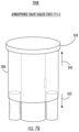
Referring to FIG. 4A, environment 400A illustrates various components of AW valve well 404. The AW valve well 404 may include a top 445 and a bottom 435 and/or an air portion 425 and a water portion 435. The air output channel 410, air input channel 412, and atmospheric channel 416 may be in the air portion 425. The atmospheric channel 416 may comprise a horizontally-oriented exit towards the top 345 and lip 432, the air input channel 412 may comprise a horizontally-oriented entrance towards the top 345, the air output channel 410 may comprise a vertically-oriented exit towards the top. The water input channel 408, water output channel 412, and balloon channel 414 may be in the water portion 435. The balloon channel 414 may comprise a vertically-oriented exit proximate the middle, the water input channel 408 may comprise a vertically-oriented entrance toward the bottom 455, and the water output channel 412 may comprise a vertically-oriented exit toward the bottom 455. In several embodiments, the lip 432 may enable one or more suction valve sets and/or valve interface mechanisms to couple to the AW valve well 404.
In several embodiments, the AW valve well 404 may change diameters one or more times. For example, the diameter changes in conjunction with vertical displacement of a valve may enable flow around the valve and through a channel. In the illustrated embodiment, the AW valve well may have a first diameter comprising the entrance/exits of the air input/ atmospheric channels 412, 416, a second diameter comprising the exit of the air output channel 410, a third diameter comprising the entrance/exit of the water input/ balloon channels 408, 414, and a fourth diameter comprising the exit of the water output channel 412. It will be appreciated that the orientation, size, and/or arrangement of one or more of the channels and/or flows may be modified in various embodiments without departing from the scope of this disclosure.
Referring to FIG. 4B, environment 400B illustrates a flow 438-1 through the AW valve well 404 in an air escape state 405-1. In the air escape state 405-1, flow 438-1 may enter via air input channel 406 and exit through the atmospheric channel 416. Further, in some embodiments, flow may be blocked through one or more of balloon channel 414, water input channel 408, and water output channel 412.
Referring to FIG. 4C, environment 400C illustrates a flow 438-2 through the AW valve well 404 in an air delivery state 405-2. In the air delivery state 405-2, flow 438-2 may enter via the air input channel 406 and exit through the air output channel 410. Further, in various embodiments, flow may be blocked through one or more of atmospheric channel 416, balloon channel 414, water input channel 408, and water output channel 412.
Referring to FIG. 4D, environment 400D illustrates a flow 438-3 through the AW valve well 404 in a water delivery state 405-3. In the water delivery state 405-3, flow 438-3 may enter via water input channel 408 and exit through the water output channel 412. Further, in various embodiments, flow may be blocked through one or more of the balloon channel 414, air output channel 410, air input channel 406, and atmospheric channel 416. In various embodiments, blocking flow at the air input channel 406 may cause pressure to build in a water source feeding the water input channel 408. In various such embodiments, pressure in the water source may cause fluid to flow from the water source to water input channel 408.
Referring to FIG. 4E, environment 400E illustrates a flow 438-4 through the AW valve well 404 in a balloon fill state 405-4. In the balloon fill state 405-4, flow 438-4 may enter via the water input channel 408 and exit through the balloon channel 414. Further, in many embodiments, flow may be blocked through one or more of the water output channel 412, air output channel 410, air input channel 406, and atmospheric channel 413.
FIGS. 5-12C illustrate various aspects of exemplary valve sets in environments 500, 600A, 600B, 700A, 700B, 800A-C, 900, 1000A, 1000B, 1100A, 1100B, 1200A-C, according to one or more embodiments described herein. In some embodiments, one or more components of FIGS. 5-12C may be the same or similar to one or more other components described herein. Environments 500-800C illustrate various aspects of a suction valve set 518 in conjunction with one or more components of suction valve well 304. Environments 900-1200C illustrate various aspects of an AW valve set 918 in conjunction with one or more components of AW valve well 404. In one or more embodiments described herein, fluid may flow through the valve wells based on the arrangement of one or more valves as positioned by one or more valve interface mechanisms. In many embodiments, one or more valves described herein may include a plurality of components configured to control fluid through a valve well. Embodiments are not limited in this context.
Referring to FIG. 5 , environment 500 illustrates suction valve set 518 in conjunction with suction valve well 304. Suction valve set 518 may include working channel valve 520, balloon valve 522, and atmospheric valve 524. The working channel valve 520 may include a working channel valve radial hole 540 that enables fluid to flow into the working channel valve 520 out of the bottom of the working channel valve 520. In several embodiments, the working channel valve 520 may be inserted into the working channel of suction valve well 304 to control flow therethrough. The balloon valve 522 may be inserted into balloon channel 314 of suction valve well 304 to control flow therethrough. The atmospheric valve 524 may be inserted into the atmospheric channel of suction valve well 304 to control flow therethrough. In many embodiments, one or more valves in suction valve set 518 may be integrated with one or more portions of a housing and/or valve interface mechanism corresponding to suction valve well 304.
In one or more embodiments, the atmospheric valve 524 may be configured to control fluid communication with the atmosphere from the interior of the suction valve well 304. In many embodiments, the atmospheric valve 524 may include a hole in a housing. In some embodiments, the atmospheric valve 524 may be operated by covering and/or uncovering the hole, such as with a finger or other mechanism. In several embodiments, the positioning and/or configuration of the valves in suction valve set 518 may be controlled by one or more components of a corresponding valve interface mechanism. For example, depressing a valve interface mechanism to a first stop may simultaneously shut off atmospheric suction via a seal on the underside of a cap and open working channel suction by pushing down the center of the working channel valve 520 to align the working channel valve radial hole 540 and the well radial hole.
Referring to FIG. 6A, environment 600A illustrates a balloon valve open state 615-1. In the balloon valve open state 615-1, the balloon valve 522 may allow flow through the balloon channel 314 by permitting flow through the necking portion 334 of balloon channel 314. Referring to FIG. 6B, environment 600B illustrates a balloon valve sealed state 615-2. In the balloon valve sealed state 615-2, the balloon valve 522 may prevent flow through balloon channel 314 by blocking flow through the necking portion 334 of balloon channel 314. In additional, or alternative embodiments, the default state of the balloon valve 522 may be the balloon valve sealed state 615-2 and the balloon valve 522 may be depressed toward the bottom 355 and below the necking portion 334 to transition into the balloon valve open state 615-1.
Referring to FIG. 7A, environment 700A illustrates an atmospheric valve open state 715-1. In the atmospheric valve open state 715-1, the atmospheric valve 524 may allow flow through the atmospheric channel 316 of suction valve well 304. Referring to FIG. 7B, environment 700B illustrates an atmospheric valve sealed state 715-2. In the atmospheric valve sealed state 715-2, the atmospheric valve 524 may prevent flow through atmospheric channel 316. As will be discussed in more detail below, in operation, fluid communication with the atmosphere may be provided through a passage/channel in, or created by, one or more components. Further, one or more components may be used to seal portions of the atmospheric channel 316 to facilitate control of fluid communication with the atmosphere by atmospheric valve 524. In some embodiments, atmospheric valve 524 may include a plurality of components configured to control fluid communication with the atmosphere.
Referring to FIG. 8A, environment 800A illustrates a working channel valve first sealed state 815-1. In the working channel valve first sealed state 815-1, the working channel valve 520 may prevent flow through well radial hole 336 by misaligning the working channel valve radial hole 540 with the well radial hole 336, such as with working channel valve 520 being positioned such that working channel valve radial hole 540 is above well radial hole 336. Referring to FIG. 8B, environment 800B illustrates a working channel valve open state 815-2. In the working channel valve open state 815-2, the working channel valve radial hole 540 and the well radial hole 336 may be aligned to permit suction flow through working channel 308. For example, the flow may enter through the bottom of the working channel valve 520 and exit through the well radial hole 336. Referring to FIG. 8C, environment 800C illustrates a working channel valve second sealed state 815-3. In the working channel valve second sealed state 815-3, the working channel valve 520 may prevent flow through well radial hole 336 by misaligning the working channel valve radial hole 540 with the well radial hole 336, such as with working channel valve 520 being positioned such that working channel radial hole 440 is below well radial hole 336.
Referring to FIG. 9 , environment 900 illustrates AW valve set 918 in conjunction with AW valve well 404. AW valve set 918 may include primary control valve 920, air input valve 922, and atmospheric valve 924. In several embodiments, the primary control valve 920 may be inserted into the AW valve well 404 to control, at least in part, the flow through one or more channels of the AW valve well 404. In various embodiments, the air input valve 922 may be inserted into the air input channel of the AW valve well 404 to control flow therethrough. In many embodiments, the atmospheric valve 924 may be inserted into the atmospheric channel of AW valve well 404 to control flow therethrough. In many embodiments, one or more valves in AW valve set 918 may be integrated with one or more portions of a housing and/or valve interface mechanism corresponding to AW valve well 404.
In one or more embodiments, the atmospheric valve 924 may be configured to control fluid communication with the atmosphere from the interior of the AW valve well 404. In many embodiments, the atmospheric valve 924 may include a hole in a housing. In some embodiments, the atmospheric valve 924 may be operated by covering and/or uncovering the hole, such as with a finger or other mechanism. In several embodiments, the positioning and/or configuration of the valves in AW valve set 918 may be controlled by one or more components of a corresponding valve interface mechanism. In some embodiments, one or more portions of the atmospheric channel 416 may be included in the primary control valve 920. In some such embodiments, the atmospheric channel 416 may comprise one or more passages through at least a portion of the primary control valve 920. For example, the atmospheric channel 416 may comprise a hole in the top of the primary control valve 920 in fluid communication with a radial hole in the primary control valve 920 proximate the air input channel 406. In such examples, covering the hole may direct air flow into the air output channel 410 and down a working channel of an endoscope.
Referring to FIG. 10A, environment 1000A illustrates an atmospheric valve open state. In the atmospheric valve open state, the atmospheric valve 924 may allow flow through the atmospheric channel of AW valve well 404. Referring to FIG. 10B, environment 1000B illustrates an atmospheric valve sealed state 1015-2. In the atmospheric valve sealed state 1015-2, the atmospheric valve 924 may prevent flow through atmospheric channel of AW valve well 404. As will be discussed in more detail below, in operation, fluid communication with the atmosphere may be provided through a passage/channel in, or created by, one or more components (e.g., primary control valve 920). Further, one or more components may be used to seal portions of the atmospheric channel 316 to facilitate control of fluid communication with the atmosphere by atmospheric valve 924. In some embodiments, atmospheric valve 924 may include a plurality of components configured to control fluid communication with the atmosphere.
Referring to FIG. 11A, environment 1100A illustrates an air input valve open state 1115-1. In the air input valve open state 1115-1, the air input valve 522 may allow flow through the air input channel of AW valve well 404. Referring to FIG. 11B, environment 1100B illustrates an air input valve sealed state 1115-2. In the air input valve sealed state 1115-2, the air input valve 922 may prevent flow through the air input channel of AW valve well 404. In some embodiments, sealing the air input channel may cause a fluid source (e.g., water reservoir) to be pressurized, thereby enabling/causing fluid to flow into the AW valve well 404 via water input channel 408.
Referring to FIG. 12A, environment 1200A illustrates a primary valve sealed state 1215-1. In the primary valve sealed state 1215-1, the primary control valve 920 may prevent flow through one or more of the balloon channel 414, water input channel 408, and water output channel 412. Referring to FIG. 12B, environment 1200B illustrates a primary valve water output state 1215-2. In the primary valve water output state 1215-2, the primary control valve 920 may be positioned to block flow through balloon channel 414 and permit flow from water input channel 408 to water output channel 412. In various embodiments, primary control valve 920 may utilize changes in diameter in AW valve well 404 to control flow. Referring to FIG. 12C, environment 1200C illustrates a primary valve balloon fill state 1215-3. In the primary valve balloon fill state 1215-3, the primary control valve 920 may be positioned to block flow through water output channel 412 and permit flow from water input channel 408 to balloon channel 414. In various embodiments, one or more features of primary control valve 920 may operate as valves for multiple channels. In some embodiments, one or more features of primary control valve 920 may comprise one or more channels, or one or more portions thereof. For example, primary control valve 920 may comprise atmospheric channel 416. FIG. 13 illustrates an exemplary AW valve assembly 1302 in environment 1300, according to one or more embodiments described herein. In many embodiments, a cross section of one or more portions of AW valve assembly 1302 may be illustrated in environment 1300. In some embodiments, one or more components of FIG. 13 may be the same or similar to one or more other components described herein. AW valve assembly 1302 includes an AW valve well 1304, an AW valve set, and a valve interface mechanism. The AW valve well 1304 includes air input channel 1306, water input channel 1308, air output channel 1310, water output channel 1312, balloon channel 1314, and lip 1332. The AW valve set may include primary control valve 1320 with interior channel 1321 and atmospheric channel 1316, air input valve 1322, and atmospheric valve 1324. In the illustrated embodiment, the air input valve 1322 and the atmospheric valve 1324 may include, or be included in, one or more portions of the valve interface mechanism. The valve interface mechanism includes biasing members 1328-1, 1328-2, toggle 1350, cam 1352 with atmospheric valve 1324, housing 1354, and linkages 1364-1, 1364-2. In one or more embodiments described herein, toggle 1350 may be moved to control the flow of fluid through AW valve assembly 1302, such as by switching between an air escape state 1305-1, an air delivery state 1305-2, a water delivery state 1305-3, and a balloon fill state 1305-4. Embodiments are not limited in this context.
In some embodiments, the linkage 1364-1 may be attached to, or included in, primary control valve 1320. In various embodiments, air input valve 1322 may be coupled to linkage 1364-1 via biasing member 1328-1. In many embodiments, linkage 1364-2 may seat in the AW valve well 1304 to enable biasing member 1328-2 to push against linkage 1364-1 and bias primary control valve 1320 toward the top. In several embodiments, primary control valve 1320 may be able to slide up and down through linkage 1364-2. In the illustrated embodiment, housing 1354 may couple to the AW valve well 1304 via lip 1332. The housing 1354 may provide a rigid mounting point for one or more components of AW valve assembly 1302, such as for toggle 1350 and cam 1352 to rotatably couple to.
In many embodiments, cam 1352 may enable motion of toggle 1350 to be translated into linear motion of primary control valve 1320. In various embodiments, cam 1352 may include a profile with one or more steps, such as to seal atmospheric channel 1316 and/or move primary control valve 1320 toward the bottom. As shown in the illustrated embodiment, cam 1352 may include three steps or levels with a first step corresponding to the air delivery state 1305-2, a second step corresponding to the water delivery state 1305-3, and a third step corresponding to the balloon fill state 1305-4. Accordingly, articulating toggle 1350 between different positions may cause cam 1352 to contact and/or move primary control valve 1320 to switch between the air escape state 1305-1, the air delivery state 1305-2, the water delivery state 1305-3, and the balloon fill state 1305-4. In several embodiments, a spring may be coupled to toggle 1350 to bias the toggle 1350, and thereby the primary control valve 1320, into a specific position or state.
Referring to air escape state 1305-1, the cam 1352 may be positioned out of contact with the primary control valve 1320 to enable fluid from air input valve 1322 through the interior channel 1321 and escape to atmosphere through the top of the primary control valve 1320 via atmospheric channel 1316. With cam 1352 positioned out of contact with the primary control valve 1320, biasing member 1328-2 may force primary control valve 1320 toward the top of the AW valve assembly 1302. Further, biasing member 1328-1 may ensure that air input valve 1322 is in an open state due to biasing member 1328-2 forcing primary control valve 1320 toward the top of the AW valve assembly 1302.
Referring to air delivery state 1305-2, the first step of cam 1352 may be positioned in contact with the primary control valve 1320 such that the first step of the cam 1352 acts as atmospheric valve 1324 and seals atmospheric channel 1316. In the air delivery state 1305-2, fluid may flow from the air input channel 1306 to the air output channel 1310 via interior channel 1321. With the first step of cam 1352 positioned in contact with the primary control valve 1320, biasing member 1328-2 may force primary control valve 1320 toward the top of the AW valve assembly 1302 to facilitate sealing between the atmospheric channel 1316 and the first step of the cam 1352. Further, the first step of cam 1352 may only slightly compress biasing member 1328-2 and slightly force linkage 1364-1 downward such that biasing member 1328-1 is still able to ensure that air input valve 1322 is in an open state due to biasing member 1328-2 forcing primary control valve 1320 toward the top of the AW valve assembly 1302.
Referring to water delivery state 1305-3, the second step of cam 1352 may be positioned in contact with the primary control valve 1320 such that the second step of the cam 1352 acts as atmospheric valve 1324 and seals atmospheric channel 1316. Additionally, positioning the second step of cam 1352 in contact with the primary control valve 1320 may force the primary control valve 1320 toward the bottom, causing air input valve 1322 to seal against air input channel 1306 and placing water input channel 1308 in fluid communication with water output channel 1312. In the water delivery state 1305-3, fluid flow from the air input channel 1306 may be blocked by air input valve 1322 and fluid may flow from the water input channel 1308 to the water output channel 1312. With the second step of cam 1352 positioned in contact with the primary control valve 1320, biasing member 1328-2 may force primary control valve 1320 toward the top of the AW valve assembly 1302 to facilitate sealing between the atmospheric channel 1316 and the second step of the cam 1352. Further, the second step of cam 1352 may compress biasing member 1328-2 and force linkage 1364-1 downward such that biasing member 1328-1 forces air input valve 1322 downward to seal air input channel 1306.
Referring to balloon fill state 1305-4, the third step of cam 1352 may be positioned in contact with the primary control valve 1320 such that the third step of the cam 1352 acts as atmospheric valve 1324 and seals atmospheric channel 1316. Additionally, positioning the third step of cam 1352 in contact with the primary control valve 1320 may force the primary control valve 1320 toward the bottom, causing air input valve 1322 to seal against air input channel 1306 and placing water input channel 1308 in fluid communication with balloon channel 1314. In the balloon fill state 1305-4, fluid flow from the air input channel 1306 may be blocked by air input valve 1322 and fluid may flow from the water input channel 1308 to the balloon channel 1314. With the third step of cam 1352 positioned in contact with the primary control valve 1320, biasing member 1328-2 may force primary control valve 1320 toward the top of the AW valve assembly 1302 to facilitate sealing between the atmospheric channel 1316 and the third step of the cam 1352. Further, the third step of cam 1352 may compress biasing member 1328-2 and force linkage 1364-1 downward such that biasing member 1328-1 forces air input valve 1322 downward to seal air input channel 1306.
FIGS. 14A-14E illustrate various aspects of an exemplary AW valve assembly 1402 in environments 1400A-E, according to one or more embodiments described herein. In many embodiments, a cross section of one or more portions of AW valve assembly 1402 may be illustrated in environments 1400A-E. In some embodiments, one or more components of FIGS. 14A-14E may be the same or similar to one or more other components described herein. AW valve assembly 1402 includes an AW valve well 1404, an AW valve set, and a valve interface mechanism 1426. In the illustrated embodiment, AW valve well 1404 is be the same as AW valve well 1304. Accordingly, fewer components of AW valve well 1404 are labeled for simplicity. The AW valve set may include air input valve 1422 and primary control valve 1420 with interior channel 1421, atmospheric channel 1416, and radial air hole 1466. In the illustrated embodiment, the air input valve 1422 may include, or be included in, one or more portions of the primary control valve 1420 and/or the valve interface mechanism 1426. The valve interface mechanism 1426 includes housing 1454, knob 1456, interface 1458, slot cam 1460, cam pin 1462, and linkage 1464. In one or more embodiments described herein, knob 1456 may be rotated, such as via interface 1458, to control the flow of fluid through AW valve assembly 1402. Accordingly, in FIGS. 14A-14E, respectively, environment 1400B may illustrate one or more aspects of an air escape state, environment 1400C may illustrate one or more aspects of an air delivery state, environment 1400D may illustrate one or more aspects of a water delivery state, and environment 1400E may illustrate one or more aspects of a balloon fill state. Embodiments are not limited in this context.
Referring to environment 1400A, in some embodiments, the linkage 1464 may be attached to, or included in, primary control valve 1420. In various embodiments, air input valve 1422 may be attached to, or included in, primary control valve 1420. In many embodiments, linkage 1464 may be disposed within interior channel 1421. In other embodiments, interior channel 1421 may be disposed within linkage 1464. In the illustrated embodiment, housing 1454 may couple to the AW valve well 1404 via lip 1332. The housing 1454 may provide a rigid mounting point for one or more components of AW valve assembly 1402, such as for knob 1456 to rotatably couple to.
In many embodiments, knob 1456 may be rotated to control the position of the primary control valve 1420 in AW valve well 1404. In many such embodiments, rotating knob 1456 may cause the cam pin 1462 to follow the profile of the slot cam 1460 and force the primary control valve 1420 up or down, as will be described in more detail below with respect to environments 1400D, 1400E. In some embodiments, rotating knob 1456, such as via interface 1458, may cause block flow through one or more of atmospheric channel 1416, interior channel 1421, and radial air hole 1466. For instance, rotating knob 1456 may block fluid communication between radial air hole 1466 and atmospheric channel 1416. In some embodiments, radial air hole 1466 may include a plurality of holes provided access to interior channel 1421.
In several embodiments, a torsional spring may be coupled to knob 1456 to bias the knob 1456, and thereby the primary control valve 1420, into a specific position. In the illustrated embodiment, knob 1456 is biased such that cam pin 1462 is in a flat portion in the middle of slot cam 1460. However, in other embodiments, knob 1456 is biased such that cam pin 1462 is on one side or the other of slot cam 1460. Further, in other embodiments, slot cam 1460 may take on a variety of geometries. For instance, slot cam 1460 may include flat portions on each side. In another instance, slot cam 1460 may include additional angled sections, such as additional angled sections configured to further raise or lower primary control valve 1420, and/or close atmospheric channel 1416. In one or more embodiments, the geometry of the slot cam 1460 may provide tactile feedback. For example, the flat portions and/or different angles of sections may provide tactile feedback. An alternative slot cam geometry is included in environments 1400B, 1400C for illustrative purposes.
Referring to FIG. 14B, environment 1400B may illustrate an air escape state of AW valve assembly 1402. In the air escape state, flow 1438-1 may enter through the air input channel 1406, pass through the radial air hole 1466, enter interior channel 1421, and exit through the atmospheric channel 1416 at the top of AW valve well assembly 1402. Referring to FIG. 14C, environment 1400C may illustrate an air delivery state of AW valve assembly 1402. In the air delivery state, flow 1438-2 may enter through the air input channel 1406, pass through the interior channel 1421 via radial air hole 1466, and exit through the air output channel 1410. In various embodiments, the atmospheric channel 1416 may be blocked to transition from the air escape state to the air delivery state. In some embodiments, rotation of knob 1456 may cause the atmospheric channel 1416 to be blocked. In some such embodiments, knob 1456 may be depressed to control the position of the primary control valve 1420. In other embodiments, depressing knob 1456 may cause the atmospheric channel 1416 to be blocked. In still other embodiments, a finger may be placed over atmospheric channel 1416 to block it.
Referring to FIG. 14D, environment 1400D may illustrate aspects of AW valve assembly 1402 in a water delivery state. Knobs 1456-1, 1456-2 may illustrate front and side views of knob 1456, respectively. In the illustrated embodiment, clockwise 1480 rotation of knob 1456 may force cam pin 1462 to force primary control valve 1420 downward a first amount. In various embodiments, the downward motion of the primary control valve 1420 may place the water input channel 1408 in fluid communication with the water output channel 1412 and/or cause air input valve 1422 to block flow from air input channel 1406. In many embodiments, a biasing member may force air input valve 1422 against air input channel 1406 to block flow from air input channel 1406 in a manner similar to the manner illustrated and described with respect to FIG. 13 .
Referring to FIG. 14E, environment 1400E may illustrate aspects of AW valve assembly 1402 in a balloon fill state. Knobs 1456-1, 1456-2 may illustrate front and side views of knob 1456, respectively. In the illustrated embodiment, counterclockwise 1482 rotation of knob 1456 may force cam pin 1462 to force primary control valve 1420 downward a second amount, wherein the second amount is greater than the first amount. In various embodiments, the downward motion of the primary control valve 1420 may place the water input channel 1408 in fluid communication with the balloon channel 1414 and/or cause air input valve 1422 to block flow from air input channel 1406. In many embodiments, a biasing member may force air input valve 1422 against air input channel 1406 to block flow from air input channel 1406 in a manner similar to the manner illustrated and described with respect to FIG. 13 .
The medical devices of the present disclosure are not limited, and may include a variety of medical devices for accessing body passageways, including, for example, duodenoscopes, catheters, ureteroscopes, bronchoscopes, colonoscopes, arthroscopes, cystoscopes, hysteroscopes, EUS endoscopes, and the like. In various embodiments, the valve assemblies, or components thereof, described herein may include one or more (e.g., as a single or set of units) of a mounting point, mechanical coupler, bearing, seal, O-ring, actuator, valve, diaphragm, gasket, housing, connector, structural member, manifold, ergonomic features (e.g., finger/thumb grooves, padding, grip, application of mechanical advantage, and the like), spring, bellow, cantilever biasing member, torsional biasing member, linear biasing member, flapper valve, skirt, fin, disc, channel, cavity, lumen, and the like. In many embodiments, one or more components described herein may be constructed utilizing a variety of devices, technologies and/or processes, such as three-dimensional (3D) printing, multi-axis computer numeric control (CNC) machines, additive manufacturing, subtractive manufacturing, injection molding, computer aided design (CAD) programs, path planning programs, machining, forging, casting, and the like.
All of the devices and/or methods disclosed and claimed herein can be made and executed without undue experimentation in light of the present disclosure. While the devices and methods of this disclosure have been described in terms of preferred embodiments, it may be apparent to those of skill in the art that variations can be applied to the devices and/or methods and in the steps or in the sequence of steps of the method described herein without departing from the concept, spirit and scope of the disclosure. All such similar substitutes and modifications apparent to those skilled in the art are deemed to be within the spirit, scope and concept of the disclosure as defined by the appended claims.

Claims (13)

What is claimed is:
1. A medical device, comprising:
a valve set including a primary control valve, an air input valve, and an atmospheric valve, the primary control valve configured to control flow between the water input channel, the water output channel, and the balloon channel of the valve well, the air input valve configured to control flow through the air input channel of the valve well, and the atmospheric valve configured to control flow through the atmospheric channel;
a valve interface mechanism including a set of one or more biasing members and a user interface mechanism, the user interface mechanism comprising a toggle coupled to a cam comprising a plurality of steps, the toggle operable between a first state, a second state, a third state, and a fourth state, the first state comprising the valve set configured to place the air input channel in fluid communication with the atmospheric channel, the second state comprising the valve set configured to place the air input channel in fluid communication with an air output channel, the third state comprising the valve set configured to place the water input channel in fluid communication with the water output channel, and the fourth state comprising the valve set configured to place the water input channel in fluid communication with the balloon channel,
wherein in the first state the air input valve permits flow through the air input channel and atmospheric valve permits flow through the atmospheric channel,
wherein in the second state the air input valve permits flow through the air input channel and the atmospheric valve blocks flow through the atmospheric valve,
wherein in the third state the primary control valve permits flow from the water input channel to the water output channel and the air input valve blocks flow through the air input channel,
wherein in the fourth state, the primary control valve permits flow from the water input channel to the balloon channel and the air input valve blocks flow through the air input channel,
wherein the cam is configured to translate the motion of the toggle into linear motion of the primary control valve, and
wherein each of the plurality of steps of the cam causes a different amount of linear motion of the primary control valve.
2. The medical device of claim 1, the plurality of steps comprising a first step corresponding to the second state, a second step corresponding to the third state, and a third step corresponding to the fourth state.
3. A medical device, comprising:
a valve set including a primary control valve, an air input valve, and an atmospheric valve, the primary control valve configured to control flow between the water input channel, the water output channel, and the balloon channel of the valve well, the air input valve configured to control flow through the air input channel of the valve well, and the atmospheric valve configured to control flow through the atmospheric channel;
a valve interface mechanism including a set of one or more biasing members and a user interface mechanism, the user interface mechanism comprising a toggle coupled to a cam comprising a plurality of steps, the toggle operable between a first state, a second state, a third state, and a fourth state, the first state comprising the valve set configured to place the air input channel in fluid communication with the atmospheric channel, the second state comprising the valve set configured to place the air input channel in fluid communication with an air output channel, the third state comprising the valve set configured to place the water input channel in fluid communication with the water output channel, and the fourth state comprising the valve set configured to place the water input channel in fluid communication with the balloon channel,
wherein in the first state the air input valve permits flow through the air input channel and atmospheric valve permits flow through the atmospheric channel,
wherein in the second state the air input valve permits flow through the air input channel and the atmospheric valve blocks flow through the atmospheric valve,
wherein in the third state the primary control valve permits flow from the water input channel to the water output channel and the air input valve blocks flow through the air input channel,
wherein in the fourth state, the primary control valve permits flow from the water input channel to the balloon channel and the air input valve blocks flow through the air input channel, and
wherein each of the plurality of steps is configured to seal the atmospheric channel.
4. The medical device of claim 1, the toggle configured to receive input to operate the user interface to one or more of the first state, the second state, the third state, and the fourth state.
5. The medical device of claim 1, the set of one or more biasing members comprising a first biasing member to bias the primary control valve toward a top of the valve well.
6. The medical device of claim 5, the set of one or more biasing members comprising a second biasing member to couple the primary control valve to the air input valve.
7. The medical device of claim 1, the set of one or more biasing members comprising a biasing member to bias the air input valve against the air input channel in the third and fourth states.
8. The medical device of claim 7, the biasing member to prevent the air input valve from blocking the air input channel in the first and second states.
9. The medical device of claim 3, the toggle configured to receive input to operate the user interface to one or more of the first state, the second state, the third state, and the fourth state.
10. The medical device of claim 3, the set of one or more biasing members comprising a first biasing member to bias the primary control valve toward a top of the valve well.
11. The medical device of claim 10, the set of one or more biasing members comprising a second biasing member to couple the primary control valve to the air input valve.
12. The medical device of claim 3, the set of one or more biasing members comprising a biasing member to bias the air input valve against the air input channel in the third and fourth states.
13. The medical device of claim 12, the biasing member to prevent the air input valve from blocking the air input channel in the first and second states.
US17/208,772 2020-03-24 2021-03-22 Motion translation and interface devices, systems, and methods for endoscope valves Active 2041-08-14 US11812927B2 (en)

Priority Applications (2)

Application Number Priority Date Filing Date Title
US17/208,772 US11812927B2 (en) 2020-03-24 2021-03-22 Motion translation and interface devices, systems, and methods for endoscope valves
US18/482,226 US20240032774A1 (en) 2020-03-24 2023-10-06 Motion translation and interface devices, systems, and methods for endoscope valves

Applications Claiming Priority (7)

Application Number Priority Date Filing Date Title
US202062994018P 2020-03-24 2020-03-24
US202062994008P 2020-03-24 2020-03-24
US202062994015P 2020-03-24 2020-03-24
US202062994024P 2020-03-24 2020-03-24
US202062994021P 2020-03-24 2020-03-24
US202062994019P 2020-03-24 2020-03-24
US17/208,772 US11812927B2 (en) 2020-03-24 2021-03-22 Motion translation and interface devices, systems, and methods for endoscope valves

Related Child Applications (1)

Application Number Title Priority Date Filing Date
US18/482,226 Continuation US20240032774A1 (en) 2020-03-24 2023-10-06 Motion translation and interface devices, systems, and methods for endoscope valves

Publications (2)

Publication Number Publication Date
US20210298571A1 US20210298571A1 (en) 2021-09-30
US11812927B2 true US11812927B2 (en) 2023-11-14

Family

ID=75478300

Family Applications (8)

Application Number Title Priority Date Filing Date
US17/208,794 Active 2041-07-12 US12011144B2 (en) 2020-03-24 2021-03-22 Devices, systems, and methods for fluid control in endoscope systems
US17/208,733 Pending US20210298568A1 (en) 2020-03-24 2021-03-22 Devices, systems, and methods for controlling fluids in endoscope systems
US17/208,706 Pending US20210298567A1 (en) 2020-03-24 2021-03-22 Interface and motion translation devices, systems, and methods for endoscope valves
US17/208,818 Pending US20210298570A1 (en) 2020-03-24 2021-03-22 Devices, systems, and methods for endoscope fluidics
US17/208,750 Pending US20210298569A1 (en) 2020-03-24 2021-03-22 Devices, systems, and methods for endoscope valve control
US17/208,772 Active 2041-08-14 US11812927B2 (en) 2020-03-24 2021-03-22 Motion translation and interface devices, systems, and methods for endoscope valves
US18/482,226 Pending US20240032774A1 (en) 2020-03-24 2023-10-06 Motion translation and interface devices, systems, and methods for endoscope valves
US18/666,605 Pending US20240298877A1 (en) 2020-03-24 2024-05-16 Devices, systems, and methods for fluid control in endoscope systems

Family Applications Before (5)

Application Number Title Priority Date Filing Date
US17/208,794 Active 2041-07-12 US12011144B2 (en) 2020-03-24 2021-03-22 Devices, systems, and methods for fluid control in endoscope systems
US17/208,733 Pending US20210298568A1 (en) 2020-03-24 2021-03-22 Devices, systems, and methods for controlling fluids in endoscope systems
US17/208,706 Pending US20210298567A1 (en) 2020-03-24 2021-03-22 Interface and motion translation devices, systems, and methods for endoscope valves
US17/208,818 Pending US20210298570A1 (en) 2020-03-24 2021-03-22 Devices, systems, and methods for endoscope fluidics
US17/208,750 Pending US20210298569A1 (en) 2020-03-24 2021-03-22 Devices, systems, and methods for endoscope valve control

Family Applications After (2)

Application Number Title Priority Date Filing Date
US18/482,226 Pending US20240032774A1 (en) 2020-03-24 2023-10-06 Motion translation and interface devices, systems, and methods for endoscope valves
US18/666,605 Pending US20240298877A1 (en) 2020-03-24 2024-05-16 Devices, systems, and methods for fluid control in endoscope systems

Country Status (5)

Country Link
US (8) US12011144B2 (en)
EP (6) EP4125535A1 (en)
CN (6) CN115720504A (en)
AU (6) AU2021244310B2 (en)
WO (6) WO2021194966A1 (en)

Families Citing this family (1)

* Cited by examiner, † Cited by third party
Publication number Priority date Publication date Assignee Title
US20230172430A1 (en) * 2021-12-02 2023-06-08 Boston Scientific Scimed, Inc. Devices, systems, and methods for endoscopic valves

Citations (28)

* Cited by examiner, † Cited by third party
Publication number Priority date Publication date Assignee Title
US4061250A (en) * 1975-05-31 1977-12-06 Tetsuya Tada Depress button type sprayer
US4694821A (en) * 1984-10-24 1987-09-22 Fuji Photo Optical Co., Ltd. Air feed control device for an endoscope
US4800869A (en) * 1987-02-13 1989-01-31 Olympus Optical Co. Ltd. Endoscope
JP2000217777A (en) 1999-01-28 2000-08-08 Olympus Optical Co Ltd Bending operation unit for endoscope
US6334844B1 (en) * 1999-08-17 2002-01-01 Fuji Photo Optical Co., Ltd. Mechanical- and electrical-mode changeable endoscope conduit controller
US6346075B1 (en) 1999-02-01 2002-02-12 Fuji Photo Optical Co., Ltd. Air and water supply valve structure in endoscope
JP2007111266A (en) 2005-10-20 2007-05-10 Olympus Medical Systems Corp Conduit switching device for endoscope
US20100049001A1 (en) * 2008-08-22 2010-02-25 Kenji Yamane Endoscope sucking operation apparatus
US20110208003A1 (en) * 2010-02-24 2011-08-25 Fujifilm Corporation Suction conduit device of endoscope that prevents clogging
US20110298169A1 (en) * 2008-10-13 2011-12-08 Nguyen Nick N Endoscope channel separator
EP2431062A1 (en) 2010-09-17 2012-03-21 Karl Storz GmbH & Co. KG Medical instrument for suction and rinsing
US20120088973A1 (en) * 2010-10-12 2012-04-12 Yasuhiko Morimoto Switching valve assembly for endoscope
US20120088975A1 (en) * 2010-10-12 2012-04-12 Yasuhiko Morimoto Switching valve assembly for endoscope
US20160302646A1 (en) * 2014-04-24 2016-10-20 Olympus Corporation Endoscope button unit and endoscope
US20180361034A1 (en) * 2017-06-16 2018-12-20 Karl Storz Se & Co. Kg Medical push button valve
US20190125167A1 (en) * 2016-06-29 2019-05-02 Olympus Corporation Endoscope button
US20190350441A1 (en) * 2017-02-01 2019-11-21 Olympus Corporation Endoscope valve and endoscope
US20190350445A1 (en) * 2017-02-01 2019-11-21 Olympus Corporation Endoscope valve and endoscope
US20190350444A1 (en) * 2017-02-01 2019-11-21 Olympus Corporation Endoscope valve and endoscope
US20190350446A1 (en) * 2017-02-01 2019-11-21 Olympus Corporation Endoscope valve and endoscope
WO2019225562A1 (en) 2018-05-21 2019-11-28 オリンパス株式会社 Endoscope tube switching device
US20200016637A1 (en) * 2018-07-10 2020-01-16 United States Endoscopy Group, Inc. Air/water channel pre-cleaning adapter
US20200187756A1 (en) * 2017-08-24 2020-06-18 ERBE-USA, Inc. Apparatus for improved visualization for endoscopic procedures
US20200355281A1 (en) * 2019-05-07 2020-11-12 Boston Scientific Scimed, Inc. Devices, systems, and methods for medical cleaning valves
US20200375434A1 (en) * 2019-05-30 2020-12-03 Boston Scientific Scimed, Inc. Medical valve
US20200386330A1 (en) * 2019-06-10 2020-12-10 Boston Scientific Scimed, Inc. Medical cleaning valve
US20210007586A1 (en) * 2019-07-11 2021-01-14 Boston Scientific Scimed, Inc. Endoscope air/water flush adaptor and method
US20210076914A1 (en) * 2018-04-16 2021-03-18 Olympus Corporation Fluid control device for endoscope, and endoscope

Family Cites Families (9)

* Cited by examiner, † Cited by third party
Publication number Priority date Publication date Assignee Title
US4261343A (en) * 1978-03-28 1981-04-14 Kabushiki Kaisha Medos Kenkyusho Endoscope
US4736732A (en) * 1985-09-03 1988-04-12 Olympus Optical Co., Ltd. Endoscopic fluid changing device
JPS63143025A (en) * 1986-12-04 1988-06-15 オリンパス光学工業株式会社 Suction controller of endoscope
US5027791A (en) * 1988-12-22 1991-07-02 Asahi Kogaku Kogyo Kabushiki Kaisha Air and water supply apparatus for endoscope
JP3414531B2 (en) * 1994-12-27 2003-06-09 オリンパス光学工業株式会社 Endoscope conduit switching device
ATE556641T1 (en) * 2009-03-30 2012-05-15 Olympus Medical Systems Corp ENDOSCOPIC FLUID CONTROL DEVICE
JP5722510B1 (en) * 2013-08-27 2015-05-20 オリンパスメディカルシステムズ株式会社 Endoscope fluid control system
JP5866329B2 (en) * 2013-11-28 2016-02-17 富士フイルム株式会社 Endoscope duct switching device and endoscope
WO2019225561A1 (en) * 2018-05-21 2019-11-28 オリンパス株式会社 Disposable endoscope tube switching device

Patent Citations (29)

* Cited by examiner, † Cited by third party
Publication number Priority date Publication date Assignee Title
US4061250A (en) * 1975-05-31 1977-12-06 Tetsuya Tada Depress button type sprayer
US4694821A (en) * 1984-10-24 1987-09-22 Fuji Photo Optical Co., Ltd. Air feed control device for an endoscope
US4800869A (en) * 1987-02-13 1989-01-31 Olympus Optical Co. Ltd. Endoscope
JP2000217777A (en) 1999-01-28 2000-08-08 Olympus Optical Co Ltd Bending operation unit for endoscope
US6346075B1 (en) 1999-02-01 2002-02-12 Fuji Photo Optical Co., Ltd. Air and water supply valve structure in endoscope
US6334844B1 (en) * 1999-08-17 2002-01-01 Fuji Photo Optical Co., Ltd. Mechanical- and electrical-mode changeable endoscope conduit controller
JP2007111266A (en) 2005-10-20 2007-05-10 Olympus Medical Systems Corp Conduit switching device for endoscope
US20100049001A1 (en) * 2008-08-22 2010-02-25 Kenji Yamane Endoscope sucking operation apparatus
US20110298169A1 (en) * 2008-10-13 2011-12-08 Nguyen Nick N Endoscope channel separator
US20110208003A1 (en) * 2010-02-24 2011-08-25 Fujifilm Corporation Suction conduit device of endoscope that prevents clogging
US8568303B2 (en) * 2010-02-24 2013-10-29 Fujifilm Corporation Suction conduit device of endoscope that prevents clogging
EP2431062A1 (en) 2010-09-17 2012-03-21 Karl Storz GmbH & Co. KG Medical instrument for suction and rinsing
US20120088973A1 (en) * 2010-10-12 2012-04-12 Yasuhiko Morimoto Switching valve assembly for endoscope
US20120088975A1 (en) * 2010-10-12 2012-04-12 Yasuhiko Morimoto Switching valve assembly for endoscope
US20160302646A1 (en) * 2014-04-24 2016-10-20 Olympus Corporation Endoscope button unit and endoscope
US20190125167A1 (en) * 2016-06-29 2019-05-02 Olympus Corporation Endoscope button
US20190350441A1 (en) * 2017-02-01 2019-11-21 Olympus Corporation Endoscope valve and endoscope
US20190350445A1 (en) * 2017-02-01 2019-11-21 Olympus Corporation Endoscope valve and endoscope
US20190350444A1 (en) * 2017-02-01 2019-11-21 Olympus Corporation Endoscope valve and endoscope
US20190350446A1 (en) * 2017-02-01 2019-11-21 Olympus Corporation Endoscope valve and endoscope
US20180361034A1 (en) * 2017-06-16 2018-12-20 Karl Storz Se & Co. Kg Medical push button valve
US20200187756A1 (en) * 2017-08-24 2020-06-18 ERBE-USA, Inc. Apparatus for improved visualization for endoscopic procedures
US20210076914A1 (en) * 2018-04-16 2021-03-18 Olympus Corporation Fluid control device for endoscope, and endoscope
WO2019225562A1 (en) 2018-05-21 2019-11-28 オリンパス株式会社 Endoscope tube switching device
US20200016637A1 (en) * 2018-07-10 2020-01-16 United States Endoscopy Group, Inc. Air/water channel pre-cleaning adapter
US20200355281A1 (en) * 2019-05-07 2020-11-12 Boston Scientific Scimed, Inc. Devices, systems, and methods for medical cleaning valves
US20200375434A1 (en) * 2019-05-30 2020-12-03 Boston Scientific Scimed, Inc. Medical valve
US20200386330A1 (en) * 2019-06-10 2020-12-10 Boston Scientific Scimed, Inc. Medical cleaning valve
US20210007586A1 (en) * 2019-07-11 2021-01-14 Boston Scientific Scimed, Inc. Endoscope air/water flush adaptor and method

Non-Patent Citations (4)

* Cited by examiner, † Cited by third party
Title
International Search Report and Written Opinion for the International Patent Application No. PCT/US2021/023478, dated Jun. 10, 2021, 49 pages.
International Search Report and Written Opinion for the International Patent Application No. PCT/US2021/023479, dated Jul. 9, 2021, 12 pages.
International Search Report and Written Opinion for the International Patent Application No. PCT/US2021/023482, dated Jul. 9, 2021, 12 pages.
International Search Report and Written Opinion for the International Patent Application No. PCT/US2021/023484, dated Jul. 9, 2021, 12 pages.

Also Published As

Publication number Publication date
AU2021241497A1 (en) 2022-10-06
CN115666359A (en) 2023-01-31
EP4125539A1 (en) 2023-02-08
AU2021244310B2 (en) 2024-02-08
CN115697172A (en) 2023-02-03
US20210298571A1 (en) 2021-09-30
US12011144B2 (en) 2024-06-18
WO2021194967A1 (en) 2021-09-30
EP4125537A1 (en) 2023-02-08
WO2021194968A1 (en) 2021-09-30
AU2021244309B2 (en) 2024-08-29
AU2021244308B2 (en) 2024-02-22
AU2021244310A1 (en) 2022-10-06
US20240032774A1 (en) 2024-02-01
AU2021241497B2 (en) 2024-05-09
AU2021244306B2 (en) 2024-02-08
US20210298567A1 (en) 2021-09-30
CN115666358A (en) 2023-01-31
EP4125535A1 (en) 2023-02-08
EP4125540A1 (en) 2023-02-08
AU2021241499B2 (en) 2024-09-19
US20210298568A1 (en) 2021-09-30
CN115720504A (en) 2023-02-28
CN115605120A (en) 2023-01-13
US20210298570A1 (en) 2021-09-30
US20240298877A1 (en) 2024-09-12
CN115605121A (en) 2023-01-13
WO2021194973A1 (en) 2021-09-30
WO2021194969A1 (en) 2021-09-30
US20210298569A1 (en) 2021-09-30
AU2021244306A1 (en) 2022-10-06
WO2021194971A1 (en) 2021-09-30
AU2021244308A1 (en) 2022-10-06
EP4125538A1 (en) 2023-02-08
US20210298572A1 (en) 2021-09-30
AU2021244309A1 (en) 2022-10-06
EP4125536A1 (en) 2023-02-08
WO2021194966A1 (en) 2021-09-30
EP4125540B1 (en) 2024-08-07
AU2021241499A1 (en) 2022-10-06

Similar Documents

Publication Publication Date Title
US20240298877A1 (en) Devices, systems, and methods for fluid control in endoscope systems
US11793990B2 (en) Complex irrigation/suction flow path in a medical device
JP2004223121A (en) Duct switching valve of endoscope
US20230172430A1 (en) Devices, systems, and methods for endoscopic valves
US20230389776A1 (en) Conduit switching device and endoscope system
JP2003199706A (en) Conduit selecting device of endoscope

Legal Events

Date Code Title Description
FEPP Fee payment procedure

Free format text: ENTITY STATUS SET TO UNDISCOUNTED (ORIGINAL EVENT CODE: BIG.); ENTITY STATUS OF PATENT OWNER: LARGE ENTITY

AS Assignment

Owner name: BOSTON SCIENTIFIC SCIMED, INC., MINNESOTA

Free format text: ASSIGNMENT OF ASSIGNORS INTEREST;ASSIGNORS:COMEE, SHAUN D.;LIMBERG, PAULA R.;RICHARDS, LAURA E.;AND OTHERS;SIGNING DATES FROM 20210212 TO 20210420;REEL/FRAME:056111/0013

STPP Information on status: patent application and granting procedure in general

Free format text: DOCKETED NEW CASE - READY FOR EXAMINATION

STPP Information on status: patent application and granting procedure in general

Free format text: NON FINAL ACTION MAILED

STPP Information on status: patent application and granting procedure in general

Free format text: RESPONSE TO NON-FINAL OFFICE ACTION ENTERED AND FORWARDED TO EXAMINER

STPP Information on status: patent application and granting procedure in general

Free format text: RESPONSE TO NON-FINAL OFFICE ACTION ENTERED AND FORWARDED TO EXAMINER

STPP Information on status: patent application and granting procedure in general

Free format text: NOTICE OF ALLOWANCE MAILED -- APPLICATION RECEIVED IN OFFICE OF PUBLICATIONS

STPP Information on status: patent application and granting procedure in general

Free format text: PUBLICATIONS -- ISSUE FEE PAYMENT RECEIVED

STPP Information on status: patent application and granting procedure in general

Free format text: PUBLICATIONS -- ISSUE FEE PAYMENT VERIFIED

STCF Information on status: patent grant

Free format text: PATENTED CASE