US11810920B2 - Integrated circuits including integrated standard cell structure - Google Patents
Integrated circuits including integrated standard cell structure Download PDFInfo
- Publication number
- US11810920B2 US11810920B2 US17/027,211 US202017027211A US11810920B2 US 11810920 B2 US11810920 B2 US 11810920B2 US 202017027211 A US202017027211 A US 202017027211A US 11810920 B2 US11810920 B2 US 11810920B2
- Authority
- US
- United States
- Prior art keywords
- source
- active region
- gate
- gate stack
- drain
- Prior art date
- Legal status (The legal status is an assumption and is not a legal conclusion. Google has not performed a legal analysis and makes no representation as to the accuracy of the status listed.)
- Active, expires
Links
Images


Classifications
-
- H01L27/11807—
-
- H—ELECTRICITY
- H10—SEMICONDUCTOR DEVICES; ELECTRIC SOLID-STATE DEVICES NOT OTHERWISE PROVIDED FOR
- H10D—INORGANIC ELECTRIC SEMICONDUCTOR DEVICES
- H10D84/00—Integrated devices formed in or on semiconductor substrates that comprise only semiconducting layers, e.g. on Si wafers or on GaAs-on-Si wafers
- H10D84/90—Masterslice integrated circuits
- H10D84/903—Masterslice integrated circuits comprising field effect technology
- H10D84/907—CMOS gate arrays
-
- H01L27/0207—
-
- H—ELECTRICITY
- H10—SEMICONDUCTOR DEVICES; ELECTRIC SOLID-STATE DEVICES NOT OTHERWISE PROVIDED FOR
- H10D—INORGANIC ELECTRIC SEMICONDUCTOR DEVICES
- H10D62/00—Semiconductor bodies, or regions thereof, of devices having potential barriers
- H10D62/10—Shapes, relative sizes or dispositions of the regions of the semiconductor bodies; Shapes of the semiconductor bodies
- H10D62/117—Shapes of semiconductor bodies
- H10D62/118—Nanostructure semiconductor bodies
- H10D62/119—Nanowire, nanosheet or nanotube semiconductor bodies
- H10D62/121—Nanowire, nanosheet or nanotube semiconductor bodies oriented parallel to substrates
-
- H—ELECTRICITY
- H10—SEMICONDUCTOR DEVICES; ELECTRIC SOLID-STATE DEVICES NOT OTHERWISE PROVIDED FOR
- H10D—INORGANIC ELECTRIC SEMICONDUCTOR DEVICES
- H10D89/00—Aspects of integrated devices not covered by groups H10D84/00 - H10D88/00
- H10D89/10—Integrated device layouts
-
- B—PERFORMING OPERATIONS; TRANSPORTING
- B82—NANOTECHNOLOGY
- B82Y—SPECIFIC USES OR APPLICATIONS OF NANOSTRUCTURES; MEASUREMENT OR ANALYSIS OF NANOSTRUCTURES; MANUFACTURE OR TREATMENT OF NANOSTRUCTURES
- B82Y10/00—Nanotechnology for information processing, storage or transmission, e.g. quantum computing or single electron logic
-
- H01L2027/11861—
-
- H01L2027/11866—
-
- H01L2027/11885—
-
- H—ELECTRICITY
- H10—SEMICONDUCTOR DEVICES; ELECTRIC SOLID-STATE DEVICES NOT OTHERWISE PROVIDED FOR
- H10D—INORGANIC ELECTRIC SEMICONDUCTOR DEVICES
- H10D12/00—Bipolar devices controlled by the field effect, e.g. insulated-gate bipolar transistors [IGBT]
- H10D12/211—Gated diodes
-
- H—ELECTRICITY
- H10—SEMICONDUCTOR DEVICES; ELECTRIC SOLID-STATE DEVICES NOT OTHERWISE PROVIDED FOR
- H10D—INORGANIC ELECTRIC SEMICONDUCTOR DEVICES
- H10D30/00—Field-effect transistors [FET]
- H10D30/40—FETs having zero-dimensional [0D], one-dimensional [1D] or two-dimensional [2D] charge carrier gas channels
- H10D30/43—FETs having zero-dimensional [0D], one-dimensional [1D] or two-dimensional [2D] charge carrier gas channels having 1D charge carrier gas channels, e.g. quantum wire FETs or transistors having 1D quantum-confined channels
-
- H—ELECTRICITY
- H10—SEMICONDUCTOR DEVICES; ELECTRIC SOLID-STATE DEVICES NOT OTHERWISE PROVIDED FOR
- H10D—INORGANIC ELECTRIC SEMICONDUCTOR DEVICES
- H10D84/00—Integrated devices formed in or on semiconductor substrates that comprise only semiconducting layers, e.g. on Si wafers or on GaAs-on-Si wafers
- H10D84/90—Masterslice integrated circuits
- H10D84/903—Masterslice integrated circuits comprising field effect technology
- H10D84/907—CMOS gate arrays
- H10D84/909—Microarchitecture
- H10D84/959—Connectability characteristics, i.e. diffusion and polysilicon geometries
- H10D84/961—Substrate and well contacts
-
- H—ELECTRICITY
- H10—SEMICONDUCTOR DEVICES; ELECTRIC SOLID-STATE DEVICES NOT OTHERWISE PROVIDED FOR
- H10D—INORGANIC ELECTRIC SEMICONDUCTOR DEVICES
- H10D84/00—Integrated devices formed in or on semiconductor substrates that comprise only semiconducting layers, e.g. on Si wafers or on GaAs-on-Si wafers
- H10D84/90—Masterslice integrated circuits
- H10D84/903—Masterslice integrated circuits comprising field effect technology
- H10D84/907—CMOS gate arrays
- H10D84/909—Microarchitecture
- H10D84/959—Connectability characteristics, i.e. diffusion and polysilicon geometries
- H10D84/966—Gate electrode terminals or contacts
-
- H—ELECTRICITY
- H10—SEMICONDUCTOR DEVICES; ELECTRIC SOLID-STATE DEVICES NOT OTHERWISE PROVIDED FOR
- H10D—INORGANIC ELECTRIC SEMICONDUCTOR DEVICES
- H10D84/00—Integrated devices formed in or on semiconductor substrates that comprise only semiconducting layers, e.g. on Si wafers or on GaAs-on-Si wafers
- H10D84/90—Masterslice integrated circuits
- H10D84/903—Masterslice integrated circuits comprising field effect technology
- H10D84/907—CMOS gate arrays
- H10D84/968—Macro-architecture
- H10D84/974—Layout specifications, i.e. inner core regions
- H10D84/975—Wiring regions or routing
-
- H—ELECTRICITY
- H10—SEMICONDUCTOR DEVICES; ELECTRIC SOLID-STATE DEVICES NOT OTHERWISE PROVIDED FOR
- H10D—INORGANIC ELECTRIC SEMICONDUCTOR DEVICES
- H10D84/00—Integrated devices formed in or on semiconductor substrates that comprise only semiconducting layers, e.g. on Si wafers or on GaAs-on-Si wafers
- H10D84/90—Masterslice integrated circuits
- H10D84/903—Masterslice integrated circuits comprising field effect technology
- H10D84/907—CMOS gate arrays
- H10D84/983—Levels of metallisation
- H10D84/985—Two levels of metal
Definitions
- the present disclosure relates to integrated circuits including an integrated standard cell structure.
- An integrated circuit may be designed based on standard cells. Specifically, a layout of an integrated circuit may be generated by placing standard cells according to data that defines the integrated circuit and routing the placed standard cells. Such standard cells may be predesigned and stored in a cell library.
- aspects of the present disclosure provide integrated circuits which reduce a power loss and/or a placement and routing (PnR) resource loss by reducing the use of upper wiring.
- PnR placement and routing
- aspects of the present disclosure also provide integrated circuits that can increase layout density and/or improve the performance and reliability of a designed semiconductor device by reducing the use of upper wiring.
- an integrated circuit includes a first standard cell and a second standard cell.
- the first standard cell includes a first p-type transistor, a first n-type transistor, a first gate stack that extends in a second direction to intersect a first active region and a second active region that extends in a first direction, at least two first extended source/drain contacts that extend in the second direction on a first side of the first gate stack, a first normal source/drain contact that extends in the second direction on a second side of the first gate stack that is opposite the first side, a first gate via that is connected to the first gate stack, and a first source/drain via that is connected to the first normal source/drain contact.
- the second standard cell is adjacent to the first standard cell in the first direction and includes a second p-type transistor, a second n-type transistor, a second gate stack that extends in the second direction to intersect the first active region and the second active region, and a second gate via that is connected to the second gate stack.
- the integrated circuit also includes an input wiring of the first standard cell that extends in the first direction and is connected to the first gate via and an output wiring of the first standard cell that extends in the first direction and is at a same level as the input wiring to connect the first source/drain via and the second gate via.
- the first p-type transistor and the second p-type transistor are on the first active region.
- the first n-type transistor and the second n-type transistor are on the second active region.
- an integrated circuit includes first, second, third, and fourth active regions that extend in a first direction on a substrate and are spaced apart from each other in a second direction, an active region separation layer that extends in the first direction on the substrate and is between ones of the first through fourth active regions, a first standard cell that comprises a first p-type transistor, a first n-type transistor, a second p-type transistor, and a second n-type transistor, a second standard cell that has a side adjacent to the first standard cell in the first direction and comprises a third p-type transistor and a third n-type transistor and a first output wiring that extends in the first direction and connects a first source/drain via and a second gate via, wherein the first p-type transistor and the third p-type transistor are on the first active region, the first n-type transistor and the third n-type transistor are on the second active region, the second p-type transistor is on the third active region, and the second n-
- the first standard cell includes at least one first gate stack that extends in the second direction to intersect the first through fourth active regions, at least one first extended source/drain contact that extends in the second direction and is on a first side of the first gate stack in each of the first through fourth active regions, at least one first normal source/drain contact the extends in the second direction and is on a second side of the first gate stack to intersect the first through fourth active regions and the first source/drain via that is connected to the first normal source/drain contact.
- the second standard cell includes at least one second gate stack that extends in the second direction to intersect the first and second active regions and the second gate via that is connected to the second gate stack.
- the first output wiring is at a same level as at least one power wiring of each of the first standard cell and the second standard cell in a third direction.
- an integrated circuit includes a plurality of standard cells that are adjacent to each other and a first connection wiring, wherein each of the standard cells includes at least two active regions that extend in a first direction, at least one active region separation layer that extends in the first direction and is between the at least two active regions, a gate stack that extends in a second direction to intersect the at least two active regions and the active region separation layer, a gate via that is stacked on the gate stack in a third direction and is connected to the gate stack, at least one extended source/drain contact which extends in the second direction on a first side of the gate stack, a normal source/drain contact that extends in the second direction on a second side of the gate stack opposite the first side, a plurality of extended source/drain vias that are stacked on the extended source/drain contact in the third direction and are connected to the extended source/drain contact, and a normal source/drain via that is stacked on the normal source/drain contact in the third direction and is connected to the
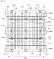
- FIG. 1 is a layout view of an integrated circuit according to example embodiments of the present disclosure
- FIG. 2 is a top view of the integrated circuit according to example embodiments shown up to front-end-of-line (FEOL);
- FOL front-end-of-line
- FIG. 3 is a cross-sectional view taken along line A-A′ of FIG. 2 ;
- FIG. 4 is a cross-sectional view taken along line B-B′ of FIG. 2 ;
- FIGS. 5 A and 5 B are each a cross-sectional view taken along line C-C′ of FIG. 2 ;
- FIG. 6 is a top view of the integrated circuit according to example embodiments shown up to middle-of-line (MOL);
- FIGS. 7 A through 7 B are each a cross-sectional view taken along line D-D′ of FIG. 6 ;
- FIGS. 8 A and 8 B are various views of the source/drain contact of FIG. 6 , cut along the second direction Y;
- FIG. 9 is a view of a wiring layer formed on the top view of FIG. 6 ;
- FIG. 10 A through 10 C are cross-sectional views taken along lines E-E′ and F-F′ of FIG. 9 ;
- FIG. 11 A through 11 B are cross-sectional views taken along line G-G′ of FIG. 9 ;
- FIG. 12 is a top view of an integrated circuit according to example embodiments.
- FIG. 13 is a top view of an integrated circuit according to example embodiments.
- FIG. 14 is a top view of an integrated circuit according to example embodiments.
- FIG. 15 is a top view of an integrated circuit according to example embodiments.
- FIG. 16 is a top view of an integrated circuit according to example embodiments.
- FIG. 17 is a top view of an integrated circuit according to example embodiments.
- FIG. 18 is a top view of an integrated circuit according to example embodiments.
- FIG. 19 is a flowchart illustrating a method of designing an integrated circuit using standard cells according to example embodiments.
- integrated circuits of various example embodiments are provided on a substrate 100 (see FIG. 3 ), for example, a semiconductor substrate.
- An integrated circuit has a layout including various standard cells.
- the standard cells are integrated circuit structures predesigned for repeated use in individual integrated circuit designs.
- Effective integrated circuit design layouts may include various predesigned standard cells and predefined rules for placing the standard cells to improve circuit performance and reduce circuit area.
- An integrated circuit includes one or more standard cells placed in an integrated circuit layout according to predefined rules.
- the standard cells are repeatedly used in integrated circuit design. Therefore, the standard cells may be predesigned according to manufacturing technology and stored in a standard cell library. An integrated circuit designer may search for such standard cells and include the standard cells in an integrated circuit design and may place the standard cells in an integrated circuit layout according to predefined placement rules.
- a standard cell may include various basic circuit devices such as an inverter, AND, NAND, OR, XOR and NOR frequently used in digital circuit designs for electronic devices such as central processing unit (CPU), graphics processing unit (GPU), and system-on-chip (SOC) designs.
- the standard cell may also include other things frequently used in a circuit block, such as a flip-flop and a latch.
- a filler cell may be a designed block of an integrated circuit which is inserted between two adjacent standard cells to conform to integrated circuit design and integrated circuit manufacturing rules.
- the proper design and arrangement of standard cells and filler cells may improve packing density and circuit performance.
- a fin field effect transistor including a fin pattern-shaped channel region
- an integrated circuit according to embodiments may include a tunneling FET, a transistor including a nanowire, a transistor including a nanosheet, and/or a three-dimensional (3D) transistor.
- an integrated circuit according to embodiments of the present disclosure may include a bipolar junction transistor, a lateral double diffused metal oxide semiconductor transistor (LDMOS), or the like.
- FIGS. 1 through 11 B illustrate an integrated circuit according to example embodiments of the present disclosure.
- FIG. 1 is a layout view of an integrated circuit according to example embodiments.
- FIG. 1 may be a layout of a standard cell according to embodiments provided in a cell library.
- the integrated circuit includes at least one cell CELL 1 .
- each cell may be separated from other cells by at least two insulating gates 150 .
- the insulating gates 150 may extend in a second direction Y intersecting a first direction X to separate adjacent cells from each other.
- the integrated circuit includes a first active region 112 , a second active region 114 , an active region separation layer 105 between the first active region 112 and the second active region 114 , at least one gate stack 120 , at least one gate via VB 1 , a plurality of source/drain contacts 170 , 170 - 1 , and 170 - 2 , a plurality of source/drain vias VA 11 - 1 , VA 11 - 2 , VA 11 - 3 , VA 12 , and VA 13 , a first power wiring PWR 1 , a second power wiring PWR 2 , and a plurality of wiring patterns IW, OW 11 , OW 12 , and OW 13 .
- FIG. 2 is a top view of the integrated circuit according to the embodiments shown up to front-end-of-line (FEOL).
- FIG. 3 is a cross-sectional view taken along line A-A′ of FIG. 2 .
- FIG. 4 is a cross-sectional view taken along line B-B′ of FIG. 2 .
- FIGS. 5 A and 5 B are each a cross-sectional view taken along line C-C′ of FIG. 2 .
- FIG. 6 is a top view of the integrated circuit according to the embodiments shown up to middle-of-line (MOL).
- FIGS. 7 A and 7 B are each a cross-sectional view taken along line D-D′ of FIG. 6 .
- FIGS. 8 A and 8 B are various views of the source/drain contact 170 or 170 _ 1 of FIG. 6 , cut along the second direction Y.
- FIG. 9 is a view of a wiring layer formed on the top view of FIG. 6 .
- FIG. 9 illustrates vias connected to a gate contact and source/drain contacts and an M 1 metal layer disposed on the vias.
- the integrated circuit may include at least one standard cell CELL 1 .
- the standard cell CELL 1 may be formed on a substrate 100 .
- the substrate 100 may be a silicon substrate or a silicon-on-insulator (SOI) substrate.
- the substrate 100 may include, but not limited to, silicon germanium, silicon germanium on insulator (SGOI), indium antimonide, lead telluride, indium arsenide, indium phosphide, gallium arsenide, or gallium antimonide.
- the first active region 112 may be defined along the first direction X.
- the first active region 112 may be defined by a deep trench DT.
- the first active region 112 may be a region in which a p-type transistor is formed.
- the first active region 112 may include a well region doped with, e.g., n-type impurities.
- the first active region 112 may include a first lower active region 112 B, a first upper active region 112 U, and first nanosheets 112 NS. Sidewalls of the first lower active region 112 B may be defined by the deep trench DT.
- the first upper active region 112 U may have a fin shape protruding from the first lower active region 112 B. Sidewalls of the first upper active region 112 U may be defined by a trench shallower than the deep trench DT.
- the first nanosheets 112 NS may be spaced apart from the first upper active region 112 U.
- the second active region 114 may be defined along the first direction X.
- the second active region 114 may be defined at a distance from the first active region 112 in the second direction Y.
- the first active region 112 and the second active region 114 may be separated by the deep trench DT.
- the second active region 114 may be a region in which an n-type transistor is formed.
- the second active region 114 may include a well region doped with, e.g., p-type impurities.
- the second active region 114 may include a second lower active region 114 B, a second upper active region 114 U, and second nanosheets that are configured similarly to the first active region 112 .
- Sidewalls of the second lower active region 114 B may be defined by the deep trench DT.
- the second upper active region 114 U may have a fin shape protruding from the second lower active region 114 B.
- Sidewalls of the second upper active region 114 U may be defined by a trench shallower than the deep trench DT.
- the second nanosheets of the second active region 114 may be spaced apart from the second upper active region 114 U.
- the standard cell CELL 1 may include the first active region 112 and the second active region 114 .
- An active region separation layer 105 may be formed on the substrate 100 .
- the active region separation layer 105 may cross between the first active region 112 and the second active region 114 .
- the active region separation layer 105 may extend in the first direction X.
- the active region separation layer 105 may be within and/or fill the deep trench DT that separates the first active region 112 and the second active region 114 .
- a cell separation layer 106 may be formed on the substrate 100 .
- the cell separation layer 106 may be within and/or fill a deep trench DT that is adjacent the first active region 112 and/or the second active region 114 .
- the cell separation layer 106 may extend in the first direction X along a boundary of the standard cell CELL 1 .
- Each of the active region separation layer 105 and the cell separation layer 106 may include an insulating material.
- the active region separation layer 105 and the cell separation layer 106 may include an insulating material that is within and/or fills the deep trench DT defining the first active region 112 and the second active region 114 .
- the active region separation layer 105 may be an insulating material layer disposed between the first active region 112 and the second active region 114 included in one cell. That is, the active region separation layer 105 will be described as an insulating material layer disposed inside a cell.
- the cell separation layer 106 may be an insulating material layer not disposed inside a cell but extending along a cell boundary extending in the first direction X among cell boundaries. That is, the cell separation layer 106 will be described as an insulating material layer disposed along a cell boundary.
- the gate stack 120 and the insulating gates 150 disposed adjacent to each other in the first direction X may be spaced apart by 1 contacted poly pitch (1CPP).
- adjacent gate stacks 120 may be spaced apart by 1 CPP.
- a gate stack 120 and an insulating gate 150 adjacent to each other may be spaced apart by 1 CPP.
- adjacent insulating gates 150 may be spaced apart by 1 CPP.
- a gap between a first gate and a second gate is referred to as a CPP.
- the scope of the present disclosure is not limited thereto, and the gap may also be referred to as another term such as a grid.
- the gate stack 120 and the insulating gates 150 may be disposed over the first active region 112 and the second active region 114 .
- the gate stack 120 and the insulating gates 150 may extend from the first active region 112 to the second active region 114 .
- the gate stack 120 and the insulating gates 150 may cross the active region separation layer 105 .
- a part of the gate stack 120 and a part of each insulating gate 150 may extend on the cell separation layer 106 .
- the integrated circuit may include a plurality of gate stacks 120 and a plurality of insulating gates 150 .
- the gate stacks 120 and the insulating gates 150 may extend along the second direction Y.
- the gate stacks 120 and the insulating gates 150 may be disposed adjacent to each other in the first direction X.
- the gate stack 120 may include a gate electrode 122 , a gate insulating layer 124 , gate spacers 126 , and a gate capping layer 128 . In some cases, the gate stack 120 may not include the gate capping layer 128 .
- the gate spacers 126 may define a gate trench in which the gate insulating layer 124 and the gate electrode 122 may be formed.
- the gate spacers 126 may include, for example, an insulating material.
- the gate insulating layer 124 may be formed along the perimeter of each first nanosheet 112 NS. Although not illustrated, the gate insulating layer 124 may be formed along the perimeter of each second nanosheet of the second active region 114 .
- the gate insulating layer 124 may include at least one of, e.g., silicon oxide and a high-k material.
- the high-k material may be a material having a higher dielectric constant than the silicon oxide.
- the gate electrode 122 may be formed on the gate insulating layer 124 .
- the gate electrode 122 may cover the first nanosheets 112 NS. Although not illustrated, the gate electrode 122 may cover the second nanosheets of the second active region 114 .
- the gate electrode 122 may include at least one of, e.g., metal (including a metal alloy containing two or more metals), metal nitride, metal carbide, metal silicide, and/or a semiconductor material.
- the gate capping layer 128 may be disposed on the gate electrode 122 .
- the gate capping layer 128 may include, for example, an insulating material.
- the insulating gates 150 may divide at least a part of the first active region 112 and at least a part of the second active region 114 .
- the insulating gates 150 may divide the first upper active region 112 U of the first active region 112 .
- the insulating gates 150 divide a part of the first lower active region 112 B of the first active region 112 in the drawings, the present disclosure is not limited thereto.
- the insulating gates 150 may also divide the whole of the first lower active region 112 B.
- the insulating gates 150 may divide the second upper active region 114 U of the second active region 114 and divide a part of the second lower active region 114 B.
- the insulating gates 150 may be formed. Therefore, part of sidewalls of each insulating gate 150 may contact the first active region 112 and the second active region 114 . Part of the sidewalls of each insulating gate 150 may contact a semiconductor material layer included in the first active region 112 and the second active region 114 .
- the insulating gates 150 may cross the active region separation layer 105 .
- the insulating gates 150 may be disposed on the active region separation layer 105 .
- a part of each insulating gate 150 may be recessed into the active region separation layer 105 .
- a part of the active region separation layer 105 may be removed. Therefore, a part of each insulating gate 150 may be recessed into the active region separation layer 105 .
- the gate spacers 126 may be disposed on the sidewalls of each insulating gate 150 .
- the insulating gates 150 may include, for example, an insulating material. Although each insulating gate 150 is illustrated as a single layer, the present disclosure is not limited thereto.
- each insulating gate 150 may be disposed at a boundary of the standard cell CELL 1 extending in the second direction Y to separate adjacent standard cells.
- Each insulating gate 150 may be disposed not only at the boundary of the standard cell but also inside the standard cell. However, each insulating gate 150 will be described below as being disposed at the boundary of the standard cell extending in the second direction Y.
- a semiconductor pattern 130 may be formed between the gate stack 120 and an insulating gate 150 adjacent to each other.
- the semiconductor pattern 130 may be formed by removing a part of an active region 112 or 114 to form a recess and then filling the recess through an epitaxial process.
- the semiconductor pattern 130 may be formed on the first active region 112 .
- the semiconductor pattern 130 may be formed on the second active region 114 . At least a part of the semiconductor pattern 130 may be included in a source/drain region of a transistor.
- the semiconductor pattern 130 formed on the first active region 112 may be doped with impurities of a conductivity type different from that of impurities used to dope the semiconductor pattern 130 formed on the second active region 114 .
- the semiconductor pattern 130 may also be formed between adjacent insulating gates 150 .
- Cell gate cutting patterns 160 may be disposed on the cell separation layer 106 .
- the cell gate cutting patterns 160 may extend in the first direction X.
- the cell gate cutting patterns 160 may extend in the first direction X along the boundaries of the standard cell CELL 1 .
- the gate stack 120 and the insulating gates 150 may be disposed between the cell gate cutting patterns 160 spaced apart in the second direction Y.
- the cell gate cutting patterns 160 may include, for example, an insulating material.
- the cell gate cutting patterns 160 may cut the gate stack 120 and/or the insulating gates 150 at cell boundaries.
- the cell gate cutting patterns 160 may contact the gate stack 120 and/or the insulating gates 150 .
- the cell gate cutting patterns 160 may contact short sides of the gate stack 120 extending in the first direction X and short sides of the insulating gates 150 extending in the first direction X.
- the standard cell CELL 1 may further include the cell gate cutting patterns 160 formed along its boundaries extending in the first direction X.
- the gate insulating layer 124 may not be formed on a sidewall of a cell gate cutting pattern 160 .
- the gate insulating layer 124 may extend along the sidewall of the cell gate cutting pattern 160 . This difference may be based on at what stage the cell gate cutting pattern 160 is formed.
- the gate insulating layer 124 may not be formed on the sidewall of the cell gate cutting pattern 160 as illustrated in FIG. 5 A .
- the gate insulating layer 124 may extend along the sidewall of the cell gate cutting pattern 160 as illustrated in FIG. 5 B .
- the standard cell CELL 1 may share the insulating gates 150 with adjacent cells at common boundaries with the adjacent cells. Although the standard cell CELL 1 is illustrated in FIGS. 1 through 10 C as having a width of 2 CPP for ease of description, it may have a width of at least 1 CPP according to various embodiments.
- the standard cell CELL 1 may further include the first active region 112 and the second active region 114 .
- the gate stack 120 included in the standard cell CELL 1 may intersect the first active region 112 and the second active region 114 .
- the standard cell CELL 1 may include a first p-type transistor and a first n-type transistor.
- the p-type transistor may be formed at an intersection of the gate stack 120 and the first active region 112
- the n-type transistor may be formed at an intersection of the gate stack 120 and the second active region 114 .
- the p-type transistor may include the gate electrode 122 , the first nanosheets 112 NS which are a channel region, and the semiconductor patterns 130 which are source/drain regions.
- the integrated circuit according to the embodiments may include the source/drain contacts 170 , 170 _ 1 , and 170 _ 2 and a gate contact 175 .
- the source/drain contacts 170 , 170 _ 1 , and 170 _ 2 may be disposed on the first active region 112 and the second active region 114 .
- the source/drain contacts 170 , 170 _ 1 , and 170 _ 2 may be connected to the semiconductor patterns 130 formed on the first active region 112 and the second active region 114 .
- the source/drain contacts 170 , 170 _ 1 , and 170 _ 2 may include a normal source/drain contact 170 and extended source/drain contacts 170 _ 1 and 170 _ 2 .
- the normal source/drain contact 170 may entirely overlap the first active region 112 and/or the second active region 114 .
- each of the source/drain contacts 170 _ 1 and 170 _ 2 may extend on the cell separation layer 106 and a cell gate cutting pattern 160 .
- the extended source/drain contacts 170 _ 1 and 170 _ 2 may be connected to the power wirings PWR 1 and PWR 2 (see FIG. 9 ) to be described later.
- the extended source/drain contacts 170 _ 1 and 170 _ 2 may be discontinuously formed.
- the extended source/drain contacts 170 _ 1 and 170 _ 1 may be substantially collinear.
- the gate contact 175 (see FIGS. 10 A and 10 B ) may be formed on the gate stack 120 and is not formed on the insulating gates 150 .
- the gate contact 175 may be connected to the gate stack 120 .
- the gate contact 175 may be electrically connected to the gate electrode 122 of the gate stack 120 .
- the gate contact 175 may be disposed on the first active region 112 and the second active region 114 .
- the gate contact 175 may be formed on the active region separation layer 105 .
- at least one of the gate contacts 175 may be disposed at a position overlapping one of the first active region 112 and the second active region 114 .
- the standard cell CELL 1 may further include at least one normal source/drain contact 170 , the extended source/drain contacts 170 _ 1 and 170 _ 2 , and the gate contact 175 .
- the source/drain contact 170 _ 2 may include a contact barrier layer 170 a and a contact filling layer 170 b .
- the contact filling layer 170 b may be within and/or fill a trench defined by the contact barrier layer 170 a .
- the contact barrier layer 170 a may be formed only between the semiconductor pattern 130 and the contact filling layer 170 b and may not be formed between an interlayer insulating film 190 and the contact filling layer 170 b .
- the contact barrier layer 170 a and the contact filling layer 170 b are illustrated as a single layer instead of separate layers, but the present disclosure is not limited thereto.
- FIGS. 8 A and 8 B illustrate example cross-sections of a source/drain contact 170 , 170 _ 1 , or 170 _ 2 .
- FIGS. 8 A and 8 B are examples of cross-sectional views of the source/drain contact 170 , 170 _ 1 , or 170 _ 2 taken along the second direction Y.
- the gate contact 175 is disposed on the first active region 112 and the second active region 114 , a short margin between the gate contact 175 and each of the source/drain contacts 170 , 170 _ 1 , and 170 _ 2 may be taken into consideration. That is, depending on whether the gate contact 175 is located around the source/drain contacts 170 , 170 _ 1 , and/or 170 _ 2 , the cross-sections of the source/drain contacts 170 , 170 _ 1 , and/or 170 _ 2 may have an L shape (see FIG. 8 A ) or a T shape rotated 180 degrees (see FIG. 8 B ).
- the source/drain contacts 170 , 170 _ 1 , and/or 170 _ 2 may have cross-sections as illustrated in FIGS. 7 A and 7 B .
- the integrated circuit may include source/drain vias VA (e.g., VA 11 - 1 , VA 11 - 2 , VA 11 - 3 , VA 12 , and VA 13 ), the gate via VB 1 , wiring patterns IW and OW (e.g., OW 11 ), and the power wirings PWR 1 and PWR 2 .
- VA source/drain vias VA
- VA 11 - 1 , VA 11 - 2 , VA 11 - 3 , VA 12 , and VA 13 the gate via VB 1
- wiring patterns IW and OW e.g., OW 11
- source/drain vias VA all source/drain vias are referred to as the source/drain vias VA for ease of description, a source/drain via connected to a normal source/drain contact may also be referred to as a normal source/drain via, and a source/drain via connecting an extended source/drain contact and a power wiring may also be referred to as an extended source/drain via.
- the standard cell CELL 1 may include the source/drain vias VA, the gate via VB 1 , the wiring patterns IW and OW 11 , and the power wirings PWR 1 and PWR 2 .
- the gate via VB 1 may be formed on the gate contact 175 .
- the gate via VB 1 may connect the gate contact 175 to an input wiring pattern IW.
- the source/drain vias VA may be formed on the source/drain contacts 170 , 170 _ 1 , and 170 _ 2 .
- the source/drain vias VA may be at least partially connected to the source/drain contacts 170 , 170 _ 1 , and 170 _ 2 .
- the source/drain vias VA may include a normal via VA 11 (e.g., VA 11 - 1 ) connecting the normal source/drain contact 170 and an output wiring pattern OW (e.g., OW 11 ) and power wiring vias VA 12 and VA 13 connecting the extended source/drain contacts 170 _ 1 and 170 _ 2 and the power wirings PWR 1 and PWR 2 .
- a normal via VA 11 e.g., VA 11 - 1
- OW e.g., OW 11
- the wiring patterns IW and OW 11 and the power wirings PWR 1 and PWR 2 may extend in the first direction X.
- the power wirings PWR 1 and PWR 2 may include the upper power wiring PWR 1 to which a first voltage is supplied and the lower power wiring PWR 2 to which a second voltage is supplied.
- the upper power wiring PWR 1 may supply power to the p-type transistor, and the lower power wiring PWR 2 may supply power to the n-type transistor.
- a structure connecting the gate contact 175 to the input wiring pattern IW and structures connecting the source/drain contacts 170 , 170 _ 1 and 170 _ 2 to the output wiring pattern OW 11 and the power wirings PWR 1 and PWR 2 may not be the structures illustrated in FIGS. 10 A and 11 A .
- a middle contact 176 may be further interposed between the source/drain vias VA and the source/drain contacts 170 , 170 _ 1 , and 170 _ 2 .
- the middle contact 176 may be further interposed between the gate via VB 1 and the gate contact 175 .
- the input wiring pattern IW and the gate via VB 1 are integrated with each other in the drawings, the present disclosure is not limited thereto.
- the input wiring pattern IW and the gate via VB 1 may also be separated by a barrier layer.
- the source/drain contacts 170 , 170 _ 1 , and 170 _ 2 may be connected to the output wiring pattern OW 11 and the power wirings PWR 1 and PWR 2 without the source/drain vias VA.
- the gate contact 175 may be connected to the input wiring pattern IW without the gate via VB 1 .
- FIG. 12 is a top view of an integrated circuit according to example embodiments.
- a redundant description of the same elements and features as those described above using FIGS. 1 through 11 B will be given briefly or omitted.
- FIGS. 12 through 14 are top views of integrated circuits according to example embodiments. For ease of description, an input wiring and an output wiring will be referred to as such, but may also be referred to as connection wirings between cells.
- an input wiring IW may be connected to a gate stack 120 extending in the second direction Y.
- the input wiring IW may overlap a gate via VB 11 , VB 12 , or VB 13 in a third direction Z.
- At least a part of a gate via may overlap an active region separation layer 105 (RB region).
- the gate via VB 12 may be disposed on the gate stack 120 intersecting the active region separation layer 105
- the gate via VB 11 may be disposed on the gate stack 120 extending over a part of the active region separation layer 105 and a part of a first active region 112 .
- the gate via VB 13 may be disposed on the gate stack 120 extending over a part of the active region separation layer 105 and a part of a second active region 114 .
- a gate via VB may also be disposed on the gate stack 120 in a part of an RA region excluding the RB region (illustrated as regions RA 1 and RA 2 in FIG. 12 ).
- a gate via may be disposed on the gate stack 120 intersecting the first active region 112 extending in the first direction X, or a gate via may be disposed on the gate stack 120 intersecting the second active region 114 .
- an output wiring OW is disposed at the same level as the input wiring IW and extends in the same first direction X as the input wiring IW but does not overlap the input wiring IW. That is, the input wiring IW and the output wiring OW are staggered.
- the output wiring OW may be disposed on a source/drain via VA overlapping, in the third direction Z, a source/drain contact 170 on an upper surface of the first active region 112 according to embodiments.
- the output wiring OW may be disposed on a source/drain via VA overlapping, in the third direction Z, the source/drain contact 170 on the second active region 114 between the input wiring IW and a second power wiring PWR 2 according to embodiments.
- a first power wiring PWR 1 , the second power wiring PWR 2 , the input wiring IW, and the output wiring OW may be disposed at the same level M 1 .
- the output wiring OW may intersect a part of the normal source/drain contact 170 excluding the normal source/drain contact 170 intersecting the input wiring IW in the second direction Y. That is, in the standard cell, the output wiring OW may not be routed to a wiring pattern at a higher level than the input wiring IW by using the normal source/drain contact 170 as an output terminal, thereby further improving integration density.
- an integrated circuit may include a first standard cell CELL 1 , a second standard cell CELL 2 , and a third standard cell CELL 3 .
- the integrated circuit includes three buffers connected in series.
- Each of the first through third standard cells CELL 1 through CELL 3 may include a p-type transistor formed on a first active region 112 and an n-type transistor formed on a second active region 114 .
- Each standard cell may have a width of 2 CPP.
- Extended source/drain contacts 170 _ 1 of the first through third standard cells CELL 1 , CELL 2 , and CELL 3 may be connected to a first power wiring PWR 1 through source/drain vias VA 12 , VA 22 , and VA 32 , and extended source/drain contacts 170 _ 2 are connected to a second power wiring PWR 2 through source/drain vias VA 13 , VA 23 , and VA 33 .
- An input wiring IW 1 may be connected to a gate stack 120 on an active region separation layer 105 of the first standard cell CELL 1 through a gate via VB 2 .
- a normal source/drain contact 170 of the first standard cell CELL 1 may be connected to a first intermediate wiring CW 1 extending in the first direction X through a source/drain via VA 1 .
- the first intermediate wiring CW 1 may be connected to a gate stack 120 of the second standard cell CELL 2 through a gate via VB 1 .
- a normal source/drain contact 170 of the second standard cell CELL 2 may be connected to a second intermediate wiring CW 2 extending in the first direction X through a source/drain via VA 2 .
- the second intermediate wiring CW 2 may be connected to a gate stack 120 of the third standard cell CELL 3 through a gate via VB 3 .
- a normal source/drain contact 170 of the third standard cell CELL 3 may be connected to an output wiring OW extending in the first direction X through a source/drain via VA 3 .
- the first power wiring PWR 1 , the second power wiring PWR 2 , the input wiring IW, the intermediate wirings CW 1 and CW 2 , and the output wiring OW are all disposed at the same M 1 level. However, the input wiring IW 1 , the intermediate wirings CW 1 and CW 2 , and the output wiring OW are staggered not to overlap each other in one standard cell.
- FIG. 14 is a top view of an integrated circuit according to embodiments.
- a standard cell may be designed to include at least three power wirings and at least four active regions.
- the integrated circuit according to the embodiments may include a first standard cell CELL 1 having a width of 2 CPP and a second standard cell CELL 2 having a width of 3 CPP.
- the integrated circuit may include a first power wiring PWR 1 , a second power wiring PWR 2 , and a third power wiring PWR 1 .
- the two power wirings PWR 1 included in FIG. 14 will be referred to as the first power wiring PWR 1 (bottom) and the third power wiring PWR 1 (top), respectively.
- the same power supply voltage may be applied to the first power wiring PWR 1 and the third power wiring PWR 1 .
- the integrated circuit may include a first active region 112 and a second active region 114 between the first power wiring PWR 1 and the second power wiring PWR 2 extending in the first direction X and spaced apart by a predetermined distance in the second direction Y.
- the integrated circuit may include a third active region 114 and a fourth active region 112 between the second power wiring PWR 2 and the third power wiring PWR 1 extending in the first direction X and spaced apart by a predetermined distance in the second direction Y.
- the two active regions 112 included in FIG. 14 will be referred to as the first active region 112 (bottom) and the fourth active region 112 (top), respectively.
- the active region separation layer 105 may be respectively between the first active region 112 , the second active region 114 , the third active region 114 , and the fourth active region 112 .
- the integrated circuit includes insulating gates 150 and gate stacks 120 spaced apart from each other by 1 CPP.
- the first standard cell CELL 1 may include two insulating gates 150 and one gate stack 120 .
- the second standard cell CELL 2 may include two insulating gates 150 and two gate stacks 120 .
- the integrated circuit includes a plurality of source/drain contacts 170 , 170 _ 1 , and 170 _ 2 .
- the first standard cell CELL 1 includes extended source/drain contacts 170 _ 1 and 170 _ 2 between one insulating gate 150 and the gate stack 120 .
- the extended source/drain contacts 170 _ 1 and 170 _ 2 may intersect and be connected to the first power wiring PWR 1 (bottom), the second power wiring PWR 2 and the third power wiring PWR 1 (top) through source/drain vias. VA 11 through VA 14 , respectively.
- the first standard cell CELL 1 includes a normal source/drain contact 170 between another insulating gate 150 and the gate stack 120 .
- the normal source/drain contact 170 may intersect and be connected to a first output wiring OW 1 through a source/drain via VA 15 .
- the two gate stacks 120 included in the second standard cell CELL 2 will be referred to as a first gate stack 120 (left) and a second gate stack 120 (right), respectively.
- the gate stack 120 of the first standard cell CELL 1 and the first gate stack 120 and the second gate stack 120 of the second standard cell CELL 2 may intersect an input wiring IW and be connected to the input wiring IW through gate vias VB 1 through VB 3 .
- the second standard cell CELL 2 includes extended source/drain contacts 170 _ 1 and 170 _ 2 between one insulating gate 150 and the first gate stack 120 and extended source/drain contacts 170 _ 1 and 170 _ 2 between the second gate stack 120 and another insulating gate 150 .
- the extended source/drain contacts 170 _ 1 and 170 _ 2 may intersect and be connected to the first power wiring PWR 1 (bottom), the second power wiring PWR 2 , and the third power wiring PWR 1 (top) through source/drain vias VA 21 through VA 24 and VA 31 through VA 34 , respectively.
- the second standard cell CELL 2 includes a normal source/drain contact 170 between the first gate stack 120 and the second gate stack 120 .
- the normal source/drain contact 170 may intersect and be connected to a second output wiring OW 2 through a source/drain via VA 16 .
- the first output wiring OW 1 and the second output wiring OW 2 may be spaced apart from the input wiring IW in the second direction Y so as not to overlap the input wiring IW in their respective standard cells.
- the first output wiring OW 1 and the second output wiring OW 2 are illustrated as separate wiring patterns.
- the first output wiring OW 1 and the second output wiring OW 2 may also be connected to form the same wiring pattern according to another standard cell arrangement embodiment.
- FIG. 15 is a top view of an integrated circuit according to example embodiments.
- FIG. 16 is a top view of an integrated circuit according to example embodiments.
- the embodiments of FIG. 15 show a single-height standard cell disposed between two power wirings, and the embodiments of FIG. 16 show a multi-height standard cell disposed between three or more power wirings.
- the integrated circuit may include an additional power wiring to stabilize power supplied to each standard cell. That is, because a plurality of standard cells are disposed, a power wiring may be additionally disposed to supplement power supply.
- a standard cell having a width of 4 CPP may include a first additional power wiring PW 1 .
- the same first power supply voltage may be applied to the first additional power wiring PW 1 and a first power wiring PWR 1 .
- the first additional power wiring PW 1 may intersect first extended source/drain contacts 170 _ 1 and be connected to the first extended source/drain contacts 170 _ 1 through source/drain vias VA 23 and VA 13 .
- the standard cell may also include a second additional power wiring PW 2 .
- the same second power supply voltage may be applied to the second additional power wiring PW 2 and a second power wiring PWR 2 .
- the second additional power wiring PW 2 may intersect second extended source/drain contacts 170 _ 2 and be connected to the second extended source/drain contacts 170 _ 2 through source/drain vias VA 24 and VA 14 .
- the integrated circuit may include a first additional power wiring PW 1 or a second additional power wiring PW 2 .
- the first additional power wiring PW 1 may be disposed between a third power wiring PWR 1 (top) and a second power wiring PWR 2
- the second additional power wiring PW 2 may be disposed between the second power wiring PWR 2 and a first power wiring PWR 1 (bottom).
- FIG. 17 is a top view of an integrated circuit according to example embodiments.
- the integrated circuit may include first through fourth single-height standard cells CELL 1 through CELL 4 branching from a multi-height standard cell CELL X and connected to the multi-height standard cell CELL X.
- the multi-height standard cell CELL X may be any one standard cell set in a standard cell library or may be a filler cell.
- the first through fourth standard cells CELL 1 through CELL 4 may be identical or different standard cells or may be complementary standard cells.
- CELL X and/or CELL 1 through CELL 4 may be configured using example cell structures described herein.
- the multi-height standard cell CELL X may be connected to the first through fourth single-height standard cells CELL 1 through CELL 4 .
- the multi-height standard cell CELL X may include two insulating gates 150 and at least one normal source/drain contact 170 extending in the second direction Y between an uppermost power wiring and a lowermost power wiring.
- the multi-height standard cell CELL X may include extended source/drain contacts 170 _ 1 and 170 _ 2 extending in the second direction Y between a plurality of power wirings and spaced apart by a predetermined distance.
- the multi-height standard cell CELL X When the multi-height standard cell CELL X is a standard cell, it may further include at least one gate stack 120 between the insulating gates 150 spaced apart in the first direction X. In this case, an input wiring IW 1 may intersect and be connected to the gate stack 120 . Branching intermediate wirings CW 1 through CW 4 may intersect the normal source/drain contact 170 and may be used as input wirings of the adjacent single-height standard cells CELL 1 through CELL 4 .
- the multi-height standard cell CELL X When the multi-height standard cell CELL X is a filler cell, it may include two or more insulating gates 150 and a filler source/drain contact.
- the filler source/drain contact may be a normal source/drain contact 170 .
- the input wiring IW 1 may intersect and be connected to the filler source/drain contact 170 .
- the branching intermediate wirings CW 1 through CW 4 may intersect the filler source/drain contact 170 and may be used as the input wirings of the adjacent single-height standard cells CELL 1 through CELL 4 .
- the intermediate wirings CW 1 through CW 4 extending from the multi-height standard cell CELL X may intersect and be connected to the gate stacks 120 of the single-height standard cells CELL 1 through CELL 4 through gate vias VB, respectively.
- At least one normal source/drain contact 170 of each of the single-height standard cells CELL 1 through CELL 4 may be connected to an output wiring OW 1 , OW 2 , OW 3 or OW 4 extending in the first direction X through a source/drain via VA.
- a power wiring, an input wiring, an intermediate wiring, and an output wiring between a standard cell and a standard cell may be disposed at the same level M 1 , thereby improving placement and routing (PnR) density.
- FIG. 18 is a top view of an integrated circuit according to example embodiments.
- the integrated circuit may include a plurality of standard cells and a filler cell.
- the illustrated embodiments four single-height standard cells (CELL 1 through CELL 5 ) and one multi-height filler cell are illustrated.
- CELL 1 through CELL 5 single-height standard cells
- multi-height filler cell multi-height filler cell
- the filler cell may be disposed between adjacent standard cells when input and output wirings in each standard cell are complicated.
- An input wiring, an intermediate wiring, and an output wiring are all wiring patterns extending in the first direction X and should be placed not to overlap each other in the first direction X within one standard cell.
- a filler cell may be used.
- the filler cell and/or CELL 1 through CELL 5 may be configured using example cell structures described herein.
- the standard cell CELL 1 may transmit an output signal to the adjacent standard cells CELL 2 through CELL 4 by using a normal source/drain contact 170 of the filler cell as an output terminal.
- an output wiring CW 1 of the standard cell CELL 1 may be connected to the normal source/drain contact 170 of the filler cell through a source/drain via VA
- input wirings CW 2 through CW 4 of the adjacent standard cells CELL 2 through CELL 4 may be connected to the normal source/drain contact 170 of the filler cell through source/drain vias VA.
- FIG. 19 is a flowchart illustrating a method of designing an integrated circuit using standard cells according to example embodiments.
- a process design for an integrated circuit required by a user is set (operation S 10 ).
- standard cells required for the set process design are selected from a pre-stored standard cell library (operation S 20 ) and combined according to the process (operation S 30 ).
- the standard cell library may store layouts of a plurality of standard cells and information about the standard cells.
- the information about the standard cells may include functions, characteristics, and requirements of the standard cells.
- the standard cells When the standard cells are combined, they may be selected from the standard cell library in consideration of placement according to an operation sequence, the routing relationship between input/output wirings for transmitting signals, operation timing, etc.
- the finally selected standard cells may be taped out to a final layout of the integrated circuit by combining all of operation timing, signal wirings, etc. (operation S 40 ).
Landscapes
- Design And Manufacture Of Integrated Circuits (AREA)
- Engineering & Computer Science (AREA)
- General Engineering & Computer Science (AREA)
Abstract
Description
Claims (20)
Applications Claiming Priority (4)
| Application Number | Priority Date | Filing Date | Title |
|---|---|---|---|
| KR10-2019-0156480 | 2019-11-29 | ||
| KR20190156480 | 2019-11-29 | ||
| KR10-2020-0053914 | 2020-05-06 | ||
| KR1020200053914A KR102868418B1 (en) | 2019-11-29 | 2020-05-06 | Integrated Circuit including integrated standard cell structure |
Publications (2)
| Publication Number | Publication Date |
|---|---|
| US20210167090A1 US20210167090A1 (en) | 2021-06-03 |
| US11810920B2 true US11810920B2 (en) | 2023-11-07 |
Family
ID=76043046
Family Applications (1)
| Application Number | Title | Priority Date | Filing Date |
|---|---|---|---|
| US17/027,211 Active 2041-09-07 US11810920B2 (en) | 2019-11-29 | 2020-09-21 | Integrated circuits including integrated standard cell structure |
Country Status (2)
| Country | Link |
|---|---|
| US (1) | US11810920B2 (en) |
| CN (1) | CN112885829B (en) |
Cited By (1)
| Publication number | Priority date | Publication date | Assignee | Title |
|---|---|---|---|---|
| US12356726B2 (en) * | 2019-10-02 | 2025-07-08 | Samsung Electronics Co., Ltd. | Semiconductor devices and methods of manufacturing the same |
Families Citing this family (5)
| Publication number | Priority date | Publication date | Assignee | Title |
|---|---|---|---|---|
| KR20230016759A (en) * | 2021-07-26 | 2023-02-03 | 삼성전자주식회사 | Semiconductor device |
| US12183431B2 (en) | 2022-05-07 | 2024-12-31 | Changxin Memory Technologies, Inc. | Semiconductor structure and chip |
| CN114864538A (en) * | 2022-05-07 | 2022-08-05 | 长鑫存储技术有限公司 | Semiconductor structure and chip |
| CN117727751B (en) * | 2022-09-19 | 2026-01-27 | 华为技术有限公司 | Standard cell, integrated circuit, standard cell library, and electronic device |
| KR20240166065A (en) * | 2023-05-16 | 2024-11-26 | 삼성디스플레이 주식회사 | Driver and display device |
Citations (11)
| Publication number | Priority date | Publication date | Assignee | Title |
|---|---|---|---|---|
| US20170154848A1 (en) | 2015-11-30 | 2017-06-01 | Taiwan Semiconductor Manufacturing Co., Ltd. | Standard-cell layout structure with horn power and smart metal cut |
| US9734276B2 (en) | 2014-10-22 | 2017-08-15 | Samsung Electronics Co., Ltd. | Integrated circuit and method of designing layout of the same |
| KR20170099338A (en) | 2016-02-23 | 2017-08-31 | 삼성전자주식회사 | Semiconductor device |
| US9768111B2 (en) | 2013-03-05 | 2017-09-19 | Oracle International Corporation | Mitigating electromigration effects using parallel pillars |
| US20180342468A1 (en) | 2017-05-23 | 2018-11-29 | Board Of Regents, The University Of Texas System | Defense Techniques for Split Manufacturing |
| US20180365368A1 (en) | 2017-06-14 | 2018-12-20 | Samsung Electronics Co., Ltd. | Integrated circuit including standard cells overlapping each other and method of generating layout of the integrated circuit |
| US10248752B2 (en) | 2016-01-11 | 2019-04-02 | Samsung Electronics Co., Ltd. | Method for routing between pins of semiconductor device and design system therewith |
| US10354947B2 (en) | 2017-02-06 | 2019-07-16 | Samsung Electronics Co., Ltd. | Integrated circuit including standard cell |
| US20210057281A1 (en) * | 2019-08-22 | 2021-02-25 | Taiwan Semiconductor Manufacturing Co., Ltd. | Ic including standard cells and sram cells |
| US20210098466A1 (en) * | 2019-10-01 | 2021-04-01 | Taiwan Semiconductor Manufacturing Co., Ltd. | Semiconductor structure with dielectric fin in memory cell and method for forming the same |
| KR20210041737A (en) | 2019-10-08 | 2021-04-16 | 삼성전자주식회사 | Semiconductor device, layout design method for the same and method for fabricating the same |
Family Cites Families (7)
| Publication number | Priority date | Publication date | Assignee | Title |
|---|---|---|---|---|
| JP6281570B2 (en) * | 2013-08-23 | 2018-02-21 | 株式会社ソシオネクスト | Semiconductor integrated circuit device |
| KR102415952B1 (en) * | 2015-07-30 | 2022-07-05 | 삼성전자주식회사 | Method of design layout of semiconductor device, and method for manufacturing semiconductor device using the same |
| KR102315275B1 (en) * | 2015-10-15 | 2021-10-20 | 삼성전자 주식회사 | Integrated circuit device and method of manufacturing the same |
| KR102497218B1 (en) * | 2016-04-29 | 2023-02-07 | 삼성전자 주식회사 | Integrated circuit including complex logic cell |
| JP6966686B2 (en) * | 2016-10-21 | 2021-11-17 | 株式会社ソシオネクスト | Semiconductor device |
| US10741543B2 (en) * | 2017-11-30 | 2020-08-11 | Taiwan Semiconductor Manufacturing Co., Ltd. | Device including integrated electrostatic discharge protection component |
| KR102419646B1 (en) * | 2017-12-22 | 2022-07-11 | 삼성전자주식회사 | Integrated circuit having cross couple construct and semiconductor including the same |
-
2020
- 2020-09-21 US US17/027,211 patent/US11810920B2/en active Active
- 2020-11-11 CN CN202011256628.XA patent/CN112885829B/en active Active
Patent Citations (12)
| Publication number | Priority date | Publication date | Assignee | Title |
|---|---|---|---|---|
| US9768111B2 (en) | 2013-03-05 | 2017-09-19 | Oracle International Corporation | Mitigating electromigration effects using parallel pillars |
| US9734276B2 (en) | 2014-10-22 | 2017-08-15 | Samsung Electronics Co., Ltd. | Integrated circuit and method of designing layout of the same |
| US20170154848A1 (en) | 2015-11-30 | 2017-06-01 | Taiwan Semiconductor Manufacturing Co., Ltd. | Standard-cell layout structure with horn power and smart metal cut |
| US10248752B2 (en) | 2016-01-11 | 2019-04-02 | Samsung Electronics Co., Ltd. | Method for routing between pins of semiconductor device and design system therewith |
| KR20170099338A (en) | 2016-02-23 | 2017-08-31 | 삼성전자주식회사 | Semiconductor device |
| US10354947B2 (en) | 2017-02-06 | 2019-07-16 | Samsung Electronics Co., Ltd. | Integrated circuit including standard cell |
| US20190287891A1 (en) | 2017-02-06 | 2019-09-19 | Samsung Electronics Co., Ltd. | Integrated circuit including standard cell |
| US20180342468A1 (en) | 2017-05-23 | 2018-11-29 | Board Of Regents, The University Of Texas System | Defense Techniques for Split Manufacturing |
| US20180365368A1 (en) | 2017-06-14 | 2018-12-20 | Samsung Electronics Co., Ltd. | Integrated circuit including standard cells overlapping each other and method of generating layout of the integrated circuit |
| US20210057281A1 (en) * | 2019-08-22 | 2021-02-25 | Taiwan Semiconductor Manufacturing Co., Ltd. | Ic including standard cells and sram cells |
| US20210098466A1 (en) * | 2019-10-01 | 2021-04-01 | Taiwan Semiconductor Manufacturing Co., Ltd. | Semiconductor structure with dielectric fin in memory cell and method for forming the same |
| KR20210041737A (en) | 2019-10-08 | 2021-04-16 | 삼성전자주식회사 | Semiconductor device, layout design method for the same and method for fabricating the same |
Cited By (1)
| Publication number | Priority date | Publication date | Assignee | Title |
|---|---|---|---|---|
| US12356726B2 (en) * | 2019-10-02 | 2025-07-08 | Samsung Electronics Co., Ltd. | Semiconductor devices and methods of manufacturing the same |
Also Published As
| Publication number | Publication date |
|---|---|
| CN112885829A (en) | 2021-06-01 |
| CN112885829B (en) | 2024-12-03 |
| US20210167090A1 (en) | 2021-06-03 |
Similar Documents
| Publication | Publication Date | Title |
|---|---|---|
| US11695002B2 (en) | Integrated circuit including integrated standard cell structure | |
| US11810920B2 (en) | Integrated circuits including integrated standard cell structure | |
| US12464821B2 (en) | Integrated circuit including integrated standard cell structure | |
| US12310103B2 (en) | Semiconductor integrated circuit device having standard cells including three dimensional transistors | |
| US12119339B2 (en) | Semiconductor integrated circuit device | |
| KR102201103B1 (en) | Semiconductor device | |
| US10163879B2 (en) | Semiconductor device having jumper pattern | |
| US20210320065A1 (en) | Semiconductor integrated circuit device | |
| US11948932B2 (en) | Integrated circuit including standard cell and filler cell | |
| KR102843610B1 (en) | Semiconductor device, layout design method for the same and method for fabricating the same | |
| CN106252328A (en) | Semiconductor device | |
| KR20170038611A (en) | Semiconductor device | |
| US12218121B2 (en) | Semiconductor devices having improved layout designs, and methods of designing and fabricating the same | |
| US11764201B2 (en) | Integrated circuit including standard cells | |
| TWI859364B (en) | Integrated circuits including integrated standard cell structure | |
| KR102891200B1 (en) | Integrated Circuitry including Standard Cell |
Legal Events
| Date | Code | Title | Description |
|---|---|---|---|
| FEPP | Fee payment procedure |
Free format text: ENTITY STATUS SET TO UNDISCOUNTED (ORIGINAL EVENT CODE: BIG.); ENTITY STATUS OF PATENT OWNER: LARGE ENTITY |
|
| AS | Assignment |
Owner name: SAMSUNG ELECTRONICS CO., LTD., KOREA, REPUBLIC OF Free format text: ASSIGNMENT OF ASSIGNORS INTEREST;ASSIGNORS:YU, JI SU;PARK, JAE-HO;BAEK, SANGHOON;AND OTHERS;SIGNING DATES FROM 20200914 TO 20200916;REEL/FRAME:053889/0034 |
|
| AS | Assignment |
Owner name: SAMSUNG ELECTRONICS CO., LTD., KOREA, REPUBLIC OF Free format text: CORRECTIVE ASSIGNMENT TO CORRECT THE CONVEYING PARTY DATA OF INVENTOR "HYEON GYU" PREVIOUSLY RECORDED ON REEL 053889 FRAME 0034. ASSIGNOR(S) HEREBY CONFIRMS THE CONVEYING PARTY DATA OF INVENTOR READ --HYEON GYU YOU--;ASSIGNORS:YU, JI SU;PARK, JAE-HO;BAEK, SANGHOON;AND OTHERS;SIGNING DATES FROM 20200914 TO 20200916;REEL/FRAME:053918/0085 |
|
| STPP | Information on status: patent application and granting procedure in general |
Free format text: APPLICATION DISPATCHED FROM PREEXAM, NOT YET DOCKETED |
|
| STPP | Information on status: patent application and granting procedure in general |
Free format text: DOCKETED NEW CASE - READY FOR EXAMINATION |
|
| STPP | Information on status: patent application and granting procedure in general |
Free format text: NON FINAL ACTION MAILED |
|
| STPP | Information on status: patent application and granting procedure in general |
Free format text: RESPONSE TO NON-FINAL OFFICE ACTION ENTERED AND FORWARDED TO EXAMINER |
|
| STPP | Information on status: patent application and granting procedure in general |
Free format text: NON FINAL ACTION MAILED |
|
| STPP | Information on status: patent application and granting procedure in general |
Free format text: NOTICE OF ALLOWANCE MAILED -- APPLICATION RECEIVED IN OFFICE OF PUBLICATIONS |
|
| STPP | Information on status: patent application and granting procedure in general |
Free format text: PUBLICATIONS -- ISSUE FEE PAYMENT VERIFIED |
|
| STCF | Information on status: patent grant |
Free format text: PATENTED CASE |