US11807232B2 - Method and apparatus for tracking an object and a recording medium storing a program to execute the method - Google Patents
Method and apparatus for tracking an object and a recording medium storing a program to execute the method Download PDFInfo
- Publication number
- US11807232B2 US11807232B2 US17/463,681 US202117463681A US11807232B2 US 11807232 B2 US11807232 B2 US 11807232B2 US 202117463681 A US202117463681 A US 202117463681A US 11807232 B2 US11807232 B2 US 11807232B2
- Authority
- US
- United States
- Prior art keywords
- velocity
- history
- heading
- heading angle
- track
- Prior art date
- Legal status (The legal status is an assumption and is not a legal conclusion. Google has not performed a legal analysis and makes no representation as to the accuracy of the status listed.)
- Active, expires
Links
Images


Classifications
-
- B—PERFORMING OPERATIONS; TRANSPORTING
- B60—VEHICLES IN GENERAL
- B60W—CONJOINT CONTROL OF VEHICLE SUB-UNITS OF DIFFERENT TYPE OR DIFFERENT FUNCTION; CONTROL SYSTEMS SPECIALLY ADAPTED FOR HYBRID VEHICLES; ROAD VEHICLE DRIVE CONTROL SYSTEMS FOR PURPOSES NOT RELATED TO THE CONTROL OF A PARTICULAR SUB-UNIT
- B60W30/00—Purposes of road vehicle drive control systems not related to the control of a particular sub-unit, e.g. of systems using conjoint control of vehicle sub-units
- B60W30/08—Active safety systems predicting or avoiding probable or impending collision or attempting to minimise its consequences
- B60W30/095—Predicting travel path or likelihood of collision
-
- G—PHYSICS
- G06—COMPUTING OR CALCULATING; COUNTING
- G06T—IMAGE DATA PROCESSING OR GENERATION, IN GENERAL
- G06T7/00—Image analysis
- G06T7/20—Analysis of motion
-
- G—PHYSICS
- G01—MEASURING; TESTING
- G01S—RADIO DIRECTION-FINDING; RADIO NAVIGATION; DETERMINING DISTANCE OR VELOCITY BY USE OF RADIO WAVES; LOCATING OR PRESENCE-DETECTING BY USE OF THE REFLECTION OR RERADIATION OF RADIO WAVES; ANALOGOUS ARRANGEMENTS USING OTHER WAVES
- G01S7/00—Details of systems according to groups G01S13/00, G01S15/00, G01S17/00
- G01S7/48—Details of systems according to groups G01S13/00, G01S15/00, G01S17/00 of systems according to group G01S17/00
- G01S7/497—Means for monitoring or calibrating
-
- G—PHYSICS
- G01—MEASURING; TESTING
- G01S—RADIO DIRECTION-FINDING; RADIO NAVIGATION; DETERMINING DISTANCE OR VELOCITY BY USE OF RADIO WAVES; LOCATING OR PRESENCE-DETECTING BY USE OF THE REFLECTION OR RERADIATION OF RADIO WAVES; ANALOGOUS ARRANGEMENTS USING OTHER WAVES
- G01S17/00—Systems using the reflection or reradiation of electromagnetic waves other than radio waves, e.g. lidar systems
- G01S17/02—Systems using the reflection of electromagnetic waves other than radio waves
- G01S17/06—Systems determining position data of a target
- G01S17/08—Systems determining position data of a target for measuring distance only
- G01S17/10—Systems determining position data of a target for measuring distance only using transmission of interrupted, pulse-modulated waves
-
- B—PERFORMING OPERATIONS; TRANSPORTING
- B60—VEHICLES IN GENERAL
- B60W—CONJOINT CONTROL OF VEHICLE SUB-UNITS OF DIFFERENT TYPE OR DIFFERENT FUNCTION; CONTROL SYSTEMS SPECIALLY ADAPTED FOR HYBRID VEHICLES; ROAD VEHICLE DRIVE CONTROL SYSTEMS FOR PURPOSES NOT RELATED TO THE CONTROL OF A PARTICULAR SUB-UNIT
- B60W40/00—Estimation or calculation of non-directly measurable driving parameters for road vehicle drive control systems not related to the control of a particular sub unit, e.g. by using mathematical models
- B60W40/02—Estimation or calculation of non-directly measurable driving parameters for road vehicle drive control systems not related to the control of a particular sub unit, e.g. by using mathematical models related to ambient conditions
- B60W40/04—Traffic conditions
-
- G—PHYSICS
- G01—MEASURING; TESTING
- G01S—RADIO DIRECTION-FINDING; RADIO NAVIGATION; DETERMINING DISTANCE OR VELOCITY BY USE OF RADIO WAVES; LOCATING OR PRESENCE-DETECTING BY USE OF THE REFLECTION OR RERADIATION OF RADIO WAVES; ANALOGOUS ARRANGEMENTS USING OTHER WAVES
- G01S17/00—Systems using the reflection or reradiation of electromagnetic waves other than radio waves, e.g. lidar systems
- G01S17/02—Systems using the reflection of electromagnetic waves other than radio waves
- G01S17/50—Systems of measurement based on relative movement of target
- G01S17/58—Velocity or trajectory determination systems; Sense-of-movement determination systems
-
- G—PHYSICS
- G01—MEASURING; TESTING
- G01S—RADIO DIRECTION-FINDING; RADIO NAVIGATION; DETERMINING DISTANCE OR VELOCITY BY USE OF RADIO WAVES; LOCATING OR PRESENCE-DETECTING BY USE OF THE REFLECTION OR RERADIATION OF RADIO WAVES; ANALOGOUS ARRANGEMENTS USING OTHER WAVES
- G01S17/00—Systems using the reflection or reradiation of electromagnetic waves other than radio waves, e.g. lidar systems
- G01S17/66—Tracking systems using electromagnetic waves other than radio waves
-
- G—PHYSICS
- G01—MEASURING; TESTING
- G01S—RADIO DIRECTION-FINDING; RADIO NAVIGATION; DETERMINING DISTANCE OR VELOCITY BY USE OF RADIO WAVES; LOCATING OR PRESENCE-DETECTING BY USE OF THE REFLECTION OR RERADIATION OF RADIO WAVES; ANALOGOUS ARRANGEMENTS USING OTHER WAVES
- G01S17/00—Systems using the reflection or reradiation of electromagnetic waves other than radio waves, e.g. lidar systems
- G01S17/88—Lidar systems specially adapted for specific applications
- G01S17/89—Lidar systems specially adapted for specific applications for mapping or imaging
-
- G—PHYSICS
- G01—MEASURING; TESTING
- G01S—RADIO DIRECTION-FINDING; RADIO NAVIGATION; DETERMINING DISTANCE OR VELOCITY BY USE OF RADIO WAVES; LOCATING OR PRESENCE-DETECTING BY USE OF THE REFLECTION OR RERADIATION OF RADIO WAVES; ANALOGOUS ARRANGEMENTS USING OTHER WAVES
- G01S17/00—Systems using the reflection or reradiation of electromagnetic waves other than radio waves, e.g. lidar systems
- G01S17/88—Lidar systems specially adapted for specific applications
- G01S17/93—Lidar systems specially adapted for specific applications for anti-collision purposes
- G01S17/931—Lidar systems specially adapted for specific applications for anti-collision purposes of land vehicles
-
- G—PHYSICS
- G01—MEASURING; TESTING
- G01S—RADIO DIRECTION-FINDING; RADIO NAVIGATION; DETERMINING DISTANCE OR VELOCITY BY USE OF RADIO WAVES; LOCATING OR PRESENCE-DETECTING BY USE OF THE REFLECTION OR RERADIATION OF RADIO WAVES; ANALOGOUS ARRANGEMENTS USING OTHER WAVES
- G01S7/00—Details of systems according to groups G01S13/00, G01S15/00, G01S17/00
- G01S7/48—Details of systems according to groups G01S13/00, G01S15/00, G01S17/00 of systems according to group G01S17/00
- G01S7/4808—Evaluating distance, position or velocity data
-
- G—PHYSICS
- G06—COMPUTING OR CALCULATING; COUNTING
- G06T—IMAGE DATA PROCESSING OR GENERATION, IN GENERAL
- G06T7/00—Image analysis
- G06T7/70—Determining position or orientation of objects or cameras
-
- B—PERFORMING OPERATIONS; TRANSPORTING
- B60—VEHICLES IN GENERAL
- B60W—CONJOINT CONTROL OF VEHICLE SUB-UNITS OF DIFFERENT TYPE OR DIFFERENT FUNCTION; CONTROL SYSTEMS SPECIALLY ADAPTED FOR HYBRID VEHICLES; ROAD VEHICLE DRIVE CONTROL SYSTEMS FOR PURPOSES NOT RELATED TO THE CONTROL OF A PARTICULAR SUB-UNIT
- B60W2420/00—Indexing codes relating to the type of sensors based on the principle of their operation
- B60W2420/40—Photo, light or radio wave sensitive means, e.g. infrared sensors
- B60W2420/408—Radar; Laser, e.g. lidar
-
- B60W2420/52—
-
- B—PERFORMING OPERATIONS; TRANSPORTING
- B60—VEHICLES IN GENERAL
- B60W—CONJOINT CONTROL OF VEHICLE SUB-UNITS OF DIFFERENT TYPE OR DIFFERENT FUNCTION; CONTROL SYSTEMS SPECIALLY ADAPTED FOR HYBRID VEHICLES; ROAD VEHICLE DRIVE CONTROL SYSTEMS FOR PURPOSES NOT RELATED TO THE CONTROL OF A PARTICULAR SUB-UNIT
- B60W2554/00—Input parameters relating to objects
- B60W2554/80—Spatial relation or speed relative to objects
- B60W2554/803—Relative lateral speed
-
- B—PERFORMING OPERATIONS; TRANSPORTING
- B60—VEHICLES IN GENERAL
- B60W—CONJOINT CONTROL OF VEHICLE SUB-UNITS OF DIFFERENT TYPE OR DIFFERENT FUNCTION; CONTROL SYSTEMS SPECIALLY ADAPTED FOR HYBRID VEHICLES; ROAD VEHICLE DRIVE CONTROL SYSTEMS FOR PURPOSES NOT RELATED TO THE CONTROL OF A PARTICULAR SUB-UNIT
- B60W2554/00—Input parameters relating to objects
- B60W2554/80—Spatial relation or speed relative to objects
- B60W2554/804—Relative longitudinal speed
-
- B—PERFORMING OPERATIONS; TRANSPORTING
- B60—VEHICLES IN GENERAL
- B60W—CONJOINT CONTROL OF VEHICLE SUB-UNITS OF DIFFERENT TYPE OR DIFFERENT FUNCTION; CONTROL SYSTEMS SPECIALLY ADAPTED FOR HYBRID VEHICLES; ROAD VEHICLE DRIVE CONTROL SYSTEMS FOR PURPOSES NOT RELATED TO THE CONTROL OF A PARTICULAR SUB-UNIT
- B60W2554/00—Input parameters relating to objects
- B60W2554/80—Spatial relation or speed relative to objects
- B60W2554/806—Relative heading
-
- B—PERFORMING OPERATIONS; TRANSPORTING
- B60—VEHICLES IN GENERAL
- B60W—CONJOINT CONTROL OF VEHICLE SUB-UNITS OF DIFFERENT TYPE OR DIFFERENT FUNCTION; CONTROL SYSTEMS SPECIALLY ADAPTED FOR HYBRID VEHICLES; ROAD VEHICLE DRIVE CONTROL SYSTEMS FOR PURPOSES NOT RELATED TO THE CONTROL OF A PARTICULAR SUB-UNIT
- B60W2556/00—Input parameters relating to data
- B60W2556/10—Historical data
-
- B—PERFORMING OPERATIONS; TRANSPORTING
- B60—VEHICLES IN GENERAL
- B60W—CONJOINT CONTROL OF VEHICLE SUB-UNITS OF DIFFERENT TYPE OR DIFFERENT FUNCTION; CONTROL SYSTEMS SPECIALLY ADAPTED FOR HYBRID VEHICLES; ROAD VEHICLE DRIVE CONTROL SYSTEMS FOR PURPOSES NOT RELATED TO THE CONTROL OF A PARTICULAR SUB-UNIT
- B60W2754/00—Output or target parameters relating to objects
- B60W2754/10—Spatial relation or speed relative to objects
- B60W2754/70—Relative heading
-
- G—PHYSICS
- G06—COMPUTING OR CALCULATING; COUNTING
- G06T—IMAGE DATA PROCESSING OR GENERATION, IN GENERAL
- G06T2207/00—Indexing scheme for image analysis or image enhancement
- G06T2207/10—Image acquisition modality
- G06T2207/10028—Range image; Depth image; 3D point clouds
-
- G—PHYSICS
- G06—COMPUTING OR CALCULATING; COUNTING
- G06T—IMAGE DATA PROCESSING OR GENERATION, IN GENERAL
- G06T2207/00—Indexing scheme for image analysis or image enhancement
- G06T2207/30—Subject of image; Context of image processing
- G06T2207/30241—Trajectory
-
- G—PHYSICS
- G06—COMPUTING OR CALCULATING; COUNTING
- G06T—IMAGE DATA PROCESSING OR GENERATION, IN GENERAL
- G06T2207/00—Indexing scheme for image analysis or image enhancement
- G06T2207/30—Subject of image; Context of image processing
- G06T2207/30244—Camera pose
-
- G—PHYSICS
- G06—COMPUTING OR CALCULATING; COUNTING
- G06T—IMAGE DATA PROCESSING OR GENERATION, IN GENERAL
- G06T2207/00—Indexing scheme for image analysis or image enhancement
- G06T2207/30—Subject of image; Context of image processing
- G06T2207/30248—Vehicle exterior or interior
- G06T2207/30252—Vehicle exterior; Vicinity of vehicle
Definitions
- the present disclosure relates to a method and apparatus for tracking an object and a recording medium storing a program to execute the method.
- the heading angle of a light detection and ranging (LiDAR) track with respect an object, which is generated from a point cloud related to the object acquired using a LiDAR sensor, may be obtained using a filter or the absolute velocity of the track.
- LiDAR light detection and ranging
- the heading angle may be inaccurate in a specific situation.
- the heading angle which is calculated based on the absolute velocity of a track, may be inaccurate in the situation in which the accuracy of the velocity is low, for example, in the situation in which the track moves at a low speed or during traffic congestion.
- the present disclosure is directed to a method and apparatus for tracking an object and a recording medium storing a program to execute the method that substantially obviate one or more problems due to limitations and disadvantages of the related art.
- the present disclosure provides a method and apparatus for tracking an object and a recording medium storing a program to execute the method that enables tracking of an object using an accurate heading angle.
- An object-tracking method may include (a) using the velocity of a track for tracking an object, generated from a point cloud related to the object, in a current recognition period (T) to obtain a current velocity-based heading angle of the track.
- the method may also include (b) accumulating scores associated with information about the current velocity-based heading angle and incorporating the accumulated scores into a heading history having regions sectioned for respective heading angles of the track.
- the method may further include (c) obtaining a history-based heading angle of the track using the heading history.
- the method may also include (d) correcting the history-based heading angle using information about the shape of the track and determining the result of correction to be a final heading angle in the current recognition period (T).
- step (a) may include obtaining an absolute velocity of the track in the current recognition period (T).
- Step (a) may also include, when the absolute velocity is greater than or equal to a first threshold velocity, obtaining the current velocity-based heading angle using an absolute longitudinal velocity and an absolute lateral velocity, which are components of the absolute velocity.
- Step (a) may further include, when the absolute velocity is less than the first threshold velocity, obtaining a difference between a previous velocity-based heading angle obtained using the velocity of the track in a previous recognition period (T ⁇ 1) and a shape-based heading angle obtained using information about the shape of the track in the current recognition period (T).
- Step (a) may further include, when the difference is less than a threshold difference, determining the shape-based heading angle to be the current velocity-based heading angle.
- Step (a) may further include, when the difference is greater than or equal to the threshold difference, checking whether the highest score, among scores accumulated for each angle in the heading history, is greater than a first threshold score.
- Step (a) may further include, when the highest score is greater than the first threshold score, determining the previous velocity-based heading angle to be the current velocity-based heading angle.
- Step (a) may also include, when the highest score is less than or equal to the first threshold score, determining the angle of a region having the highest score, among regions in the heading history, to be the current, velocity-based heading angle.
- the absolute velocity may be obtained by summing the relative velocity of the track and the velocity of a host vehicle generating the point cloud.
- the current velocity-based heading angle may be obtained from the absolute longitudinal velocity and the absolute lateral velocity using an arctangent.
- step (b) may include obtaining a velocity ratio of a velocity having a smaller scalar value to a velocity having a larger scalar value, among the absolute longitudinal velocity and the absolute lateral velocity.
- Step (b) may also include checking whether the velocity ratio is less than a reference ratio.
- Step (b) may further include, when the velocity ratio is less than the reference ratio, decreasing the score of a target region corresponding to the current velocity-based heading angle, among regions in the heading history, by a first score, increasing the score by a second score, and increasing the score of each of a left region and a right region, respectively adjacent to the left and the right of the target region, by a third score.
- Step (b) may also include, when the velocity ratio is greater than or equal to the reference ratio, decreasing the score of the target region by a fourth score and increasing the score by a fifth score.
- each of the minimum value and the maximum value that can be accumulated in the heading history may be a fixed value.
- the incorporating the information into the heading history may be performed during every recognition period.
- the scores of regions in the heading history may be initialized when the track becomes extinct, i.e., expires, ends, or becomes obsolete.
- step (c) may include, when the highest score is less than or equal to a second threshold score, checking whether the absolute velocity is less than a second threshold velocity.
- step (c) may also include, when the absolute velocity is greater than or equal to the second threshold velocity, determining the current velocity-based heading angle obtained in step (a) to be the history-based heading angle.
- Step (c) may further include, when the absolute velocity is less than the second threshold velocity, checking whether a spacing distance between a region in the heading history into which a score has been incorporated in the previous recognition period (T ⁇ 1) and a region in the heading history into which a score has been incorporated in the current recognition period (T) is greater than a threshold distance.
- Step (c) may further include, when the spacing distance is greater than the threshold distance, determining the angle of a region having the highest score, among regions in the heading history, to be the history-based heading angle. Step (c) may further include, when the spacing distance is less than or equal to the threshold distance, determining the current velocity-based heading angle obtained in step (a) to be the history-based heading angle. Step (c) may further include, when the highest score is greater than the second threshold score and the spacing distance is greater than the threshold distance, determining the angle of a region corresponding to the highest score, among regions in the heading history, to be the history-based heading angle. Step (c) may also include, when the highest score is greater than the second threshold score and the spacing distance is less than or equal to the threshold distance, determining the current velocity-based heading angle obtained in step (a) to be the history-based heading angle.
- the heading history may include a plurality of regions and the number of the plurality of regions may be as follows.
- N represents the number of the plurality of regions and is a positive integer of 2 or more and “x°” represents the angular range of each of the plurality of regions.
- the angle of the region corresponding to the highest score may be an intermediate angle in the angular range of the region corresponding to the highest score.
- step (d) may include checking information about the shape of the track and correcting the history-based heading angle by comparing a plurality of candidate heading angles included in the information about the shape with the history-based heading angle.
- the correcting may include selecting a candidate heading angle having a small difference from the history-based heading angle from among the plurality of candidate heading angles.
- the correcting may further include filtering the candidate heading angle based on the reliability of the selected candidate heading angle.
- the filtering may include: checking whether the reliability is greater than a threshold reliability; when the reliability is not greater than the threshold reliability, determining the history-based heading angle to be the final heading angle; and, when the reliability is greater than the threshold reliability, determining the selected candidate heading angle to be the final heading angle.
- An object-tracking apparatus may include a track generation unit configured to generate a track for tracking an object from a point cloud related to the object.
- the apparatus may also include an angle calculation unit configured to calculate a current velocity-based heading angle of the track using the velocity of the track in the current recognition period (T).
- the apparatus may further include a history unit configured to accumulate scores associated with information about the current velocity-based heading angle and to incorporate the accumulated scores into a heading history having regions sectioned for respective heading angles of the track.
- the apparatus may further include an angle extraction unit configured to extract a history-based heading angle of the track using the heading history.
- the apparatus may also include an angle correction unit configured to correct the history-based heading angle using information about the shape of the track and to output the result of correction as a final heading angle in the current recognition period (T).
- a computer-readable recording medium in which a program for executing a method of tracking an object is recorded may store a program to implement a function of using the velocity of a track for tracking an object, generated from a point cloud related to the object, in the current recognition period (T) to obtain a current velocity-based heading angle of the track.
- the program may also implement a function of accumulating scores associated with information about the current velocity-based heading angle and incorporating the accumulated scores into a heading history having regions sectioned for respective heading angles of the track.
- the program may further implement a function of obtaining a history-based heading angle of the track using the heading history.
- the program may also implement a function of correcting the history-based heading angle using information about the shape of the track and determining the result or correction to be a final heading angle in the current recognition period (T).
- FIG. 1 is a schematic block diagram of an object-tracking apparatus according to an embodiment of the present disclosure
- FIG. 2 is a flowchart of an object-tracking method according to an embodiment or the present disclosure
- FIG. 3 is a block diagram of an embodiment of the object-tracking unit shown in FIG. 1 ;
- FIG. 4 is a flowchart of an embodiment of step 210 shown in FIG. 2 ;
- FIGS. 5 A and 5 B are diagrams for explaining step 210 A shown in FIG. 4 ;
- FIG. 6 is a diagram illustrating a heading history
- FIG. 7 is a flowchart of an embodiment of step 220 shown in FIG. 2 ;
- FIG. 8 is a flowchart of an embodiment of step 230 shown in FIG. 2 ;
- FIG. 9 is a flowchart of an embodiment of step 240 shown in FIG. 2 ;
- FIG. 10 is a diagram for explaining a candidate heading angle of a track
- FIG. 11 is a diagram for explaining the candidate heading angle of the track depending on the shape of the track.
- FIG. 12 is a diagram showing a comparison between a candidate heading angle of the track and a history-based heading angle.
- relational terms such as “first”, “second”, “on/upper part/above” and “under/lower part/below”, are used only to distinguish between one subject or element and another subject or element, without necessarily requiring or involving any physical or logical relationship or sequence between the subjects or elements.
- component, device, element, or the like of the present disclosure is described as having a purpose or performing an operation, function, or the like, the component, device, or element should be considered herein as being “configured to” meet that purpose or to perform that operation or function.
- the present disclosure describes various components of an object tracking apparatus as units, such as, but not limited to: a preprocessing unit; a clustering unit; a shape analysis unit; a segment unit; an object-tracking unit; a tracking unit; a tracking and classification unit; and an object-detecting unit.
- a preprocessing unit such as, but not limited to: a preprocessing unit; a clustering unit; a shape analysis unit; a segment unit; an object-tracking unit; a tracking unit; a tracking and classification unit; and an object-detecting unit.
- Each of the disclosed units may separately embody or be included with a processor and a memory, such as a non-transitory computer readable media, as part of the apparatus.
- FIG. 1 is a schematic block diagram of an object-tracking apparatus 100 according to an embodiment.
- the object-tracking apparatus 100 may include a light detection and ranging (LiDAR) sensor 110 , a preprocessing unit 120 , a clustering unit 130 , a shape analysis unit (or a segment unit) 140 , and an object-tracking unit (a tracking unit, a tracking and classification unit, or an object-detecting unit) 150 .
- LiDAR light detection and ranging
- the LiDAR sensor 110 acquires a point cloud related to an object.
- the LiDAR sensor 110 may radiate a single circular laser pulse having a wavelength of 905 nm to 1550 nm to an object and may measure the time taken for the laser pulse reflected from the object present within a measurement range to return.
- the LiDAR sensor 110 may sense information about the object, for example, the distance from the LiDAR sensor 110 to the object, the orientation of the object, the speed of the object, the temperature of the object, the material distribution of the object, and the concentration characteristics of the object.
- the object may be, for example, another vehicle, a person, or an obstacle present, outside a vehicle in which the LiDAR sensor 110 is mounted (hereinafter referred to as a “host vehicle”).
- the embodiment is not limited to any specific type of object.
- the preprocessing unit 120 may remove data related to reflection from the body of the host vehicle. In other words, since there is a region that is shielded by the body of the host vehicle depending on the mounting position and the field of view of the LiDAR sensor 110 , the preprocessing unit 120 may remove data related to reflection from the body of the host vehicle using a reference coordinate system.
- the preprocessing unit 120 may be omitted from the object-tracking apparatus 100 according to the embodiment.
- the clustering unit 130 groups a point cloud, which is LiDAR data composed of a plurality of points related to the object acquired through the LiDAR sensor 110 , into meaningful units according to a predetermined criterion. If the preprocessing unit 120 is not omitted, the clustering unit 130 may group the LiDAR data preprocessed by the preprocessing unit 120 . For example, the clustering unit 130 may group the point cloud by applying a grid-based clustering method or a density-based clustering method thereto to perform clustering to generate the contour of the object.
- the result of sensing by the LiDAR sensor 110 shows a plurality of points, each of which has only information about a location (or coordinates). Therefore, the clustering unit 130 serves to group the plurality of points sensed by the LiDAR sensor 110 into units having meaningful shapes and to generate clusters, which are the result of grouping.
- the shape analysis unit 140 may analyse the shape, which is the result of clustering by the clustering unit 130 and may output the result of analysis to the object-tracking unit 150 .
- the object-tracking unit 150 may generate a track based on the shape analysis result, may calculate the heading angle of the track, may track whether the object is an obstacle, a vehicle, or a person using the heading angle, and may recognize the same.
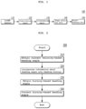
- FIG. 2 is a flowchart, of an object-tracking method 200 according to an embodiment.
- FIG. 3 is a block diagram of an embodiment 150 A of the object-tracking unit 150 shown in FIG. 1 .
- the object-tracking unit 150 A shown in FIG. 3 may include a track generation unit 151 , an angle calculation unit 153 , a history unit 155 , an angle extraction unit 157 , and an angle correction unit 159 .
- the object-tracking method 200 shown in FIG. 2 is described as being performed by the object-tracking unit 150 A shown in FIG. 3 , the embodiment is not limited thereto.
- the object-tracking method 200 shown in FIG. 2 may be performed by an object-tracking unit configured differently from the object-tracking unit 150 A shown in FIG. 3 .
- the object-tracking unit 150 A shown in FIG. 3 may perform an object-tracking method configured differently from the object-tracking method 200 shown in FIG. 2 .
- the object-tracking unit 150 A shown in FIG. 3 may also be applied to an object-tracking apparatus configured differently from the object-tracking apparatus 100 shown in FIG. 1 .
- the object-tracking apparatus 100 shown in FIG. 1 determines a final heading angle of the track during every recognition period.
- the LiDAR sensor 110 , the preprocessing unit 120 , the clustering unit 130 , the shape analysis unit 140 , and the object-tracking unit 150 may operate to obtain the heading angle of the track of the object and may track the object using the same.
- the object-tracking apparatus 100 may determine the final heading angle of the track during every recognition period ( . . . , T ⁇ 1, T, T+1, . . . )
- “current recognition period” is denoted by “T”
- “previous recognition period”, which is immediately before the “current recognition period” is denoted by “T ⁇ 1”.
- steps 210 to 240 shown in FIG. 2 may be performed on each of the tracks.
- the heading angle of the track (hereinafter referred to as a “current velocity-based heading angle”) is obtained using the velocity in the current recognition period T (hereinafter referred to as the “current velocity”) of the track generated from the point cloud related to the object (step 210 ).
- step 210 may be performed by the track generation unit 151 and the angle calculation unit 153 shown in FIG. 3 .
- the track generation unit 151 may generate a track from the point cloud related to the object in order to track the object.
- the track generation unit 151 may receive the result of analysis by the shape analysis unit 140 through an input terminal IN and may generate a track for tracking the object using the same.
- the angle calculation unit 153 may calculate the current velocity-based heading angle of the track using the current velocity of the track generated by the track generation unit 151 and may output the calculated current velocity-based heading angle to the history unit 155 .
- FIG. 4 is a flowchart of an embodiment 210 A of step 210 shown in FIG. 2 .
- FIGS. 5 A and 5 B are diagrams for explaining step 210 A shown in FIG. 4 .
- step 210 A shown in FIG. 4 may be performed by the angle calculation unit 153 shown in FIG. 3 .
- the absolute velocity of the track in the current recognition period T is obtained (step 211 ).
- the absolute velocity AV of the track may be obtained by summing the relative velocity TCV of the track and the velocity SW of the host vehicle, as expressed using Equation 1 below.
- AV TCV+SVV [Equation 1]
- the host vehicle is a vehicle equipped with the LiDAR sensor 110 .
- the first threshold velocity VT 1 may be a value set in advance differently for each track or may be a fixed value set in advance regardless of the track. The embodiment is not limited to any specific value of the first threshold velocity VT 1 .
- the current velocity-based heading angle CVH may be obtained using the absolute longitudinal velocity AVV and the absolute lateral velocity AHV, which are components of the absolute velocity AV of the track TR (step 213 ).
- the current velocity-based heading angle CVH may be obtained from the absolute longitudinal velocity AVV and the absolute lateral velocity AHV using an arctangent, but the embodiment is not limited thereto.
- a difference between a previous velocity-based heading angle and a shape-based heading angle is obtained (step 214 ).
- the previous velocity-based heading angle is a heading angle obtained using the velocity of the track in the previous recognition period T ⁇ 1.
- the shape-based heading angle is a heading angle obtained using information about the shape of the track TR in the current recognition period T.
- the threshold difference TD may be a value set in advance differently for each track TR or may be a fixed value set in advance regardless of the track TR. The embodiment is not limited to any specific value of the threshold difference TD.
- the shape-based heading angle is determined to be the current velocity-based heading angle (step 216 ).
- the shape-based heading angle SH shown in FIG. 5 B may be determined to be the current velocity-based heading angle.
- the first threshold score TP 1 may be a value set in advance differently for each track TR or may be a fixed value set in advance regardless of the track TR. The embodiment is not limited to any specific value of the first threshold score TP 1 .
- FIG. 6 is a diagram illustrating the heading history HH.
- the heading history may include a plurality of regions, the number of which is calculated using Equation 2 below.
- N represents the number of regions that are sectioned for respective heading angles of the track TR included in the heading history HH and is a positive integer of 2 or more.
- x° represents the angular range of each of the regions included in the heading history HH.
- the number N of regions included in the heading history HH may be 12.
- the heading history HH shown in FIG. 6 may include first to twelfth regions 1 to 12 .
- the angular range of the first region 1 is ⁇ 15° to +15°
- the angular range of the second region 2 is +15° to +45°.
- the angular range of the third region 3 is +45° to +75°.
- the angular range of the fourth region 4 is +75° to +105°.
- the angular range of the fifth region 5 is +105° to +135°.
- the angular range of the sixth region 6 is +135° to +165°.
- the angular range of the seventh region 7 is +165° to ⁇ 165°.
- the angular range of the eighth region 8 is ⁇ 165° to ⁇ 135°.
- the angular range of the ninth region 9 is ⁇ 135° to ⁇ 105°.
- the angular range of the tenth region 10 is ⁇ 105° to ⁇ 75°.
- the angular range of the eleventh region 11 is ⁇ 75° to ⁇ 45°.
- the angular range of the twelfth region 12 is ⁇ 45° to ⁇ 15°.
- Each of the first to N th regions included in the heading history HH illustrated in FIG. 6 may have a cumulative score. The process of accumulating scores for each of the plurality of regions is described below with reference to FIG. 7 .
- the highest score XMP used in step 217 is the highest score among the cumulative scores of the first to N th regions included in the heading history HH.
- the region having the highest cumulative score among the first to N th regions included in the heading history HH is referred to as a “highest region”.
- the angle TPH of the highest region is determined to be the current velocity-based heading angle, as shown in FIG. 5 B (step 218 ).
- the angle of the highest region which is determined to be the current velocity-based heading angle, may be one of the angles falling within the angular range of the highest region.
- the angle of the highest region which is determined to be the current velocity-based heading angle, may be an intermediate angle in the angular range of the highest region.
- the first region 1 corresponds to the highest region.
- the intermediate angle in the angular range ( ⁇ 15° to +15°) of the first region 1 is 0°, which is the highest region, and 0° is determined to be the current velocity-based heading angle.
- the previous velocity-based heading angle PVH shown in FIG. 5 B may be determined to be the current velocity-based heading angle (step 219 ).
- the history unit 155 may accumulate scores associated with information about the current velocity-based heading angle and may incorporate the accumulated scores into the heading history (step 220 ).
- FIG. 7 is a flowchart, of an embodiment 220 A of step 220 shown in FIG. 2 .
- Step 220 A shown in FIG. 7 may be performed by the history unit 155 shown in FIG. 3 .
- a velocity ratio of the velocity having a smaller scalar value, among the absolute longitudinal velocity and the absolute lateral velocity, to the velocity having a larger scalar value is obtained (step 222 ).
- the velocity ratio may be expressed using Equation 3 below.
- VR represents the velocity ratio
- VMA represents the velocity having a larger scalar value, among the absolute longitudinal velocity and the absolute lateral velocity
- VMI represents the velocity having a smaller scalar value, among the absolute longitudinal velocity and the absolute lateral velocity.
- the reference ratio may be a value set in advance differently for each track TR or may be a fixed value set in advance regardless of the track TR.
- the embodiment is not limited to any specific value of the reference ratio.
- the target region is a region corresponding to the current velocity-based heading angle obtained in step 210 , among the first to N th regions in the heading history HH.
- the left region is a region adjacent to, and to the left of, the target region among the first to N th regions.
- the right region is a region adjacent to, and to the right of, the target region among the first to N th regions.
- the current velocity-based heading angle obtained in step 210 is 40°, among the first to twelfth regions 1 to 12 shown in FIG. 6
- the second region 2 is the target region
- the first region 1 is the left region
- the third region 3 is the right region.
- the score of the target region is decreased by a first score and increased by a second score and the score of each of the left region and the right region is increased by a third score (step 226 ). However, if the velocity ratio VR is greater than or equal to the reference ratio, the score of the target region is decreased by a fourth score and increased by a fifth score (step 228 ).
- the first score is 0.5
- the second score is 2
- each of the reference ratio, the third score, the fourth score, and the fifth score is 0.25.
- the score of the target region is decreased as follows.
- the score of the target region is increased as follows.
- the first to fifth scores are as described above, for example, when the current velocity-based heading angle obtained at the tenth step in the current recognition period T is 5°, when the previous velocity-based heading angle obtained at the tenth step in the previous recognition period T ⁇ 1 is also 5°, and when the first region among the regions in the heading history is the target region, scores to be assigned to the first region, the twelfth region, and the second region may be calculated as expressed using Equation 4 below.
- a 1 2 points ⁇ (0.5 points or 0.25 points)+2 points
- a 12 0.25 points ⁇ (0.5 points or 0.25 points)+0.25 points
- a 2 0.25 points ⁇ (0.5 points or 0.25 points)+0.25 points [Equation 4]
- A1 represents a score accumulated in the first region
- A12 represents a score accumulated in the twelfth region
- A2 represents a score accumulated in the second region.
- each of the minimum value and the maximum value that may be accumulated in the heading history may be a fixed value. For example, when the minimum value that may be accumulated in the heading history is 0, the smallest value that may be accumulated in each of the first to N th regions included in the heading history may not be less than 0. As such, the minimum value is the minimal limit value of the accumulated scores. Further, when the maximum value that may be accumulated in the heading history is 10, the largest value that may be accumulated in each of the first to N th regions included in the heading history may not be greater than 10. As such, the maximum value is the maximal limit value of the accumulated scores.
- step 220 (or step 220 A) of incorporating information into the heading history may be performed during every recognition period ( . . . , T ⁇ 1, T, T+1, . . . ).
- the heading history HH illustrated in FIG. 6 may be present for each of a plurality of tracks.
- the scores of regions in a heading history corresponding to the extinct or obsolete track may be initialized.
- the heading history corresponding to the extinct track may be deleted.
- a track related to the newly appeared object may be generated and accumulation of scores in each of the regions in a heading history may be started.
- a heading history related to a newly generated track may be generated.
- the angle extraction unit 157 extracts a heading angle of the track (hereinafter referred to as a “history-based heading angle”) using the heading history HH and outputs the extracted history-based heading angle to the angle correction unit 159 (step 230 ).
- FIG. 8 is a flowchart of an embodiment 230 A of step 230 shown in FIG. 2 .
- Step 230 A shown in FIG. 8 may be performed by the angle extraction unit 157 .
- a second threshold score TP 2 is checked (step 231 ).
- the second threshold score TP 2 may be a value set in advance differently for each track or may be a fixed value set in advance regardless of the track.
- the second threshold score TP 2 may be 4 points, but the embodiment is not limited to any specific value of the second threshold score TP 2 .
- the second threshold velocity VT 2 may be a value set in advance differently for each track or may be a fixed value set in advance regardless of the track.
- the second threshold velocity VT 2 may be 1.5 m/s, but the embodiment is not limited to any specific value of the second threshold velocity VT 2 .
- the current velocity-based heading angle obtained in step 210 is determined to be the history-based heading angle (step 239 ).
- the absolute velocity is less than the second threshold velocity VT 2 , whether a spacing distance GP between a region in the heading history HH into which a score has been incorporated in the previous recognition period T ⁇ 1 (hereinafter referred to as a “previous region”) and a region in the heading history HH into which a score has been incorporated in the current recognition period T (hereinafter referred to as a “current region”) is greater than a threshold distance TDI is checked (step 235 ).
- the threshold distance TDI may be a value set in advance differently for each track or may be a fixed value set in advance regardless of the track.
- the spacing distance GP may correspond to a spacing distance between the target region in the previous recognition period T ⁇ 1 and the target region in the current recognition period T, among the regions in the heading history.
- the threshold distance TDI may be determined to 1.
- the angle of the highest region is determined to be the history-based heading angle (step 237 ).
- the angle of the highest region which is determined to be the history-based heading angle in step 237 , may be an intermediate angle in the angular range of the highest region.
- the cumulative score of the first region 1 is the highest score, which is greater than the cumulative scores of the second to twelfth regions 2 to 12 , among the first to twelfth regions 1 to 12 included in the heading history HH shown in FIG. 6
- the first region 1 corresponds to the highest region.
- the intermediate angle in the angular range ( ⁇ 15° to +15°) of the first region 1 which is the highest region, is 0° and 0° is determined to be the history-based heading angle.
- the current velocity-based heading angle obtained in step 210 may be determined to be the history-based heading angle (step 239 ).
- step 231 when it is determined in step 231 that the highest score MXP is greater than the second threshold score TP 2 , the process gees to step 235 .
- step 237 described above is performed.
- step 237 the angle of the highest region corresponding to the highest score, among the regions in the heading history, is determined to be the history-based heading angle.
- step 239 is performed.
- step 239 the current velocity-based heading angle obtained in step 210 is determined to be the history-based heading angle.
- the angle correction unit 159 corrects the history-based heading angle using information about the shape of the track, determines the result of correction to a final heading angle in the current recognition period T, and outputs the final heading angle through an output terminal OUT (step 240 ).
- FIG. 9 is a flowchart of an embodiment 240 A of step 240 shown in FIG. 2 .
- FIGS. 10 - 12 are diagrams to help understand step 240 A shown in FIG. 9 .
- FIG. 10 is a diagram for explaining a candidate heading angle of the track TR.
- FIG. 11 is a diagram for explaining the candidate heading angle of the track TR depending on the shape of the track.
- FIG. 12 is a diagram showing a comparison between the candidate heading angles D 1 and D 2 of the track TR and the history-based heading angle 402 .
- Step 240 A shown in FIG. 9 may be performed by the angle correction unit 159 shown in FIG. 3 .
- step 230 information about the shape of the track is checked (step 241 ).
- one track TR may have a candidate heading angle corresponding to one of four directions D 1 , D 2 , D 3 and 154 based on the host vehicle 10 .
- one track TR has four candidate heading angles D 1 , D 2 , D 3 , and D 4 , as shown in FIG. 10 .
- shape information is present, one track TR has only two candidate heading angles.
- the shape of each of first, second, and fourth tracks TR 1 , TR 2 , and TR 4 is an I-shape IS and the shape of a third track TR 3 is an L-shape LS.
- each of the second, third, and fourth tracks TR 2 , TR 3 , and TR 4 has two candidate heading angles D 1 and D 2 and the first track TR 1 has two candidate heading angles D 3 and D 4 .
- step 241 a plurality of candidate heading angles included in shape information and the history-based heading angle are compared with each other to correct the history-based heading angle (steps 243 to 243 ).
- a candidate heading angle having a small difference from the history-based heading angle may be selected from among a plurality of candidate heading angles (step 243 ). For example, as illustrated in FIG. 12 , when the shape information has two candidate heading angles D 1 and D 2 , the history-based heading angle 402 and the two candidate heading angles D 1 and D 2 are compared with each other. In the case shown in FIG. 12 , among the two first and second candidate heading angles D 1 and D 2 , the first candidate heading angle D 1 has a smaller difference from the history-based heading angle 402 than the second candidate heading angle D 2 . Thus, the first candidate heading angle D 1 may be selected.
- the candidate heading angle is filtered (e.g. is low-pass filtered) based on the reliability of the selected candidate heading angle (steps 245 to 249 ).
- the reliability of the selected candidate heading angle is the reliability of the shape information searched in step 241 .
- whether the reliability is greater than threshold reliability is checked (step 245 ). For example, a weight of 0 to 1 may be assigned to the reliability and the assigned weight may be checked to inspect the reliability.
- the candidate heading angle selected in step 243 is determined to be the final heading angle (step 247 ). However, if the reliability is not greater than the threshold reliability, the history-based heading angle is determined to be the final heading angle (step 249 ).
- a computer-readable recording medium in which a program for executing the object-tracking method according to the embodiment is recorded may store a program for implementing a function of using the velocity of a track for tracking an object, generated from a point cloud related to the object, in a current recognition period T to obtain a current velocity-based heading angle of the track.
- the program may also implement, a function of accumulating scores associated with information about the current velocity-based heading angle and incorporating the accumulated scores into a heading history having regions sectioned for respective heading angles of the track.
- the program may further implement a function of obtaining a history-based heading angle of the track using the heading history.
- the program may also implement a function of correcting the history-based heading angle using information about the shape of the track and determining the result of correction to be a final heading angle in the current recognition period T.
- the function of obtaining the current velocity-based heading angle of the track may include a function of obtaining an absolute velocity of the track in the current recognition period T.
- the function of obtaining the current velocity-based heading angle of the track may also include a function of, when the absolute velocity is greater than or equal to a first threshold velocity, obtaining the current velocity-based heading angle using an absolute longitudinal velocity and an absolute lateral velocity, which are components of the absolute velocity.
- the function of obtaining the current velocity-based heading angle of the track may further include a function of, when the absolute velocity is less than the first threshold velocity, obtaining a difference between a previous velocity-based heading angle obtained using the velocity of the track in the previous recognition period T ⁇ 1 and a shape-based heading angle obtained using information about the shape of the track in the current recognition period T.
- the function of obtaining the current velocity-based heading angle of the track may further include a function of, when the difference is less than a threshold difference, determining the shape-based heading angle to be the current velocity-based heading angle.
- the function of obtaining the current velocity-based heading angle of the track may further include a function of, when the difference is greater than or equal to the threshold difference, checking whether the highest score, among the scores accumulated for each angle in the heading history, is greater than a first threshold score.
- the function of obtaining the current velocity-based heading angle of the track may further include a function of, when the highest score is greater than the first threshold score, determining the previous velocity-based heading angle to be the current velocity-based heading angle.
- the function of obtaining the current velocity-based heading angle of the track may also include a function of, when the highest score is less than or equal to the first threshold score, determining the angle of a region having the highest score, among the regions in the heading history, to be the current velocity-based heading angle.
- the function of accumulating scores and incorporating the accumulated scores into the heading history may include a function of obtaining a velocity ratio of the velocity having a smaller scalar value among the absolute longitudinal velocity and the absolute lateral velocity, to the velocity having a larger scalar value among the absolute longitudinal velocity and the absolute lateral velocity.
- the function of accumulating and incorporating may also include a function of checking whether the velocity ratio is less than a reference ratio.
- the function of accumulating and incorporating may further include a function of, when the velocity ratio is less than the reference ratio, decreasing the score of a target region corresponding to the current velocity-based heading angle, among the regions in the heading history, by a first score, increasing the score by a second score, and increasing the score of each of a left region and a right region, respectively adjacent to the left and the right of the target region, by a third score.
- the function of accumulating and incorporating may also include a function of, when the velocity ratio is greater than or equal to the reference ratio, decreasing the score of the target region by a fourth score and increasing the score by a fifth score.
- the function of obtaining the history-based heading angle may include a function of, when the highest score is less than or equal to a second threshold score, checking whether the absolute velocity is less than a second threshold velocity.
- the function of obtaining the history-based heading angle may also include a function of, when the absolute velocity is greater than or equal to the second threshold velocity, determining the current velocity-based heading angle to be the history-based heading angle.
- the function of obtaining the history-based heading angle may further include a function of, when the absolute velocity is less than the second threshold velocity, checking whether a spacing distance between a region in the heading history into which a score has been incorporated in the previous recognition period T ⁇ 1 and a region in the heading history into which a score has been incorporated in the current recognition period T is greater than a threshold distance.
- the function of obtaining the history-based heading angle may further include a function of, when the spacing distance is greater than the threshold distance, determining the angle of the region having the highest score, among regions in the heading history, to be the history-based heading angle.
- the function of obtaining the history-based heading angle may further include a function of, when the spacing distance is less than or equal to the threshold distance, determining the current velocity-based heading angle to be the history-based heading angle.
- the function of obtaining the history-based heading angle may further include a function of, when the highest score is greater than the second threshold score and the spacing distance is greater than the threshold distance, determining the angle of the region corresponding to the highest score, among regions in the heading history, to be the history-based heading angle.
- the function of obtaining the history-based heading angle may also include a function of, when the highest score is greater than the second threshold score and the spacing distance is less than or equal to the threshold distance, determining the current velocity-based heading angle to be the history-based heading angle.
- the function of correcting the history-based heading angle may include a function of checking information about the shape of the track and a function of comparing a plurality of candidate heading angles included in the shape information and the history-based heading angle so as to correct the history-based heading angle.
- the computer-readable recording medium includes all kinds of recording devices in which data that may be read by a computer system are stored.
- Examples of the computer-readable recording medium include a Read-Only Memory (ROM), a Random Access Memory (RAM), a Compact Disk ROM (CD-ROM), a magnetic tape, a floppy disc, and an optical data storage.
- the computer-readable recording medium can also be distributed over network-connected computer systems so that the computer-readable code is stored and executed in a distributed fashion. Also, functional programs, code, and code segments for accomplishing the object-tracking method can be easily construed by those, e.g. programmers, having ordinary skill in the art to which the present disclosure pertains.
- a history-based heading angle is obtained using a history about a heading angle of a track and the history-based heading angle is corrected using shape information.
- the method and apparatus for tracking an object and the recording medium storing a program to execute the method according to the disclosed embodiments it is possible to accurately and reliably extract a heading angle by reducing an error in the heading angle and thus to accurately track an object especially in a specific situation, for example, in a situation that when there is a possibility that the velocity is erroneously and suddenly calculated and thus an error is generated in a heading angle, which is extracted based on the velocity, due to low-speed movement of the track or traffic congestion, as well as a situation that the velocity of the track exceeds a predetermined level.
Landscapes
- Engineering & Computer Science (AREA)
- Physics & Mathematics (AREA)
- Electromagnetism (AREA)
- General Physics & Mathematics (AREA)
- Remote Sensing (AREA)
- Radar, Positioning & Navigation (AREA)
- Computer Networks & Wireless Communication (AREA)
- Automation & Control Theory (AREA)
- Transportation (AREA)
- Mechanical Engineering (AREA)
- Computer Vision & Pattern Recognition (AREA)
- Theoretical Computer Science (AREA)
- Mathematical Physics (AREA)
- Multimedia (AREA)
- Image Analysis (AREA)
Abstract
Description
AV=TCV+SVV [Equation 1]
A1=2 points−(0.5 points or 0.25 points)+2 points
A12=0.25 points−(0.5 points or 0.25 points)+0.25 points
A2=0.25 points−(0.5 points or 0.25 points)+0.25 points [Equation 4]
GP=|m−n| [Equation 5]
Claims (19)
Applications Claiming Priority (2)
| Application Number | Priority Date | Filing Date | Title |
|---|---|---|---|
| KR10-2020-0183557 | 2020-12-24 | ||
| KR1020200183557A KR20220092116A (en) | 2020-12-24 | 2020-12-24 | Method and apparatus for tracking object, and recording medium for recording program performing the method |
Publications (2)
| Publication Number | Publication Date |
|---|---|
| US20220203972A1 US20220203972A1 (en) | 2022-06-30 |
| US11807232B2 true US11807232B2 (en) | 2023-11-07 |
Family
ID=82070009
Family Applications (1)
| Application Number | Title | Priority Date | Filing Date |
|---|---|---|---|
| US17/463,681 Active 2042-03-16 US11807232B2 (en) | 2020-12-24 | 2021-09-01 | Method and apparatus for tracking an object and a recording medium storing a program to execute the method |
Country Status (3)
| Country | Link |
|---|---|
| US (1) | US11807232B2 (en) |
| KR (1) | KR20220092116A (en) |
| CN (1) | CN114675283A (en) |
Families Citing this family (2)
| Publication number | Priority date | Publication date | Assignee | Title |
|---|---|---|---|---|
| CN115494505B (en) * | 2022-09-22 | 2025-07-29 | 合肥保航汽车科技有限公司 | Method, device, equipment and medium for measuring target initial track |
| CN116039802A (en) * | 2022-12-26 | 2023-05-02 | 北京百度网讯科技有限公司 | Method for adjusting the collection direction of mobile chassis and sensors |
Citations (5)
| Publication number | Priority date | Publication date | Assignee | Title |
|---|---|---|---|---|
| US20190370545A1 (en) * | 2018-01-10 | 2019-12-05 | Quantum Interface, Llc | Ininterfaces, systems and apparatuses for constructing 3d ar environment overlays, and methods for making and using same |
| US20200132850A1 (en) * | 2018-04-23 | 2020-04-30 | Blackmore Sensors & Analytics, Llc | Lidar system for autonomous vehicle |
| US20200272160A1 (en) * | 2019-02-22 | 2020-08-27 | Uber Technologies, Inc. | Motion Prediction for Autonomous Devices |
| US20200298891A1 (en) * | 2019-03-23 | 2020-09-24 | Uatc, Llc | Perception and Motion Prediction for Autonomous Devices |
| US20220146676A1 (en) * | 2020-11-09 | 2022-05-12 | Waymo Llc | Doppler-assisted object mapping for autonomous vehicle applications |
Family Cites Families (6)
| Publication number | Priority date | Publication date | Assignee | Title |
|---|---|---|---|---|
| US7315299B2 (en) * | 2002-08-01 | 2008-01-01 | Nissan Motor Co., Ltd. | Multi-way input device and operating failure avoidance method using the same |
| JP2004125542A (en) * | 2002-10-01 | 2004-04-22 | Seiko Epson Corp | Navigation device, electronic device and program |
| CN106384540B (en) * | 2016-10-20 | 2019-04-19 | 深圳市元征科技股份有限公司 | Vehicle real-time track prediction technique and forecasting system |
| US10809364B2 (en) * | 2018-08-06 | 2020-10-20 | Luminar Technologies, Inc. | Determining relative velocity using co-located pixels |
| CN110455300B (en) * | 2019-09-03 | 2021-02-19 | 广州小鹏汽车科技有限公司 | Navigation method, navigation display device, vehicle and machine readable medium |
| CN111176269B (en) * | 2019-10-11 | 2022-07-05 | 中国第一汽车股份有限公司 | Course adjusting method and device of vehicle, vehicle and storage medium |
-
2020
- 2020-12-24 KR KR1020200183557A patent/KR20220092116A/en active Pending
-
2021
- 2021-09-01 US US17/463,681 patent/US11807232B2/en active Active
- 2021-10-08 CN CN202111169684.4A patent/CN114675283A/en active Pending
Patent Citations (5)
| Publication number | Priority date | Publication date | Assignee | Title |
|---|---|---|---|---|
| US20190370545A1 (en) * | 2018-01-10 | 2019-12-05 | Quantum Interface, Llc | Ininterfaces, systems and apparatuses for constructing 3d ar environment overlays, and methods for making and using same |
| US20200132850A1 (en) * | 2018-04-23 | 2020-04-30 | Blackmore Sensors & Analytics, Llc | Lidar system for autonomous vehicle |
| US20200272160A1 (en) * | 2019-02-22 | 2020-08-27 | Uber Technologies, Inc. | Motion Prediction for Autonomous Devices |
| US20200298891A1 (en) * | 2019-03-23 | 2020-09-24 | Uatc, Llc | Perception and Motion Prediction for Autonomous Devices |
| US20220146676A1 (en) * | 2020-11-09 | 2022-05-12 | Waymo Llc | Doppler-assisted object mapping for autonomous vehicle applications |
Also Published As
| Publication number | Publication date |
|---|---|
| KR20220092116A (en) | 2022-07-01 |
| CN114675283A (en) | 2022-06-28 |
| US20220203972A1 (en) | 2022-06-30 |
Similar Documents
| Publication | Publication Date | Title |
|---|---|---|
| CN107490794B (en) | Object identification processing device, object identification processing method and automatic driving system | |
| US20230184946A1 (en) | Vehicle Lidar System and Velocity Measuring Method Thereof | |
| CN114475615B (en) | Devices and methods for identifying driving lanes based on multiple sensors | |
| US11328516B2 (en) | Apparatus and method for associating sensor data in vehicle | |
| US12326499B2 (en) | Method for detecting moving objects in the surroundings of a vehicle, and motor vehicle | |
| CN111723724B (en) | Road surface obstacle recognition method and related device | |
| US11807232B2 (en) | Method and apparatus for tracking an object and a recording medium storing a program to execute the method | |
| CN111136648B (en) | Mobile robot positioning method and device and mobile robot | |
| US12546889B2 (en) | Sensor information fusion method and apparatus | |
| KR20220041485A (en) | Method and apparatus for tracking an object using LIDAR sensor, vehicle including the apparatus, and recording medium for recording program performing the method | |
| CN114296095A (en) | Method, device, vehicle and medium for extracting effective target of automatic driving vehicle | |
| KR20190081334A (en) | Method for tracking moving trajectory based on complex positioning and apparatus thereof | |
| US20220179080A1 (en) | Apparatus and method for tracking an object using a lidar sensor | |
| US12535593B2 (en) | Object detection method and object tracking device using lidar sensor | |
| US12292507B2 (en) | Method and apparatus for detecting curb using LiDAR sensor and recording medium storing program to execute the method | |
| CN119295537B (en) | A rail transit obstacle recognition method and device based on time-series point cloud superposition | |
| KR102228278B1 (en) | Apparatus and Method for Recognizing Lane Using Lidar Sensor | |
| US12043270B2 (en) | Method and apparatus for tracking object and recording medium storing program to execute the method | |
| JP2021117051A (en) | Object detection method and object detector | |
| US11922670B2 (en) | System for extracting outline of static object and method thereof | |
| US12020464B2 (en) | Method of determining an orientation of an object and a method and apparatus for tracking an object | |
| US11267130B2 (en) | Robot localization method and apparatus and robot using the same | |
| US20240312029A1 (en) | Apparatus For Tracking Objects And Method Thereof | |
| US20250061683A1 (en) | Apparatus For Recognizing Object And Method Thereof | |
| US20240019545A1 (en) | Method for extracting outline of object in vehicle and vehicle thereof |
Legal Events
| Date | Code | Title | Description |
|---|---|---|---|
| AS | Assignment |
Owner name: KIA CORPORATION, KOREA, REPUBLIC OF Free format text: ASSIGNMENT OF ASSIGNORS INTEREST;ASSIGNOR:YOO, MIN KYUN;REEL/FRAME:057352/0920 Effective date: 20210818 Owner name: HYUNDAI MOTOR COMPANY, KOREA, REPUBLIC OF Free format text: ASSIGNMENT OF ASSIGNORS INTEREST;ASSIGNOR:YOO, MIN KYUN;REEL/FRAME:057352/0920 Effective date: 20210818 |
|
| FEPP | Fee payment procedure |
Free format text: ENTITY STATUS SET TO UNDISCOUNTED (ORIGINAL EVENT CODE: BIG.); ENTITY STATUS OF PATENT OWNER: LARGE ENTITY |
|
| STPP | Information on status: patent application and granting procedure in general |
Free format text: DOCKETED NEW CASE - READY FOR EXAMINATION |
|
| STPP | Information on status: patent application and granting procedure in general |
Free format text: NON FINAL ACTION MAILED |
|
| STPP | Information on status: patent application and granting procedure in general |
Free format text: RESPONSE TO NON-FINAL OFFICE ACTION ENTERED AND FORWARDED TO EXAMINER |
|
| STPP | Information on status: patent application and granting procedure in general |
Free format text: NOTICE OF ALLOWANCE MAILED -- APPLICATION RECEIVED IN OFFICE OF PUBLICATIONS |
|
| STPP | Information on status: patent application and granting procedure in general |
Free format text: PUBLICATIONS -- ISSUE FEE PAYMENT VERIFIED |
|
| STCF | Information on status: patent grant |
Free format text: PATENTED CASE |