US11798765B2 - Electromagnetic relay - Google Patents
Electromagnetic relay Download PDFInfo
- Publication number
- US11798765B2 US11798765B2 US16/518,719 US201916518719A US11798765B2 US 11798765 B2 US11798765 B2 US 11798765B2 US 201916518719 A US201916518719 A US 201916518719A US 11798765 B2 US11798765 B2 US 11798765B2
- Authority
- US
- United States
- Prior art keywords
- cover
- housing
- side part
- adhesive
- outer side
- Prior art date
- Legal status (The legal status is an assumption and is not a legal conclusion. Google has not performed a legal analysis and makes no representation as to the accuracy of the status listed.)
- Active, expires
Links
Images


Classifications
-
- H—ELECTRICITY
- H01—ELECTRIC ELEMENTS
- H01H—ELECTRIC SWITCHES; RELAYS; SELECTORS; EMERGENCY PROTECTIVE DEVICES
- H01H50/00—Details of electromagnetic relays
- H01H50/02—Bases; Casings; Covers
- H01H50/023—Details concerning sealing, e.g. sealing casing with resin
-
- H—ELECTRICITY
- H01—ELECTRIC ELEMENTS
- H01H—ELECTRIC SWITCHES; RELAYS; SELECTORS; EMERGENCY PROTECTIVE DEVICES
- H01H51/00—Electromagnetic relays
- H01H51/29—Relays having armature, contacts, and operating coil within a sealed casing
-
- H—ELECTRICITY
- H01—ELECTRIC ELEMENTS
- H01H—ELECTRIC SWITCHES; RELAYS; SELECTORS; EMERGENCY PROTECTIVE DEVICES
- H01H2223/00—Casings
- H01H2223/044—Protecting cover
-
- H—ELECTRICITY
- H01—ELECTRIC ELEMENTS
- H01H—ELECTRIC SWITCHES; RELAYS; SELECTORS; EMERGENCY PROTECTIVE DEVICES
- H01H50/00—Details of electromagnetic relays
- H01H50/02—Bases; Casings; Covers
- H01H50/04—Mounting complete relay or separate parts of relay on a base or inside a case
- H01H50/041—Details concerning assembly of relays
- H01H50/043—Details particular to miniaturised relays
Definitions
- the present invention relates to an electromagnetic relay, and in particular, relates to a sealed-type electromagnetic relay the interior of which is sealed by an adhesive.
- JP S61-119237 U discloses an electromagnetic relay the interior of which is sealed by the application of an adhesive to a gap between a housing, which houses the constituent components of the electromagnetic relay, and a cover.
- the cover is a thin molded part made of a resin. Since distortion may occur in the thin cover in some cases, the gap between the case and the cover may not be uniform, and the gap between the case and the cover may be small, depending on the position.
- the electromagnetic relay comprises a housing, a cover, an adhesive which is interposed and filled in a gap between a side part of the housing and an inner surface of the cover, and a projection which is formed on at least one of the side part and the inner surface.
- a sealed-type electromagnetic member having no sealing failures can be provided.
- FIG. 1 is a perspective view of the electromagnetic relay according to a first embodiment.
- FIG. 2 is an exploded perspective view of the electromagnetic relay.
- FIG. 3 is a perspective view of the electromagnetic relay in which the cover has been removed.
- FIG. 4 is a perspective view of a housing according to the first embodiment.
- FIG. 5 is a side view of the housing.
- FIG. 6 is a bottom view of the electromagnetic relay.
- FIG. 7 is an enlarged bottom view of a projection according to the first embodiment.
- FIG. 8 is an enlarged bottom view of a modified projection.
- FIG. 9 is an enlarged bottom view of a modified projection.
- FIG. 10 is an enlarged perspective view of the projection.
- FIG. 11 is an enlarged perspective view of a modified projection.
- FIG. 12 is an enlarged perspective view of a modified projection.
- FIG. 13 is a bottom view of an electromagnetic relay according to a second embodiment.
- FIG. 14 is an enlarged bottom view of the electromagnetic relay.
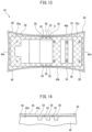
- FIG. 15 is a perspective view of a housing including a first recess according to the second embodiment.
- FIG. 16 is a perspective view of the housing with a modified first recess according to the second embodiment.
- FIG. 17 is a perspective view of the housing with a modified first recess and a second recess according to the second embodiment.
- the embodiments of an electromagnetic relay (hereinafter, “relay”) will be described below with reference to the attached drawings.
- the relay includes a housing and a cover, and the interior of the relay is sealed by an adhesive.
- FIG. 1 is a perspective view of relay 2 .
- FIG. 2 is an exploded perspective view of the relay 2 .
- the relay 2 includes a housing 4 in which constituent components are incorporated, and a box-shaped cover 6 which encloses the housing 4 .
- the housing 4 and the cover 6 are molded parts made of a resin.
- the components incorporated in the housing 4 include contact springs, an electromagnet, a hinge spring 8 , an armature 10 , and a card 12 .
- the contact spring includes a movable spring 14 having terminals 14 a and 14 b , a fixed break spring 16 having terminals 16 a and 16 b , and a fixed make spring 18 having terminals 18 a and 18 b .
- the electromagnet includes a coil assembly 20 , a yoke 22 , and an iron core 24 .
- the coil assembly 20 includes terminals 20 a and 20 b , a coil 20 c , and a bobbin 20 d on which the coil 20 c is wound.
- the relay 2 excites the electromagnet when a voltage is applied between the terminals 20 a and 20 b .
- the armature 10 is attracted to the iron core 24 due to the excitation of the electromagnet.
- the card 12 is associated with the armature 10 , and the movable spring 14 moves in accordance with the attraction of the armature 10 to iron core 24 , whereby the movable spring 14 and the make spring 18 are brought into contact with each other.
- the movable spring 14 and the break spring 16 contact each other.
- the hinge spring 8 is attached to the armature 10 and the yoke 22 so as to elastically bias the armature 10 away from the iron core 24 .
- the relay 2 opens and closes the contacts.
- the configuration described above is one example, and arbitrary components and principles can be used.
- the break-side contact spring may be omitted.
- FIG. 3 is a perspective view of the relay 2 from which the cover has been removed.
- FIG. 4 is a perspective view of the housing 4 .
- FIG. 5 is a side view of the housing 4 .
- the housing 4 includes side parts 26 and 28 , a bottom part 30 , and a top part 32 .
- the side part 26 includes surfaces 26 a , 26 b , and 26 c , a recess 26 d , and an aperture 26 e .
- the bottom part 30 includes a surface 30 a , and a protrusion 30 b.
- Projections 34 are formed on the portion of the surface 26 a closest to the bottom part 30 .
- An arbitrary number of projections 34 are formed.
- the side part 26 may not include the recess 26 d and the aperture 26 e . Furthermore, the entirety of the side part 26 may be formed as a single surface.
- the side part 28 has the same configuration as the side part 26 .
- the cover 6 includes side parts 6 a and 6 b , side parts 6 c and 6 d , and a top part 6 e .
- the cover 6 is open at the lower side of the relay 2 .
- FIG. 6 illustrates a bottom view of the relay 2 .
- the cover 6 is represented by the rectangular outline. Note that in FIG. 6 , due to the occurrence of warpage, the contour of the cover 6 is deformed from a rectangular shape to a curved shape.
- the cover 6 further includes an inner surface 36 a .
- the inner surface 36 a and the surface 26 a face each other.
- the cover 6 is formed, for example, as a thin resin part having a thickness of less than 1 mm, and as illustrated in FIG. 6 , warpage occurs after molding such that the cover 6 bends inward near the center of each side near the open end 36 .
- the degree of warpage depends on the thickness of cover 6 and the lengths of the sides thereof as compared with the same material and molding conditions. For example, the warpage is reduced as the thickness of the cover 6 increases. Furthermore, the warpage is reduced as the side length of the cover 6 decreases. In FIG. 6 , the warpage between the side parts 6 a and 6 b and the side parts 6 c and 6 d is less in the side parts 6 c and 6 d , which have shorter lengths.
- the adhesive 38 is arranged on the lower surface side of the relay 2 by, for example, application.
- the adhesive 38 is made of an epoxy resin, and includes a primary agent and a curing agent.
- the cross-hatched portion in FIG. 6 represents the adhesive 38 .
- the adhesive 38 is applied to the surface 30 a and the gap 40 between the housing 4 and the cover 6 .
- the adhesive 38 in a liquid state is applied, the adhesive applied to the surface 30 a flows into the gap 40 prior to curing.
- the adhesive 38 is not applied to the protrusion 30 b .
- the amount of adhesive 38 can be reduced while securing sufficient adhesive strength for the adhesive 38 to secure the housing 4 and the cover 6 to each other, whereby a cost reduction in the relay 2 can be realized.
- FIG. 7 is an enlarged view of the area “A” surrounded by the dashed line in FIG. 6 , which represents an enlarged view of the vicinity of the center of the warpage of the side part 6 a.
- Projections 34 are arranged in the vicinity of the center of the side part 6 a at positions facing the surface 36 a , and the tips thereof contact the inner surface 36 a . Since the projections 34 contact the inner surface 36 a , the center portion of the inner surface 36 a , which is bent inward, is pushed outward. Since the projections 34 push the inner surface 36 a outwardly, warpage of the open end 36 can be at least partially corrected, whereby the gap 40 can be secured across the entirety of the open end 36 .
- the gap 40 can be secured across the entirety of the open end 36 , and thus, a sufficient amount of the adhesive 38 can be applied seamlessly between the surface 26 a and the housing 4 . Furthermore, when the adhesive 38 is formed from an adhesive including a primary agent and a curing agent, if the gap 40 is secured across the entirety of the open end 36 , separation of the primary agent and the curing agent can be prevented, and the adhesive can be appropriately cured. It is preferable that the width of the gap 40 is about 0.1 mm at the narrowest point thereof, and the height of the projection 34 is preferably 0.1 mm.
- the projections 34 are formed in arbitrary positions of the side part 26 for contacting and pressing the side part 6 a .
- the projections 34 may be formed in arbitrary positions on the surfaces 26 a and 26 c . Furthermore, when the entirety of the side part 26 is formed as a single surface, projections 34 may be formed at arbitrary positions of this surface.
- Projections 34 are also formed on the side part 28 . Furthermore, projections 34 are formed in arbitrary positions for contacting and pushing the side part 6 c or 6 d.
- projections 34 are formed on the inner surface 36 a , and contact and press the surface 26 a , which is opposite thereto, whereby the gap 40 can be secured across the entirety of the open end 36 .
- projections 34 may be formed on both the inner surface 36 a and the surface 26 a .
- the projections 34 may be formed on the cover 6 and the housing 4 so as to alternate. By forming projections 34 on both the housing 4 and the cover 6 , the contact area of the housing 4 and the cover 6 with the adhesive 38 is increased, and thus, the adhesive strength between the adhesive 38 and the housing 4 and the cover 6 can be increased.
- the projection 34 is tapered, and is formed in a square frustum shape as illustrated in FIG. 10 .
- the projection 34 may be formed as a quadrilateral column extending from the lower end to the upper end of the surface of the housing 4 or the cover 6 .
- FIG. 11 depicts a projection 34 which extends from the lower end of the surface 26 a and which is formed as a quadrilateral column having a trapezoidal base.
- the tapered shape facilitates injection molding.
- the projection 34 may be formed in the spherical shape illustrated in FIG. 12 .
- the spherical shape includes a hemisphere shape. With a shape lacking corners such as a spherical shape, the projection 34 is less likely to be scraped when contacting the housing 4 or the cover 6 . Thus, it is possible to prevent the swarf, which may be generated as a result of the scraping, from entering into the interior of the housing 4 .
- Relay 42 according to a second embodiment will be described using FIGS. 13 to 17 .
- the structure of the relay 42 is the same as that of the relay 2 , and thus, an explanation therefor will not be repeated.
- FIG. 13 is a bottom view of the relay 42 .
- the relay 42 includes a cover 44 , and a housing 46 .
- the cover 44 includes side parts 44 a and 44 b , side parts 44 c and 44 d , and an inner surface 48 a.
- FIG. 14 is an enlarged view of the area B encircled by the dashed line in FIG. 13 .
- the area B depicts an enlarged view of the warpage in the vicinity of the center of the side part 44 a .
- FIG. 15 is a perspective view of the housing 46 , which is assembled with a coil assembly 50 .
- the housing 46 includes side parts 52 and 54 .
- the side part 52 includes a surface 52 a and a surface 52 b.
- First recesses 56 are formed in the surface 52 a in the vicinity of the center of the cover 44 so as to be open on the lower and upper ends of the surface 52 a .
- One end of each first recess 56 is open toward the open end 48 side.
- An arbitrary number of first recesses 56 are formed.
- the entirety of the side part 52 may be formed as a single surface.
- the first recesses 56 are formed so as to be open on the lower and upper ends of the side part 52 .
- FIG. 16 is a perspective view of the housing 46 with a modified first recess 56 .
- the first recesses 56 in FIG. 16 are open on the bottom end of the surface 52 , and are formed in cubic shapes.
- the width of the gap 58 between the cover 44 and the housing 46 is reduced in the vicinity of the center of the cover 44 .
- the housing 46 includes first recesses 56 , and the adhesive 60 can be applied in the first recesses 56 , a sufficient amount of adhesive 60 can be applied between the surface 52 a and the inner surface 48 a without interruption.
- the adhesive 60 is formed from an adhesive including a primary agent and a curing agent, since the adhesive 60 can flow into the first recesses 56 in the vicinity of the warpage of the cover 44 , whereby bleeding can be prevented and the adhesive can be appropriately cured.
- projections 62 are formed by the first recesses 56 .
- the contact area between the housing 46 and the adhesive 60 can be increased by the projections 62 , whereby the adhesive strength therebetween can be increased.
- the depths of the first recesses 56 and the heights of the projections 62 are assumed to be, for example, approximately 1 mm.
- the contact between the side part 44 a and the projections 62 depends on the degree of warpage of the cover 44 . However, the warpage of the side part 44 a can be reduced by supporting the side part 44 a with which the projections 62 contact.
- FIG. 17 is a perspective view of a modified example of the relay 42 .
- the housing 46 illustrated in FIG. 17 includes a second recess 64 in addition to the first recesses 56 .
- the first recesses 56 and the second recess 64 are formed in the surface 52 a , and the second recess 64 communicates with one end of each first recess 56 .
- the second recess 64 is formed in a position separated from the open end 48 with respect to the first recesses 56 .
- the second recess 64 may be open on both ends of the surface 52 a .
- the second recess 64 may not be open on both ends of the surface 52 a , and may be formed so as to be open only on the cover 44 side.
- Adhesive 60 is filled in the first recesses 56 and the second recess 64 .
- adhesive 60 By filling the adhesive 60 in not only the first recesses 56 but also in the second recess 64 , adhesive strength can be further improved.
- first recesses 56 and the second recess 64 may have arbitrary shapes.
- first recesses 56 and the second recess 64 may be tapered, or may be curved.
- first recesses 56 and the second recess 64 may be formed at arbitrary positions in the housing 46 so as to increase adhesive strength.
- a recess may be formed in the side part 54 .
- the first recesses 56 and the second recess 64 may be formed in the cover 44 .
- the first recesses 56 are open toward the open end 48 side, and the second recess 64 communicates with one end of each first recess 56 and is formed in a position away from the open end 48 with respect to the first recess 56 .
- the first recesses 56 may be formed in the housing 46 and the second recess 64 may be formed in the cover 44 .
- the first recesses 56 and the second recess 64 communicate with each other when the cover 44 contacts the housing 46 .
- the cover 44 and the housing 46 are resin parts, providing the first recesses 56 and the second recess 64 in separate parts facilitates individual injection molding.
Landscapes
- Physics & Mathematics (AREA)
- Electromagnetism (AREA)
- Switch Cases, Indication, And Locking (AREA)
- Casings For Electric Apparatus (AREA)
Abstract
Description
Claims (3)
Priority Applications (1)
| Application Number | Priority Date | Filing Date | Title |
|---|---|---|---|
| US18/474,002 US20240021387A1 (en) | 2018-07-31 | 2023-09-25 | Electromagnetic relay |
Applications Claiming Priority (2)
| Application Number | Priority Date | Filing Date | Title |
|---|---|---|---|
| JP2018-143628 | 2018-07-31 | ||
| JP2018143628A JP7204365B2 (en) | 2018-07-31 | 2018-07-31 | electromagnetic relay |
Related Child Applications (1)
| Application Number | Title | Priority Date | Filing Date |
|---|---|---|---|
| US18/474,002 Division US20240021387A1 (en) | 2018-07-31 | 2023-09-25 | Electromagnetic relay |
Publications (2)
| Publication Number | Publication Date |
|---|---|
| US20200043687A1 US20200043687A1 (en) | 2020-02-06 |
| US11798765B2 true US11798765B2 (en) | 2023-10-24 |
Family
ID=69229840
Family Applications (2)
| Application Number | Title | Priority Date | Filing Date |
|---|---|---|---|
| US16/518,719 Active 2040-01-28 US11798765B2 (en) | 2018-07-31 | 2019-07-22 | Electromagnetic relay |
| US18/474,002 Abandoned US20240021387A1 (en) | 2018-07-31 | 2023-09-25 | Electromagnetic relay |
Family Applications After (1)
| Application Number | Title | Priority Date | Filing Date |
|---|---|---|---|
| US18/474,002 Abandoned US20240021387A1 (en) | 2018-07-31 | 2023-09-25 | Electromagnetic relay |
Country Status (3)
| Country | Link |
|---|---|
| US (2) | US11798765B2 (en) |
| JP (1) | JP7204365B2 (en) |
| CN (1) | CN110783143B (en) |
Families Citing this family (3)
| Publication number | Priority date | Publication date | Assignee | Title |
|---|---|---|---|---|
| JP7326739B2 (en) * | 2018-12-27 | 2023-08-16 | オムロン株式会社 | electronic components |
| JP7638633B2 (en) | 2020-06-30 | 2025-03-04 | Fclコンポーネント株式会社 | Electromagnetic Relay |
| JP7400689B2 (en) * | 2020-10-20 | 2023-12-19 | オムロン株式会社 | electromagnetic relay |
Citations (25)
| Publication number | Priority date | Publication date | Assignee | Title |
|---|---|---|---|---|
| JPS5377337U (en) | 1976-11-30 | 1978-06-28 | ||
| JPS5731751U (en) | 1980-07-31 | 1982-02-19 | ||
| US4349693A (en) * | 1980-07-11 | 1982-09-14 | Siemens Aktiengesellschaft | Apparatus for sealing an electrical component |
| US4480243A (en) * | 1981-08-05 | 1984-10-30 | International Standard Electrik Corporation | Electromagnetic relay |
| JPS61119237A (en) | 1984-11-14 | 1986-06-06 | キヤノン株式会社 | automatic vision test device |
| US4675987A (en) * | 1983-03-12 | 1987-06-30 | International Standard Electric Corporation | Method of sealing a relay |
| US4975545A (en) * | 1988-07-20 | 1990-12-04 | Wickes Manufacturing Company | Sealed relay assembly |
| US5079387A (en) * | 1990-01-31 | 1992-01-07 | Emerson Electric Co. | Electrical component with enclosure and method of manufacture thereof |
| JPH0778540A (en) | 1993-09-10 | 1995-03-20 | Fujitsu Ltd | Electromagnetic relay |
| US5911588A (en) * | 1995-06-09 | 1999-06-15 | Siemens Aktiengesellschaft | Arrangement of a relay on a plug base |
| JP2000260283A (en) | 1999-03-05 | 2000-09-22 | Omron Corp | Electromagnetic relay |
| JP2002367498A (en) | 2001-06-12 | 2002-12-20 | Omron Corp | Electromagnetic relay |
| US20050270129A1 (en) * | 2004-06-07 | 2005-12-08 | Simpler Networks Inc. | Electro-mechanical relay |
| US7157996B2 (en) * | 2003-07-02 | 2007-01-02 | Matsushita Electric Works, Ltd. | Electromagnetic switching device |
| US20150155759A1 (en) * | 2013-11-29 | 2015-06-04 | Denso Corporation | Driver device |
| US20150171709A1 (en) * | 2012-08-28 | 2015-06-18 | Mitsubishi Electric Corporation | Electric driving device and method for manufacturing electric driving device |
| JP2015176754A (en) | 2014-03-14 | 2015-10-05 | オムロン株式会社 | Electronic device seal structure and electromagnetic relay using the electronic device seal structure |
| US20150333600A1 (en) * | 2012-10-01 | 2015-11-19 | Mitsubishi Electric Corporation | Electric drive apparatus |
| US20160204670A1 (en) * | 2015-01-08 | 2016-07-14 | Denso Corporation | Drive device |
| US20170229270A1 (en) * | 2016-02-04 | 2017-08-10 | Fujitsu Component Limited | Electromagnetic relay |
| US9754747B1 (en) | 2016-04-25 | 2017-09-05 | Song Chuan Precision Co., Ltd. | Relay device |
| US20180219449A1 (en) * | 2017-01-31 | 2018-08-02 | Denso Corporation | Drive apparatus |
| US20180287455A1 (en) * | 2017-03-30 | 2018-10-04 | Nidec Tosok Corporation | Electric actuator |
| US20190207474A1 (en) * | 2017-12-28 | 2019-07-04 | Nidec Tosok Corporation | Electric actuator |
| US20190214926A1 (en) * | 2016-09-30 | 2019-07-11 | Nidec Tosok Corporation | Control device, control method, motor, and electric oil pump |
Family Cites Families (7)
| Publication number | Priority date | Publication date | Assignee | Title |
|---|---|---|---|---|
| JP4190379B2 (en) * | 2003-09-12 | 2008-12-03 | 富士通コンポーネント株式会社 | Combined electromagnetic relay |
| US7990240B2 (en) * | 2007-10-18 | 2011-08-02 | Tyco Electronics Corporation | Epoxy sealed relay |
| EP2878355B1 (en) * | 2008-02-26 | 2018-06-27 | Mann + Hummel GmbH | Main filter element and filter device, especially air filter for a combustion engine |
| ES2389705T3 (en) * | 2008-09-29 | 2012-10-30 | Abb Technology Ag | Single coil actuator for low and medium voltage applications |
| KR20150016487A (en) * | 2012-06-08 | 2015-02-12 | 후지 덴키 기기세이교 가부시끼가이샤 | Electromagnetic contactor |
| CN103985600B (en) * | 2014-04-15 | 2015-10-21 | 明光市三友电子有限公司 | General highly sensitive type signal relay |
| CN106992098B (en) * | 2017-05-09 | 2020-03-24 | 浙江英洛华新能源科技有限公司 | Arc blocking type clapper relay |
-
2018
- 2018-07-31 JP JP2018143628A patent/JP7204365B2/en active Active
-
2019
- 2019-07-22 US US16/518,719 patent/US11798765B2/en active Active
- 2019-07-30 CN CN201910694689.5A patent/CN110783143B/en active Active
-
2023
- 2023-09-25 US US18/474,002 patent/US20240021387A1/en not_active Abandoned
Patent Citations (27)
| Publication number | Priority date | Publication date | Assignee | Title |
|---|---|---|---|---|
| JPS5377337U (en) | 1976-11-30 | 1978-06-28 | ||
| US4349693A (en) * | 1980-07-11 | 1982-09-14 | Siemens Aktiengesellschaft | Apparatus for sealing an electrical component |
| JPS5731751U (en) | 1980-07-31 | 1982-02-19 | ||
| US4480243A (en) * | 1981-08-05 | 1984-10-30 | International Standard Electrik Corporation | Electromagnetic relay |
| US4675987A (en) * | 1983-03-12 | 1987-06-30 | International Standard Electric Corporation | Method of sealing a relay |
| JPS61119237A (en) | 1984-11-14 | 1986-06-06 | キヤノン株式会社 | automatic vision test device |
| US4975545A (en) * | 1988-07-20 | 1990-12-04 | Wickes Manufacturing Company | Sealed relay assembly |
| US5079387A (en) * | 1990-01-31 | 1992-01-07 | Emerson Electric Co. | Electrical component with enclosure and method of manufacture thereof |
| JPH0778540A (en) | 1993-09-10 | 1995-03-20 | Fujitsu Ltd | Electromagnetic relay |
| US5911588A (en) * | 1995-06-09 | 1999-06-15 | Siemens Aktiengesellschaft | Arrangement of a relay on a plug base |
| JP2000260283A (en) | 1999-03-05 | 2000-09-22 | Omron Corp | Electromagnetic relay |
| JP2002367498A (en) | 2001-06-12 | 2002-12-20 | Omron Corp | Electromagnetic relay |
| US7157996B2 (en) * | 2003-07-02 | 2007-01-02 | Matsushita Electric Works, Ltd. | Electromagnetic switching device |
| US20050270129A1 (en) * | 2004-06-07 | 2005-12-08 | Simpler Networks Inc. | Electro-mechanical relay |
| US7323957B2 (en) * | 2004-06-07 | 2008-01-29 | Simpler Networks, Inc. | Electro-mechanical relay |
| US20150171709A1 (en) * | 2012-08-28 | 2015-06-18 | Mitsubishi Electric Corporation | Electric driving device and method for manufacturing electric driving device |
| US20150333600A1 (en) * | 2012-10-01 | 2015-11-19 | Mitsubishi Electric Corporation | Electric drive apparatus |
| US20150155759A1 (en) * | 2013-11-29 | 2015-06-04 | Denso Corporation | Driver device |
| US20170076893A1 (en) | 2014-03-14 | 2017-03-16 | Omron Corporation | Electronic-device seal structure and electromagnetic relay using said electronic-device seal structure |
| JP2015176754A (en) | 2014-03-14 | 2015-10-05 | オムロン株式会社 | Electronic device seal structure and electromagnetic relay using the electronic device seal structure |
| US20160204670A1 (en) * | 2015-01-08 | 2016-07-14 | Denso Corporation | Drive device |
| US20170229270A1 (en) * | 2016-02-04 | 2017-08-10 | Fujitsu Component Limited | Electromagnetic relay |
| US9754747B1 (en) | 2016-04-25 | 2017-09-05 | Song Chuan Precision Co., Ltd. | Relay device |
| US20190214926A1 (en) * | 2016-09-30 | 2019-07-11 | Nidec Tosok Corporation | Control device, control method, motor, and electric oil pump |
| US20180219449A1 (en) * | 2017-01-31 | 2018-08-02 | Denso Corporation | Drive apparatus |
| US20180287455A1 (en) * | 2017-03-30 | 2018-10-04 | Nidec Tosok Corporation | Electric actuator |
| US20190207474A1 (en) * | 2017-12-28 | 2019-07-04 | Nidec Tosok Corporation | Electric actuator |
Non-Patent Citations (2)
| Title |
|---|
| The Notification of Reasons for Refusal, and translation thereof, from counterpart Japanese Application No. 2018-143628, dated Apr. 5, 2022, 6 pp. |
| The Notification of Reasons for Refusal, and translation thereof, from counterpart Japanese Application No. 2018-143628, dated Aug. 9, 2022, 4 pp. |
Also Published As
| Publication number | Publication date |
|---|---|
| US20200043687A1 (en) | 2020-02-06 |
| JP2020021594A (en) | 2020-02-06 |
| US20240021387A1 (en) | 2024-01-18 |
| CN110783143A (en) | 2020-02-11 |
| JP7204365B2 (en) | 2023-01-16 |
| CN110783143B (en) | 2025-02-25 |
Similar Documents
| Publication | Publication Date | Title |
|---|---|---|
| US20240021387A1 (en) | Electromagnetic relay | |
| US10026577B2 (en) | Contact switching device | |
| CN103367042B (en) | Electromagnetic relay | |
| US20080231398A1 (en) | Electromagnetic relay | |
| US7956710B2 (en) | Electromagnetic relay | |
| US9613772B2 (en) | Contact device | |
| US9966214B2 (en) | Electromagnetic relay | |
| CN101826421B (en) | Electromagnetic relay | |
| US11742167B2 (en) | Relay | |
| WO2009139367A1 (en) | Electromagnetic relay | |
| US7046107B2 (en) | Contact device | |
| CN203150486U (en) | Electromagnetic relay | |
| CN101826419B (en) | Electromagnetic relay | |
| CN203787354U (en) | Electromagnetic relay | |
| CN104037023B (en) | electromagnetic relay and method for manufacturing the same | |
| WO2019176268A1 (en) | Contact opening-closing device | |
| US11295917B2 (en) | Terminal of relay, and relay | |
| US4481493A (en) | Polarized electromagnetic relay | |
| US12327704B2 (en) | Electromagnetic relay | |
| JP2023144142A (en) | electromagnetic relay | |
| JP3952582B2 (en) | Electromagnetic relay | |
| CN111801763A (en) | relay | |
| JP3826464B2 (en) | Electromagnetic relay | |
| CN203895365U (en) | Electromagnetic relay | |
| US12261004B2 (en) | Electromagnetic relay |
Legal Events
| Date | Code | Title | Description |
|---|---|---|---|
| AS | Assignment |
Owner name: FUJITSU COMPONENT LIMITED, JAPAN Free format text: ASSIGNMENT OF ASSIGNORS INTEREST;ASSIGNORS:KOBAYASHI, KOYURU;MIYANAGA, KAZUAKI;TAKAHASHI, KATSUYUKI;AND OTHERS;REEL/FRAME:049824/0225 Effective date: 20190617 |
|
| FEPP | Fee payment procedure |
Free format text: ENTITY STATUS SET TO UNDISCOUNTED (ORIGINAL EVENT CODE: BIG.); ENTITY STATUS OF PATENT OWNER: LARGE ENTITY |
|
| STPP | Information on status: patent application and granting procedure in general |
Free format text: APPLICATION DISPATCHED FROM PREEXAM, NOT YET DOCKETED |
|
| STPP | Information on status: patent application and granting procedure in general |
Free format text: DOCKETED NEW CASE - READY FOR EXAMINATION |
|
| STPP | Information on status: patent application and granting procedure in general |
Free format text: NON FINAL ACTION MAILED |
|
| STPP | Information on status: patent application and granting procedure in general |
Free format text: RESPONSE TO NON-FINAL OFFICE ACTION ENTERED AND FORWARDED TO EXAMINER |
|
| STPP | Information on status: patent application and granting procedure in general |
Free format text: NON FINAL ACTION MAILED |
|
| STPP | Information on status: patent application and granting procedure in general |
Free format text: FINAL REJECTION MAILED |
|
| STPP | Information on status: patent application and granting procedure in general |
Free format text: NON FINAL ACTION MAILED |
|
| STPP | Information on status: patent application and granting procedure in general |
Free format text: RESPONSE TO NON-FINAL OFFICE ACTION ENTERED AND FORWARDED TO EXAMINER |
|
| STPP | Information on status: patent application and granting procedure in general |
Free format text: NOTICE OF ALLOWANCE MAILED -- APPLICATION RECEIVED IN OFFICE OF PUBLICATIONS |
|
| STPP | Information on status: patent application and granting procedure in general |
Free format text: PUBLICATIONS -- ISSUE FEE PAYMENT VERIFIED |
|
| STCF | Information on status: patent grant |
Free format text: PATENTED CASE |