US11795772B2 - Extrudable ball seat system and methodology - Google Patents
Extrudable ball seat system and methodology Download PDFInfo
- Publication number
- US11795772B2 US11795772B2 US17/423,336 US202017423336A US11795772B2 US 11795772 B2 US11795772 B2 US 11795772B2 US 202017423336 A US202017423336 A US 202017423336A US 11795772 B2 US11795772 B2 US 11795772B2
- Authority
- US
- United States
- Prior art keywords
- diameter section
- ball seat
- ball
- smaller diameter
- extrudable
- Prior art date
- Legal status (The legal status is an assumption and is not a legal conclusion. Google has not performed a legal analysis and makes no representation as to the accuracy of the status listed.)
- Active, expires
Links
Images


Classifications
-
- E—FIXED CONSTRUCTIONS
- E21—EARTH OR ROCK DRILLING; MINING
- E21B—EARTH OR ROCK DRILLING; OBTAINING OIL, GAS, WATER, SOLUBLE OR MELTABLE MATERIALS OR A SLURRY OF MINERALS FROM WELLS
- E21B23/00—Apparatus for displacing, setting, locking, releasing or removing tools, packers or the like in boreholes or wells
- E21B23/04—Apparatus for displacing, setting, locking, releasing or removing tools, packers or the like in boreholes or wells operated by fluid means, e.g. actuated by explosion
- E21B23/0413—Apparatus for displacing, setting, locking, releasing or removing tools, packers or the like in boreholes or wells operated by fluid means, e.g. actuated by explosion using means for blocking fluid flow, e.g. drop balls or darts
-
- E—FIXED CONSTRUCTIONS
- E21—EARTH OR ROCK DRILLING; MINING
- E21B—EARTH OR ROCK DRILLING; OBTAINING OIL, GAS, WATER, SOLUBLE OR MELTABLE MATERIALS OR A SLURRY OF MINERALS FROM WELLS
- E21B34/00—Valve arrangements for boreholes or wells
- E21B34/06—Valve arrangements for boreholes or wells in wells
- E21B34/14—Valve arrangements for boreholes or wells in wells operated by movement of tools, e.g. sleeve valves operated by pistons or wire line tools
- E21B34/142—Valve arrangements for boreholes or wells in wells operated by movement of tools, e.g. sleeve valves operated by pistons or wire line tools unsupported or free-falling elements, e.g. balls, plugs, darts or pistons
Definitions
- various types of tools are actuated hydraulically via pressure applied downhole.
- Some types of pressure actuation involve moving an element, e.g. a ball, downhole along the interior of well tubing and into sealed engagement with a corresponding seat. This allows pressure to be increased along the interior of the tubing for performing desired functions, such as actuation of a downhole device or conducting a cementing operation.
- a ball is dropped and moved down through the well tubing into engagement with a corresponding ball seat. Once engaged, the pressure within the well tubing is increased to a predetermined pressure level sufficient to hydraulically actuate a downhole device, such as a liner hanger. The pressure may then be increased to a predetermined higher level sufficient to cause the ball and/or ball seat to break free and be discharged downhole.
- An extrudable ball seat is configured to be secured along a well tubing, e.g. along an interior of the well tubing.
- the extrudable ball seat comprises a larger diameter section and a smaller diameter section connected by a conical section.
- the conical section has an internal seating surface for receiving a corresponding element, e.g. a ball, in sealing engagement.
- the extrudable ball seat facilitates controlled extrusion of the element following the pressure application by providing the smaller diameter section with sufficient ductility to enable extrusion of the element under an increased predetermined pressure.
- the extrudable ball seat comprises at least one notch, e.g.
- the at least one notch enables the extrusion of elements, e.g. balls, having larger diameters and this allows more than one pressure actuation procedure to be performed using the same extrudable ball seat.
- FIG. 1 is a schematic illustration of an example of an extrudable ball seat positioned in a well system located in a borehole, e.g. a wellbore, according to an embodiment of the disclosure;
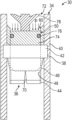
- FIG. 2 is an orthogonal view of an example of the extrudable ball seat, according to an embodiment of the disclosure
- FIG. 3 is schematic illustration of the extrudable ball seat positioned downhole in the well system and in which a first ball has been landed, according to an embodiment of the disclosure
- FIG. 4 is a schematic illustration similar to that of FIG. 3 showing pressure increased above the first ball, according to an embodiment of the disclosure
- FIG. 5 is a schematic illustration similar to that of FIG. 4 but showing the first ball extruded following sufficient increase of pressure above the first ball to deform the extrudable ball seat and to expel the first ball, according to an embodiment of the disclosure;
- FIG. 6 is a schematic illustration of the extrudable ball seat receiving a second ball having a larger diameter than the first ball, according to an embodiment of the disclosure
- FIG. 7 is a schematic illustration similar to that of FIG. 6 but showing the second ball landed in the extrudable ball seat, according to an embodiment of the disclosure
- FIG. 8 is a schematic illustration similar to that of FIG. 7 showing pressure increased in the well tubing above the second ball, according to an embodiment of the disclosure
- FIG. 9 is a schematic illustration similar to that of FIG. 8 but showing the second ball extruded following the sufficient increase of pressure above the second ball to plastically deform the extrudable ball seat and to initiate crack formation which facilitates expelling of the second ball, according to an embodiment of the disclosure;
- FIG. 10 a schematic illustration of the extrudable ball seat used in combination with another type of element, e.g. a dart, which has been dropped and moved downhole into engagement with a polished bore receptacle adjacent the extrudable ball seat, according to an embodiment of the disclosure;
- another type of element e.g. a dart
- FIG. 11 is a schematic illustration similar to that of FIG. 10 but showing an increase of pressure above the element, according to an embodiment of the disclosure
- FIG. 12 is a schematic illustration similar to that of FIG. 11 but showing the element moving through the extrudable ball seat upon further crack propagation, according to an embodiment of the disclosure;
- FIG. 13 is a schematic illustration similar to that of FIG. 12 but showing the element fully extruded through the extrudable ball seat, according to an embodiment of the disclosure.
- FIG. 14 is a schematic illustration of another embodiment of a well system having a plurality of extrudable ball seats, according to an embodiment of the disclosure.
- the disclosure herein generally involves a system and methodology which facilitate use of an element, e.g. a ball, for building up pressure in a downhole application.
- a ball is dropped and moved downhole along the interior of well tubing until engaging an extrudable ball seat.
- the ball effectively seals against the extrudable ball seat which allows pressure to be increased in the well tubing for performance of a variety of functions, such as actuating a hydraulic tool.
- the increased pressure may be used to hydraulically set a liner hanger, to release a liner hanger running tool, to facilitate a cementing operation, or to perform other actions downhole via pressure application.
- the extrudable ball seat is configured to be secured along an interior of the well tubing.
- the extrudable ball seat may be threadably engaged along the interior of the well tubing, latched into a corresponding notch in the well tubing, formed as part of a sub, e.g. housing, threadably engaged with corresponding joints of the well tubing, or otherwise secured at a desired position along the well tubing.
- the extrudable ball seat comprises a larger diameter section and a relatively smaller diameter section connected by a conical section.
- the conical section has an internal seating surface for receiving a corresponding element, e.g. a ball, in sealing engagement after the element is dropped into the well tubing and circulated downhole.
- ball refers to elements of a variety of shapes having a generally spherical or partially spherical engagement surface.
- the dropped element also may comprise darts or other types of elements which may be moved downhole along the well tubing for sealing engagement with the extrudable ball seat.
- the extrudable ball seat facilitates controlled extrusion of the element following the pressure application by providing the smaller diameter section with sufficient ductility to enable extrusion of the element under an increased predetermined pressure. For example, once a pressure actuation operation is completed the pressure in the well tubing may be increased sufficiently to extrude the element through the extrudable ball seat.
- the extrudable ball seat comprises at least one notch, e.g. a plurality of grooves, positioned to initiate crack propagation and thus a subsequent extrusion.
- the at least one notch enables the extrusion of elements, e.g. balls, having different diameters of at least a pre-set value. This allows more than one pressure actuation procedure to be performed using the same extrudable ball seat.
- the extrudable ball seat may be formed of a sufficiently ductile material, such as a suitable steel or stainless steel.
- the larger diameter section and smaller diameter section may be generally cylindrical.
- the at least one notch may be in the form of grooves machined in a generally axial direction along the smaller diameter section to facilitate generally longitudinal cracks. This enables a reduction in the extrusion pressure for extrusion of larger elements, e.g. larger balls.
- the size and ductility of the smaller diameter section and the conical section are selected so that cracks initiate at a pre-set value of element diameter. Balls or other elements having a diameter smaller than the pre-set diameter do not break/crack the extrudable ball seat.
- a polished bore receptacle may be placed adjacent the extrudable ball seat, e.g. above the extrudable ball seat, to receive certain types of larger elements, e.g. darts. Additionally, the construction of the extrudable ball seat facilitates extrusion of such larger elements following crack propagation. Crack propagation effectively enables passage of these larger elements through the extrudable ball seat using a reduced extrusion pressure.
- a well system 30 is illustrated as deployed in a borehole 32 , e.g. a wellbore.
- the well system 30 comprises a well tubing 34 deployed along the borehole 32 .
- the well tubing 34 may be in the form of drill pipe, a tubular running string, or various other types of tubing employed for downhole applications.
- the well system 30 comprises an extrudable ball seat 36 secured along an interior of the well tubing 34 via attachment features 38 .
- the attachment features 38 may comprise threads for threaded engagement along an interior of the well tubing 34 , a latch mechanism which latches into a corresponding notch in the well tubing 34 , or features for engagement with a corresponding housing 40 positioned along or within the well tubing 34 .
- the corresponding housing 40 may be formed as part of a sub threadably engaged with corresponding joints of the well tubing 34 .
- the extrudable ball seat 36 may be positioned and secured along the well tubing 34 by various other types of suitable mechanisms.
- the extrudable ball seat 36 comprises a larger diameter section 42 , a smaller diameter section 44 , and a conical section 46 extending between the larger diameter section 42 and the smaller diameter section 44 .
- the conical section 46 has an internal, conical sealing surface 48 , as further illustrated in FIG. 2 .
- the internal surface 48 provides an internal seat surface, e.g. an internal ball seat surface, for receiving an element 50 in sealing engagement.
- the element 50 is in the form of a ball 52 having a diameter 54 sized to enable the ball 52 to seal against the internal surface 48 when ball 52 is landed in the extrudable ball seat 36 after being circulated downhole along the interior of well tubing 34 .
- the smaller diameter section 44 and conical section 46 may be formed of a material which expands sufficiently to extrude the ball 52 (having the predetermined diameter 54 ) when sufficient pressure is applied after ball 52 is seated against internal, conical sealing surface 48 .
- the smaller diameter section 44 and the conical section 46 may be formed of a suitable steel material, stainless steel material, or other material which has suitable ductility to expand sufficiently when ball 52 is extruded through the extrudable ball seat 36 under increased pressure.
- the entire extrudable ball seat 36 may be a one-piece element formed of a single plastically deformable material, e.g. steel or stainless steel.
- the smaller diameter section 44 and/or the larger diameter section 42 may be formed generally as cylinders having cylindrical shapes extending in an axial direction along the well tubing 34 /housing 40 .
- the extrudable ball seat 36 further comprises at least one notch 56 positioned to facilitate crack propagation through a desired region of the extrudable ball seat 36 .
- the at least one notch 56 may be located in the smaller diameter section 44 .
- the at least one notch 56 comprises a plurality of grooves 58 which are machined or otherwise formed in the smaller diameter section 44 or other suitable section of extrudable ball seat 36 .
- grooves 58 are formed in a cylindrically shaped smaller diameter section 44 and oriented in a generally axial or longitudinal direction along the cylinder portion of the smaller diameter section 44 .
- a crack or cracks propagate from the at least one notch 56 to enable passage of the second ball (or other suitable element).
- the second ball is generally larger than the first ball 52 and when the diameter of the second ball is of at least the pre-set value, the crack or cracks are initiated and propagate.
- the expandability of the smaller diameter section 44 combined with the at least one notch 56 enables the extrusion of elements, e.g. balls, having different diameters. This capability allows more than one pressure actuation procedure to be performed using the same extrudable ball seat 36 .
- the well system 30 also may comprise a polished bore receptacle 60 .
- the polished bore receptacle 60 may be placed adjacent the extrudable ball seat 36 , e.g. directly uphole of the extrudable ball seat 36 .
- the polished bore receptacle 60 facilitates extrusion of other elements, e.g. darts, through the extrudable ball seat 36 following crack propagation.
- the polished bore receptacle 60 may be used to sealably receive large elements, e.g. darts, which are subsequently extruded through the cracked extrudable ball seat 36 with a reduced extrusion pressure.
- the first ball 52 is dropped into the well tubing 34 and circulated downhole until landed in the extrudable ball seat 36 , as illustrated in FIG. 3 .
- the ball 52 forms a seal with the internal sealing surface 48 .
- the extrudable ball seat 36 is formed of a suitable metal, e.g. steel, and the ball 52 also is formed of a metal material, e.g. steel, such that a metal-to-metal seal is created between the ball 52 and the internal seat surface 48 .
- pressure may be increased in the well tubing 34 to a desired actuation level for performance of a variety of functions, such as actuating a hydraulic tool.
- the actuation pressure may be used to hydraulically set a liner hanger, to release a liner hanger running tool, to facilitate a cementing operation, or to perform other actions downhole via pressure application.
- the pressure within well tubing 34 may be increased, as illustrated by arrows 62 in FIG. 4 , to an extrusion level.
- the extrusion level pressure may be, for example, a predetermined pressure above 2000 psi, although other applications may use a predetermined extrusion level pressure above 3000 psi or above another selected pressure value applied within well tubing 34 .
- the extrusion level pressure is used to extrude or expel the ball 52 through the extrudable ball seat 36 .
- the extrudable ball seat 36 may be plastically deformed during extrusion of ball 52 .
- the extrudable ball seat 36 is not broken, e.g. not cracked, during extrusion of ball 52 .
- the diameter of ball 52 and the ductility of the material forming at least portions of extrudable ball seat 36 may be selected to enable extrusion of the ball 52 without cracks forming in the extrudable ball seat 36 .
- a second ball 64 is dropped into well tubing 34 and circulated downhole to the extrudable ball seat 36 , as illustrated in FIG. 6 .
- the second ball 64 has a predetermined diameter 66 which is larger than the diameter 54 of first ball 52 .
- the second ball 64 is landed in the extrudable ball seat 36 such that a seal, e.g. a metal seal, is created between the second ball 64 and the internal seat surface 48 , as illustrated in FIG. 7 .
- pressure may be increased in the well tubing 34 to a desired actuation level for performance of a variety of functions, such as actuating a hydraulic tool.
- a second hydraulic actuation function may be performed after extrusion of the first ball 52 .
- the second application of actuation pressure may be used to hydraulically set a liner hanger, to release a liner hanger running tool, to facilitate a cementing operation, or to perform other actions downhole via pressure application.
- the pressure within well tubing 34 may be increased, as illustrated by arrows 68 in FIG. 8 , to a desired extrusion level.
- the extrusion pressure 68 may be comparable to the extrusion pressure 60 described above or it may be a different level, e.g. a higher pressure value.
- the pressure 68 is increased above the ball 64 to expand the extrudable ball seat 36 . If the diameter of second ball 64 is of at least a pre-set value, movement of the second ball 64 through extrudable ball seat 36 will initiate formation of a crack(s) 70 at the at least one notch 56 , as illustrated in FIG. 9 .
- the at least one notch 56 comprises the plurality of grooves 58 which are machined or otherwise formed in a given orientation and size to initiate a plurality of cracks at desired locations and in desired directions, e.g. in a longitudinal direction along the extrudable ball seat 36 .
- the element 50 may have other configurations, such as a dart 72 .
- dart 72 is dropped from the surface and circulated down through well tubing 34 until a nose 74 of the dart 72 is received inside the polished bore receptacle 60 .
- the dart 72 may comprise a seal or seals 76 positioned to cooperate with and seal against an interior surface of the polished bore receptacle 60 , as illustrated in FIG. 11 .
- the dart 72 may comprise swab cups 78 or other sealing elements coupled with the nose 74 .
- pressure may be increased above the dart 72 (or other tool) to move the dart downwardly and to plastically deform the extrudable ball seat 36 , thus initiating or causing further propagation of the crack(s) 70 as illustrated in FIG. 12 .
- the pressure used to expel the dart 72 (or other tool) through the expandable ball seat 36 is substantially reduced compared to what would otherwise be applied.
- the dart/tool 72 is readily extruded through and expelled from the extrudable ball seat 36 , as illustrated in FIG. 13 .
- extrudable ball seats 36 may be employed along tubing joints 80 forming overall well tubing 34 , as illustrated in FIG. 14 .
- a pair of the extrudable ball seats 36 may be positioned along well tubing 34 and may have different sizes.
- multiple hydraulic actuation functions may be performed downhole by using the plurality of extrudable ball seats 36 .
- the extrudable ball seats 36 may be used in many types of applications and along various types of well tubing 34 .
- at least one extrudable ball seat 36 may be used along well tubing 34 assembled in the form of a liner hanger running tool to facilitate hydraulic setting of a liner hanger.
- the size and configuration of the extrudable ball seat 36 may be adjusted according to the application.
- the configuration of the larger diameter section 42 , smaller diameter section 44 , and conical section 46 may be adjusted.
- the conical section 46 may have a variety of external configurations while retaining the conical internal seating surface 48 .
- the extrudable ball seat 36 may be used with various types of polished bore receptacles 60 and/or other cooperating components.
- the elements 50 may be in the form of balls or other types of tools. Additionally, the balls 52 , 64 may have various shapes including fully spherical shapes, partially spherical shapes, or other suitable shapes able to form a seal with the corresponding sealing seat surface 48 .
Landscapes
- Life Sciences & Earth Sciences (AREA)
- Engineering & Computer Science (AREA)
- Geology (AREA)
- Mining & Mineral Resources (AREA)
- Physics & Mathematics (AREA)
- Environmental & Geological Engineering (AREA)
- Fluid Mechanics (AREA)
- General Life Sciences & Earth Sciences (AREA)
- Geochemistry & Mineralogy (AREA)
- Extrusion Moulding Of Plastics Or The Like (AREA)
- Surgical Instruments (AREA)
- Pivots And Pivotal Connections (AREA)
Abstract
Description
Claims (18)
Applications Claiming Priority (4)
| Application Number | Priority Date | Filing Date | Title |
|---|---|---|---|
| EP19305105 | 2019-01-28 | ||
| EP19305105 | 2019-01-28 | ||
| EP19305105.9 | 2019-01-28 | ||
| PCT/EP2020/051616 WO2020156921A1 (en) | 2019-01-28 | 2020-01-23 | Extrudable ball seat system and methodology |
Publications (2)
| Publication Number | Publication Date |
|---|---|
| US20220081984A1 US20220081984A1 (en) | 2022-03-17 |
| US11795772B2 true US11795772B2 (en) | 2023-10-24 |
Family
ID=65409030
Family Applications (1)
| Application Number | Title | Priority Date | Filing Date |
|---|---|---|---|
| US17/423,336 Active 2040-08-03 US11795772B2 (en) | 2019-01-28 | 2020-01-23 | Extrudable ball seat system and methodology |
Country Status (4)
| Country | Link |
|---|---|
| US (1) | US11795772B2 (en) |
| EP (1) | EP3918179B1 (en) |
| SA (1) | SA521422596B1 (en) |
| WO (1) | WO2020156921A1 (en) |
Cited By (1)
| Publication number | Priority date | Publication date | Assignee | Title |
|---|---|---|---|---|
| US20230392472A1 (en) * | 2022-06-06 | 2023-12-07 | Halliburton Energy Services, Inc. | Method of reducing surge when running casing |
Families Citing this family (2)
| Publication number | Priority date | Publication date | Assignee | Title |
|---|---|---|---|---|
| US11988054B2 (en) * | 2020-03-13 | 2024-05-21 | Schlumberger Technology Corporation | System and method utilizing ball seat with locking feature |
| US11408253B1 (en) * | 2021-04-07 | 2022-08-09 | Baker Hughes Oilfield Operations Llc | Yieldable landing feature |
Citations (12)
| Publication number | Priority date | Publication date | Assignee | Title |
|---|---|---|---|---|
| US2196652A (en) * | 1936-10-10 | 1940-04-09 | Baker Oil Tools Inc | Apparatus for cementing well bores |
| US5143992A (en) | 1991-07-12 | 1992-09-01 | Shell Oil Company | Methathesis polymerizable adducts of a divinylcyclohydrocarbon and cyclopentadiene |
| US5146992A (en) | 1991-08-08 | 1992-09-15 | Baker Hughes Incorporated | Pump-through pressure seat for use in a wellbore |
| WO1998048143A1 (en) | 1997-04-22 | 1998-10-29 | Allamon Jerry P | Downhole surge pressure reduction system and method of use |
| US6739398B1 (en) * | 2001-05-18 | 2004-05-25 | Dril-Quip, Inc. | Liner hanger running tool and method |
| US20080048443A1 (en) * | 2006-06-02 | 2008-02-28 | Sub-Drill Supply Limited | Bimetal bore seal |
| US7469744B2 (en) | 2007-03-09 | 2008-12-30 | Baker Hughes Incorporated | Deformable ball seat and method |
| US20130081817A1 (en) | 2011-09-29 | 2013-04-04 | Halliburton Energy Services, Inc. | Responsively Activated Wellbore Stimulation Assemblies and Methods of Using the Same |
| US20140060813A1 (en) | 2012-09-06 | 2014-03-06 | Utex Industries, Inc. | Expandable fracture plug seat apparatus |
| US20150075818A1 (en) * | 2012-04-13 | 2015-03-19 | Saltel Industries | Pipe provided with a crimped metal element, and corresponding process |
| US20170122441A1 (en) | 2015-10-29 | 2017-05-04 | Baker Hughes Incorporated | Reduced Stress Ball Seat |
| US20180016867A1 (en) * | 2016-07-13 | 2018-01-18 | Schlumberger Technology Corporation | Soft seat retention |
-
2020
- 2020-01-23 US US17/423,336 patent/US11795772B2/en active Active
- 2020-01-23 WO PCT/EP2020/051616 patent/WO2020156921A1/en not_active Ceased
- 2020-01-23 EP EP20701466.3A patent/EP3918179B1/en active Active
-
2021
- 2021-07-25 SA SA521422596A patent/SA521422596B1/en unknown
Patent Citations (13)
| Publication number | Priority date | Publication date | Assignee | Title |
|---|---|---|---|---|
| US2196652A (en) * | 1936-10-10 | 1940-04-09 | Baker Oil Tools Inc | Apparatus for cementing well bores |
| US5143992A (en) | 1991-07-12 | 1992-09-01 | Shell Oil Company | Methathesis polymerizable adducts of a divinylcyclohydrocarbon and cyclopentadiene |
| US5146992A (en) | 1991-08-08 | 1992-09-15 | Baker Hughes Incorporated | Pump-through pressure seat for use in a wellbore |
| WO1998048143A1 (en) | 1997-04-22 | 1998-10-29 | Allamon Jerry P | Downhole surge pressure reduction system and method of use |
| US5960881A (en) * | 1997-04-22 | 1999-10-05 | Jerry P. Allamon | Downhole surge pressure reduction system and method of use |
| US6739398B1 (en) * | 2001-05-18 | 2004-05-25 | Dril-Quip, Inc. | Liner hanger running tool and method |
| US20080048443A1 (en) * | 2006-06-02 | 2008-02-28 | Sub-Drill Supply Limited | Bimetal bore seal |
| US7469744B2 (en) | 2007-03-09 | 2008-12-30 | Baker Hughes Incorporated | Deformable ball seat and method |
| US20130081817A1 (en) | 2011-09-29 | 2013-04-04 | Halliburton Energy Services, Inc. | Responsively Activated Wellbore Stimulation Assemblies and Methods of Using the Same |
| US20150075818A1 (en) * | 2012-04-13 | 2015-03-19 | Saltel Industries | Pipe provided with a crimped metal element, and corresponding process |
| US20140060813A1 (en) | 2012-09-06 | 2014-03-06 | Utex Industries, Inc. | Expandable fracture plug seat apparatus |
| US20170122441A1 (en) | 2015-10-29 | 2017-05-04 | Baker Hughes Incorporated | Reduced Stress Ball Seat |
| US20180016867A1 (en) * | 2016-07-13 | 2018-01-18 | Schlumberger Technology Corporation | Soft seat retention |
Non-Patent Citations (1)
| Title |
|---|
| International Search Report and Written Opinion issued in PCT Application PCT/EP2020/051616, dated Mar. 23, 2020 (15 pages). |
Cited By (2)
| Publication number | Priority date | Publication date | Assignee | Title |
|---|---|---|---|---|
| US20230392472A1 (en) * | 2022-06-06 | 2023-12-07 | Halliburton Energy Services, Inc. | Method of reducing surge when running casing |
| US12460507B2 (en) * | 2022-06-06 | 2025-11-04 | Halliburton Energy Services, Inc. | Apparatus and method of reducing surge when running casing |
Also Published As
| Publication number | Publication date |
|---|---|
| EP3918179A1 (en) | 2021-12-08 |
| SA521422596B1 (en) | 2024-01-29 |
| US20220081984A1 (en) | 2022-03-17 |
| EP3918179B1 (en) | 2024-03-13 |
| WO2020156921A1 (en) | 2020-08-06 |
Similar Documents
| Publication | Publication Date | Title |
|---|---|---|
| US5785120A (en) | Tubular patch | |
| US10612340B2 (en) | Wellbore plug isolation system and method | |
| US11795772B2 (en) | Extrudable ball seat system and methodology | |
| US7275600B2 (en) | Apparatus and method for expanding tubular members | |
| US7185701B2 (en) | Apparatus and method for radially expanding a tubular member | |
| US10094198B2 (en) | Big gap element sealing system | |
| US10794158B2 (en) | Method for sealing cavities in or adjacent to a cured cement sheath surrounding a well casing | |
| US7493946B2 (en) | Apparatus for radial expansion of a tubular | |
| US20190203557A1 (en) | Ball energized frac plug | |
| US8100186B2 (en) | Expansion system for expandable tubulars and method of expanding thereof | |
| WO2017114149A1 (en) | Mechanical and hydraulic dual-effect expansion device for well drilling with expandable tubular technology | |
| US20090266560A1 (en) | Monobore construction with dual expanders | |
| US20070029082A1 (en) | Apparatus and methods for creation of down hole annular barrier | |
| EP2150682B1 (en) | Downhole tubular expansion tool and method | |
| CN105971556B (en) | One kind can degradable metal bridge plug | |
| CN107075932B (en) | Improved isolation barrier | |
| NO20240870A1 (en) | System for expanding a tubular downhole | |
| US11965391B2 (en) | Downhole tool with sealing ring | |
| US20120132440A1 (en) | Expandable Screen Assembly and Method of Expanding a Plurality of Screens | |
| CN111684142A (en) | Well Completion Method and Completion System | |
| US20200063521A1 (en) | Methods and Systems Using an Expandable Sleeve in a Casing for Forming a Zonal Hydraulic Isolation | |
| EP3754155A1 (en) | Annular barrier with bite connection | |
| CN116291308B (en) | Quick drilling bridge plug | |
| US11346189B2 (en) | Method and apparatus for expanding wellbore casing | |
| US10597971B2 (en) | Method and system for inhibiting cement deposition in a jack and pull (JAP) expansion assembly |
Legal Events
| Date | Code | Title | Description |
|---|---|---|---|
| FEPP | Fee payment procedure |
Free format text: ENTITY STATUS SET TO UNDISCOUNTED (ORIGINAL EVENT CODE: BIG.); ENTITY STATUS OF PATENT OWNER: LARGE ENTITY |
|
| AS | Assignment |
Owner name: SALTEL INDUSTRIES SAS, FRANCE Free format text: ASSIGNMENT OF ASSIGNORS INTEREST;ASSIGNORS:ROSELIER, SAMUEL;BAJART, FRANCOIS;LEDUC, JULIE;AND OTHERS;REEL/FRAME:056877/0553 Effective date: 20190724 |
|
| STPP | Information on status: patent application and granting procedure in general |
Free format text: DOCKETED NEW CASE - READY FOR EXAMINATION |
|
| STPP | Information on status: patent application and granting procedure in general |
Free format text: NON FINAL ACTION MAILED |
|
| STPP | Information on status: patent application and granting procedure in general |
Free format text: NOTICE OF ALLOWANCE MAILED -- APPLICATION RECEIVED IN OFFICE OF PUBLICATIONS |
|
| AS | Assignment |
Owner name: SCHLUMBERGER TECHNOLOGY CORPORATION, TEXAS Free format text: ASSIGNMENT OF ASSIGNORS INTEREST;ASSIGNOR:SALTEL INDUSTRIES;REEL/FRAME:064825/0864 Effective date: 20230906 |
|
| STPP | Information on status: patent application and granting procedure in general |
Free format text: PUBLICATIONS -- ISSUE FEE PAYMENT RECEIVED |
|
| STPP | Information on status: patent application and granting procedure in general |
Free format text: PUBLICATIONS -- ISSUE FEE PAYMENT VERIFIED |
|
| STCF | Information on status: patent grant |
Free format text: PATENTED CASE |