US11793354B2 - Hot food holding station with multi-functional ramp - Google Patents
Hot food holding station with multi-functional ramp Download PDFInfo
- Publication number
- US11793354B2 US11793354B2 US17/126,885 US202017126885A US11793354B2 US 11793354 B2 US11793354 B2 US 11793354B2 US 202017126885 A US202017126885 A US 202017126885A US 11793354 B2 US11793354 B2 US 11793354B2
- Authority
- US
- United States
- Prior art keywords
- chamber
- air
- airflow
- food holding
- nozzle
- Prior art date
- Legal status (The legal status is an assumption and is not a legal conclusion. Google has not performed a legal analysis and makes no representation as to the accuracy of the status listed.)
- Active, expires
Links
Images


Classifications
-
- A—HUMAN NECESSITIES
- A47—FURNITURE; DOMESTIC ARTICLES OR APPLIANCES; COFFEE MILLS; SPICE MILLS; SUCTION CLEANERS IN GENERAL
- A47J—KITCHEN EQUIPMENT; COFFEE MILLS; SPICE MILLS; APPARATUS FOR MAKING BEVERAGES
- A47J36/00—Parts, details or accessories of cooking-vessels
- A47J36/24—Warming devices
- A47J36/2494—Warming devices using heat storage elements or materials, e.g. lava stones
-
- A—HUMAN NECESSITIES
- A47—FURNITURE; DOMESTIC ARTICLES OR APPLIANCES; COFFEE MILLS; SPICE MILLS; SUCTION CLEANERS IN GENERAL
- A47J—KITCHEN EQUIPMENT; COFFEE MILLS; SPICE MILLS; APPARATUS FOR MAKING BEVERAGES
- A47J36/00—Parts, details or accessories of cooking-vessels
- A47J36/24—Warming devices
- A47J36/2483—Warming devices with electrical heating means
-
- A—HUMAN NECESSITIES
- A47—FURNITURE; DOMESTIC ARTICLES OR APPLIANCES; COFFEE MILLS; SPICE MILLS; SUCTION CLEANERS IN GENERAL
- A47J—KITCHEN EQUIPMENT; COFFEE MILLS; SPICE MILLS; APPARATUS FOR MAKING BEVERAGES
- A47J36/00—Parts, details or accessories of cooking-vessels
- A47J36/32—Time-controlled igniting mechanisms or alarm devices
-
- A—HUMAN NECESSITIES
- A47—FURNITURE; DOMESTIC ARTICLES OR APPLIANCES; COFFEE MILLS; SPICE MILLS; SUCTION CLEANERS IN GENERAL
- A47J—KITCHEN EQUIPMENT; COFFEE MILLS; SPICE MILLS; APPARATUS FOR MAKING BEVERAGES
- A47J37/00—Baking; Roasting; Grilling; Frying
- A47J37/12—Deep fat fryers, e.g. for frying fish or chips
- A47J37/1271—Accessories
-
- F—MECHANICAL ENGINEERING; LIGHTING; HEATING; WEAPONS; BLASTING
- F24—HEATING; RANGES; VENTILATING
- F24C—DOMESTIC STOVES OR RANGES ; DETAILS OF DOMESTIC STOVES OR RANGES, OF GENERAL APPLICATION
- F24C15/00—Details
- F24C15/14—Spillage trays or grooves
-
- F—MECHANICAL ENGINEERING; LIGHTING; HEATING; WEAPONS; BLASTING
- F24—HEATING; RANGES; VENTILATING
- F24H—FLUID HEATERS, e.g. WATER OR AIR HEATERS, HAVING HEAT-GENERATING MEANS, e.g. HEAT PUMPS, IN GENERAL
- F24H3/00—Air heaters
- F24H3/02—Air heaters with forced circulation
Definitions
- the present invention relates generally to food holding systems that helps with retaining heat and dispensing food products. More specifically, the present invention contains an airflow heated unit that will evenly distribute heat across all the food that is being held by a food holding compartment.
- An objective of the present invention is to provide users with a device that can keep food warm and mess free, especially food that has been deep fried or cooked.
- the present invention intents to provide consumers convenience of serving heated ready-to-eat food.
- the present invention further ensures that edibles that are being held within the food storage unit are evenly heated.
- the present invention uses a heated airflow system that comprises multiple air flow passages and a multi-functional grease tray ramp. Further, the present invention utilizes fresh air from the atmosphere for heating the food, thereby preventing recirculation of air within the system.
- the present invention is an efficient and improved design for a hot food holding station that can maintain the quality and freshness of hot food, without creating a greasy mess.
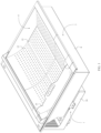
- FIG. 1 is a top-front-right perspective view of the present invention.
- FIG. 2 is top-rear-right perspective view of the present invention, wherein a divider of the food holding station is positioned centrally.
- FIG. 3 is a bottom-rear-right perspective view of the present invention.
- FIG. 4 is a front elevational view of the present invention.
- FIG. 5 is a sectional view of the present invention, taken along A-A′ of FIG. 4 .
- FIG. 6 is a detailed view of section 6 on FIG. 5 .
- FIG. 7 is an exploded top-rear-left perspective view of the present invention.
- FIG. 8 is an exploded bottom-rear-right perspective view of the present invention.
- the present invention is a hot food holding station.
- An objective of the present invention is to provide users with a device that can keep food warm and mess free, especially food that has been deep fried or cooked.
- the present invention intents to provide consumers convenience of serving heated ready-to-eat food with improved quality.
- the present invention further ensures that edibles that are being held within the food storage unit are evenly heated.
- the present invention uses a heated airflow system that comprises multiple air flow passages and a multi-functional grease tray ramp. Further, the present invention utilizes fresh air from the atmosphere for heating the food, thereby preventing recirculation of air within the system.
- the present invention is an efficient and improved design for a hot food holding station, that can maintain the quality and freshness of hot food, without creating a greasy surface.
- the hot food holding station comprises an air blower unit 1 , an airflow unit 2 , a heated air chamber 3 and a food holding compartment 4 .
- the air blower unit 1 , the airflow unit 2 and the heated air chamber 3 are used together to operate a heated airflow system of the present invention.
- the airflow unit 3 comprises a first air flow chamber 5 , a heater cartridge 6 and a second air flow chamber 7 .
- the heater cartridge 6 is connected between the first air flow chamber 5 and the second airflow chamber 7 , such that fresh air from the first air flow chamber 5 gets hot as it traverses through the heater cartridge 6 and reaches the second air flow chamber 7 .
- the start of the heated airflow system can be seen as the air entering the air blower unit 1 on the left.
- the job of the first airflow chamber 5 is to hold incoming air that is delivered by the air blower unit 1 .
- the first airflow chamber 5 is an air compression chamber as it compresses air into the heat cartridge 6 . After the air has been pushed through the air blower unit 1 and the first airflow chamber 5 , the air will now enter the heat cartridge 6 .
- the airflow unit 2 is connected between the air blower unit 1 and the heated air chamber 3 .
- the air blower unit 1 pushes the air through the outlet of the air blower unit 1 , the air initially arrives in the first airflow chamber 4 of the airflow unit 2 .
- the heated air chamber 3 is connected between the airflow unit 2 and the food holding compartment 4 , such that heated air reaches the food in the food holding compartment 4 through the heated air chamber 3 .
- the food holding compartment 4 comprises a rectangular frame with a curved bottom surface.
- the food holding compartment 4 may comprise any other shape, as long as the intents of the present invention are not altered.
- the heated air chamber 3 comprises a receptacle 8 , a chamber tray 9 , an airflow nozzle 10 , and an airflow distribution cap 11 .
- the receptacle 8 has a rectangular shape with a depth ranging a few inches.
- the receptacle 8 may comprise any other shape, as long as the objectives of the present invention are fulfilled.
- the chamber tray 9 , the airflow nozzle 10 , and the airflow distribution cap 11 enable uniform distribution and withholding of the hot air necessary for the smooth functioning of the present invention.
- the food holding compartment 4 comprises a plurality of apertures 12 . As seen in FIG. 1 and FIG. 2 , the plurality of apertures 12 is circular in shape.
- the plurality of apertures 12 may comprise any other size and shape, as long as the objectives of the present invention are fulfilled.
- the chamber tray 9 , the airflow nozzle 10 , and the airflow distribution cap 11 are positioned within the receptacle 8 .
- the airflow distribution cap 11 is mounted onto a lower surface 4 a of the food holding compartment 4 , such that the air distribution cap 11 distributes air within the heated air chamber 3 .
- the plurality of apertures 12 traverses through the food holding compartment 4 and the plurality of apertures 12 is distributed across the food holding compartment 4 . This arrangement enables hot air in the heated air chamber 3 to get to the foot holding compartment 4 in a uniform manner, thereby enabling even heating of the food in the food holding compartment 4 .
- the food holding compartment 4 is in fluid communication with the heated air chamber 3 through the plurality of apertures 12 , and the heated air chamber 3 is in fluid communication with the air flow unit 2 and the air blower unit 1 .
- the air blower unit 1 intakes atmospheric air into the device and transfers it through the air flow unit 2 .
- the air flow unit 2 compresses the air, makes it hot and sends it to the heated air chamber 3 .
- the airflow nozzle 10 is operably coupled to the air distribution cap 11 , such that the air distribution cap 11 distributes hot air coming through the airflow nozzle 10 within a space between the chamber tray 9 and the lower surface 4 a of the food holding compartment 4 .
- the components within the heated air chamber 3 distributes the hot air evenly within the heated air chamber 3 and passes the hot air into the food holding compartment 4 through the plurality of apertures 12 .
- the heat cartridge 6 is the component of the present invention that rises the temperature of the air flowing through the apparatus in order to maintain heat for the edibles being held by the present invention.
- the heater cartridge 6 comprises a casing 13 , an inlet section 14 , an outlet section 15 , and a heater 16 .
- the inlet section 14 is positioned opposite to the outlet section 15 across the casing 13
- the heater 16 is positioned within the casing 13 . This is so that the inlet section 14 directs air coming from the first airflow chamber 5 into the heater 16 to create heated air and then directs the heated air to the outlet section 15 .
- the inlet section 14 acts as a barrier that guide the incoming air into the casing 13 .
- the inlet section 14 acts as a funnel for incoming air that is led straight into the heater 16 .
- the inlet section 14 comprises a first flange 17 and a second flange 18
- the outlet section 15 comprises a first nozzle 19 and a second nozzle 20 .
- the first flange 17 is laterally offset from the second flange 18 in such a way that the first flange 17 and second flange 18 are wing-like attachments to one end of the heat cartridge 6 as shown in FIG. 6 .
- first flange 17 is located at a top end of the casing 13 and the second flange 18 is located at a bottom end of the casing 13 .
- first flange 17 and second flange 18 are the entrances for air coming into the heat cartridge 6 .
- the first flange 17 and second flange 18 are shaped as ramps on the ceiling and the base of the first airflow chamber 4 as shown in FIG. 6 .
- the first flange 17 and second flange 18 are tightly secured against the ceiling and base of the first airflow chamber 4 so that all the incoming air by means of the air blower unit will enter the heater 16 .
- the first flange 17 and the second flange 18 are angularly offset from the casing 13 , such that the first flange 17 and the second flange 18 are facing away from the heater 16 .
- the first nozzle 19 is laterally offset from the second nozzle 20 .
- the first nozzle 19 and second nozzle 20 are located opposite to the first flange 17 and second flange 18 across the casing 13 .
- the first nozzle 19 is located at the top end of the casing 13 and the second nozzle 20 is located at the bottom end of the casing 13 .
- first nozzle 19 and the second nozzle 20 are angularly offset from the casing 13 , such that the first nozzle 19 and the second nozzle 20 are facing towards the heater 16 inside the casing 13 .
- shape of the first nozzle 19 and second nozzle 20 is a variation of the first flange 17 and second flange 18 except that instead of the wings pointing outwards, the wings are concaving inwards. This is so that, the first nozzle 19 and second nozzle 20 are used to help direct the heated air coming from the heater 16 into the second airflow chamber 7 , thereby compressing the airflow against the trailing edge of the heating element and to restrict the airflow through the heater cartridge 6 .
- the second air flow chamber 7 comprises a grease tray 21 , wherein the grease tray 21 is connected between the outlet section 15 and the airflow nozzle 10 .
- the grease tray 21 serves two main purposes. The first purpose of holding excessive grease that is leaked off from the edibles being held warm at the food holding compartment 4 , and the second purpose of helping to guide the heated air towards the exit point of the apparatus in order to keep the edibles heated and warm.
- the grease tray 21 comprises a ramp 22 , a base 23 , and a plurality of barriers 24 .
- the ramp 22 comprises a first end 22 a , a second end 22 b , and a bent section 22 c , wherein the first end 22 a is positioned opposite to the second end 22 b across the ramp 22 .
- the bent section 22 c is positioned adjacent the second end 22 b
- the first end 22 a is mounted centrally across a width of the base 23
- the second end 22 b is mounted adjacent the airflow nozzle 10 .
- the ramp 22 begins in the base-center of a rectangular tray.
- the ramp 22 is angularly offset from the base 23 , such that the ramp 22 guides air coming from the outlet section 15 onto the airflow nozzle 10 .
- the ramp 22 angles upwards at an acute angle close to sixty to fifty degrees and straighten out ninety degrees up after reaching the airflow nozzle 10 .
- the ramp 22 reaches the airflow nozzle 10 , and the bent section 22 c is created that curl slightly inwards to help guide the air through the airflow nozzle 10 .
- the bent section 22 c further guides the heated air in the desired direction. As seen in FIG. 7 and FIG.
- the plurality of barriers 24 is perimetrically connected around the base 23 , and the plurality of barriers 24 is normally positioned across the base 23 .
- the base 23 is a rectangular-shaped tray that has barriers perpendicular to the base 23 along the perimeter. This is so that the base 23 and plurality of barriers 24 at the perimeter of this component act as a tray for excessive grease that has leaked from the edibles being held.
- the shape of the airflow nozzle 10 is such that, the airflow nozzle 10 is secured tightly with the grease tray 21 to ensure proper airflow through the apparatus.
- the chamber tray 9 comprises a first aperture 25
- the receptacle 8 comprises a second aperture 26 .
- the first aperture 25 traverses through the chamber tray 9 , and the first aperture 25 is positioned centrally across a length of the chamber tray 9 . This positioning and dimension of the first aperture 25 enables a perfect fit and smooth transition of the airflow nozzle 10 , and thus the heated air within the system.
- the second aperture 26 traverses through a bottom surface 8 a of the receptacle 8 .
- the first aperture 25 and the second aperture 26 are rectangular in shape.
- the first aperture 25 and the second aperture 26 may comprise any other shape and/or dimension, as long as the intents of the present invention are not altered.
- the receptacle 8 acts as the housing compartment for all the different components of the heated air chamber 3 , and thus the second aperture 26 is key for the transmission and transfer of air between the second air flow chamber 7 and the heated air chamber 3 .
- the chamber tray 9 is positioned between the airflow nozzle 10 and the air distribution cap 11 , such the airflow nozzle 10 is secured tightly along the first aperture 25 . Further, the chamber tray 9 delineates a bottom surface 3 a of the heated air chamber 3 , so that the chamber tray 9 bounds the heated air inside the apparatus underneath the food holding compartment 4 .
- the airflow nozzle 10 regulates the heated air that is going to the airflow distribution cap 11 .
- the airflow nozzle 10 comprises a body 27 and an air slit 28 .
- the body 27 comprises a roof 27 a and a plurality of walls 27 b , wherein the plurality of walls 27 b is positioned perimetrically around the roof 27 a .
- the airflow nozzle 10 has a long rectangular house-like shape, with an empty base that allows the heated air to go through the airflow nozzle 10 .
- the air slit 28 traverses centrally along a length of the roof 27 a .
- the airflow nozzle 10 has two angled walls that look like a roof attached to the long sides of the walls, wherein a small opening (the air slit) at the top allows heated air to go through the airflow nozzle 10 . Furthermore, the airflow nozzle 10 is pressed against the chamber tray 9 , and the air slit 28 is operably coupled to the air distribution cap 11 through the first aperture 25 . As previously mentioned, the airflow distribution cap 11 is attached under the food holding compartment 4 . Additionally, the shape and size of the air distribution cap 11 is equivalent to the airflow nozzle 10 as the airflow distribution cap 11 and airflow nozzle 10 are secured tightly against each other.
- the heated air passes through the airflow nozzle 10 , the heated air is compressed against the airflow distribution cap 11 and distributed to the heated air chamber 3 , which is the space beneath the food holding compartment 4 .
- the air distribution cap ensures even distribution of heated air across the heated air chamber 3 .
- the heated air chamber 3 is the compartment of the apparatus which contains the heated air that is distributed to the edibles on the food holding compartment 4 .
- the heated air chamber 3 further comprises a temperature probe 29 .
- the temperature probe 29 is positioned along a wall of the receptacle 8 .
- the temperature probe 29 may be positioned on any other location across the device, as long as the objectives of the present invention are fulfilled.
- the temperature probe 29 enables an accurate temperature control method as it reflects the temperature of the heated air chamber 3 . In other words, the temperature probe 29 will give knowledge of whether the temperature is acceptable or not within the apparatus.
- the air blower unit 1 comprises a base receptacle 30 , a suction motor 31 , a microcontroller 32 , and a power source 33 , wherein the suction motor 31 , the microcontroller 32 and the power source 33 being mounted within the base receptacle 30 . As seen in FIG.
- the base receptacle 30 constitutes the primary casing that holds the important electric and electronic components of the present invention in a closed and safe location.
- suction motor 31 is intended to draw air through openings on the base receptacle 30
- the microcontroller 32 is a processing device that manages the operation of the electrical components within the present invention.
- the power source 33 is also positioned within the base receptacle 30 isolated from hazards in the external environment.
- the power source 33 is a rechargeable battery, that is used to deliver electrical power to the microcontroller 32 and the suction motor 31 .
- any other source of power, or a combination power sources may be employed for the smooth functioning of the hot food holding station.
- the present invention may comprise at least one electrical connector 34 , which may be mounted onto a surface of the base receptacle 30 , for providing electrical connectivity between the power source 33 and an external power supply.
- the temperature probe 29 and the power source 33 are electronically connected to the microcontroller 32 , so as to enable the smooth functioning of the electric and electronic components of the present invention.
- the suction motor 31 induces a pressure differential that draws atmospheric air into the first air flow chamber 5 .
- the suction motor 31 may comprise any brand, size, or power, as long as the suction motor 31 fits within the dimensions of the base receptacle 30 and fulfills the intends of the present invention.
- the present invention comprises a divider 35 .
- the divider 35 is positioned within the food holding compartment 4 , wherein the divider 35 is laterally displaceable across a length of the food holding compartment 4 .
- the divider 35 can section the food holding compartment 4 into multiple compartments, thereby enabling to store more than one kind of food and thus user friendliness.
- the divider 35 divides the food holding compartment 4 into a plurality of compartments.
- the present invention may comprise any other components that may be needed for the smooth functioning or improved functionalities of the hot food holding station.
- the present invention is an efficient and improved design for a hot food holding station, that can maintain the quality and freshness of hot food, without creating a greasy surface.
Landscapes
- Engineering & Computer Science (AREA)
- Food Science & Technology (AREA)
- Chemical & Material Sciences (AREA)
- Combustion & Propulsion (AREA)
- Mechanical Engineering (AREA)
- General Engineering & Computer Science (AREA)
- Physics & Mathematics (AREA)
- Thermal Sciences (AREA)
- Baking, Grill, Roasting (AREA)
Abstract
Description
Claims (16)
Priority Applications (1)
| Application Number | Priority Date | Filing Date | Title |
|---|---|---|---|
| US17/126,885 US11793354B2 (en) | 2019-12-18 | 2020-12-18 | Hot food holding station with multi-functional ramp |
Applications Claiming Priority (2)
| Application Number | Priority Date | Filing Date | Title |
|---|---|---|---|
| US201962949684P | 2019-12-18 | 2019-12-18 | |
| US17/126,885 US11793354B2 (en) | 2019-12-18 | 2020-12-18 | Hot food holding station with multi-functional ramp |
Publications (2)
| Publication Number | Publication Date |
|---|---|
| US20210186259A1 US20210186259A1 (en) | 2021-06-24 |
| US11793354B2 true US11793354B2 (en) | 2023-10-24 |
Family
ID=76439489
Family Applications (1)
| Application Number | Title | Priority Date | Filing Date |
|---|---|---|---|
| US17/126,885 Active 2042-01-25 US11793354B2 (en) | 2019-12-18 | 2020-12-18 | Hot food holding station with multi-functional ramp |
Country Status (1)
| Country | Link |
|---|---|
| US (1) | US11793354B2 (en) |
Families Citing this family (1)
| Publication number | Priority date | Publication date | Assignee | Title |
|---|---|---|---|---|
| WO2025049932A1 (en) * | 2023-08-30 | 2025-03-06 | Cfa Properties, Inc. | Food holder for a food holding unit |
Citations (5)
| Publication number | Priority date | Publication date | Assignee | Title |
|---|---|---|---|---|
| US20010052207A1 (en) * | 2000-03-06 | 2001-12-20 | Robert Davis | Roofing ventilation systems and methods |
| US8624169B1 (en) * | 2004-10-07 | 2014-01-07 | Wally B. Sorenson | Electric grilling appliance |
| US20170079473A1 (en) * | 2014-06-10 | 2017-03-23 | Duke Manufacturing Co. | Oven for heating food |
| US20200367690A1 (en) * | 2019-05-22 | 2020-11-26 | MUGÜ, Inc. | Automated cooking system |
| US20210362634A1 (en) * | 2017-07-14 | 2021-11-25 | Magna Seating Inc | Duct attachment molded within a foam pad |
-
2020
- 2020-12-18 US US17/126,885 patent/US11793354B2/en active Active
Patent Citations (5)
| Publication number | Priority date | Publication date | Assignee | Title |
|---|---|---|---|---|
| US20010052207A1 (en) * | 2000-03-06 | 2001-12-20 | Robert Davis | Roofing ventilation systems and methods |
| US8624169B1 (en) * | 2004-10-07 | 2014-01-07 | Wally B. Sorenson | Electric grilling appliance |
| US20170079473A1 (en) * | 2014-06-10 | 2017-03-23 | Duke Manufacturing Co. | Oven for heating food |
| US20210362634A1 (en) * | 2017-07-14 | 2021-11-25 | Magna Seating Inc | Duct attachment molded within a foam pad |
| US20200367690A1 (en) * | 2019-05-22 | 2020-11-26 | MUGÜ, Inc. | Automated cooking system |
Also Published As
| Publication number | Publication date |
|---|---|
| US20210186259A1 (en) | 2021-06-24 |
Similar Documents
| Publication | Publication Date | Title |
|---|---|---|
| US20090250452A1 (en) | Steam Convection Oven | |
| US6073547A (en) | Food temperature maintenance apparatus | |
| AU2025217258A1 (en) | Cooking device and components thereof | |
| US7829823B2 (en) | Heated food storage and display cabinet | |
| US3724092A (en) | Portable hair dryer | |
| US7210402B2 (en) | Cooking apparatus | |
| US11793354B2 (en) | Hot food holding station with multi-functional ramp | |
| CN101825100A (en) | Fan assembly | |
| US6523458B1 (en) | Portable toast warmer | |
| US4751911A (en) | Portable warming oven | |
| US20180070768A1 (en) | Cooking device | |
| US6198076B1 (en) | Convection oven | |
| US3678844A (en) | Food cooking grill | |
| US10667636B1 (en) | Air conditioning lid for beverage containers | |
| US9149154B1 (en) | Apparatus for transiently holding cooked food in a warm condition pending service of the food for consumption | |
| US11369008B2 (en) | Heating device for spray bottles | |
| GB2574604A (en) | Attachment for a handheld appliance | |
| EP3725192B1 (en) | Device for storing food products at hot temperature | |
| US11503954B2 (en) | Cabinet with opposed air curtains | |
| CN107003004A (en) | heating cooker | |
| CN105874275A (en) | Heating cooker | |
| US20090064984A1 (en) | Oven having a uniform hot air flow in the preparation space | |
| US2458837A (en) | Lunch can | |
| CN218245667U (en) | Aerosol forming device and heat source partition structure of heating device thereof | |
| US3552379A (en) | Food package and heater therefor |
Legal Events
| Date | Code | Title | Description |
|---|---|---|---|
| AS | Assignment |
Owner name: H&K INTERNATIONAL, TEXAS Free format text: ASSIGNMENT OF ASSIGNORS INTEREST;ASSIGNOR:KRATZER, JAY MITCHELL;REEL/FRAME:054694/0878 Effective date: 20191213 |
|
| FEPP | Fee payment procedure |
Free format text: ENTITY STATUS SET TO UNDISCOUNTED (ORIGINAL EVENT CODE: BIG.); ENTITY STATUS OF PATENT OWNER: SMALL ENTITY |
|
| FEPP | Fee payment procedure |
Free format text: ENTITY STATUS SET TO SMALL (ORIGINAL EVENT CODE: SMAL); ENTITY STATUS OF PATENT OWNER: SMALL ENTITY |
|
| STPP | Information on status: patent application and granting procedure in general |
Free format text: APPLICATION DISPATCHED FROM PREEXAM, NOT YET DOCKETED |
|
| STPP | Information on status: patent application and granting procedure in general |
Free format text: DOCKETED NEW CASE - READY FOR EXAMINATION |
|
| STPP | Information on status: patent application and granting procedure in general |
Free format text: RESPONSE TO NON-FINAL OFFICE ACTION ENTERED AND FORWARDED TO EXAMINER |
|
| STPP | Information on status: patent application and granting procedure in general |
Free format text: NOTICE OF ALLOWANCE MAILED -- APPLICATION RECEIVED IN OFFICE OF PUBLICATIONS |
|
| STPP | Information on status: patent application and granting procedure in general |
Free format text: AWAITING TC RESP., ISSUE FEE NOT PAID |
|
| STPP | Information on status: patent application and granting procedure in general |
Free format text: NOTICE OF ALLOWANCE MAILED -- APPLICATION RECEIVED IN OFFICE OF PUBLICATIONS |
|
| STPP | Information on status: patent application and granting procedure in general |
Free format text: PUBLICATIONS -- ISSUE FEE PAYMENT RECEIVED |
|
| STPP | Information on status: patent application and granting procedure in general |
Free format text: PUBLICATIONS -- ISSUE FEE PAYMENT VERIFIED |
|
| STCF | Information on status: patent grant |
Free format text: PATENTED CASE |