US11791477B2 - Roll-to-roll SOFC manufacturing method and system - Google Patents
Roll-to-roll SOFC manufacturing method and system Download PDFInfo
- Publication number
- US11791477B2 US11791477B2 US17/118,261 US202017118261A US11791477B2 US 11791477 B2 US11791477 B2 US 11791477B2 US 202017118261 A US202017118261 A US 202017118261A US 11791477 B2 US11791477 B2 US 11791477B2
- Authority
- US
- United States
- Prior art keywords
- sofc
- layer
- laminate
- tape
- precursor
- Prior art date
- Legal status (The legal status is an assumption and is not a legal conclusion. Google has not performed a legal analysis and makes no representation as to the accuracy of the status listed.)
- Active
Links
- 238000004519 manufacturing process Methods 0.000 title claims abstract description 20
- 239000002243 precursor Substances 0.000 claims abstract description 128
- 239000000203 mixture Substances 0.000 claims abstract description 85
- 239000002131 composite material Substances 0.000 claims abstract description 66
- 238000003490 calendering Methods 0.000 claims abstract description 38
- 239000000446 fuel Substances 0.000 claims abstract description 33
- 239000007787 solid Substances 0.000 claims abstract description 26
- 239000010410 layer Substances 0.000 claims description 455
- 239000003792 electrolyte Substances 0.000 claims description 124
- 238000000034 method Methods 0.000 claims description 89
- 239000002002 slurry Substances 0.000 claims description 41
- 239000002346 layers by function Substances 0.000 claims description 34
- 238000003475 lamination Methods 0.000 claims description 27
- 239000011230 binding agent Substances 0.000 claims description 17
- 238000005245 sintering Methods 0.000 claims description 13
- 238000000151 deposition Methods 0.000 claims description 12
- 239000004372 Polyvinyl alcohol Substances 0.000 claims description 9
- 238000001035 drying Methods 0.000 claims description 9
- 229920002451 polyvinyl alcohol Polymers 0.000 claims description 9
- 229920002037 poly(vinyl butyral) polymer Polymers 0.000 claims description 8
- 238000007764 slot die coating Methods 0.000 claims description 8
- 238000010345 tape casting Methods 0.000 claims description 6
- 238000005520 cutting process Methods 0.000 claims description 4
- 238000007650 screen-printing Methods 0.000 claims description 4
- 229920002301 cellulose acetate Polymers 0.000 claims description 3
- 238000003618 dip coating Methods 0.000 claims description 3
- 229920001483 poly(ethyl methacrylate) polymer Polymers 0.000 claims description 3
- 238000007790 scraping Methods 0.000 claims description 3
- 239000010408 film Substances 0.000 description 68
- 230000008569 process Effects 0.000 description 34
- 239000000463 material Substances 0.000 description 29
- 229910052760 oxygen Inorganic materials 0.000 description 21
- 239000001301 oxygen Substances 0.000 description 21
- PXHVJJICTQNCMI-UHFFFAOYSA-N nickel Substances [Ni] PXHVJJICTQNCMI-UHFFFAOYSA-N 0.000 description 18
- 230000006835 compression Effects 0.000 description 16
- 238000007906 compression Methods 0.000 description 16
- 238000010030 laminating Methods 0.000 description 16
- QVGXLLKOCUKJST-UHFFFAOYSA-N atomic oxygen Chemical compound [O] QVGXLLKOCUKJST-UHFFFAOYSA-N 0.000 description 15
- 239000000919 ceramic Substances 0.000 description 15
- 229920002799 BoPET Polymers 0.000 description 13
- 239000005041 Mylar™ Substances 0.000 description 13
- -1 oxygen ion Chemical class 0.000 description 13
- 238000006243 chemical reaction Methods 0.000 description 12
- 230000007547 defect Effects 0.000 description 12
- 238000012360 testing method Methods 0.000 description 12
- CETPSERCERDGAM-UHFFFAOYSA-N ceric oxide Chemical compound O=[Ce]=O CETPSERCERDGAM-UHFFFAOYSA-N 0.000 description 11
- 229910000422 cerium(IV) oxide Inorganic materials 0.000 description 11
- 239000011195 cermet Substances 0.000 description 11
- 239000007784 solid electrolyte Substances 0.000 description 11
- 229910021526 gadolinium-doped ceria Inorganic materials 0.000 description 10
- 229910001233 yttria-stabilized zirconia Inorganic materials 0.000 description 10
- XEEYBQQBJWHFJM-UHFFFAOYSA-N iron Substances [Fe] XEEYBQQBJWHFJM-UHFFFAOYSA-N 0.000 description 9
- 229910052727 yttrium Inorganic materials 0.000 description 9
- UFHFLCQGNIYNRP-UHFFFAOYSA-N Hydrogen Chemical compound [H][H] UFHFLCQGNIYNRP-UHFFFAOYSA-N 0.000 description 8
- MCMNRKCIXSYSNV-UHFFFAOYSA-N Zirconium dioxide Chemical compound O=[Zr]=O MCMNRKCIXSYSNV-UHFFFAOYSA-N 0.000 description 8
- 229910052746 lanthanum Inorganic materials 0.000 description 8
- 229910052751 metal Inorganic materials 0.000 description 8
- 239000002184 metal Substances 0.000 description 8
- VNWKTOKETHGBQD-UHFFFAOYSA-N methane Chemical compound C VNWKTOKETHGBQD-UHFFFAOYSA-N 0.000 description 8
- 229910052759 nickel Inorganic materials 0.000 description 8
- 239000002356 single layer Substances 0.000 description 8
- 229910052688 Gadolinium Inorganic materials 0.000 description 7
- 229910052779 Neodymium Inorganic materials 0.000 description 7
- 229910052772 Samarium Inorganic materials 0.000 description 7
- 239000010949 copper Substances 0.000 description 7
- 229910052739 hydrogen Inorganic materials 0.000 description 7
- 239000001257 hydrogen Substances 0.000 description 7
- 239000010416 ion conductor Substances 0.000 description 7
- 238000001314 profilometry Methods 0.000 description 7
- 229910052777 Praseodymium Inorganic materials 0.000 description 6
- 239000011575 calcium Substances 0.000 description 6
- 239000004020 conductor Substances 0.000 description 6
- 239000002019 doping agent Substances 0.000 description 6
- 239000012528 membrane Substances 0.000 description 6
- 239000000126 substance Substances 0.000 description 6
- 239000000758 substrate Substances 0.000 description 6
- 229910000859 α-Fe Inorganic materials 0.000 description 6
- 229910052791 calcium Inorganic materials 0.000 description 5
- 239000011248 coating agent Substances 0.000 description 5
- 238000000576 coating method Methods 0.000 description 5
- 239000011777 magnesium Substances 0.000 description 5
- 238000005259 measurement Methods 0.000 description 5
- 229910052761 rare earth metal Inorganic materials 0.000 description 5
- 150000002910 rare earth metals Chemical class 0.000 description 5
- 230000002441 reversible effect Effects 0.000 description 5
- 229910052712 strontium Inorganic materials 0.000 description 5
- 239000010936 titanium Substances 0.000 description 5
- 229910052769 Ytterbium Inorganic materials 0.000 description 4
- 239000010406 cathode material Substances 0.000 description 4
- 229910010293 ceramic material Inorganic materials 0.000 description 4
- 229910052802 copper Inorganic materials 0.000 description 4
- 238000010586 diagram Methods 0.000 description 4
- 239000002270 dispersing agent Substances 0.000 description 4
- 230000000694 effects Effects 0.000 description 4
- 239000002001 electrolyte material Substances 0.000 description 4
- 239000011532 electronic conductor Substances 0.000 description 4
- 229910052742 iron Inorganic materials 0.000 description 4
- 229910052749 magnesium Inorganic materials 0.000 description 4
- 239000011533 mixed conductor Substances 0.000 description 4
- 239000004014 plasticizer Substances 0.000 description 4
- 229910052723 transition metal Inorganic materials 0.000 description 4
- 150000003624 transition metals Chemical class 0.000 description 4
- 229910052726 zirconium Inorganic materials 0.000 description 4
- 229910002449 CoO3−δ Inorganic materials 0.000 description 3
- YXFVVABEGXRONW-UHFFFAOYSA-N Toluene Chemical compound CC1=CC=CC=C1 YXFVVABEGXRONW-UHFFFAOYSA-N 0.000 description 3
- PACGUUNWTMTWCF-UHFFFAOYSA-N [Sr].[La] Chemical compound [Sr].[La] PACGUUNWTMTWCF-UHFFFAOYSA-N 0.000 description 3
- 150000001768 cations Chemical class 0.000 description 3
- KRKNYBCHXYNGOX-UHFFFAOYSA-N citric acid Chemical compound OC(=O)CC(O)(C(O)=O)CC(O)=O KRKNYBCHXYNGOX-UHFFFAOYSA-N 0.000 description 3
- 229910017052 cobalt Inorganic materials 0.000 description 3
- 239000010941 cobalt Substances 0.000 description 3
- GUTLYIVDDKVIGB-UHFFFAOYSA-N cobalt atom Chemical compound [Co] GUTLYIVDDKVIGB-UHFFFAOYSA-N 0.000 description 3
- 229910052963 cobaltite Inorganic materials 0.000 description 3
- 238000001514 detection method Methods 0.000 description 3
- 150000002500 ions Chemical class 0.000 description 3
- FZLIPJUXYLNCLC-UHFFFAOYSA-N lanthanum atom Chemical compound [La] FZLIPJUXYLNCLC-UHFFFAOYSA-N 0.000 description 3
- 229910052750 molybdenum Inorganic materials 0.000 description 3
- 229910052758 niobium Inorganic materials 0.000 description 3
- 230000003287 optical effect Effects 0.000 description 3
- 239000011148 porous material Substances 0.000 description 3
- 238000012545 processing Methods 0.000 description 3
- 230000001172 regenerating effect Effects 0.000 description 3
- 229910052706 scandium Inorganic materials 0.000 description 3
- 239000010935 stainless steel Substances 0.000 description 3
- 229910001220 stainless steel Inorganic materials 0.000 description 3
- 229910052719 titanium Inorganic materials 0.000 description 3
- XLYOFNOQVPJJNP-UHFFFAOYSA-N water Substances O XLYOFNOQVPJJNP-UHFFFAOYSA-N 0.000 description 3
- RUDFQVOCFDJEEF-UHFFFAOYSA-N yttrium(III) oxide Inorganic materials [O-2].[O-2].[O-2].[Y+3].[Y+3] RUDFQVOCFDJEEF-UHFFFAOYSA-N 0.000 description 3
- 229910002768 BaCo0.4Fe0.4Zr0.1Y0.1O3-δ Inorganic materials 0.000 description 2
- 229910002767 BaCo0.4Fe0.4Zr0.1Y0.1O3−δ Inorganic materials 0.000 description 2
- 229910002939 BaZr0.8Y0.2O3−δ Inorganic materials 0.000 description 2
- IRIAEXORFWYRCZ-UHFFFAOYSA-N Butylbenzyl phthalate Chemical compound CCCCOC(=O)C1=CC=CC=C1C(=O)OCC1=CC=CC=C1 IRIAEXORFWYRCZ-UHFFFAOYSA-N 0.000 description 2
- CURLTUGMZLYLDI-UHFFFAOYSA-N Carbon dioxide Chemical compound O=C=O CURLTUGMZLYLDI-UHFFFAOYSA-N 0.000 description 2
- UGFAIRIUMAVXCW-UHFFFAOYSA-N Carbon monoxide Chemical compound [O+]#[C-] UGFAIRIUMAVXCW-UHFFFAOYSA-N 0.000 description 2
- LFQSCWFLJHTTHZ-UHFFFAOYSA-N Ethanol Chemical compound CCO LFQSCWFLJHTTHZ-UHFFFAOYSA-N 0.000 description 2
- VGGSQFUCUMXWEO-UHFFFAOYSA-N Ethene Chemical compound C=C VGGSQFUCUMXWEO-UHFFFAOYSA-N 0.000 description 2
- 239000005977 Ethylene Substances 0.000 description 2
- 229910002287 La2Mo2O9 Inorganic materials 0.000 description 2
- 239000004809 Teflon Substances 0.000 description 2
- 229920006362 Teflon® Polymers 0.000 description 2
- WGLPBDUCMAPZCE-UHFFFAOYSA-N Trioxochromium Chemical compound O=[Cr](=O)=O WGLPBDUCMAPZCE-UHFFFAOYSA-N 0.000 description 2
- 150000001412 amines Chemical class 0.000 description 2
- 239000010405 anode material Substances 0.000 description 2
- 238000013459 approach Methods 0.000 description 2
- 229910052788 barium Inorganic materials 0.000 description 2
- 229910002091 carbon monoxide Inorganic materials 0.000 description 2
- 230000003197 catalytic effect Effects 0.000 description 2
- HSJPMRKMPBAUAU-UHFFFAOYSA-N cerium(3+);trinitrate Chemical compound [Ce+3].[O-][N+]([O-])=O.[O-][N+]([O-])=O.[O-][N+]([O-])=O HSJPMRKMPBAUAU-UHFFFAOYSA-N 0.000 description 2
- 230000008859 change Effects 0.000 description 2
- 238000005229 chemical vapour deposition Methods 0.000 description 2
- 229910000428 cobalt oxide Inorganic materials 0.000 description 2
- IVMYJDGYRUAWML-UHFFFAOYSA-N cobalt(ii) oxide Chemical compound [Co]=O IVMYJDGYRUAWML-UHFFFAOYSA-N 0.000 description 2
- 150000001875 compounds Chemical class 0.000 description 2
- 238000010276 construction Methods 0.000 description 2
- 238000013461 design Methods 0.000 description 2
- 230000005611 electricity Effects 0.000 description 2
- 239000007772 electrode material Substances 0.000 description 2
- 235000021323 fish oil Nutrition 0.000 description 2
- 230000006870 function Effects 0.000 description 2
- 239000007789 gas Substances 0.000 description 2
- 230000006872 improvement Effects 0.000 description 2
- 229910052738 indium Inorganic materials 0.000 description 2
- 230000007774 longterm Effects 0.000 description 2
- 229910052748 manganese Inorganic materials 0.000 description 2
- 239000011572 manganese Substances 0.000 description 2
- 229910000480 nickel oxide Inorganic materials 0.000 description 2
- GNRSAWUEBMWBQH-UHFFFAOYSA-N oxonickel Chemical compound [Ni]=O GNRSAWUEBMWBQH-UHFFFAOYSA-N 0.000 description 2
- 239000002245 particle Substances 0.000 description 2
- 229920003229 poly(methyl methacrylate) Polymers 0.000 description 2
- 239000004926 polymethyl methacrylate Substances 0.000 description 2
- 230000036647 reaction Effects 0.000 description 2
- 230000009467 reduction Effects 0.000 description 2
- 238000003860 storage Methods 0.000 description 2
- 230000009466 transformation Effects 0.000 description 2
- 239000001993 wax Substances 0.000 description 2
- IIZPXYDJLKNOIY-JXPKJXOSSA-N 1-palmitoyl-2-arachidonoyl-sn-glycero-3-phosphocholine Chemical compound CCCCCCCCCCCCCCCC(=O)OC[C@H](COP([O-])(=O)OCC[N+](C)(C)C)OC(=O)CCC\C=C/C\C=C/C\C=C/C\C=C/CCCCC IIZPXYDJLKNOIY-JXPKJXOSSA-N 0.000 description 1
- QTYLEXQVLJYJHT-UHFFFAOYSA-N 2-(2-fluorophenyl)-3-methylmorpholine Chemical compound CC1NCCOC1C1=CC=CC=C1F QTYLEXQVLJYJHT-UHFFFAOYSA-N 0.000 description 1
- CLXPYTBRAZHUFD-UHFFFAOYSA-N 2-(4-fluorophenyl)-3-methylmorpholine Chemical compound CC1NCCOC1C1=CC=C(F)C=C1 CLXPYTBRAZHUFD-UHFFFAOYSA-N 0.000 description 1
- 229910002080 8 mol% Y2O3 fully stabilized ZrO2 Inorganic materials 0.000 description 1
- 108700040193 Adenylosuccinate lyases Proteins 0.000 description 1
- 108700040066 Argininosuccinate lyases Proteins 0.000 description 1
- 229910002741 Ba0.5Sr0.5Co0.8Fe0.2O3-δ Inorganic materials 0.000 description 1
- 229910002742 Ba0.5Sr0.5Co0.8Fe0.2O3−δ Inorganic materials 0.000 description 1
- 229910003371 Ba2In2O5 Inorganic materials 0.000 description 1
- 229910002761 BaCeO3 Inorganic materials 0.000 description 1
- 241000273930 Brevoortia tyrannus Species 0.000 description 1
- OYPRJOBELJOOCE-UHFFFAOYSA-N Calcium Chemical compound [Ca] OYPRJOBELJOOCE-UHFFFAOYSA-N 0.000 description 1
- 229920000049 Carbon (fiber) Polymers 0.000 description 1
- 229910000975 Carbon steel Inorganic materials 0.000 description 1
- 229910002484 Ce0.9Gd0.1O1.95 Inorganic materials 0.000 description 1
- 229910002505 Co0.8Fe0.2 Inorganic materials 0.000 description 1
- OTMSDBZUPAUEDD-UHFFFAOYSA-N Ethane Chemical compound CC OTMSDBZUPAUEDD-UHFFFAOYSA-N 0.000 description 1
- 102100038353 Gremlin-2 Human genes 0.000 description 1
- 101001032861 Homo sapiens Gremlin-2 Proteins 0.000 description 1
- 229910002561 K2NiF4 Inorganic materials 0.000 description 1
- 229910002136 La0.6Sr0.4Co0.8Fe0.2O3−δ Inorganic materials 0.000 description 1
- 229910002321 LaFeO3 Inorganic materials 0.000 description 1
- 229910002331 LaGaO3 Inorganic materials 0.000 description 1
- ZOKXTWBITQBERF-UHFFFAOYSA-N Molybdenum Chemical compound [Mo] ZOKXTWBITQBERF-UHFFFAOYSA-N 0.000 description 1
- 239000002228 NASICON Substances 0.000 description 1
- 229910003249 Na3Zr2Si2PO12 Inorganic materials 0.000 description 1
- 229910019142 PO4 Inorganic materials 0.000 description 1
- 239000002202 Polyethylene glycol Substances 0.000 description 1
- 239000004743 Polypropylene Substances 0.000 description 1
- ATUOYWHBWRKTHZ-UHFFFAOYSA-N Propane Chemical compound CCC ATUOYWHBWRKTHZ-UHFFFAOYSA-N 0.000 description 1
- 229920001131 Pulp (paper) Polymers 0.000 description 1
- 229920002472 Starch Polymers 0.000 description 1
- 235000021355 Stearic acid Nutrition 0.000 description 1
- NINIDFKCEFEMDL-UHFFFAOYSA-N Sulfur Chemical compound [S] NINIDFKCEFEMDL-UHFFFAOYSA-N 0.000 description 1
- 229910010252 TiO3 Inorganic materials 0.000 description 1
- RTAQQCXQSZGOHL-UHFFFAOYSA-N Titanium Chemical compound [Ti] RTAQQCXQSZGOHL-UHFFFAOYSA-N 0.000 description 1
- ISWNJSHGUJYCFP-UHFFFAOYSA-N [Ce].[Sr] Chemical compound [Ce].[Sr] ISWNJSHGUJYCFP-UHFFFAOYSA-N 0.000 description 1
- JZMOMQOPNXIJMG-UHFFFAOYSA-N [Co].[Sr].[Ba] Chemical compound [Co].[Sr].[Ba] JZMOMQOPNXIJMG-UHFFFAOYSA-N 0.000 description 1
- QBYHSJRFOXINMH-UHFFFAOYSA-N [Co].[Sr].[La] Chemical compound [Co].[Sr].[La] QBYHSJRFOXINMH-UHFFFAOYSA-N 0.000 description 1
- RUSSALBHISRMQU-UHFFFAOYSA-N [Co].[Sr].[Pr] Chemical compound [Co].[Sr].[Pr] RUSSALBHISRMQU-UHFFFAOYSA-N 0.000 description 1
- LEMJVPWNQLQFLW-UHFFFAOYSA-N [La+3].[La+3].[O-][Cr]([O-])=O.[O-][Cr]([O-])=O.[O-][Cr]([O-])=O Chemical class [La+3].[La+3].[O-][Cr]([O-])=O.[O-][Cr]([O-])=O.[O-][Cr]([O-])=O LEMJVPWNQLQFLW-UHFFFAOYSA-N 0.000 description 1
- BQENXCOZCUHKRE-UHFFFAOYSA-N [La+3].[La+3].[O-][Mn]([O-])=O.[O-][Mn]([O-])=O.[O-][Mn]([O-])=O Chemical class [La+3].[La+3].[O-][Mn]([O-])=O.[O-][Mn]([O-])=O.[O-][Mn]([O-])=O BQENXCOZCUHKRE-UHFFFAOYSA-N 0.000 description 1
- XGPJPLXOIJRLJN-UHFFFAOYSA-N [Mn].[Sr].[La] Chemical compound [Mn].[Sr].[La] XGPJPLXOIJRLJN-UHFFFAOYSA-N 0.000 description 1
- FVROQKXVYSIMQV-UHFFFAOYSA-N [Sr+2].[La+3].[O-][Mn]([O-])=O Chemical compound [Sr+2].[La+3].[O-][Mn]([O-])=O FVROQKXVYSIMQV-UHFFFAOYSA-N 0.000 description 1
- UNPDDPPIJHUKSG-UHFFFAOYSA-N [Sr].[Sm] Chemical compound [Sr].[Sm] UNPDDPPIJHUKSG-UHFFFAOYSA-N 0.000 description 1
- 238000009825 accumulation Methods 0.000 description 1
- NIXOWILDQLNWCW-UHFFFAOYSA-N acrylic acid group Chemical group C(C=C)(=O)O NIXOWILDQLNWCW-UHFFFAOYSA-N 0.000 description 1
- 229910052782 aluminium Inorganic materials 0.000 description 1
- 238000004458 analytical method Methods 0.000 description 1
- 229910021523 barium zirconate Inorganic materials 0.000 description 1
- 230000008901 benefit Effects 0.000 description 1
- 229910000416 bismuth oxide Inorganic materials 0.000 description 1
- 229910052796 boron Inorganic materials 0.000 description 1
- 238000005219 brazing Methods 0.000 description 1
- 238000001354 calcination Methods 0.000 description 1
- ZFARUSOUMSKJOE-UHFFFAOYSA-N calcium dioxido(oxo)manganese lanthanum(3+) Chemical compound [Mn](=O)([O-])[O-].[Ca+2].[La+3] ZFARUSOUMSKJOE-UHFFFAOYSA-N 0.000 description 1
- ODINCKMPIJJUCX-UHFFFAOYSA-N calcium oxide Inorganic materials [Ca]=O ODINCKMPIJJUCX-UHFFFAOYSA-N 0.000 description 1
- 239000001569 carbon dioxide Substances 0.000 description 1
- 229910002092 carbon dioxide Inorganic materials 0.000 description 1
- 239000004917 carbon fiber Substances 0.000 description 1
- 239000010962 carbon steel Substances 0.000 description 1
- 238000005266 casting Methods 0.000 description 1
- 230000015556 catabolic process Effects 0.000 description 1
- 239000003054 catalyst Substances 0.000 description 1
- 229920002678 cellulose Polymers 0.000 description 1
- 239000001913 cellulose Substances 0.000 description 1
- 229910021525 ceramic electrolyte Inorganic materials 0.000 description 1
- 229910052804 chromium Inorganic materials 0.000 description 1
- 239000011651 chromium Substances 0.000 description 1
- 235000015165 citric acid Nutrition 0.000 description 1
- 238000004939 coking Methods 0.000 description 1
- 239000003086 colorant Substances 0.000 description 1
- 239000000470 constituent Substances 0.000 description 1
- 238000010924 continuous production Methods 0.000 description 1
- 230000001351 cycling effect Effects 0.000 description 1
- 230000007423 decrease Effects 0.000 description 1
- 238000006731 degradation reaction Methods 0.000 description 1
- 230000001419 dependent effect Effects 0.000 description 1
- 229910003460 diamond Inorganic materials 0.000 description 1
- 239000010432 diamond Substances 0.000 description 1
- TYIXMATWDRGMPF-UHFFFAOYSA-N dibismuth;oxygen(2-) Chemical compound [O-2].[O-2].[O-2].[Bi+3].[Bi+3] TYIXMATWDRGMPF-UHFFFAOYSA-N 0.000 description 1
- 238000002845 discoloration Methods 0.000 description 1
- 238000003487 electrochemical reaction Methods 0.000 description 1
- 238000005516 engineering process Methods 0.000 description 1
- 238000011156 evaluation Methods 0.000 description 1
- 230000002349 favourable effect Effects 0.000 description 1
- 239000000835 fiber Substances 0.000 description 1
- 239000011152 fibreglass Substances 0.000 description 1
- 239000011888 foil Substances 0.000 description 1
- LNTHITQWFMADLM-UHFFFAOYSA-N gallic acid Chemical compound OC(=O)C1=CC(O)=C(O)C(O)=C1 LNTHITQWFMADLM-UHFFFAOYSA-N 0.000 description 1
- 229910052733 gallium Inorganic materials 0.000 description 1
- 230000009477 glass transition Effects 0.000 description 1
- 150000002334 glycols Chemical class 0.000 description 1
- 229910052736 halogen Inorganic materials 0.000 description 1
- 150000002367 halogens Chemical class 0.000 description 1
- 230000008595 infiltration Effects 0.000 description 1
- 238000001764 infiltration Methods 0.000 description 1
- 238000011835 investigation Methods 0.000 description 1
- 229910002075 lanthanum strontium manganite Inorganic materials 0.000 description 1
- 229910052745 lead Inorganic materials 0.000 description 1
- 239000000787 lecithin Substances 0.000 description 1
- 229940067606 lecithin Drugs 0.000 description 1
- 235000010445 lecithin Nutrition 0.000 description 1
- 239000000395 magnesium oxide Substances 0.000 description 1
- CPLXHLVBOLITMK-UHFFFAOYSA-N magnesium oxide Inorganic materials [Mg]=O CPLXHLVBOLITMK-UHFFFAOYSA-N 0.000 description 1
- LFKMKZZIPDISEK-UHFFFAOYSA-L magnesium;4-carboxy-2,6-dihydroxyphenolate Chemical compound [Mg+2].OC1=CC(C([O-])=O)=CC(O)=C1O.OC1=CC(C([O-])=O)=CC(O)=C1O LFKMKZZIPDISEK-UHFFFAOYSA-L 0.000 description 1
- 150000002739 metals Chemical class 0.000 description 1
- 238000012986 modification Methods 0.000 description 1
- 230000004048 modification Effects 0.000 description 1
- 239000011733 molybdenum Substances 0.000 description 1
- 239000003345 natural gas Substances 0.000 description 1
- QIQXTHQIDYTFRH-UHFFFAOYSA-N octadecanoic acid Chemical compound CCCCCCCCCCCCCCCCCC(O)=O QIQXTHQIDYTFRH-UHFFFAOYSA-N 0.000 description 1
- OQCDKBAXFALNLD-UHFFFAOYSA-N octadecanoic acid Natural products CCCCCCCC(C)CCCCCCCCC(O)=O OQCDKBAXFALNLD-UHFFFAOYSA-N 0.000 description 1
- 238000000847 optical profilometry Methods 0.000 description 1
- 238000007254 oxidation reaction Methods 0.000 description 1
- 238000005691 oxidative coupling reaction Methods 0.000 description 1
- 230000037361 pathway Effects 0.000 description 1
- 239000010452 phosphate Substances 0.000 description 1
- 235000021317 phosphate Nutrition 0.000 description 1
- 125000005498 phthalate group Chemical class 0.000 description 1
- 229910052697 platinum Inorganic materials 0.000 description 1
- BASFCYQUMIYNBI-UHFFFAOYSA-N platinum Substances [Pt] BASFCYQUMIYNBI-UHFFFAOYSA-N 0.000 description 1
- 231100000572 poisoning Toxicity 0.000 description 1
- 230000000607 poisoning effect Effects 0.000 description 1
- 230000010287 polarization Effects 0.000 description 1
- 229920000728 polyester Polymers 0.000 description 1
- 229920001223 polyethylene glycol Polymers 0.000 description 1
- 229920005596 polymer binder Polymers 0.000 description 1
- 239000002491 polymer binding agent Substances 0.000 description 1
- 229920006254 polymer film Polymers 0.000 description 1
- 229920001155 polypropylene Polymers 0.000 description 1
- 229920001296 polysiloxane Polymers 0.000 description 1
- 229910001848 post-transition metal Inorganic materials 0.000 description 1
- 239000000843 powder Substances 0.000 description 1
- 238000003825 pressing Methods 0.000 description 1
- 238000012827 research and development Methods 0.000 description 1
- 238000005096 rolling process Methods 0.000 description 1
- 229910052707 ruthenium Inorganic materials 0.000 description 1
- KZUNJOHGWZRPMI-UHFFFAOYSA-N samarium atom Chemical compound [Sm] KZUNJOHGWZRPMI-UHFFFAOYSA-N 0.000 description 1
- 238000004626 scanning electron microscopy Methods 0.000 description 1
- 229920002545 silicone oil Polymers 0.000 description 1
- 229910001415 sodium ion Inorganic materials 0.000 description 1
- 239000002904 solvent Substances 0.000 description 1
- 238000000935 solvent evaporation Methods 0.000 description 1
- 239000007921 spray Substances 0.000 description 1
- 238000005507 spraying Methods 0.000 description 1
- 238000004544 sputter deposition Methods 0.000 description 1
- 229910002076 stabilized zirconia Inorganic materials 0.000 description 1
- 239000008107 starch Substances 0.000 description 1
- 235000019698 starch Nutrition 0.000 description 1
- 239000008117 stearic acid Substances 0.000 description 1
- CIOAGBVUUVVLOB-UHFFFAOYSA-N strontium atom Chemical compound [Sr] CIOAGBVUUVVLOB-UHFFFAOYSA-N 0.000 description 1
- IATRAKWUXMZMIY-UHFFFAOYSA-N strontium oxide Inorganic materials [O-2].[Sr+2] IATRAKWUXMZMIY-UHFFFAOYSA-N 0.000 description 1
- 229910052717 sulfur Inorganic materials 0.000 description 1
- 239000011593 sulfur Substances 0.000 description 1
- 230000000153 supplemental effect Effects 0.000 description 1
- 239000004094 surface-active agent Substances 0.000 description 1
- 229910052715 tantalum Inorganic materials 0.000 description 1
- 238000005382 thermal cycling Methods 0.000 description 1
- 238000007736 thin film deposition technique Methods 0.000 description 1
- JPJZHBHNQJPGSG-UHFFFAOYSA-N titanium;zirconium;tetrahydrate Chemical compound O.O.O.O.[Ti].[Zr] JPJZHBHNQJPGSG-UHFFFAOYSA-N 0.000 description 1
- 229910052721 tungsten Inorganic materials 0.000 description 1
- 238000009827 uniform distribution Methods 0.000 description 1
- 229910052720 vanadium Inorganic materials 0.000 description 1
- 125000000391 vinyl group Chemical group [H]C([*])=C([H])[H] 0.000 description 1
- 229920002554 vinyl polymer Polymers 0.000 description 1
- 238000003466 welding Methods 0.000 description 1
Images


Classifications
-
- H—ELECTRICITY
- H01—ELECTRIC ELEMENTS
- H01M—PROCESSES OR MEANS, e.g. BATTERIES, FOR THE DIRECT CONVERSION OF CHEMICAL ENERGY INTO ELECTRICAL ENERGY
- H01M8/00—Fuel cells; Manufacture thereof
- H01M8/10—Fuel cells with solid electrolytes
- H01M8/12—Fuel cells with solid electrolytes operating at high temperature, e.g. with stabilised ZrO2 electrolyte
- H01M8/124—Fuel cells with solid electrolytes operating at high temperature, e.g. with stabilised ZrO2 electrolyte characterised by the process of manufacturing or by the material of the electrolyte
-
- H—ELECTRICITY
- H01—ELECTRIC ELEMENTS
- H01M—PROCESSES OR MEANS, e.g. BATTERIES, FOR THE DIRECT CONVERSION OF CHEMICAL ENERGY INTO ELECTRICAL ENERGY
- H01M8/00—Fuel cells; Manufacture thereof
- H01M8/002—Shape, form of a fuel cell
- H01M8/004—Cylindrical, tubular or wound
-
- H—ELECTRICITY
- H01—ELECTRIC ELEMENTS
- H01M—PROCESSES OR MEANS, e.g. BATTERIES, FOR THE DIRECT CONVERSION OF CHEMICAL ENERGY INTO ELECTRICAL ENERGY
- H01M4/00—Electrodes
- H01M4/86—Inert electrodes with catalytic activity, e.g. for fuel cells
- H01M4/8605—Porous electrodes
-
- H—ELECTRICITY
- H01—ELECTRIC ELEMENTS
- H01M—PROCESSES OR MEANS, e.g. BATTERIES, FOR THE DIRECT CONVERSION OF CHEMICAL ENERGY INTO ELECTRICAL ENERGY
- H01M4/00—Electrodes
- H01M4/86—Inert electrodes with catalytic activity, e.g. for fuel cells
- H01M4/8605—Porous electrodes
- H01M4/8621—Porous electrodes containing only metallic or ceramic material, e.g. made by sintering or sputtering
-
- H—ELECTRICITY
- H01—ELECTRIC ELEMENTS
- H01M—PROCESSES OR MEANS, e.g. BATTERIES, FOR THE DIRECT CONVERSION OF CHEMICAL ENERGY INTO ELECTRICAL ENERGY
- H01M4/00—Electrodes
- H01M4/86—Inert electrodes with catalytic activity, e.g. for fuel cells
- H01M4/88—Processes of manufacture
- H01M4/8803—Supports for the deposition of the catalytic active composition
- H01M4/8814—Temporary supports, e.g. decal
-
- H—ELECTRICITY
- H01—ELECTRIC ELEMENTS
- H01M—PROCESSES OR MEANS, e.g. BATTERIES, FOR THE DIRECT CONVERSION OF CHEMICAL ENERGY INTO ELECTRICAL ENERGY
- H01M4/00—Electrodes
- H01M4/86—Inert electrodes with catalytic activity, e.g. for fuel cells
- H01M4/88—Processes of manufacture
- H01M4/8825—Methods for deposition of the catalytic active composition
- H01M4/8828—Coating with slurry or ink
- H01M4/8835—Screen printing
-
- H—ELECTRICITY
- H01—ELECTRIC ELEMENTS
- H01M—PROCESSES OR MEANS, e.g. BATTERIES, FOR THE DIRECT CONVERSION OF CHEMICAL ENERGY INTO ELECTRICAL ENERGY
- H01M4/00—Electrodes
- H01M4/86—Inert electrodes with catalytic activity, e.g. for fuel cells
- H01M4/88—Processes of manufacture
- H01M4/8825—Methods for deposition of the catalytic active composition
- H01M4/8857—Casting, e.g. tape casting, vacuum slip casting
-
- H—ELECTRICITY
- H01—ELECTRIC ELEMENTS
- H01M—PROCESSES OR MEANS, e.g. BATTERIES, FOR THE DIRECT CONVERSION OF CHEMICAL ENERGY INTO ELECTRICAL ENERGY
- H01M4/00—Electrodes
- H01M4/86—Inert electrodes with catalytic activity, e.g. for fuel cells
- H01M4/88—Processes of manufacture
- H01M4/8878—Treatment steps after deposition of the catalytic active composition or after shaping of the electrode being free-standing body
- H01M4/8882—Heat treatment, e.g. drying, baking
- H01M4/8885—Sintering or firing
- H01M4/8889—Cosintering or cofiring of a catalytic active layer with another type of layer
-
- H—ELECTRICITY
- H01—ELECTRIC ELEMENTS
- H01M—PROCESSES OR MEANS, e.g. BATTERIES, FOR THE DIRECT CONVERSION OF CHEMICAL ENERGY INTO ELECTRICAL ENERGY
- H01M4/00—Electrodes
- H01M4/86—Inert electrodes with catalytic activity, e.g. for fuel cells
- H01M4/88—Processes of manufacture
- H01M4/8878—Treatment steps after deposition of the catalytic active composition or after shaping of the electrode being free-standing body
- H01M4/8896—Pressing, rolling, calendering
-
- H—ELECTRICITY
- H01—ELECTRIC ELEMENTS
- H01M—PROCESSES OR MEANS, e.g. BATTERIES, FOR THE DIRECT CONVERSION OF CHEMICAL ENERGY INTO ELECTRICAL ENERGY
- H01M8/00—Fuel cells; Manufacture thereof
- H01M8/10—Fuel cells with solid electrolytes
- H01M8/12—Fuel cells with solid electrolytes operating at high temperature, e.g. with stabilised ZrO2 electrolyte
- H01M8/1213—Fuel cells with solid electrolytes operating at high temperature, e.g. with stabilised ZrO2 electrolyte characterised by the electrode/electrolyte combination or the supporting material
- H01M8/1226—Fuel cells with solid electrolytes operating at high temperature, e.g. with stabilised ZrO2 electrolyte characterised by the electrode/electrolyte combination or the supporting material characterised by the supporting layer
-
- H—ELECTRICITY
- H01—ELECTRIC ELEMENTS
- H01M—PROCESSES OR MEANS, e.g. BATTERIES, FOR THE DIRECT CONVERSION OF CHEMICAL ENERGY INTO ELECTRICAL ENERGY
- H01M8/00—Fuel cells; Manufacture thereof
- H01M8/10—Fuel cells with solid electrolytes
- H01M8/12—Fuel cells with solid electrolytes operating at high temperature, e.g. with stabilised ZrO2 electrolyte
- H01M8/124—Fuel cells with solid electrolytes operating at high temperature, e.g. with stabilised ZrO2 electrolyte characterised by the process of manufacturing or by the material of the electrolyte
- H01M8/1246—Fuel cells with solid electrolytes operating at high temperature, e.g. with stabilised ZrO2 electrolyte characterised by the process of manufacturing or by the material of the electrolyte the electrolyte consisting of oxides
-
- H—ELECTRICITY
- H01—ELECTRIC ELEMENTS
- H01M—PROCESSES OR MEANS, e.g. BATTERIES, FOR THE DIRECT CONVERSION OF CHEMICAL ENERGY INTO ELECTRICAL ENERGY
- H01M4/00—Electrodes
- H01M4/86—Inert electrodes with catalytic activity, e.g. for fuel cells
- H01M2004/8678—Inert electrodes with catalytic activity, e.g. for fuel cells characterised by the polarity
- H01M2004/8684—Negative electrodes
-
- H—ELECTRICITY
- H01—ELECTRIC ELEMENTS
- H01M—PROCESSES OR MEANS, e.g. BATTERIES, FOR THE DIRECT CONVERSION OF CHEMICAL ENERGY INTO ELECTRICAL ENERGY
- H01M8/00—Fuel cells; Manufacture thereof
- H01M8/10—Fuel cells with solid electrolytes
- H01M8/12—Fuel cells with solid electrolytes operating at high temperature, e.g. with stabilised ZrO2 electrolyte
- H01M2008/1293—Fuel cells with solid oxide electrolytes
-
- Y—GENERAL TAGGING OF NEW TECHNOLOGICAL DEVELOPMENTS; GENERAL TAGGING OF CROSS-SECTIONAL TECHNOLOGIES SPANNING OVER SEVERAL SECTIONS OF THE IPC; TECHNICAL SUBJECTS COVERED BY FORMER USPC CROSS-REFERENCE ART COLLECTIONS [XRACs] AND DIGESTS
- Y02—TECHNOLOGIES OR APPLICATIONS FOR MITIGATION OR ADAPTATION AGAINST CLIMATE CHANGE
- Y02E—REDUCTION OF GREENHOUSE GAS [GHG] EMISSIONS, RELATED TO ENERGY GENERATION, TRANSMISSION OR DISTRIBUTION
- Y02E60/00—Enabling technologies; Technologies with a potential or indirect contribution to GHG emissions mitigation
- Y02E60/30—Hydrogen technology
- Y02E60/50—Fuel cells
-
- Y—GENERAL TAGGING OF NEW TECHNOLOGICAL DEVELOPMENTS; GENERAL TAGGING OF CROSS-SECTIONAL TECHNOLOGIES SPANNING OVER SEVERAL SECTIONS OF THE IPC; TECHNICAL SUBJECTS COVERED BY FORMER USPC CROSS-REFERENCE ART COLLECTIONS [XRACs] AND DIGESTS
- Y02—TECHNOLOGIES OR APPLICATIONS FOR MITIGATION OR ADAPTATION AGAINST CLIMATE CHANGE
- Y02P—CLIMATE CHANGE MITIGATION TECHNOLOGIES IN THE PRODUCTION OR PROCESSING OF GOODS
- Y02P70/00—Climate change mitigation technologies in the production process for final industrial or consumer products
- Y02P70/50—Manufacturing or production processes characterised by the final manufactured product
Definitions
- the present invention relates to solid oxide fuel cells, and more particularly to methods and systems for manufacturing solid oxide fuel cells. It can also be applied to other solid-state electrochemical technologies, such as solid oxide electrolyzers (SOEC) and solid electrolyte membrane (SOM) reactors.
- SOEC solid oxide electrolyzers
- SOM solid electrolyte membrane
- a solid oxide fuel cell converts chemical fuel directly into electricity using an oxygen ion or proton conducting membrane, denoted the electrolyte.
- the electrolyte should be as thin as possible while retaining a uniform, dense structure (typically ⁇ 1-30 ⁇ m for an electrode supported SOFC, although the invention is useful for anode supported, electrolyte supported and cathode supported designs).
- Mechanical strength is provided to the thin membrane by supporting it on a support layer.
- a functional layer that provides high electrochemical activity is placed between the support and electrolyte layers.
- a method of making a solid oxide fuel cell can include the steps of:
- first SOFC layer laminate tape comprising a first SOFC layer composition attached to a flexible carrier film layer
- the first SOFC layer composition, the second SOFC layer composition, and the third SOFC layer composition can comprise, interchangeably, an anode support layer composition, an anode functional layer composition, and an electrolyte layer composition.
- the method can include the steps of:
- providing the first SOFC layer laminate tape comprises providing an anode support layer laminate tape comprising an anode support layer attached to a flexible support tape layer;
- providing the second SOFC layer laminate tape comprises providing an anode functional layer laminate tape comprising an anode functional layer attached to a flexible anode tape layer;
- providing the third SOFC layer laminate tape comprises providing an electrolyte layer laminate tape comprising an electrolyte layer attached to a flexible electrolyte tape layer;
- the method can include the step of removing the flexible carrier film from the composite SOFC precursor laminate.
- the method can include the step of applying a cathode layer to the composite SOFC precursor laminate to form a solid oxide fuel cell assembly.
- a solid oxide fuel cell can be constructed with the solid oxide fuel cell assembly.
- the method can further include the step of sintering the composite SOFC precursor laminate.
- the method can also include the step of providing an anode support layer laminate tape comprises the step of providing an anode support layer slurry, depositing the anode support layer slurry on a flexible support tape; and drying the anode support layer slurry to form the anode support layer precursor tape; and the step of providing an anode functional layer laminate tape comprises the steps of providing an anode functional layer slurry, depositing the anode functional layer slurry on a flexible anode tape, and drying the anode functional layer slurry to form the anode functional layer precursor tape; and the step of providing an electrolyte layer laminate tape comprises the steps of providing an electrolyte layer slurry, depositing the electrolyte layer slurry onto a flexible electrolyte tape, and drying the electrolyte layer slurry to form the electrolyte layer precursor tape.
- At least one of the first, second and third SOFC layer compositions can be deposited onto the flexible carrier film by at least on selected from the group consisting of slot die coating, dip coating, tape casting, and screen printing.
- At least one of the first, second and third SOFC layer compositions can comprise a binder.
- the binder can be at least one selected from the group consisting of polyvinyl butyral (PVB) and polyvinyl alcohol (PVA), polyethyl methacrylate, cellulose acetate, and polyvinyl alcohol.
- the removal of the flexible carrier film layer from one of the first SOFC layer laminate tape, the second SOFC layer laminate tape, and the third SOFC layer laminate tape can be performed by at least one selected from the group consisting of scraping and peeling.
- the roll-to-roll assembly line can have a line speed of between 0.1 to 20 m/min.
- the method can be performed at temperatures of between 0 to 250° C. After each lamination step the laminated layers can be calendered to reduce the thickness between 0.1-40%.
- the method can further comprise cutting the rolls of the SOFC precursor laminate into SOFC coupons, and sintering the SOFC coupons for a predetermined sintering-time interval over a predetermined sintering-temperature range.
- the SOFC precursor laminate can have a porosity of from 1% to 50%.
- the SOFC precursor laminate can have a porosity of from 1% to 40%.
- the SOFC precursor laminate can have a porosity of from 1% to 30%.
- the SOFC precursor laminate can have a porosity of from 1% to 20%.
- a method for fabricating rolls of a solid oxide fuel cell (SOFC) structure wherein the SOFC structure comprises a stack of N ⁇ 3 layers arranged in a particular sequence, and the N layers comprise support and functional anode layers, and at least one electrolyte layer, can include the steps of:
- a method for fabricating rolls of a solid oxide fuel cell (SOFC) structure wherein the SOFC structure comprises a stack of N ⁇ 3 layers arranged in a particular sequence, and the N layers comprise support and functional anode layers, and at least one electrolyte layer, can include the steps of:
- the method can include the operation of selectively laminating a roll of a single layer with another roll of a single layer is performed based on laminability of the layers, the operation of selectively laminating a roll of a single layer with another roll of a layer stack is performed based on laminability of the layer and layer stack, and the operation of selectively laminating a roll of a layer stack with another roll of another layer stack is performed based on laminability of the layer stacks.
- a solid oxide fuel cell (SOFC) structure can include an anode structure comprising one or more anode support layers, and one or more anode functional layers, and an electrolyte structure comprising at least one electrolyte layer.
- the anode functional layers can be stacked between the anode support layers and the electrolyte layer.
- the anode structure and the electrolyte structure can have porosities in the range of 1% to 50%.
- the SOFC structure can be configured as a roll.
- the SOFC structure can be configured as a coupon having a predetermined width and a predetermined length along directions perpendicular to the stack direction.
- An assembly for making an SOFC comprising:
- a first roll of a first SOFC layer laminate tape comprising a first SOFC layer composition attached to a flexible carrier film layer;
- a second roll of a second SOFC laminate tape comprising a second SOFC layer composition attached to a flexible carrier film layer;
- a third roll of a third SOFC layer laminate tape comprising a third SOFC layer composition attached to a flexible carrier film layer;
- first, second, and third rolls being positioned along a roll-to-roll assembly line
- a calender for reducing the thickness of the SOFC precursor laminate to a second thickness less than the first thickness
- a removal device for continuously removing one of the respective tape layers from the SOFC precursor laminate, the other of the tape layers of the SOFC precursor laminate remaining;
- positioning structure for positioning adjacent to one another the SOFC precursor laminate and the third SOFC layer laminate tape, with the respective tape layers facing outward, to create a composite SOFC precursor laminate comprising the SOFC precursor laminate and the third SOFC layer laminate tape, the composite SOFC precursor laminate having a first thickness;
- a calender for calendering the composite SOFC precursor laminate to reduce the first thickness to a second thickness less that the first thickness.
- a method of making a solid oxide fuel cell can include the steps of:
- first SOFC layer laminate tape comprising a first SOFC layer composition attached to a flexible carrier film layer
- FIG. 1 is a schematic illustration of a green SOFC laminate structure with anode supported configuration according to the invention.
- FIG. 2 is a schematic illustration of a process for making a SOFC green cell according to the invention.
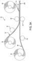
- FIG. 3 A is an enlargement of area FIG. 3 A in FIG. 2 ;
- FIG. 3 B is an enlargement of area FIG. 3 B in FIG. 2 ;
- FIG. 3 C is an enlargement of area FIG. 3 C in FIG. 2 .
- FIG. 4 is an enlargement of area FIG. 4 A in FIG. 2 ;
- FIG. 4 B is an enlargement of area FIG. 4 B in FIG. 2 ;
- FIG. 4 C is an enlargement of area FIG. 4 C in FIG. 2 ;
- FIG. 4 D is an enlargement of area FIG. 4 D in FIG. 2 ;
- FIG. 4 E is an enlargement of area FIG. 4 E in FIG. 2 ;
- FIG. 4 F is an enlargement of area FIG. 4 F in FIG. 2 .
- FIG. 5 is a schematic diagram of a slot die coating assembly and process.
- FIG. 6 is a schematic diagram of a tape casting assembly and process.
- FIG. 7 is a schematic diagram of an SOFC with an O 2 ⁇ permeable electrolyte.
- FIG. 8 is a schematic diagram of an SOFC with an H + permeable electrolyte.
- FIG. 9 A is a plot of roller temperature (° C.) vs speed (fpm) showing adhesion of electrolyte-electrolyte green tape layers for a calender gap of 130 microns
- FIG. 9 B is a plot of roller temperature (° C.) vs speed (fpm) for a calender gap of 153 microns
- FIG. 9 C is a plot of roller temperature (° C.) vs speed (fpm) for a calender gap of 172 microns.
- FIG. 10 A is a plot of roller temperature (° C.) vs speed (fpm) showing adhesion results for ASL-ASL green tape layers for a calender gap of 450 microns
- FIG. 10 B is a plot of roller temperature (° C.) vs speed (fpm) for a calender gap of 500 microns.
- FIG. 11 A is a plot of temperature (° C.) vs speed (fpm) showing adhesion of ASL-ASL green tape at higher roller temperatures for a calender gap of 254 microns;
- FIG. 11 B is a plot of roller temperature (° C.) vs speed (fpm) for a calender gap of 305 microns;
- FIG. 11 C is a plot of roller temperature (° C.) vs speed (fpm) for a calender gap of 380 microns.
- FIG. 12 A is a plot of roller temperature (° C.) vs speed (fpm) showing adhesion results for ASL-AFL green tape layers for a calender gap of 203 microns
- FIG. 12 B is a plot of roller temperature (° C.) vs speed (fpm) for a calender gap of 254 microns.
- FIG. 13 is a plot of roller temperature vs. calender gap (microns) illustrating 3-layer adhesion results, 3 layer damage results, and 2 layer adhesion results.
- FIG. 14 shows the plot of compression percentage vs. calender gap for the three set gap ranges used in Table 3.
- FIG. 15 A shows the optical and FIG. 15 B shows the profilometry images of the electrolyte surface of the medium gap cell used in SOFC testing.
- the profilometry image is magnified 9 kx in the out-of-plane direction to aid in defect detection.
- FIG. 16 A shows the optical image of the electrolyte surface of the small gap cell used in SOFC testing
- FIG. 16 B shows the profilometry images of the electrolyte surface of the small gap cell used in SOFC testing.
- the profilometry image is magnified 9 kx in the out-of-plane direction to aid in defect detection.
- FIG. 17 A shows the Optical profilometry images of the electrolyte surface of the large gap cell used in SOFC testing
- FIG. 17 B shows the profilometry image of the electrolyte surface of the large gap cell used in SOFC testing.
- the profilometry image is magnified 9 kx in the out-of-plane direction to aid in defect detection.
- FIG. 18 is a plot of voltage (V) and power density (W/cm 2 ) vs. current density (A/cm 2 ) for a medium gap SOFC measured at 650° C. after 150 h of operation.
- FIG. 19 is a plot of Re(Z)/ohm cm 2 vs time (hr) showing the total and ohmic ASR contributions to impedance measured at open circuit voltage (OCV) for the medium gap SOFC.
- FIG. 20 is a plot of Re(Z)/ohm cm 2 vs time (hr) showing the total and ohmic ASR contributions to impedance measured at OCV for the small gap SOFC.
- FIG. 21 is a plot of Re(Z)/ohm cm 2 vs time (hr) showing the total and ohmic ASR contributions to impedance measured at OCV for the large gap SOFC.
- FIG. 22 shows images of fractured cross-sections of post-tested SOFC cells for the small, medium, and large gap samples.
- SOFCs are utilized herein as exemplary devices in descriptions of embodiments of the present invention, but it should be understood that embodiments of the invention also encompass other types of solid-state electrochemical cells.
- a second type of solid-state electrochemical cell is known as a solid-oxide electrolyzer cell (SOEC), which resembles an SOFC that runs in reverse.
- SOEC takes electricity as an input to drive the reverse reaction of the SOFC, where water (and/or carbon dioxide) is converted into hydrogen (and/or carbon monoxide) at the fuel (or hydrogen) electrode and oxygen at the oxygen electrode.
- the oxygen electrode may also be called a steam electrode.
- the SOEC is an electrolytic cell involving the transformation of electrical energy into chemical energy
- the SOFC is a galvanic cell involving the transformation of chemical energy into electrical energy.
- the SOEC typically operates between 500° C. and 800° C. (or potentially as low as approximately 400° C.) and is a layered structure including, consisting essentially of, or consisting of a solid oxide (ceramic) electrolyte, a fuel electrode, and an oxygen electrode.
- the fuel electrode is the cathode
- the oxygen electrode is the anode.
- the most common electrolyte of SOECs is a dense ionic conductor that includes yttria stabilized zirconia (YSZ). Some other choices are scandia-stabilized zirconia (ScSZ), doped ceria-based electrolytes, or lanthanum gallate materials.
- the most common fuel-electrode material is a Ni-YSZ cermet.
- a cermet is a metal-ceramic composite material.
- Perovskite-type lanthanum strontium manganese (LSM) is one of the most common oxygen-electrode materials, though other materials are possible.
- SOECs may be planar or tubular just like SOFCs. SOEC electrolytes may also conduct protons rather than oxygen ions. Furthermore, the SOEC may in certain cases be exactly the same as the SOFC and used in both SOFC mode and SOEC mode. This is known as a reversible or regenerative fuel cell.
- a third type of solid-state electrochemical cell is known as solid oxide membrane (SOM) reactor, or an electrocatalytic reactor.
- the reactors have two chambers that are separated by a solid oxide, gas-tight ceramic electrolyte or membrane that is capable of transporting oxide ions (and/or protons) at elevated temperatures (typically between 600° C. and 1,000° C.).
- Such electrochemical cells may operate in electrolytic mode to convert input feedstock chemicals (e.g., CH 4 ) into other higher value chemicals (e.g., ethylene) and/or reactions may be driven through pressure or concentration gradients on either side of the membrane.
- Catalysts in each chamber may increase selectivity to a product by offering reaction sites and/or creating reaction pathways that are more favorable to certain products than others.
- SOM reactors have also been used to drive partial oxidation reactions of methane to form syngas (mostly hydrogen and carbon monoxide), oxidative coupling of methane (OCM) to form ethane and ethylene, and even the generation of high-purity oxygen from air.
- SOM reactors may be planar or tubular just like SOFCs.
- SOFCs solid oxide electrochemical cell devices other than SOFCs
- SOECs reversible or regenerative SOFCs
- SOMs electrocatalytic reactors
- references to SOFCs may be understood to include and encompass “SOECs”, reversible or regenerative SOFCs, “SOMs”, electrocatalytic reactors, or other solid-state electrochemical cells and related devices, unless otherwise indicated.
- a method of making a solid oxide fuel cell can include the steps of providing a first SOFC layer laminate tape comprising a first SOFC layer composition attached to a flexible carrier film layer, providing a second SOFC laminate tape comprising a second SOFC layer composition attached to a flexible carrier film layer, and providing a third SOFC layer laminate tape comprising a third SOFC layer composition attached to a flexible carrier film layer.
- the first SOFC layer laminate tape, the second SOFC layer laminate tape, and the third SOFC layer laminate tape are assembled on rolls positioned along a roll-to-roll assembly line.
- the method includes continuously positioning adjacent to one another and moving the first SOFC layer laminate tape, and the second SOFC layer laminate tape, with the respective flexible carrier film layers facing outward, to create a SOFC precursor laminate having a first thickness.
- the SOFC precursor laminate is passed through a calender to reduce the thickness of the SOFC precursor laminate to a second thickness less than the first thickness.
- One of the respective tape layers is continuously removed from the SOFC precursor laminate, the other of the tape layers of the SOFC precursor laminate remaining.
- the method includes continuously moving and positioning adjacent to one another the SOFC precursor laminate and the third SOFC layer laminate tape, with the respective tape layers facing outward, to create a composite SOFC precursor laminate comprising the SOFC precursor laminate and the third SOFC layer laminate tape, the composite SOFC precursor laminate having a first thickness.
- the composite SOFC precursor laminate is calendered to reduce the first thickness to a second thickness less than the first thickness.
- the first SOFC layer composition, the second SOFC layer composition, and the third SOFC layer composition can comprise, interchangeably, an anode support layer (ASL) composition, an anode functional layer (AFL) composition, and an electrolyte layer composition.
- ASL anode support layer
- AFL anode functional layer
- electrolyte layer composition an electrolyte layer composition
- the providing of the first SOFC layer laminate tape can comprise providing an ASL laminate tape comprising an ASL composition attached to a flexible support tape layer.
- the providing of the second SOFC layer laminate tape can comprise providing an AFL laminate tape comprising an AFL composition attached to a flexible anode tape layer.
- the providing of the third SOFC layer laminate tape can comprise providing an electrolyte layer laminate tape comprising an electrolyte layer composition attached to a flexible electrolyte tape layer.
- the ASL laminate tape, the AFL laminate tape, and the electrolyte layer laminate tape can be assembled on rolls or other supply devices positioned along a roll-to-roll or continuous assembly line.
- the method can include continuously positioning adjacent to one another and moving the AFL laminate tape, and one of the electrolyte layer laminate tape and the ASL laminate tape, with the respective flexible carrier film layers facing outward, to create an anode precursor laminate having a first thickness.
- the anode precursor laminate can be passed through a calender to reduce the thickness of the anode precursor laminate to a second thickness less than the first thickness.
- One of the respective flexible carrier film layers can be continuously removed from the anode precursor laminate, the other of the tape layers of the anode precursor laminate remaining.
- the method can include continuously moving and positioning adjacent to one another the anode precursor laminate, and the other of the electrolyte layer laminate tape and the ASL laminate tape, with the respective tape layers facing outward, to create a composite SOFC precursor laminate comprising the anode support layer, the anode functional layer, and the electrolyte layer, the composite SOFC precursor laminate having a first thickness.
- the composite SOFC precursor laminate can be calendered to reduce the first thickness to a second thickness less than the first thickness.
- the method can include the step of removing the remaining flexible carrier film from the composite SOFC precursor laminate.
- the method can further include the step of applying a cathode layer to the composite SOFC precursor laminate to form a SOFC assembly.
- the method can include the step of constructing a solid oxide fuel cell with the SOFC assembly.
- the method can include the step of providing an ASL laminate tape and can comprise the step of providing an ASL composition slurry, depositing the ASL composition slurry on a flexible support tape; and drying the ASL composition slurry to form the ASL laminate tape.
- the method can include the step of providing an AFL laminate tape and can comprise the steps of providing an AFL composition slurry, depositing the AFL composition slurry on a flexible carrier film, and drying the AFL composition slurry to form the AFL laminate tape.
- the AFL slurry in one embodiment consists of GDC, NiO, fish oil (dispersant), BBP-S-160 plasticizer, PVB-B-98 polyvinyl Butyral (binder), and ethanol and toluene (solvent).
- the step of providing an electrolyte layer laminate tape can comprise the steps of providing an electrolyte layer composition slurry, depositing the electrolyte layer composition slurry onto a flexible carrier film, and drying the electrolyte layer composition slurry to form the electrolyte layer laminate tape.
- At least one of the first, second and third SOFC layer compositions can be deposited onto the flexible carrier film by at least on selected from the group consisting of slot die coating, dip coating, tape casting, spray coating and screen printing.
- the material making the flexible carrier film also known as a carrier film or surface (i.e., a substrate for the SOFC layer), can be varied. Suitable materials include polymer films (e.g., mylar/polyester, Teflon, or polypropylene films), metal foils or belts (e.g., polished stainless steel carbon steel), various papers (e.g., wood pulp), or fiber mats (e.g., carbon fiber or fiberglass).
- the flexible carrier film should typically be flexible with appropriate mechanical strength for the roll-to-roll process. Such properties allow the flexible carrier film to adjust to slight differences in alignment (in the x-, y-, and/or z-axis) between different segments of the equipment used to deposit the SOFC layer compositions or laminate said layers together.
- the flexibility can allow for misalignments between segments of equipment varying from 1 micron to 5000 microns, or from 1 microns to 1000 microns, or even from 5 microns to 500 microns.
- the flexible carrier film should also typically have surface properties that allow the SOFC layer or layers to be easily peeled off, or released, from the flexible carrier film.
- the surface properties of the flexible carrier film can be enhanced with the use of a flexible carrier film having a coating, such as silicone (e.g., silicone oil), Teflon, lecithin, or waxes (e.g., parrafin wax).
- the flexible carrier film typically has a thickness between approximately 25 microns and approximately 400 microns, or approximately 25 microns to approximately 200 microns, or even approximately 50 microns to approximately 150 microns.
- the removal of the flexible carrier film layer from one of the first SOFC layer laminate tape, the second SOFC layer laminate tape, and the third SOFC layer laminate tape is performed by at least one selected from the group consisting of scraping and peeling.
- Such flexible carrier film removal processes may be initiated or assisted by the use of various tools, including blades and vacuum or suction devices. Other tape removal processes are possible.
- the line speed of the continuously moving or roll-to-roll assembly line can vary.
- the roll-to-roll assembly line can have a line speed of between approximately 0.1 to approximately 20 m/min.
- the roll-to-roll assembly may also have a line speed of between approximately 0.1 to approximately 15 m/min, or even a line speed between approximately 0.2 to approximately 12 m/min.
- the temperature at which the process is performed can vary.
- the method can be performed at temperatures of between 0 to 250° C. depending on the binder and plasticizer properties, such as glass transition temperature and solvent evaporation rate.
- the method can include the step of binder burn out and sintering the composite SOFC precursor laminate.
- the binder burnout temperature typically occurs between approximately 300° C. and 600° C.
- the sintering temperature can be from approximately 900° C. and approximately 1500° C., or between approximately 1100° C. and 1500° C., or even between approximately 1200° C. and approximately 1500° C.
- the extent of calendering can vary. After each lamination step the laminated layers are calendered to reduce the thickness between 0.1-40%.
- the extent of calendering after a lamination step can be 0.1, 0.2, 0.3, 0.4, 0.5, 0.6, 0.7, 0.8, 0.9, 1, 2, 3, 4, 5, 6, 7, 8, 9, 10, 11, 12, 13, 14, 15, 16, 17, 18, 19, 20, 21′, 22, 23, 24, 25, 26, 27, 28, 29, 30, 31, 32, 33, 34, 35, 36, 37, 38, 39, or 40%, or can be within a range of any high value and low value selected from these values.
- the term calendering as used herein also includes other suitable methods of applying pressure to the laminate to reduce the thickness.
- the calender gap is the distance between the two rollers.
- the calender gap can be between approximately 25 microns and approximately 600 microns, or approximately 50 microns and approximately 500 microns, or even approximately 75 microns and approximately 500 microns.
- the calender gap can spatially vary (i.e., be non-uniform), typically with variations of gap size of approximately ⁇ 1% to approximately 15% of the average gap thickness in the x-axis, y-axis, or z-axis of the calendar rollers.
- the method can further include cutting the rolls of the SOFC precursor laminate into SOFC coupons, and sintering the SOFC coupons for a predetermined sintering-time interval over a predetermined sintering-temperature range.
- the SOFC coupons may consist of a single, discrete SOFC, or a plurality of SOFCs (e.g., four SOFCs in a 2 by 2 array).
- the plurality of SOFCs can be singulated after sintering using a variety of methods, including the use of diamond saws or lasers for cutting.
- the SOFC precursor laminate can have a porosity of from 1% to 50%.
- the individual layers (ASL, AFL, electrolyte) comprising the SOFC precursor laminate can individually or collectively have a porosity of from 1, 2, 3, 4, 5, 6, 7, 8, 9, 10, 11, 12, 13, 14, 15, 16, 17, 18, 19, 20, 21, 22, 23, 24, 25, 26, 27, 28, 29, 30, 31, 32, 33, 34, 35, 36, 37, 38, 39, 40, 41, 42, 43, 44, 45, 46, 47, 48, 49 or 50%, or can have a porosity within a range of any high value and low value selected from these values.
- the SOFC precursor laminate can have a porosity from 1% to 40%.
- the SOFC precursor laminate can have a porosity of from 1% to 30%.
- the SOFC precursor laminate can have a porosity of from 1% to 20%.
- An assembly for making an SOFC can include a first roll of a first SOFC layer laminate tape comprising a first SOFC layer composition attached to a flexible carrier film layer, a second roll of a second SOFC laminate tape comprising a second SOFC layer composition attached to a flexible carrier film layer, and a third roll of a third SOFC layer laminate tape comprising a third SOFC layer composition attached to a flexible carrier film layer.
- the first, second, and third rolls can be positioned along a roll-to-roll assembly line.
- Positioning structure is provided for continuously positioning adjacent to one another and moving the first SOFC layer laminate tape, and the second SOFC layer laminate tape, with the respective flexible carrier film layers facing outward, to create a SOFC precursor laminate having a first thickness.
- a calender reduces the thickness of the SOFC precursor laminate to a second thickness less than the first thickness.
- a removal device is provided for continuously removing one of the respective tape layers from the SOFC precursor laminate, the other of the tape layers of the SOFC precursor laminate remaining.
- Positioning structure is provided for positioning adjacent to one another the SOFC precursor laminate and the third SOFC layer laminate tape, with the respective tape layers facing outward, to create a composite SOFC precursor laminate comprising the SOFC precursor laminate and the third SOFC layer laminate tape, the composite SOFC precursor laminate having a first thickness.
- a calender is provided for calendering the composite SOFC precursor laminate to reduce the first thickness to a second thickness less that the first thickness.
- the invention includes a method for fabricating rolls of a SOFC structure, wherein the SOFC structure comprises a stack of N ⁇ 3 layers arranged in a particular sequence, and the N layers comprise support and functional anode layers, and at least one electrolyte layer.
- the method includes:
- the invention can include a method for fabricating rolls of a SOFC structure, wherein the SOFC structure comprises a stack of N ⁇ 3 layers arranged in a particular sequence, and the N layers comprise support and functional anode layers, and at least one electrolyte layer.
- the method includes:
- the operation of selectively laminating a roll of a single layer with another roll of a single layer can be performed based on laminability, such as compressibility, robustness, adhesion strength to the adjacent layer, of the layers.
- laminability such as compressibility, robustness, adhesion strength to the adjacent layer, of the layers.
- a laminate with good laminability will result in a sintered SOFC which does not delaminate during sintering or subsequent normal operation as an SOFC device.
- the operation of selectively laminating a roll of a single layer with another roll of a layer stack is performed based on laminability of the layer and layer stack.
- the operation of selectively laminating a roll of a layer stack with another roll of another layer stack is performed based on laminability of the layer stacks.
- a solid oxide fuel cell (SOFC) structure may be anode supported, meaning that the anode support layer is the thickest portion of the device (i.e., the substrate), and which supports the other layers.
- the anode supported SOFC structure includes an anode structure comprising one or more anode support layers, and one or more anode functional layers; and an electrolyte structure comprising at least one electrolyte layer.
- the anode functional layers are stacked between the anode support layers and the electrolyte layer, and the anode structure and the electrolyte structure have porosities in the range of 1% to 50%.
- the SOFC structure can be configured as a roll.
- the SOFC structure can be configured as a coupon having a predetermined width and a predetermined length along directions perpendicular to the stack direction.
- LSM lanthan
- ferrites such as lanthanum ferrite (e.g., LaFeO 3 ), Sr-doped lanthanum ferrite (e.g., La 3.8 Sr 0.2 FeO 3 ), lanthanum strontium cobalt ferrite (LSCF, e.g., La 0.6 Sr 0.4 Co 0.8 Fe 0.2 O 3 ⁇ ), praseodymium strontium cobalt ferrite (PSCF, e.g., Pr 1 ⁇ x Sr x Co 0.8 Fe 0.2 O 3 ⁇ ), and barium strontium cobalt ferrite (BSCF, e.g., Ba 0.5 Sr 0.5 Co 0.8 Fe 0.2 O 3 ⁇ ); nickelates such as iron-doped nickelate (LNF, e.g., LaFe 1 ⁇ x Ni x O 3 ⁇ ) and Sr-doped LNF (LSNF); and cathode materials with the K 2 NiF 4 type
- LNF iron-doped nickelate
- the solid electrolyte is a dense ceramic material that conducts oxygen ions while minimizing electronic conduction therewithin in order to prevent current leakage and corresponding electrical losses.
- a solid electrolyte may also conduct protons (i.e., H + ions) or other types of ions (e.g., Na + ion conductors such as Na 3 Zr 2 Si 2 PO 12 , or NASICON).
- Electrolyte materials may be pure ion conductors, or they may be MIECs.
- the electrolyte may include, consist essentially of, or consist of multiple layers of different electrolyte materials (e.g., two different oxygen ion conductor layers, or an oxygen ion conductor layer and proton conductor layer).
- the thickness of the solid electrolyte may range from, for example, approximately 500 nm to approximately 40 ⁇ m, or 1 ⁇ m to approximately 40 ⁇ m, or 5 ⁇ m to approximately 30 ⁇ m, or even from approximately 10 ⁇ m to approximately 30 ⁇ m.
- the electrolyte includes, consists essentially of, or consists of, for example, one or more of the following proton conducting materials: BaCeO 3 and BaZrO 3 and varieties that are 1) doped with one or more of with one or more of Y, Sc, Nd, Gd, Yb, etc.
- the solid electrolyte includes, consists essentially of, or consists of, for example, various doped ceria materials such as samarium doped ceria (SDC, e.g., Ce 3.8 Sm 0.2 O 1.9 ) or gadolinium doped ceria (GDC, e.g., Ce 0.9 Gd 0.1 O 1.95 ).
- SDC samarium doped ceria
- GDC gadolinium doped ceria
- Such solid electrolytes may have dopant concentrations ranging from, for example, approximately 5 to approximately 30 mol %, or from approximately 10 to approximately 20 mol %.
- the solid electrolyte may include, consist essentially of, or consist of one or more doped cerias such as yttria-doped ceria (YDC, e.g., Y 0.1 Ce 0.9 O 1.95 ), neodymium-doped ceria (NdDC, e.g., Nd 0.1 Ce 0.9 O 1.95 ), praseodymium-doped ceria (PrDC, e.g., Pr 0.1 Ce 0.9 O 1.95 ), and/or lanthanum-doped ceria (LaDC, e.g., La 0.1 Ce 0.9 O 1.95 ).
- YDC yttria-doped ceria
- NdDC neodymium-doped ceria
- PrDC praseodymium-doped ceria
- LaDC lanthanum-doped ceria
- Such solid electrolytes may have dopant concentrations ranging from, for
- the cathode may include, consist essentially of, or consist of a composite material of one or more cathode materials and one or more electrolyte materials.
- the cathode may include, consist essentially of, or consist of a mixture of LSCF and GDC or SSC and GDC, e.g., in a ratio of approximately 3:7 to approximately 7:3 by mass.
- the cathode composite material may be both an ionic conductor and an electronic conductor, and the cathode may be porous to promote oxygen access for ionization and to provide electrochemically active triple phase boundaries (TPBs) where the electrolyte, air, and cathode meet.
- the cathode may have a porosity ranging from approximately 30% to approximately 60%, or from approximately 35% to approximately 55%, or even from approximately 40% to approximately 30%.
- the thickness of the cathode may be approximately 0.5 ⁇ m to approximately 500 ⁇ m, or approximately 5 ⁇ m to approximately 250 ⁇ m, or even approximately 10 ⁇ m to approximately 100 ⁇ m.
- CFL cathode functional layer
- the CFL may act to reduce the interfacial resistances between the cathode layer and electrolyte and/or to prevent undesirable reactions between the cathode layer and electrolyte that may occur during SOFC fabrication or operation.
- Such CFLs are generally fairly thin and may be approximately 1 nm to approximately 20 ⁇ m thick. The thickness of the CFL may also be between approximately 500 nm and approximately 10 ⁇ m or even between approximately 1 and approximately 5 ⁇ m.
- a CFL may include, consist essentially of, or consist of any combination of the materials described herein for the cathode (e.g, LSCF) and/or electrolyte layers (e.g., GDC), or less complex compounds featuring elements within such materials (e.g., cobalt or cobalt oxide).
- a CFL may also include, consist essentially of, or consist of a single cathode layer or electrolyte material.
- the anode may be a composite material, and is preferably a porous, ionic and electronic (i.e., electrons and/or holes) conductor in order to promote the electrochemical reaction.
- the anode includes, consists essentially of, or consists of a single phase or a composite material as a mixture, e.g., in a ratio of approximately 3:7 to approximately 7:3 by mass for a two-phase composite.
- any phase or all phases of anode may include, consist essentially of, or consist of, a MIEC material.
- any phase or all phases of anode may include, consist essentially of, or consist of, a pure electronic conductor or ionic conductor.
- the anode is a composite that includes, consists essentially of, or consists of cermet material.
- the anode is a cermet that includes, consists essentially of, or consists of, for example, various transition metals (e.g., Ni, Cu, Ti, Co, Mn, V, Mo, Nb, W, and/or Fe) mixed together as a composite with one or more solid electrolyte materials.
- the ceramic component of the composite cermet anode may include, consist essentially of, or consist of yttria stabilized zirconia (YSZ).
- the YSZ in the composite cermet anode may have dopant concentrations ranging from, for example, approximately 2 to approximately 20 mol %, or from approximately 3 to approximately 12 mol %.
- the YSZ includes 8 mol % Y (8YSZ, e.g., (ZrO 2 ) 0.92 (Y 2 O 3 ) 0.08 ) and/or 3 mol % Y (3YSZ, e.g., (ZrO 2 ) 0.97 (Y 2 O 3 ) 0.03 ).
- the anode includes, consists essentially of, or consists of, for example, a composite of Ni and YSZ (Ni-YSZ) or a composite of Cu and YSZ (Cu-YSZ).
- the ceramic component of a composite cermet anode includes, consists essentially of, or consists of, for example, GDC.
- the anode includes, consists essentially of, or consists of, for example, a composite of Ni and GDC (Ni-GDC) or a composite of Cu and GDC (Cu-GDC).
- Transition metal components in an anode cermet may exist as a ceramic (e.g., an oxide such as NiO) in an as-fabricated SOFC cell but transform into a metallic phase (e.g., Ni metal) in a reducing environment (e.g., a gas environment containing hydrogen gas).
- a ceramic e.g., an oxide such as NiO
- a metallic phase e.g., Ni metal
- a reducing environment e.g., a gas environment containing hydrogen gas.
- the anode may include, consist essentially of, or consist of a mixture of SFCM and another material such as ceria or GDC.
- the anode may be composed of an anode support and an anode functional layer.
- the anode support which supports the cell and allows gas (i.e., fuel) access to the functional layer, may include, consist essentially of, or consist of, e.g., a mixture of SFCM and ceria.
- the anode functional layer which promotes electrocatalytic activity in the anode, may include, consist essentially of, or consist of, e.g., a mixture of SFCM and GDC.
- the anode is free of nickel, nickel oxide, and/or yttria.
- the anode and/or portions thereof may be “all-ceramic,” i.e., free of nickel, nickel oxide, and other metals not incorporated within a ceramic-phase network. Such materials may exhibit superior performance and reliability during load following, thermal cycling, and redox cycling.
- the anode is further modified with the addition of one or more alkaline- and rare-earth materials (e.g., MgO, CaO, SrO and CeO 2 ) as an additional phase within the cermet or ceramic material.
- alkaline- and rare-earth materials e.g., MgO, CaO, SrO and CeO 2
- Other materials may “decorate” the surface of the anode and may be deposited via various techniques, such as an infiltrate solution (e.g., nickel or cerium nitrate) followed by calcination.
- Other deposition methods of the surface “decorating” materials include wash coating (e.g., a colloidal solution) and chemical vapor deposition (CVD).
- Additional infiltrate materials for anode include, consist essentially of, or consist of, for example, platinum group metals (e.g., Pt or Ru) and/or constituents from any of the other possible combinations of materials of the anode (e.g., Ni, Ce, Gd, Cu, Mg, Co, Pr, etc.).
- the anode may include, consist essentially of, or consist of an anode support (or anode support layer) and an anode functional layer (AFL).
- the AFL may include, consist essentially of, or consist of finer particles than in the ASL, thereby providing a higher number of triple phase boundaries and subsequent higher electrochemical activity.
- the AFL may act to reduce the interfacial resistances between the anode and electrolyte and/or to prevent undesirable reactions between the anode support layer and electrolyte that may occur during SOFC fabrication or operation.
- Such AFLs are generally fairly thin and in various embodiments AFL may be approximately 1 nm to approximately 20 ⁇ m thick.
- the thickness of AFL may be between approximately 500 nm and approximately 10 ⁇ m or even between approximately 1 and approximately 5 ⁇ m.
- An AFL may include, consist essentially of, or consist of any combination of the materials of the anode and/or electrolyte layers (e.g., Ni-GDC), or less complex compounds featuring elements within such materials (e.g., cobalt or cobalt oxide).
- the thickness of an anode support layer (ASL) may be approximately 100 ⁇ m to approximately 2,000 ⁇ m thick, or approximately 150 ⁇ m to approximately 1,000 ⁇ m, or approximately 200 ⁇ m to approximately 800 ⁇ m, or even approximately 350 ⁇ m to approximately 700 ⁇ m thick.
- the cell is electrolyte supported.
- the electrolyte is the thickest part of an electrolyte-supported cell.
- the anode and cathode are much thinner than the electrolyte in a cell that is electrolyte supported. While such cells tend to be stronger because the dense electrolyte is the thickest part of the cell, among other advantages, they tend to have greater ohmic losses and therefore the tradeoff is lower performance compared to electrode-supported (e.g., anode-supported) cells.
- the thickness of an electrolyte support layer may be approximately 75 ⁇ m to approximately 750 ⁇ m thick, or approximately 125 ⁇ m to approximately 500 ⁇ m, or even approximately 200 ⁇ m to approximately 350 ⁇ m thick.
- the electrolyte support layer in an electrolyte-supported cell may be thinner than an anode support layer in an anode-supported cell, e.g., due to the high density of typical electrolytes, whereas anodes are porous.
- the anode may have a thickness of approximately 5 ⁇ m to approximately 200 ⁇ m, or approximately 10 ⁇ m to approximately 100 ⁇ m, or even approximately 15 ⁇ m to approximately 50 ⁇ m.
- the cathode for an electrolyte-supported cell may have a thickness of approximately 0.5 ⁇ m to approximately 500 ⁇ m thick, or approximately 5 ⁇ m to approximately 250 ⁇ m, or even approximately 10 ⁇ m to approximately 100 ⁇ m thick.
- the cell is cathode supported.
- the cathode is the thickest part of a cathode-supported cell.
- the anode and electrolyte are much thinner than the cathode in a cell that is cathode-supported. While cathode-supported cells have been shown to have long lifetimes with low degradation, the tradeoff is that they tend to be more difficult to manufacture than electrolyte-supported cells or anode-supported cells, and they tend to have lower performance than anode-supported cells.
- the thickness of a cathode support layer may be approximately 125 ⁇ m to approximately 1,000 ⁇ m thick, or approximately 250 ⁇ m to approximately 800 ⁇ m, or even approximately 400 ⁇ m to approximately 600 ⁇ m thick.
- the anode may have a thickness of approximately 5 ⁇ m to approximately 200 ⁇ m, or approximately 10 ⁇ m to approximately 100 ⁇ m, or even approximately 15 ⁇ m to approximately 50 ⁇ m.
- the electrolyte may have a thickness that ranges from, for example, approximately 500 nm to approximately 40 ⁇ m, or 1 ⁇ m to approximately 40 ⁇ m, or 5 ⁇ m to approximately 30 ⁇ m, or even from approximately 10 ⁇ m to approximately 30 ⁇ m.
- the cell is metal supported or even ceramic supported.
- a metal-supported cell may include, consist essentially of, or consist of a metal support (e.g., a porous stainless steel such as 441 stainless steel) on which a thinner anode material (e.g., a cermet such as Ni-YSZ), electrolyte, and cathode are disposed.
- a thinner anode material e.g., a cermet such as Ni-YSZ
- electrolyte e.g., a cermet such as Ni-YSZ
- cathode e.g., cermet such as Ni-YSZ
- the thinner layers in such cells are often deposited using thin-film deposition techniques (e.g., sputtering or thermal/plasma spray techniques) to avoid undesirable reactions between the support and the other layers at high temperatures.
- a ceramic-supported cell may include a porous ceramic support (e.g., a YSZ or GDC scaffold), on which a thinner anode material (e.g., a cermet such as Ni-YSZ), electrolyte, and cathode are disposed. While supporting the cell, the porous ceramic support does not function as an anode.
- the porous ceramic support may be an electronically-conductive ceramic, or electronic conductivity may be introduced through infiltration of a conductive material (e.g., nickel) that coats all or a portion of the scaffold.
- an interconnect is used as the cell support, such that a separate interconnect is not needed in the SOFC stack.
- a porous metal-supported cell or ceramic-supported cell is joined to an interconnect (e.g., using brazing or welding).
- the metal, ceramic, or interconnect support may have a thickness of approximately 100 ⁇ m to approximately 5,000 ⁇ m, or approximately 150 ⁇ m to approximately 1,000 ⁇ m, or even approximately 200 ⁇ m to approximately 500 ⁇ m.
- the slurry should have uniform distribution of components, shear thinning behavior for casting purpose, and good wettability with a substrate on to which the slurry will be coated. This is achieved through the addition of various binders, plasticizers, and dispersing agents to the slurry in addition to the ceramic and/or metal components (e.g., powders also added to the slurry) or pore former components (e.g., starch, polymethyl methacrylate or PMMA, etc.) of a particular SOFC layer. Dispersing agents are also known as surfactants or deflocculants.
- Slurry binders may include vinyl-based (e.g., polyvinyl butyral), acrylic-based (e.g., polyethyl methacrylate), cellulose-based (e.g., cellulose acetate), and aqueous-based (e.g., polyvinyl alcohol) chemicals.
- Slurry plasticizers may include glycols (e.g., polyethylene glycol) or phthalates (e.g., n-butyl benzyl phthalate).
- Slurry dispersants may include blown menhaden fish oil, stearic acid, citric acid, phosphate ester, and various amines (e.g., polyoxyalkalene amine).
- the cathode design and material can vary.
- the cathode component of a SOFC functions as the site for electrochemical reduction of oxygen. It must have high electronic conductivity, electrochemical stability, high catalytic activity for oxygen reduction, matched thermal expansion coefficient with electrolyte and interconnect materials, and low cost.
- Typical cathode materials are perovskite-type oxide with a general formula ABO 3 where A are cations such as La, Sr, Ca, and Pb which are larger and coordinated to twelve oxygen anions, while the B are cations such as Ti, Cr, Ni, Fe, Co, and Zr which are smaller and coordinated to six oxygen anions.
- the cathode is usually coated onto an already sintered anode-electrolyte assembly through a coating technique such as screen printing followed by a sintering step that is appropriate for an SOFC.
- the cathode may alternatively be co-sintered with the anode and electrolyte.
- At least one of the first, second and third SOFC layer compositions can comprise a binder.
- a binder is an important component in fabricating the SOFC component. During green tape fabrication, the binder provides appropriate rheological properties to slurries for green tape fabrication and cohesion to components for good mechanical integrity. The binder is usually burned out during the subsequent sintering process. Along with other components, such as pore formers, the binder can affect the sintering conditions to reach desirable properties such as porosity, shrinkage rate, thermal expansion coefficient.
- the binder can be at least one selected from the group consisting of polyvinyl butyral (PVB) and polyvinyl alcohol (PVA). Other binders are possible.
- the green cell 10 is comprised of several layers which can vary, but for an anode-supported SOFC typically include an anode support layer (ASL) 78 , and anode functional layer (AFL) 118 , and an electrolyte layer 172 .
- the green cell 10 may also be known as a “half-cell” because the full SOFC will also have a cathode in addition to the anode and electrolyte.
- the ASL can be made up of several laminated layers as indicated by supplemental ASL 88 , which can represent n ⁇ 2 additional layers.
- FIG. 2 There is shown in FIG. 2 a system 30 that includes lamination sections configured in a roll-to-roll assembly line.
- the invention can be used with any number of lamination sections.
- the system 30 includes and ASL-ASL lamination section 34 , an ASL-AFL lamination section 38 , and a AFL-electrolyte lamination section 42 .
- the ASL-ASL lamination section 34 is shown in greater detail in FIG. 3 A and FIGS. 4 A-B.
- a roll 50 or other storage can be provided for a first ASL laminate tape 70 having a flexible carrier film 74 and a first ASL composition 78 joined to the flexible carrier film 74 .
- a roll 46 or other storage can be provided for a second ASL laminate tape 80 having a flexible carrier film 84 and a second ASL composition 88 joined to the flexible carrier film 84 .
- Rollers 52 and 54 can guide the first and second ASL laminate tapes to calenders 58 and 62 .
- the flexible carrier film 74 and flexible carrier film 84 face outward. As shown in FIG.
- the calenders 58 and 62 press the ASL composition 78 and second ASL composition 88 together.
- the thickness of the joined ASL layers is reduced from thickness AA-AA to thickness BB-BB.
- One of the flexible carrier film layer 74 and flexible carrier film layer 84 must be removed in order to laminate another SOFC laminate tape. This can be performed by any suitable process. As shown in FIG. 4 B, a scraper blade 92 can be positioned so as to scrape and remove the flexible carrier film layer 74 . The removed tape 74 accumulates on roller 66 . It is also possible to peel the flexible carrier film 74 onto the roller 66 where weak adhesion between the flexible carrier film 74 and the adjacent first ASL composition 78 permits. The SOFC precursor laminate 100 is thereby produced.
- the SOFC precursor laminate 100 then enters the ASL-AFL lamination zone 38 .
- an AFL laminate tape 114 can be provided on a roll 110 .
- the AFL laminate tape 114 has a flexible carrier film 122 and an AFL composition 118 adhered thereto.
- the AFL laminate tape 114 is guided by suitable structure such as roller 126 to a position adjacent the SOFC precursor laminate 100 , with the AFL composition 118 adjacent to the ASL composition 78 of the SOFC precursor laminate 100 .
- the AFL laminate tape 114 and SOFC precursor laminate 100 pass through calenders 130 and 132 in the direction shown by arrow 90 .
- the thickness of the combined SOFC layers —, the first ASL composition 78 , the second ASL composition 88 , and the AFL composition 118 is reduced from thickness CC-CC to thickness DD-DD.
- One of the flexible carrier film layers 122 and 84 can be removed by suitable structures such as scraper blade 140 as shown in FIG. 4 D .
- the collected flexible carrier film can be accumulated in a roll 144 .
- the anode precursor laminate 150 exits the ASL-AFL lamination zone 38 .
- the anode precursor laminate 150 then enters the electrolyte-anode precursor laminate lamination zone 42 , as shown in FIG. 3 C and FIGS. 4 E-F.
- the electrolyte layer laminate tape 164 can be provided on a roll or other suitable structure 160 .
- the electrolyte layer laminate tape 164 includes a flexible carrier film 168 and an electrolyte layer composition 172 adhered to the flexible carrier film 168 .
- the electrolyte layer laminate tape 164 can be guided by suitable structures such as roller 176 to calenders 180 and 182 .
- the calenders 180 and 182 reduce the thickness of the composite SOFC precursor laminate from the thickness EE-EE to thickness FF-FF as shown in FIG. 4 E as the tape moved in the direction shown by arrow 90 .
- the flexible carrier film layer 168 can be removed as by scraper blade 190 and collected on a roll 194 as shown in FIG. 4 F.
- the layers can be varied significantly. For example, it is possible to begin with the electrolyte layer and add the AFL layer and subsequently the ASL layer. Other orders of lamination are possible. For example, when AFL or electrolyte tapes are below a critical thickness (e.g., ⁇ 20 microns), removing the carrier film from a thin tape is very difficult and should be done only after the AFL is laminated. In other words, a thin AFL is preferably not laminated to a thin electrolyte layer because when attempting to remove the carrier film it can rip the thin tapes. However, with a proper release coating on the carrier film or dependent upon the release properties of the tape this may not be as critical.
- a critical thickness e.g., ⁇ 20 microns
- the SOFC layer compositions can be applied to the flexible carrier film by any suitable process.
- FIG. 5 a slot die coating process in which the SOFC layer composition is applied by a slot die coater 220 having a die body 224 .
- the SOFC layer composition slurry 232 is supplied to slot 228 as shown by arrow 236 .
- the slot 228 has a thickness 254 and deposits a portion 240 of the slurry composition 232 to the flexible carrier film surface 222 .
- the distance between the die body 224 and the flexible carrier film 222 allows for a gap 258 for the accumulation of the portion 240 of the slurry composition 232 .
- a coating 248 is deposited having a thickness shown by arrow 250 - 252 .
- the SOFC layer composition can be applied to the flexible carrier film by other processes.
- a tape casting process and apparatus 260 is shown in FIG. 6 .
- the SOFC layer composition 264 is supplied in the direction of arrow 262 to a reservoir 274 .
- a doctor blade 278 leaves a gap between the flexible carrier film 266 and the doctor blade 278 , such that upon movement of the flexible carrier film 266 in the direction shown by arrow 268 a layer of SOFC slurry composition 272 is deposited at a thickness shown by arrows 270 - 274 .
- Rollers 280 can be provided to facilitate movement of the flexible carrier film 266 .
- the composite SOFC laminate tape is then used to make SOFC 300 .
- the SOFC 300 (also known as an SOFC stack) can have a housing 310 which contains the composite SOFC including the first ASL 78 , the second (or additional) ASL 88 , the AFL 118 , the electrolyte layer 172 , and also a cathode 304 , as shown in FIG. 7 .
- the housing 310 is also known as a stack or a series of stack repeat units, which may include, consist essentially of, or consist of the composite SOFC, a conductive interconnect, and one or more seals (or gaskets) disposed between the composite SOFC and adjoining conductive interconnects.
- the interconnects provide a conductive path for electrons and fluidically separate cathode and anode sides of the composite SOFC. See for example U.S. Ser. No. 16/680,699 (Stack Configurations for Solid Oxide Electrochemical Cells) and U.S. Ser. No. 16/680,701 (Solid-State Electrochemical Devices Having Coated Components) filed Nov. 12, 2019, the disclosure of which are incorporated fully by reference.
- the electrolyte 172 shown in FIG. 7 is O 2 ⁇ permeable.
- Oxygen enters the SOFC through an inlet 314 and exits at an oxygen exit 318 .
- Hydrogen enters through an inlet 322 and exits through a hydrogen exit 326 which can also serve as an exit for the water product of the fuel-cell reaction.
- electron flow is generated and passes through line 330 and load 334 .
- the composite SOFC laminate tape can also be used to make SOFC 400 which uses a H + permeable electrolyte.
- the SOFC 400 can have a housing 410 which contains the composite SOFC including the first ASL 478 , the second (or additional) ASL 488 , the AFL 418 , the electrolyte layer 472 , and also a cathode 404 , as shown in FIG. 8 .
- the electrolyte 472 shown in FIG. 8 is H + permeable.
- Oxygen enters the SOFC through an inlet 414 and exits at an oxygen exit 418 which can also serve as the exit or the water product of the fuel-cell reaction.
- Hydrogen enters through an inlet 422 and exits through a hydrogen exit 426 . In the process of the reaction electron flow is generated and passes through line 430 and load 434 .
- the calendering process presses individual layers together between rollers to adhere them together.
- the process involves heat and high pressure to push the layers in intimate contact and promote adhesion between the polymer binders used in each green layer.
- An example of the calendering process used to make the structure in FIG. 1 from feeds of green tape is shown in FIG. 2 . From left to right, green tape of the two ASLs are fed to the first calender rollers and squeezed together to form one multi-layer. The green tapes are all supported on Mylar, which is removed after the first calender step from the top side, so that the next layer composed of AFL can be pressed against the ASL multilayer in calender step 2 .
- the process continues with the final electrolyte (such as Gd-doped ceria (GDC)) layer being applied to create the final SOFC multi-layer structure.
- GDC Gd-doped ceria
- the substrate can be a sheet of Mylar, or another layer of material, such as one of the tapes above.
- the electrolyte layer GDC
- the electrolyte layer is deposited on a sheet of Mylar with slot-die coating, dried, and then a layer of AFL is deposited on the dried electrolyte layer, and then this multilayer is dried.
- This multilayer can then be fed to the calendering process to calender it to fabricate the final multilayer structure.
- slot-die coating is a continuous process and can be introduced into the overall process to manufacture the green SOFC laminate in a roll-to-roll fashion.
- FIGS. 9 A- 9 C show calendering conditions of feed rate, gap, and temperature. The adhesion was most impacted by temperature and gap size, where a large gap size of 170 ⁇ m and low temperature of 90° C. did not result in adhesion, almost irrespective of feed rate, as shown by the figure. Higher temperatures, or smaller gap size, showed good adhesion.
- FIGS. 11 A- 11 C show that Smaller gaps of 254, 305, and 380 ⁇ m yielded good adhesion for faster feed rates (6-12 fpm), in several cases using higher temperature, as shown by FIGS. 11 A- 11 C. Not shown is data for a 450 ⁇ m gap at 150° C. and 6 fpm feed rate that exhibited poor adhesion. Compression amounts ranged from 4-8% for good adhesion under these conditions, with 3% showing poor adhesion. These results indicate that at higher temperature, better adhesion can be obtained with less amount of compression. Also, the amount of compression is reduced for faster feed rates, meaning for high throughput, the calendering operation would likely be pursued at higher temperatures and with smaller gap size.
- AFL and ASL layers were calendered top-to-top. Adhesion was found to be good for all but one studied case, as shown by FIGS. 12 A and 12 B . Good adhesion was obtained for compression amounts of 4.5% up to the maximum of 10.4% (denoted high compression in the figure).
- FIG. 13 is a plot of temperature vs. calender gap (microns) illustrating 3-layer adhesion results, 3 layer damage results, and 2 layer adhesion results. All tested conditions, except for the smaller gap on the tri-layer fabrication (380 ⁇ m), resulted in good adhesion of the laminate.
- the ASL-AFL lamination resulted in a compression of ⁇ 3%, while the ASL-ASL-AFL lamination step resulted in a compression of ⁇ 7%.
- This measurement found a lower limit to the set gap during ASL-ASL-AFL lamination of >380 ⁇ m to good adhesion.
- Measurements were performed on samples that were ⁇ 1.5 in. ⁇ 3 in. in size. 6-7 in. long strips ⁇ 2 in. long were fabricated to evaluate consistency along the length of a ⁇ 6 in. laminate needed to make the SOFC. The speed was also reduced to 4 fpm while the temperature was maintained at 140° C.
- the calendering of 4-layers (ASL to ASL to AFL to electrolyte) for full-size SOFC laminates was also tested.
- the optimal conditions to ensure adhesion and minimal laminate deformation were developed with test samples in the previous section.
- 6 in. ⁇ 6 in. 4-layer SOFC laminates are fabricated for sintering and SOFC testing.
- the set gap has a range that reports the minimum to maximum set gap across the much wider laminates.
- the ASL-AFL lamination to ASL step in the calendering process was considered to be the most important variable to modify, so three different set gap ranges were explored.
- the compression percentages and final thicknesses of the green laminates are shown graphically in FIG. 14 . As set gap size decreases, the compression percentage increases, as expected.
- the medium gap sample had the smallest average final thickness. This difference appears to result from a greater degree of compression during the first lamination step (ASL to AFL), even though the same set gap was used, and likely indicates a large variable in the manual process of lamination used.
- Optical images and profilometry of the SOFC tested cells are shown for medium ( FIG. 15 ), small ( FIG. 16 ), and large ( FIG. 17 ) gap samples.
- medium FIG. 15
- small FIG. 16
- large FIG. 17
- the range of heights shown for each height profile are the same, and the medium gap sample is a 4 cm ⁇ 4 cm sample, while the small and large gap samples are 5 cm ⁇ 5 cm samples.
- Each sample exhibits some impressions on the surface, with the vertical line processing defects most visible for the small gap sample.
- the small and large gap samples appear to generally suffer from the largest number of defects (in contrast to the full half-cell images above because of the area from which the laser cut cell was taken from), though, as will be shown later, the small and medium gap samples exhibit the best SOFC electrochemical performance, indicating robustness against observable defects. It is also worth noting that while these cells exhibit a greater level of defects, as observed by the metrology here, the defect concentration and type (except for the line defects) is not exceptionally worse than industrial cells made using conventional (i.e., not roll-to-roll) techniques. This indicates that the calendering process, with more improvement, should be able to replicate the level of defects in the standard processing route.
- a voltage and power density curve for the medium gap SOFC measured at 650° C. after 150 h of operation is shown in FIG. 18 .
- the OCV ⁇ 0.78 V
- the OCV is lower than a typical cell of the utilized SOFC structure, but is, in part, expected for the thinner GDC electrolyte layer used in the calendering trials. Additionally, defects, such as pinholes or cracks (possibly exacerbated by the horizontal and vertical lines described above), that may be introduced during calendering would further lower OCV. Moving to a thicker electrolyte and improved calendering process, or the slot die process discussed later, are expected to aid in increasing OCV and power density of the SOFC. Despite the lower OCV, the area-specific-resistance (ASR) is comparable to standard cells of the utilized SOFC structure (described below), and thus the power densities are not significantly lower than in the standard cell.
- ASR area-specific-resistance
- the area specific resistance (ASR) for the SOFC shown is in FIG. 19 .
- the ohmic contribution to impedance (assumed to be the high frequency x-axis intercept in a Nyquist plot, as commonly done) is shown by the lower line, and is approximately 0.08 ⁇ -cm 2 .
- the total ASR is ⁇ 0.19 ⁇ -cm 2 , meaning the electrode impedance is ⁇ 0.11 ⁇ -cm 2 .
- Additional ASR curves are shown for the small ( FIG. 20 ) and large FIG. 21 ) gap samples.
- the ohmic ASR is about 0.11-0.13 ⁇ -cm 2 , larger than the medium gap sample.
- the electrode impedance at 150 h is 0.11 and 0.13 ⁇ -cm 2 for the small and large gap samples, respectively, which is the same or larger than the medium gap sample.
- the medium gap sample processing conditions are the best, as they yield the lowest ASR. All samples showed similar OCV values of 0.78 and 0.785 V for small and large gap samples, respectively.
- the small gap sample is very similar to the medium gap sample in performance and thus should not be ruled out immediately for further testing in future work.
- the long-term performance was also stable for the SOFC measurement up to ⁇ 700 h, as shown for the large gap sample in FIG. 21 .
- the total and ohmic ASR contributions exhibit very little to no measurable change in value. This indicates the calendering process does not impact the long-term performance of the cells up to the measured conditions shown here.
- the small and medium gap tests were not evaluated beyond ⁇ 150-300 h due to limited test stand availability for this evaluation project.
- Post-test microstructure images from scanning electron microscopy are shown in FIG. 22 .
- Evidence for ASL-AFL poor adhesion during lamination is observed for the medium gap sample, but not in the small or large gap samples.
- Excellent lamination between electrolyte and AFL layers is observed for all samples in the images.
- the cell electrochemical performance was the best of the three.
- Other areas of the sample showed good lamination quality.
- a more detailed analysis of adhesion across a much larger area of the sample than found in a cursory SEM investigation would be needed.
- the good adhesion observed between layers for the majority of the samples shows excellent promise for this manufacturing process.
Landscapes
- Engineering & Computer Science (AREA)
- Chemical & Material Sciences (AREA)
- Chemical Kinetics & Catalysis (AREA)
- Manufacturing & Machinery (AREA)
- General Chemical & Material Sciences (AREA)
- Electrochemistry (AREA)
- Sustainable Development (AREA)
- Sustainable Energy (AREA)
- Life Sciences & Earth Sciences (AREA)
- Ceramic Engineering (AREA)
- Physics & Mathematics (AREA)
- Thermal Sciences (AREA)
- Fuel Cell (AREA)
Abstract
Description
-
- selectively depositing, for each jth roll, Mj layers on a jth substrate in accordance with the particular sequence to form the jth roll of an Mj-layer stack, where 1≤j≤K, Mj≥2 for at least one j, and M1+ . . . +MK=N; and
-
- either selectively laminating a roll of a single layer of the SOFC and a roll of a laminated stack of (M−1) layers of the SOFC structure, one of the outer layers of the laminated (M−1)-layer stack being adjacent to the layer in the particular sequence, or
- selectively laminating a roll of a stack of Mj deposited layers of the SOFC structure and a roll of a laminated stack of (M−Mj) layers of the SOFC structure, where 2≤Mj≤(M−2), one of the outer layers of the jth deposited-layer stack being adjacent to one of the outer layers of the laminated (M−Mj)-layer stack.
| TABLE 1 |
| Summary of calendering conditions for 2nd trial of 3-layer laminates. Fill colors separate like conditions. |
| Initial | Final | Compressed | |||||||
| Temp | Speed | Set Gap | thickness w/o | thickness w/o | percentage | ||||
| (° C.) | (fpm) | (um) | Config. | mylar (um) | mylar (um) | (%) | Comments | ||
| 1 | 1.1 | 130 | 6 | 254 | ASL-AFL | 245 | 240 | 2.04% | sticks well |
| 1.2 | 130 | 6 | 380 | ASL-ASL-AFL | 462 | 440 | 4.76% | sticks but AFL | |
| damaged | |||||||||
| 2 | 2.1 | 130 | 6 | 254 | ASL-AFL | 239 | 232 | 2.93% | sticks well |
| 2.2 | 130 | 6 | 380 | ASL-ASL-AFL | 455 | 432 | 5.05% | sticks but AFL | |
| damaged | |||||||||
| 3 | 3.1 | 130 | 6 | 254 | ASL-AFL | 275 | 267 | 2.91% | sticks well |
| 3.2 | 130 | 6 | 406 | ASL-ASL-AFL | 505 | 480 | 4.95% | sticks well | |
| 4 | 4.1 | 130 | 6 | 254 | ASL-AFL | 256 | 248 | 313% | sticks well |
| 4.2 | 130 | 6 | 430 | ASL-ASL-AFL | 490 | 456 | 6.95% | sticks well | |
| 5 | 5.1 | 130 | 6 | 305 | ASL-AFL | 256 | 242 | 5.47% | sticks well |
| 5.2 | 130 | 6 | 406 | ASL-ASL-AFL | 488 | 445 | 8.81% | sticks well | |
| 6 | 6.1 | 130 | 6 | 305 | ASL-AFL | 240 | 232 | 3.33% | sticks well |
| 6.2 | 130 | 6 | 430 | ASL-ASL-AFL | 498 | 460 | 7.63% | sticks well | |
| 8 | 8.1 | 140 | 6 | 254 | ASL-AFL | 236 | 228 | 3.39% | sticks well |
| 8.2 | 140 | 6 | 406 | ASL-ASL-AFL | 454 | 430 | 5.29% | sticks well | |
| 9 | 9.1 | 140 | 6 | 254 | ASL-AFL | 240 | 230 | 4.17% | sticks well |
| 9.2 | 140 | 6 | 430 | ASL-ASL-AFL | 472 | 455 | 3.60% | sticks well | |
| 10 | 10.1 | 140 | 6 | 305 | ASL-AFL | 248 | 242 | 2.42% | sticks well |
| 10.2 | 140 | 6 | 306 | ASL-ASL-AFL | 495 | 456 | 7.88% | sticks well | |
| 12 | 12.1 | 140 | 6 | 305 | ASL-AFL | 236 | 228 | 3.39% | sticks well |
| 12.2 | 140 | 6 | 430 | ASL-ASL-AFL | 465 | 428 | 7.96% | sticks well | |
| TABLE 2 |
| Summary of calendering of 4-layer laminates |
| Initial | Final | |||||||
| Sr. | Temp | Speed | Set gap | thickness w/o | thickness w/o | Compression | ||
| No | (° C.) | (fpm) | (um) | Config. | mylar (um) | mylar (um) | (%) | |
| 1 | 140 | 6 | 430 | ASL-ASL-AFL- |
476 | 408 | 14.3% | GDC sticks very well |
| on the AFL layer. | ||||||||
| Though a large | ||||||||
| compression is | ||||||||
| observed for the 4- | ||||||||
| layers. The high | ||||||||
| temperature and 2nd | ||||||||
| round of calendaring | ||||||||
| (on ASL) probably | ||||||||
| impacts the thickness | ||||||||
| change to a greater | ||||||||
| extent. | ||||||||
| 2 | 140 | 6 | 460 | ASL-ASL-AFL-GDC | 449 | 412 | 8.2% | The GDC sticks very |
| well on the AFL. | ||||||||
| Also the compression | ||||||||
| after the 2nd round | ||||||||
| calendaring (fpr the | ||||||||
| ASL) is well within | ||||||||
| the limit of <10%. | ||||||||
| TABLE 3 |
| Calendering parameters and results for 4- |
| Redox Cell & | Initial | Final | Compressed | ||||
| Laminate ID | Temp. | Speed | Set gap (G) | thickness w/o | thickness w/o | percentage | |
| (ORNL ID) | (° C.) | (fpm) | (um) | Configuration | mylar (um) | mylar (um) | (%) |
| IH 1-54 | 140 | 4 | 180 < G < 230 | ASL-AFL | 249 | 239 | 4.02% |
| LAM 104 | 365 < G < 406 | ASl-ASL-AFL | 480 | 457 | 4.79% | ||
| (5.3) | 406 < G < 457 | ASL-ASL-AFL-GDC | 478 | 474 | 0.84% | ||
| LAM103 | 140 | 4 | 180 < G < 230 | ASL-AFL | 246 | 236 | 4.07% |
| (3.3) | 365 < G < 406 | ASL-ASL-AFL | 480 | 456 | 5.00% | ||
| 406 < G < 457 | ASL-ASL-AFL-GDC | 477 | 472 | 1.05% | |||
| 474 | 140 | 4 | 180 < G < 230 | ASL-AFL | 245 | 233 | 4.90% |
| LAM106 | 380 < G < 430 | ASL-ASL-AFL | 474 | 453 | 4.43% | ||
| (7.3) | 406 < G < 457 | ASL-ASL-AFL-GDC | 473 | 467 | 1.27% | ||
| LAM105 | 140 | 4 | 180 < G < 230 | ASL-AFL | 246 | 233 | 5.28% |
| (6.3) | 380 < G < 430 | ASL-ASL-AFL | 474 | 454 | 4.22% | ||
| 406 < G < 457 | ASL-ASL-AFL-GDC | 475 | 470 | 1.05% | |||
| LAM101 | 140 | 4 | 180 < G < 230 | ASL-AFL | 249 | 238 | 4.42% |
| (1.3) | 406 < G < 457 | ASL-ASL-AFL | 475 | 458 | 3.58% | ||
| 406 < G < 457 | ASL-ASL-AFL-GDC | 478 | 472 | 1.26% | |||
| IH 1-55 | 140 | 4 | 180 < G < 230 | ASL-AFL | 248 | 237 | 4.44% |
| LAM 102 | 406 < G < 457 | ASL-ASL-AFL | 470 | 454 | 3.40% | ||
| (2.3) | 406 < G < 457 | ASL-ASL-AFL-GDC | 474 | 468 | 1.27% | ||
Claims (21)
Priority Applications (1)
| Application Number | Priority Date | Filing Date | Title |
|---|---|---|---|
| US17/118,261 US11791477B2 (en) | 2019-12-10 | 2020-12-10 | Roll-to-roll SOFC manufacturing method and system |
Applications Claiming Priority (2)
| Application Number | Priority Date | Filing Date | Title |
|---|---|---|---|
| US201962945981P | 2019-12-10 | 2019-12-10 | |
| US17/118,261 US11791477B2 (en) | 2019-12-10 | 2020-12-10 | Roll-to-roll SOFC manufacturing method and system |
Publications (2)
| Publication Number | Publication Date |
|---|---|
| US20210175517A1 US20210175517A1 (en) | 2021-06-10 |
| US11791477B2 true US11791477B2 (en) | 2023-10-17 |
Family
ID=76210237
Family Applications (1)
| Application Number | Title | Priority Date | Filing Date |
|---|---|---|---|
| US17/118,261 Active US11791477B2 (en) | 2019-12-10 | 2020-12-10 | Roll-to-roll SOFC manufacturing method and system |
Country Status (1)
| Country | Link |
|---|---|
| US (1) | US11791477B2 (en) |
Families Citing this family (3)
| Publication number | Priority date | Publication date | Assignee | Title |
|---|---|---|---|---|
| KR102582304B1 (en) * | 2020-11-18 | 2023-09-26 | 한국과학기술연구원 | Method of manufacturing a solid oxide fuel cell including a multi-layered electrolyte layer using a calendering process |
| EP4135077A1 (en) * | 2021-06-11 | 2023-02-15 | Bloom Energy Corporation | Solid oxide fuel cell having laminated anode and electrolyte layers and method of making thereof |
| WO2025196626A1 (en) * | 2024-03-19 | 2025-09-25 | Petroceramics S.P.A. | Plant and method for producing a half-cell for solid state fuel cells |
Citations (6)
| Publication number | Priority date | Publication date | Assignee | Title |
|---|---|---|---|---|
| US6270536B1 (en) | 1998-05-08 | 2001-08-07 | Alliedsignal Inc. | Method of fabricating solid oxide fuel cell electrodes |
| WO2003075383A2 (en) | 2002-02-28 | 2003-09-12 | Us Nanocorp, Inc. | Solid oxide fuel cell components and method of manufacture thereof |
| US20050106435A1 (en) * | 2003-11-13 | 2005-05-19 | Jang Bor Z. | Twin-wire arc deposited electrode, solid electrolyte membrane, membrane electrode assembly and fuel cell |
| US20090169950A1 (en) * | 2007-12-28 | 2009-07-02 | E. I. Du Pont De Nemours And Company | Production of catalyst coated membranes |
| JP2016149314A (en) * | 2015-02-13 | 2016-08-18 | 株式会社ノリタケカンパニーリミテド | Green sheet for solid oxide fuel cell and method for producing the same |
| US20170294659A1 (en) * | 2016-04-06 | 2017-10-12 | Hyundai Motor Company | Release liner, method for manufacturing the same, and method for manufacturing membrane electrode assembly by using release liner |
-
2020
- 2020-12-10 US US17/118,261 patent/US11791477B2/en active Active
Patent Citations (6)
| Publication number | Priority date | Publication date | Assignee | Title |
|---|---|---|---|---|
| US6270536B1 (en) | 1998-05-08 | 2001-08-07 | Alliedsignal Inc. | Method of fabricating solid oxide fuel cell electrodes |
| WO2003075383A2 (en) | 2002-02-28 | 2003-09-12 | Us Nanocorp, Inc. | Solid oxide fuel cell components and method of manufacture thereof |
| US20050106435A1 (en) * | 2003-11-13 | 2005-05-19 | Jang Bor Z. | Twin-wire arc deposited electrode, solid electrolyte membrane, membrane electrode assembly and fuel cell |
| US20090169950A1 (en) * | 2007-12-28 | 2009-07-02 | E. I. Du Pont De Nemours And Company | Production of catalyst coated membranes |
| JP2016149314A (en) * | 2015-02-13 | 2016-08-18 | 株式会社ノリタケカンパニーリミテド | Green sheet for solid oxide fuel cell and method for producing the same |
| US20170294659A1 (en) * | 2016-04-06 | 2017-10-12 | Hyundai Motor Company | Release liner, method for manufacturing the same, and method for manufacturing membrane electrode assembly by using release liner |
Non-Patent Citations (9)
| Title |
|---|
| Butvar: "Polyvinyl Butyral Resin Properties & Uses", Solutia Inc., 2006. |
| JP2016149314A machine English translation, Takahashi Yosuke; Inaoka Koji, "Green sheet for solid oxide fuel cell and method of manufacturing the same", retrieved from https://worldwide.espacenet.com/ Date: May 7, 2022 (Year: 2016). * |
| Kim et al.: "Enhanced sinterability and electrochemical performance of solid oxide fuel cells via a roll calendering process", J. Mater. Chem. A, 2019, 7, 9958. |
| Lee, Jongsu, Seongyong Kim, and Changwoo Lee. "Large area electrolyte coating through surface and interface engineering in roll-to-roll slot-die coating process." Journal of Industrial and Engineering Chemistry 76 (2019): 443-449 (Year: 2019). * |
| Roll to Roll (R2R) Processing Technology Assessment, Feb. 13, 2015, retrieved from https://www.energy.gov/sites/default/files/2015/02/f19/QTR%20Ch8%20-%20Roll%20To%20Roll%20Processing%20TA%20Feb-13-2015.pdf (Year: 2015). * |
| Seong, Jinwoo, et al. "Practical design guidelines for the development of high-precision roll-to-roll slot-die coating equipment and the process." IEEE Transactions on Components, Packaging and Manufacturing Technology 6.11 (2016): 1677-1686 (Year: 2016). * |
| Sun et al. "Cathode materials for solid oxide fuel cells: a review", J Solid State Electrochem (2010) 14:1125-1144. |
| Torres-Caceres, Jonathan. "Manufacturing Of Single Solid Oxide Fuel Cells." (2013) (Year: 2013). * |
| Wei, Max, et al. A total cost of ownership model for low temperature PEM fuel cells in combined heat and power and backup power applications. No. LBNL-6772E. Lawrence Berkeley National Lab.(LBNL), Berkeley, CA (United States), 2014 (Year: 2014). * |
Also Published As
| Publication number | Publication date |
|---|---|
| US20210175517A1 (en) | 2021-06-10 |
Similar Documents
| Publication | Publication Date | Title |
|---|---|---|
| US8790847B2 (en) | Method for the manufacture of reversible solid oxide cells | |
| KR101796502B1 (en) | Method of manufacturing interconnect coating layer and ceramic interconnects including the interconnect coating layer | |
| US12119526B2 (en) | Metal support for electrochemical element, electrochemical element, electrochemical module, electrochemical device, energy system, solid oxide fuel cell, solid oxide electrolytic cell, and method for manufacturing metal support | |
| EP2031681A1 (en) | Horizontally graded structures for electrochemical and electronic devices | |
| US20230051172A1 (en) | Clad porous metal substrate for electrochemical cell | |
| US11791477B2 (en) | Roll-to-roll SOFC manufacturing method and system | |
| EP2973810B1 (en) | Fuel cell system including multilayer interconnect | |
| US20170149067A1 (en) | Composition for fuel cell electrode | |
| US20230147978A1 (en) | Manufacturing Method for Electrochemical Element and Electrochemical Element | |
| US20250309305A1 (en) | Solid oxide fuel cell having laminated anode and electrolyte layers and method of making thereof | |
| US11594748B2 (en) | Setter plates and manufacturing methods for ceramic-anode solid oxide fuel cells | |
| US10847828B2 (en) | Electrochemical cell stack | |
| JP6910170B2 (en) | Substrate with electrode layer for metal-supported electrochemical element, electrochemical element, electrochemical module, electrochemical device, energy system, solid oxide fuel cell, and manufacturing method | |
| CN107646151B (en) | Oxide particles, cathode comprising the same, and fuel cell comprising the same | |
| EP4683014A1 (en) | Electrochemical element manufacturing method, electrochemical element, electrochemical module, solid oxide fuel cell, solid oxide electrolyzer cell, electrochemical device, and energy system | |
| JP2018174116A (en) | Electrochemical element, electrochemical module, electrochemical device, energy system, solid oxide fuel cell, and manufacturing method of electrochemical element | |
| US11677080B2 (en) | Electrochemical element, electrochemical module, solid oxide fuel cell and manufacturing method | |
| US20190131647A1 (en) | Electrochemical cell stack | |
| JP7785162B2 (en) | electrochemical cell | |
| Satardekar | Materials Development for the Fabrication of Metal-Supported Solid Oxide Fuel Cells by Co-sintering |
Legal Events
| Date | Code | Title | Description |
|---|---|---|---|
| FEPP | Fee payment procedure |
Free format text: ENTITY STATUS SET TO UNDISCOUNTED (ORIGINAL EVENT CODE: BIG.); ENTITY STATUS OF PATENT OWNER: SMALL ENTITY |
|
| FEPP | Fee payment procedure |
Free format text: ENTITY STATUS SET TO SMALL (ORIGINAL EVENT CODE: SMAL); ENTITY STATUS OF PATENT OWNER: SMALL ENTITY |
|
| STPP | Information on status: patent application and granting procedure in general |
Free format text: APPLICATION DISPATCHED FROM PREEXAM, NOT YET DOCKETED |
|
| STPP | Information on status: patent application and granting procedure in general |
Free format text: DOCKETED NEW CASE - READY FOR EXAMINATION |
|
| AS | Assignment |
Owner name: U. S. DEPARTMENT OF ENERGY, DISTRICT OF COLUMBIA Free format text: CONFIRMATORY LICENSE;ASSIGNOR:UT-BATTELLE, LLC;REEL/FRAME:058387/0281 Effective date: 20210125 |
|
| STPP | Information on status: patent application and granting procedure in general |
Free format text: NON FINAL ACTION MAILED |
|
| AS | Assignment |
Owner name: UT-BATTELLE, LLC, TENNESSEE Free format text: ASSIGNMENT OF ASSIGNORS INTEREST;ASSIGNORS:LI, JIANLIN;PARIKH, DHRUPADKUMAR P.;REEL/FRAME:059567/0381 Effective date: 20210715 |
|
| STPP | Information on status: patent application and granting procedure in general |
Free format text: RESPONSE TO NON-FINAL OFFICE ACTION ENTERED AND FORWARDED TO EXAMINER |
|
| AS | Assignment |
Owner name: REDOX POWER SYSTEMS, LLC, MARYLAND Free format text: ASSIGNMENT OF ASSIGNORS INTEREST;ASSIGNORS:LANGDO, THOMAS;BISHOP, SEAN R.;BLACKBURN, BRYAN M.;SIGNING DATES FROM 20220418 TO 20220501;REEL/FRAME:059862/0465 |
|
| STPP | Information on status: patent application and granting procedure in general |
Free format text: NON FINAL ACTION MAILED |
|
| STPP | Information on status: patent application and granting procedure in general |
Free format text: RESPONSE TO NON-FINAL OFFICE ACTION ENTERED AND FORWARDED TO EXAMINER |
|
| STPP | Information on status: patent application and granting procedure in general |
Free format text: NOTICE OF ALLOWANCE MAILED -- APPLICATION RECEIVED IN OFFICE OF PUBLICATIONS |
|
| STPP | Information on status: patent application and granting procedure in general |
Free format text: PUBLICATIONS -- ISSUE FEE PAYMENT RECEIVED |
|
| STPP | Information on status: patent application and granting procedure in general |
Free format text: PUBLICATIONS -- ISSUE FEE PAYMENT VERIFIED |
|
| STCF | Information on status: patent grant |
Free format text: PATENTED CASE |