US11788569B2 - Anti-pullout and low-resistance screw - Google Patents
Anti-pullout and low-resistance screw Download PDFInfo
- Publication number
- US11788569B2 US11788569B2 US17/109,272 US202017109272A US11788569B2 US 11788569 B2 US11788569 B2 US 11788569B2 US 202017109272 A US202017109272 A US 202017109272A US 11788569 B2 US11788569 B2 US 11788569B2
- Authority
- US
- United States
- Prior art keywords
- screw
- thread
- shank
- tooth surface
- lower tooth
- Prior art date
- Legal status (The legal status is an assumption and is not a legal conclusion. Google has not performed a legal analysis and makes no representation as to the accuracy of the status listed.)
- Active, expires
Links
- 238000003825 pressing Methods 0.000 claims abstract description 44
- 239000002023 wood Substances 0.000 description 17
- 238000000034 method Methods 0.000 description 3
- 238000004873 anchoring Methods 0.000 description 2
- 230000000694 effects Effects 0.000 description 2
- 230000033228 biological regulation Effects 0.000 description 1
- 238000005336 cracking Methods 0.000 description 1
- 230000007423 decrease Effects 0.000 description 1
- 230000006355 external stress Effects 0.000 description 1
- 238000001125 extrusion Methods 0.000 description 1
- 239000000463 material Substances 0.000 description 1
- 230000003313 weakening effect Effects 0.000 description 1
Images


Classifications
-
- F—MECHANICAL ENGINEERING; LIGHTING; HEATING; WEAPONS; BLASTING
- F16—ENGINEERING ELEMENTS AND UNITS; GENERAL MEASURES FOR PRODUCING AND MAINTAINING EFFECTIVE FUNCTIONING OF MACHINES OR INSTALLATIONS; THERMAL INSULATION IN GENERAL
- F16B—DEVICES FOR FASTENING OR SECURING CONSTRUCTIONAL ELEMENTS OR MACHINE PARTS TOGETHER, e.g. NAILS, BOLTS, CIRCLIPS, CLAMPS, CLIPS OR WEDGES; JOINTS OR JOINTING
- F16B25/00—Screws that cut thread in the body into which they are screwed, e.g. wood screws
- F16B25/001—Screws that cut thread in the body into which they are screwed, e.g. wood screws characterised by the material of the body into which the screw is screwed
- F16B25/0015—Screws that cut thread in the body into which they are screwed, e.g. wood screws characterised by the material of the body into which the screw is screwed the material being a soft organic material, e.g. wood or plastic
-
- F—MECHANICAL ENGINEERING; LIGHTING; HEATING; WEAPONS; BLASTING
- F16—ENGINEERING ELEMENTS AND UNITS; GENERAL MEASURES FOR PRODUCING AND MAINTAINING EFFECTIVE FUNCTIONING OF MACHINES OR INSTALLATIONS; THERMAL INSULATION IN GENERAL
- F16B—DEVICES FOR FASTENING OR SECURING CONSTRUCTIONAL ELEMENTS OR MACHINE PARTS TOGETHER, e.g. NAILS, BOLTS, CIRCLIPS, CLAMPS, CLIPS OR WEDGES; JOINTS OR JOINTING
- F16B25/00—Screws that cut thread in the body into which they are screwed, e.g. wood screws
- F16B25/0036—Screws that cut thread in the body into which they are screwed, e.g. wood screws characterised by geometric details of the screw
- F16B25/0042—Screws that cut thread in the body into which they are screwed, e.g. wood screws characterised by geometric details of the screw characterised by the geometry of the thread, the thread being a ridge wrapped around the shaft of the screw
- F16B25/0057—Screws that cut thread in the body into which they are screwed, e.g. wood screws characterised by geometric details of the screw characterised by the geometry of the thread, the thread being a ridge wrapped around the shaft of the screw the screw having distinct axial zones, e.g. multiple axial thread sections with different pitch or thread cross-sections
-
- F—MECHANICAL ENGINEERING; LIGHTING; HEATING; WEAPONS; BLASTING
- F16—ENGINEERING ELEMENTS AND UNITS; GENERAL MEASURES FOR PRODUCING AND MAINTAINING EFFECTIVE FUNCTIONING OF MACHINES OR INSTALLATIONS; THERMAL INSULATION IN GENERAL
- F16B—DEVICES FOR FASTENING OR SECURING CONSTRUCTIONAL ELEMENTS OR MACHINE PARTS TOGETHER, e.g. NAILS, BOLTS, CIRCLIPS, CLAMPS, CLIPS OR WEDGES; JOINTS OR JOINTING
- F16B25/00—Screws that cut thread in the body into which they are screwed, e.g. wood screws
- F16B25/0036—Screws that cut thread in the body into which they are screwed, e.g. wood screws characterised by geometric details of the screw
- F16B25/0042—Screws that cut thread in the body into which they are screwed, e.g. wood screws characterised by geometric details of the screw characterised by the geometry of the thread, the thread being a ridge wrapped around the shaft of the screw
- F16B25/0047—Screws that cut thread in the body into which they are screwed, e.g. wood screws characterised by geometric details of the screw characterised by the geometry of the thread, the thread being a ridge wrapped around the shaft of the screw the ridge being characterised by its cross-section in the plane of the shaft axis
-
- F—MECHANICAL ENGINEERING; LIGHTING; HEATING; WEAPONS; BLASTING
- F16—ENGINEERING ELEMENTS AND UNITS; GENERAL MEASURES FOR PRODUCING AND MAINTAINING EFFECTIVE FUNCTIONING OF MACHINES OR INSTALLATIONS; THERMAL INSULATION IN GENERAL
- F16B—DEVICES FOR FASTENING OR SECURING CONSTRUCTIONAL ELEMENTS OR MACHINE PARTS TOGETHER, e.g. NAILS, BOLTS, CIRCLIPS, CLAMPS, CLIPS OR WEDGES; JOINTS OR JOINTING
- F16B25/00—Screws that cut thread in the body into which they are screwed, e.g. wood screws
- F16B25/0036—Screws that cut thread in the body into which they are screwed, e.g. wood screws characterised by geometric details of the screw
- F16B25/0042—Screws that cut thread in the body into which they are screwed, e.g. wood screws characterised by geometric details of the screw characterised by the geometry of the thread, the thread being a ridge wrapped around the shaft of the screw
- F16B25/0073—Screws that cut thread in the body into which they are screwed, e.g. wood screws characterised by geometric details of the screw characterised by the geometry of the thread, the thread being a ridge wrapped around the shaft of the screw characterised by its pitch, e.g. a varying pitch
-
- F—MECHANICAL ENGINEERING; LIGHTING; HEATING; WEAPONS; BLASTING
- F16—ENGINEERING ELEMENTS AND UNITS; GENERAL MEASURES FOR PRODUCING AND MAINTAINING EFFECTIVE FUNCTIONING OF MACHINES OR INSTALLATIONS; THERMAL INSULATION IN GENERAL
- F16B—DEVICES FOR FASTENING OR SECURING CONSTRUCTIONAL ELEMENTS OR MACHINE PARTS TOGETHER, e.g. NAILS, BOLTS, CIRCLIPS, CLAMPS, CLIPS OR WEDGES; JOINTS OR JOINTING
- F16B25/00—Screws that cut thread in the body into which they are screwed, e.g. wood screws
- F16B25/0036—Screws that cut thread in the body into which they are screwed, e.g. wood screws characterised by geometric details of the screw
- F16B25/0078—Screws that cut thread in the body into which they are screwed, e.g. wood screws characterised by geometric details of the screw with a shaft of non-circular cross-section or other special geometric features of the shaft
-
- F—MECHANICAL ENGINEERING; LIGHTING; HEATING; WEAPONS; BLASTING
- F16—ENGINEERING ELEMENTS AND UNITS; GENERAL MEASURES FOR PRODUCING AND MAINTAINING EFFECTIVE FUNCTIONING OF MACHINES OR INSTALLATIONS; THERMAL INSULATION IN GENERAL
- F16B—DEVICES FOR FASTENING OR SECURING CONSTRUCTIONAL ELEMENTS OR MACHINE PARTS TOGETHER, e.g. NAILS, BOLTS, CIRCLIPS, CLAMPS, CLIPS OR WEDGES; JOINTS OR JOINTING
- F16B25/00—Screws that cut thread in the body into which they are screwed, e.g. wood screws
- F16B25/0036—Screws that cut thread in the body into which they are screwed, e.g. wood screws characterised by geometric details of the screw
- F16B25/0084—Screws that cut thread in the body into which they are screwed, e.g. wood screws characterised by geometric details of the screw characterised by geometric details of the tip
-
- F—MECHANICAL ENGINEERING; LIGHTING; HEATING; WEAPONS; BLASTING
- F16—ENGINEERING ELEMENTS AND UNITS; GENERAL MEASURES FOR PRODUCING AND MAINTAINING EFFECTIVE FUNCTIONING OF MACHINES OR INSTALLATIONS; THERMAL INSULATION IN GENERAL
- F16B—DEVICES FOR FASTENING OR SECURING CONSTRUCTIONAL ELEMENTS OR MACHINE PARTS TOGETHER, e.g. NAILS, BOLTS, CIRCLIPS, CLAMPS, CLIPS OR WEDGES; JOINTS OR JOINTING
- F16B25/00—Screws that cut thread in the body into which they are screwed, e.g. wood screws
- F16B25/10—Screws performing an additional function to thread-forming, e.g. drill screws or self-piercing screws
- F16B25/106—Screws performing an additional function to thread-forming, e.g. drill screws or self-piercing screws by means of a self-piercing screw-point, i.e. without removing material
Definitions
- the present invention relates to a screw and, more particularly, to an anti-pullout screw with low driving resistance.
- a traditional wood screw includes a shank, a pointed screw-in portion formed at the front section of the shank, and a thread formed on the screw-in portion and the shank. With the thread screwed into two workpieces, the workpieces linked by the screw can join together. For workpieces with distinct sizes, individual wood screws with various dimensions have been manufactured. However, when the shank has a large shank diameter, there swill be considerable screw-in resistance during the process of bringing the connected thick shank into the workpiece by the screw-in portion which relies solely on the wedge effect of the thread, causing laborious operation and consuming a lot of power.
- a wood screw 100 is provided with a notch 106 on which a cutting plane is formed.
- the cutting plane of the notch 106 can destroy the workpiece to assist a thread 108 of the wood screw 100 to bite into the workpiece.
- the notch 106 which can contribute to driving the wood screw 100 into the workpiece in the beginning, is full of debris later and fails in helpfully screwing the shank 102 with a larger shank diameter into the workpiece.
- a wood screw 200 is provided with a cutting unit 206 on a shank 202 with which a hole is reamed effectively and the shank 202 of the screw 200 is driven into a workpiece easily.
- the cutting unit 206 which consists of a plurality of slantwise ribs protruding from the shank 202 , makes the depth of the thread convolution of a thread 208 embedded into the workpiece shallow, weakening anti-pullout strength of the thread 208 .
- any external stress applied for example, strong breeze and earthquake
- a screw having insufficient bite force to the workpiece is probably pulled out by the external force.
- a wood screw disclosed in U.S. Pat. No. 10,480,560 includes tapered portions extending toward a screw tip between two thread turns of a thread.
- the tapered portions extending toward the screw tip shove and compress wood materials in the radial direction for increment of the anchoring force.
- the tapered portions make the lower tooth surface height of the thread turn shallow (lower) that weakens the traction force of the thread turns biting the workpiece but raises the screw-in friction which should be overcome by a higher output torque from a power tool.
- an objective of the present invention is to provide an anti-pullout and low-resistance screw on which at least one thread convolution has a raised lower tooth surface height for higher traction of the thread convolution to bite a workpiece such that a shank of the screw can be driven into the workpiece effectively and driving resistance is reduced.
- the screw is designed to form at least one anti-pullout plane on the shank between two thread convolutions for escalating anti-pullout strength of the screw.
- a screw of the present invention includes a shank, a screw-in portion, a head portion, a thread, and at least one tapered pressing structure.
- the shank defines a longitudinal axis and includes front and rear segments spaced from each other along the longitudinal axis.
- the screw-in portion is formed at the front segment of the shank, and the head portion is formed at the rear segment of the shank.
- the thread is helically formed around both the screw-in portion and the shank and includes a plurality of thread convolutions.
- the thread convolution has a thread height and includes an upper tooth surface facing the head portion and a lower tooth surface facing the screw-in portion.
- the at least one tapered pressing structure is designed on the screw-in portion and/or the shank to define at least one section having an outer diameter tapering towards the screw-in portion gradually.
- the tapered pressing structure extends at a bottom edge of the lower tooth surface of a corresponding thread convolution along the longitudinal axis, and the lower tooth surface of the corresponding thread convolution has a lower tooth surface height that is greater than the thread height of the thread convolution around which no tapered pressing structure is designed.
- the screw-in portion and the shank are provided with a plurality of tapered pressing structures which helically extend at the lower tooth surfaces of a plurality of consecutive thread convolutions along the longitudinal axis, and an annular anti-pullout plane is formed at an upper end of each tapered pressing structure.
- a pitch is defined between two adjacent thread convolutions, and each tapered pressing structure has an axial extension length in a direction of the longitudinal axis which is 20-150% of the pitch.
- a tilt angle of the tapered pressing structures relative to the longitudinal axis is in the range of 10-30 degrees.
- each tapered pressing structure includes a minor longitudinal segment extending towards the screw-in portion from the bottom edge of the lower tooth surface of the corresponding thread convolution and a major longitudinal segment extending towards the head portion from a bottom edge of the upper tooth surface of the corresponding thread convolution.
- the bottom edge of the lower tooth surface of each thread convolution on the shank is provided with one tapered pressing structure to define a plurality of sections whose outer diameters taper towards the screw-in portion gradually, and an annular anti-pullout plane is formed between any two adjacent convolutions on the shank.
- FIG. 1 is a schematic view of a traditional wood screw.
- FIG. 2 is a schematic view of another traditional wood screw.
- FIG. 3 shows a schematic view and a partial, enlarged view of a screw in accordance with a first embodiment of the present invention.
- FIG. 4 is a sectional view taken along line 4 - 4 of FIG. 3 .
- FIG. 5 shows an enlarged view of a circled portion of FIG. 4 .
- FIG. 6 is a sectional view taken along line 6 - 6 of FIG. 3 .
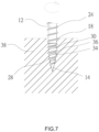
- FIG. 7 is a schematic view which illustrates the screw in FIG. 3 is being driven into a workpiece.
- FIG. 8 is a schematic view of a screw in accordance with a second embodiment of the present invention.
- FIG. 9 is a schematic view of a screw in accordance with a third embodiment of the present invention.
- FIG. 10 is a schematic view which illustrates the screw in FIG. 9 has been driven into a building structure.
- FIGS. 3 through 6 of the drawings A screw according to a first embodiment of the present invention is shown in FIGS. 3 through 6 of the drawings and generally designated 10 .
- the screw 10 includes a shank 12 , a screw-in portion 14 , a head portion 16 , and a thread 18 .
- the shank 12 has substantially the same shank diameter and defines a longitudinal axis X.
- the shank 12 includes front and rear segments 20 and 22 spaced from each other along the longitudinal axis X.
- the screw-in portion 14 integrally links the front segment 20 of the shank 12 , and the head portion 16 forms at the rear segment 22 of the shank 12 .
- the screw-in portion 14 has a tapered section with a tip 23 and has a length L 1 in the direction of the longitudinal axis X.
- the thread 18 is helically formed around both the screw-in portion 14 and the shank 12 and extends to the middle segment or the rear segment 22 of the shank 12 from the screw-in portion 14 .
- the thread 18 includes a plurality of thread convolutions 24 , and each thread convolution 24 has a thread height H 1 (that is, the distance between the crest and the root of the thread 18 , normal to the longitudinal axis X).
- a pitch P is defined between two adjacent thread convolutions 24 , and the screw-in portion length L 1 is generally greater than the pitch P
- Each thread convolution 24 has an upper tooth surface 26 facing the head portion 16 and a lower tooth surface 28 facing the screw-in portion 14 .
- the screw 10 of the present invention is characterized in that the screw-in portion 14 and/or the shank 12 is provided with at least one tapered (conical) pressing structure 30 to define at least one section having an outer diameter tapering in the direction from the head portion 16 to the screw-in portion 14 gradually (that is, expanding from the screw-in portion 14 to the head portion 16 gradually).
- at least one tapered (conical) pressing structure 30 to define at least one section having an outer diameter tapering in the direction from the head portion 16 to the screw-in portion 14 gradually (that is, expanding from the screw-in portion 14 to the head portion 16 gradually).
- each tapered pressing structure 30 extends from the bottom edge of the lower tooth surface 28 of one of the thread convolutions 24 towards both sides along the longitudinal axis X such that the lower tooth surface 28 of the thread convolution 24 has a lower tooth surface height (radial concave depth) H 2 that is the distance between the crest of the thread convolution 24 and the lower tooth surface 28 of the thread convolution 24 , normal to the longitudinal axis X.
- the lower tooth surface height H 2 is greater than the thread height H 1 of the thread convolution 24 around which no tapered pressing structure 30 is designed.
- three tapered pressing structures 30 are provided on the outer periphery of both the screw-in portion 14 and the front segment 20 of the shank 12 .
- Each tapered pressing structure 30 has an axial extension length L 2 in the direction of the longitudinal axis X, and the axial extension length L 2 is preferably 20-150% of the pitch P, which can maintain the best thread traction and improve the overall anti-pullout strength of the screw 10 .
- each tapered pressing structure 30 features the outer diameter thereof that gradually decreases towards the screw-in portion 14 and gradually expands towards the head portion 16 .
- each tapered pressing structure 30 includes a minor longitudinal segment 32 extending toward the screw-in portion 14 from the bottom edge of the lower tooth surface 28 of a corresponding thread convolution 24 and a major longitudinal segment 34 extending towards the head portion 16 from the bottom edge of the upper tooth surface 26 of the corresponding thread convolution 24 .
- the minor longitudinal segment 32 of one tapered pressing structure 30 and the major longitudinal segment 34 of another tapered pressing structure 30 connected to a lower end of the minor longitudinal segment 32 are provided between two adjacent thread convolutions 24 .
- the annular anti-pullout plane 36 is formed by the interface between the upper end of the major longitudinal segment 34 and the lower end of the minor longitudinal segment 32 . Furthermore, a tilt angle (that is, half taper angle) ⁇ relative to the longitudinal axis X is defined along the outer periphery of the tapered pressing structures 30 and has direct effects on the radial concave depth of the lower tooth surface 28 and the expansion degree of the anti-pullout plane 36 , both of which further influence traction force and anti-pullout strength of the thread convolutions 24 . In this embodiment, the tilt angle ⁇ of the tapered pressing structures 30 relative to the longitudinal axis X is approximately equal to a tilt angle of the screw-in portion 14 relative to the longitudinal axis X.
- the tapered pressing structures 30 provided on both the screw-in portion 14 and the shank 12 may have the same or different tilt angles ⁇ with respect to the longitudinal axis X, and the best mechanical performance can be achieved when the tilt angles ⁇ is in the range of 10-30 degrees.
- the screw 10 of the present invention is screwed into a workpiece 38 such as a wood plank by the screw-in portion 14 ( FIG. 7 ),
- the workpiece 38 contacting the thread 18 is cut by the lower tooth surfaces 28 of the thread convolutions 24 in the course of the screw-in portion 14 of the screw 10 driven into the workpiece 38 .
- the thread convolutions 24 on the screw-in portion 14 and/or the front segment 20 of the shank 12 having a larger lower tooth surface height H 2
- the thread convolutions 24 exert strong traction force to pull the linked shank 12 into the workpiece 38 effectively.
- annular anti-pullout plane 36 additionally formed on each tapered pressing structure 30 and between two adjacent thread convolutions 24 on the shank 12 escalates the anti-pullout strength of the screw (as shown in the arrow in FIG. 7 ) when the screw 10 is driven into the workpiece 38 .
- the minor longitudinal segments 32 of the tapered pressing structures 30 helically extend on the lower tooth surfaces 28 of consecutive thread convolutions 24 on the screw-in portion 14 and the shank 12 along the longitudinal axis X. Accordingly, in the process of screwing the screw 10 into the workpiece 38 , the outer diameter of the tapered pressing structure 30 gradually converges towards the screw-in portion 14 , which can exert less radial tension on the workpiece 38 during the screwing process to further reduce the driving resistance and prevent the workpiece from cracking due to extrusion.
- the plurality of tapered pressing structures 30 may have the same or different axial extension lengths L 2 .
- the tapered pressing structures 30 on both the screw-in portion 14 and the shank 12 are not limited to consecutive tapered pressing structures, for example, may be composed of several discontinuous tapered pressing structures.
- FIG. 8 illustrates a screw 10 in a second embodiment of the present invention.
- the bottom edge of the lower tooth surface 28 of each thread convolution 24 on the shank 12 is provided with a tapered pressing structure 30 to define a plurality of sections whose outer diameters taper in the direction from the head portion 16 towards the screw-in portion 14 gradually (expand from the screw-in portion 14 toward the head portion 16 gradually).
- a major longitudinal segment 34 is provided between any two adjacent thread convolutions 24 , so that the number of the anti-pullout planes 36 formed on the shank 12 increase.
- FIG. 9 illustrates a screw 10 in a third embodiment of the present invention.
- the screw 10 further includes a plurality of slantwise ribs 40 designed on the outer periphery of the shank 12 and between two adjacent thread convolutions 24 for better removal of debris, so that the shank 12 can be easily screwed into the workpiece, and the arrangement of the tapered pressing structures 30 can improve the overall anchoring force.
- FIG. 10 illustrates that after the screw 10 of the present invention is locked into a building structure 42 , except for the resultant force based on component forces generated in the direction of the external force by the upper tooth surfaces 26 of the thread convolutions 24 on the side of the head portion 16 to resist the pullout force, utilizing the lower tooth surface height of the screw 24 on the side of the screw-in portion 14 to be deeper than the screw height of the shank 12 and utilizing the anti-pullout planes 36 formed on the shank 12 , the overall anti-pullout strength of the screw 10 is effectively improved.
- the screw 10 includes a single thread 18 .
- the screw 10 of the present invention may include multiple threads, for example, two threads with high thread convolutions and low thread convolutions, respectively.
- the tapered pressing structures 30 can be designed on the lower tooth surface of thread convolutions of a single thread or on the lower tooth surfaces of thread convolutions 24 of the multiple threads to increase the traction force of the thread convolutions biting into the workpiece and increase the anti-pullout strength of the screw 10 .
Landscapes
- Engineering & Computer Science (AREA)
- General Engineering & Computer Science (AREA)
- Mechanical Engineering (AREA)
- Physics & Mathematics (AREA)
- Geometry (AREA)
- Wood Science & Technology (AREA)
- Chemical & Material Sciences (AREA)
- Dispersion Chemistry (AREA)
- Life Sciences & Earth Sciences (AREA)
- Connection Of Plates (AREA)
- Dowels (AREA)
- Materials For Medical Uses (AREA)
- Stringed Musical Instruments (AREA)
- Saccharide Compounds (AREA)
- Mutual Connection Of Rods And Tubes (AREA)
- Joining Of Building Structures In Genera (AREA)
Abstract
Description
Claims (6)
Applications Claiming Priority (2)
| Application Number | Priority Date | Filing Date | Title |
|---|---|---|---|
| TW109133451A TWI809316B (en) | 2020-09-26 | 2020-09-26 | Anti-pullout low-resistance screw |
| TW109133451 | 2020-09-26 |
Publications (2)
| Publication Number | Publication Date |
|---|---|
| US20220099130A1 US20220099130A1 (en) | 2022-03-31 |
| US11788569B2 true US11788569B2 (en) | 2023-10-17 |
Family
ID=80442262
Family Applications (1)
| Application Number | Title | Priority Date | Filing Date |
|---|---|---|---|
| US17/109,272 Active 2041-06-19 US11788569B2 (en) | 2020-09-26 | 2020-12-02 | Anti-pullout and low-resistance screw |
Country Status (4)
| Country | Link |
|---|---|
| US (1) | US11788569B2 (en) |
| EP (1) | EP3974665B1 (en) |
| CN (1) | CN114278657B (en) |
| TW (1) | TWI809316B (en) |
Citations (15)
| Publication number | Priority date | Publication date | Assignee | Title |
|---|---|---|---|---|
| US4652194A (en) * | 1984-11-26 | 1987-03-24 | Fujibyora Co., Ltd. | Anchor bolt |
| US5294227A (en) * | 1991-11-23 | 1994-03-15 | Hilti Aktiengesellschaft | Self-tapping screw |
| US5569009A (en) * | 1992-11-26 | 1996-10-29 | Kabushiki Kaisha Suzuki Rashi Seisakusho | Loosening prevention screw |
| US5957646A (en) * | 1998-11-02 | 1999-09-28 | Anthony C. Giannuzzi | Enhanced strength screw-type masonry anchor |
| US20070297871A1 (en) * | 2006-06-26 | 2007-12-27 | Ying-Kung Lu | Power tap structure |
| US7704030B2 (en) * | 2007-10-25 | 2010-04-27 | Zyh Yin Enterprise Co., Ltd. | Screw for use in nonmetal objects |
| US20100196121A1 (en) * | 2007-06-20 | 2010-08-05 | Unisteel Technology International Limited | Thread forming screw thread and corresponding thread roll die |
| US7862279B2 (en) * | 2006-11-22 | 2011-01-04 | Swg Schraubenwerk Gaisbach Gmbh | Screw |
| US20120034048A1 (en) * | 2009-02-16 | 2012-02-09 | Unisteel Technology Limited | Self-tapping thread forming screw and corresponding thread roll die |
| US8182186B2 (en) * | 2007-10-31 | 2012-05-22 | Hilti Aktiengesellschaft | Screw |
| US8382811B2 (en) * | 2009-06-19 | 2013-02-26 | U.S. Spine, Inc. | Triple lead bone screw |
| US20140023457A1 (en) * | 2012-07-20 | 2014-01-23 | Black & Decker Inc. | Masonry screws |
| US20180106287A1 (en) | 2015-05-12 | 2018-04-19 | Adolf Würth Gmbh & Co.Kg | Screw Having Discontinuous Scraping Edges |
| US10480560B2 (en) | 2013-07-08 | 2019-11-19 | Adolf Würth GmbH & Co. KG | Wood screw with intermediate thread sections tapering to the front |
| US10859107B2 (en) * | 2017-04-18 | 2020-12-08 | Würth International Ag | Wood screw having a crescent-shaped protrusion between thread turns |
Family Cites Families (13)
| Publication number | Priority date | Publication date | Assignee | Title |
|---|---|---|---|---|
| US1336773A (en) * | 1916-12-14 | 1920-04-13 | Caldweil John William | Screw |
| US5570983A (en) * | 1994-09-27 | 1996-11-05 | Hollander; Andrew A. | Reduced-friction screw |
| JPH1162933A (en) * | 1997-08-22 | 1999-03-05 | Nitto Seiko Co Ltd | screw |
| JP4531510B2 (en) * | 2004-09-28 | 2010-08-25 | 誠一朗 高崎 | Wood screw |
| TWM294585U (en) * | 2006-01-09 | 2006-07-21 | Easylink Ind Co Ltd | Screw structure |
| CN203906501U (en) * | 2014-06-05 | 2014-10-29 | 宽仕工业股份有限公司 | cement screw |
| DE102015100037A1 (en) * | 2015-01-05 | 2016-07-07 | Adolf Würth GmbH & Co. KG | Screw with discontinuity at intermediate threaded portion |
| CN105545922A (en) * | 2016-01-26 | 2016-05-04 | 深圳市中金科五金制造有限公司 | Complete-thread guide screw good in locking performance |
| CN107420403B (en) * | 2016-05-23 | 2019-08-27 | 徐国泰 | Screw with a thread |
| TWI614417B (en) * | 2017-03-20 | 2018-02-11 | 甫商有限公司 | Screw with cutting teeth |
| TWI622710B (en) * | 2017-05-02 | 2018-05-01 | 徐敏豪 | Screw for a thin iron plate |
| CN107654465A (en) * | 2017-10-26 | 2018-02-02 | 启东天山工具有限公司 | A kind of novel spiral adjusting screw |
| TWI683966B (en) * | 2018-09-26 | 2020-02-01 | 金美多實業有限公司 | Screw |
-
2020
- 2020-09-26 TW TW109133451A patent/TWI809316B/en active
- 2020-11-24 CN CN202011330931.XA patent/CN114278657B/en active Active
- 2020-12-02 US US17/109,272 patent/US11788569B2/en active Active
- 2020-12-03 EP EP20211418.7A patent/EP3974665B1/en active Active
Patent Citations (15)
| Publication number | Priority date | Publication date | Assignee | Title |
|---|---|---|---|---|
| US4652194A (en) * | 1984-11-26 | 1987-03-24 | Fujibyora Co., Ltd. | Anchor bolt |
| US5294227A (en) * | 1991-11-23 | 1994-03-15 | Hilti Aktiengesellschaft | Self-tapping screw |
| US5569009A (en) * | 1992-11-26 | 1996-10-29 | Kabushiki Kaisha Suzuki Rashi Seisakusho | Loosening prevention screw |
| US5957646A (en) * | 1998-11-02 | 1999-09-28 | Anthony C. Giannuzzi | Enhanced strength screw-type masonry anchor |
| US20070297871A1 (en) * | 2006-06-26 | 2007-12-27 | Ying-Kung Lu | Power tap structure |
| US7862279B2 (en) * | 2006-11-22 | 2011-01-04 | Swg Schraubenwerk Gaisbach Gmbh | Screw |
| US20100196121A1 (en) * | 2007-06-20 | 2010-08-05 | Unisteel Technology International Limited | Thread forming screw thread and corresponding thread roll die |
| US7704030B2 (en) * | 2007-10-25 | 2010-04-27 | Zyh Yin Enterprise Co., Ltd. | Screw for use in nonmetal objects |
| US8182186B2 (en) * | 2007-10-31 | 2012-05-22 | Hilti Aktiengesellschaft | Screw |
| US20120034048A1 (en) * | 2009-02-16 | 2012-02-09 | Unisteel Technology Limited | Self-tapping thread forming screw and corresponding thread roll die |
| US8382811B2 (en) * | 2009-06-19 | 2013-02-26 | U.S. Spine, Inc. | Triple lead bone screw |
| US20140023457A1 (en) * | 2012-07-20 | 2014-01-23 | Black & Decker Inc. | Masonry screws |
| US10480560B2 (en) | 2013-07-08 | 2019-11-19 | Adolf Würth GmbH & Co. KG | Wood screw with intermediate thread sections tapering to the front |
| US20180106287A1 (en) | 2015-05-12 | 2018-04-19 | Adolf Würth Gmbh & Co.Kg | Screw Having Discontinuous Scraping Edges |
| US10859107B2 (en) * | 2017-04-18 | 2020-12-08 | Würth International Ag | Wood screw having a crescent-shaped protrusion between thread turns |
Also Published As
| Publication number | Publication date |
|---|---|
| US20220099130A1 (en) | 2022-03-31 |
| CN114278657A (en) | 2022-04-05 |
| EP3974665B1 (en) | 2023-09-13 |
| CN114278657B (en) | 2024-02-20 |
| TW202212706A (en) | 2022-04-01 |
| EP3974665A1 (en) | 2022-03-30 |
| TWI809316B (en) | 2023-07-21 |
| EP3974665C0 (en) | 2023-09-13 |
Similar Documents
| Publication | Publication Date | Title |
|---|---|---|
| KR102238236B1 (en) | Screw | |
| US6296433B1 (en) | Large diameter tapcon with debris reservoir end or tip | |
| US20170016468A1 (en) | Screw | |
| CN1253243A (en) | Enhanced strength screw-type masonry anchor | |
| US20230392636A1 (en) | Concrete fastener | |
| JP2005114085A (en) | Tapping screw | |
| TWI622710B (en) | Screw for a thin iron plate | |
| CN1764790A (en) | Tapping screw for low ductility material | |
| JP7106606B2 (en) | wood screw structure | |
| US8784017B2 (en) | Drill bit | |
| US11788569B2 (en) | Anti-pullout and low-resistance screw | |
| EP3121462B1 (en) | Screw | |
| EP3855026A1 (en) | Screw | |
| US6176664B1 (en) | Fastening screw and method of forming same | |
| JP2018017283A (en) | Building structure screws | |
| CN107420403B (en) | Screw with a thread | |
| US20210222723A1 (en) | Screw | |
| TWI683966B (en) | Screw | |
| US20230392637A1 (en) | Concrete fastener | |
| US20230160413A1 (en) | Threaded Fastener With Scalloped Minor Diameter | |
| JP7357967B2 (en) | Tap | |
| JP7016852B2 (en) | Wood screw structure | |
| CN112762077A (en) | Shear bolt | |
| US4269902A (en) | Extruding and tapping screw and blank for manufacture of such screw | |
| JPH0366910A (en) | Thread forming screw |
Legal Events
| Date | Code | Title | Description |
|---|---|---|---|
| FEPP | Fee payment procedure |
Free format text: ENTITY STATUS SET TO UNDISCOUNTED (ORIGINAL EVENT CODE: BIG.); ENTITY STATUS OF PATENT OWNER: SMALL ENTITY |
|
| FEPP | Fee payment procedure |
Free format text: ENTITY STATUS SET TO SMALL (ORIGINAL EVENT CODE: SMAL); ENTITY STATUS OF PATENT OWNER: SMALL ENTITY |
|
| STPP | Information on status: patent application and granting procedure in general |
Free format text: DOCKETED NEW CASE - READY FOR EXAMINATION |
|
| STPP | Information on status: patent application and granting procedure in general |
Free format text: NON FINAL ACTION MAILED |
|
| STPP | Information on status: patent application and granting procedure in general |
Free format text: RESPONSE TO NON-FINAL OFFICE ACTION ENTERED AND FORWARDED TO EXAMINER |
|
| STPP | Information on status: patent application and granting procedure in general |
Free format text: NON FINAL ACTION MAILED |
|
| STPP | Information on status: patent application and granting procedure in general |
Free format text: NOTICE OF ALLOWANCE MAILED -- APPLICATION RECEIVED IN OFFICE OF PUBLICATIONS |
|
| STPP | Information on status: patent application and granting procedure in general |
Free format text: PUBLICATIONS -- ISSUE FEE PAYMENT RECEIVED |
|
| STPP | Information on status: patent application and granting procedure in general |
Free format text: PUBLICATIONS -- ISSUE FEE PAYMENT VERIFIED |
|
| STCF | Information on status: patent grant |
Free format text: PATENTED CASE |