US11786279B2 - Modular spinal fixation device - Google Patents
Modular spinal fixation device Download PDFInfo
- Publication number
- US11786279B2 US11786279B2 US17/393,832 US202117393832A US11786279B2 US 11786279 B2 US11786279 B2 US 11786279B2 US 202117393832 A US202117393832 A US 202117393832A US 11786279 B2 US11786279 B2 US 11786279B2
- Authority
- US
- United States
- Prior art keywords
- insert
- housing
- bone screw
- retaining ring
- proximal
- Prior art date
- Legal status (The legal status is an assumption and is not a legal conclusion. Google has not performed a legal analysis and makes no representation as to the accuracy of the status listed.)
- Active
Links
Images


Classifications
-
- A—HUMAN NECESSITIES
- A61—MEDICAL OR VETERINARY SCIENCE; HYGIENE
- A61B—DIAGNOSIS; SURGERY; IDENTIFICATION
- A61B17/00—Surgical instruments, devices or methods
- A61B17/56—Surgical instruments or methods for treatment of bones or joints; Devices specially adapted therefor
- A61B17/58—Surgical instruments or methods for treatment of bones or joints; Devices specially adapted therefor for osteosynthesis, e.g. bone plates, screws or setting implements
- A61B17/68—Internal fixation devices, including fasteners and spinal fixators, even if a part thereof projects from the skin
- A61B17/72—Intramedullary devices, e.g. pins or nails
- A61B17/7233—Intramedullary devices, e.g. pins or nails with special means of locking the nail to the bone
- A61B17/7241—Intramedullary devices, e.g. pins or nails with special means of locking the nail to the bone the nail having separate elements through which screws pass
-
- A—HUMAN NECESSITIES
- A61—MEDICAL OR VETERINARY SCIENCE; HYGIENE
- A61B—DIAGNOSIS; SURGERY; IDENTIFICATION
- A61B17/00—Surgical instruments, devices or methods
- A61B17/56—Surgical instruments or methods for treatment of bones or joints; Devices specially adapted therefor
- A61B17/58—Surgical instruments or methods for treatment of bones or joints; Devices specially adapted therefor for osteosynthesis, e.g. bone plates, screws or setting implements
- A61B17/68—Internal fixation devices, including fasteners and spinal fixators, even if a part thereof projects from the skin
- A61B17/70—Spinal positioners or stabilisers, e.g. stabilisers comprising fluid filler in an implant
- A61B17/7001—Screws or hooks combined with longitudinal elements which do not contact vertebrae
- A61B17/7035—Screws or hooks, wherein a rod-clamping part and a bone-anchoring part can pivot relative to each other
- A61B17/7037—Screws or hooks, wherein a rod-clamping part and a bone-anchoring part can pivot relative to each other wherein pivoting is blocked when the rod is clamped
-
- A—HUMAN NECESSITIES
- A61—MEDICAL OR VETERINARY SCIENCE; HYGIENE
- A61B—DIAGNOSIS; SURGERY; IDENTIFICATION
- A61B17/00—Surgical instruments, devices or methods
- A61B17/56—Surgical instruments or methods for treatment of bones or joints; Devices specially adapted therefor
- A61B17/58—Surgical instruments or methods for treatment of bones or joints; Devices specially adapted therefor for osteosynthesis, e.g. bone plates, screws or setting implements
- A61B17/68—Internal fixation devices, including fasteners and spinal fixators, even if a part thereof projects from the skin
- A61B17/70—Spinal positioners or stabilisers, e.g. stabilisers comprising fluid filler in an implant
- A61B17/7074—Tools specially adapted for spinal fixation operations other than for bone removal or filler handling
- A61B17/7091—Tools specially adapted for spinal fixation operations other than for bone removal or filler handling for applying, tightening or removing longitudinal element-to-bone anchor locking elements, e.g. caps, set screws, nuts or wedges
-
- A—HUMAN NECESSITIES
- A61—MEDICAL OR VETERINARY SCIENCE; HYGIENE
- A61B—DIAGNOSIS; SURGERY; IDENTIFICATION
- A61B17/00—Surgical instruments, devices or methods
- A61B17/56—Surgical instruments or methods for treatment of bones or joints; Devices specially adapted therefor
- A61B17/58—Surgical instruments or methods for treatment of bones or joints; Devices specially adapted therefor for osteosynthesis, e.g. bone plates, screws or setting implements
- A61B17/68—Internal fixation devices, including fasteners and spinal fixators, even if a part thereof projects from the skin
- A61B17/70—Spinal positioners or stabilisers, e.g. stabilisers comprising fluid filler in an implant
- A61B17/7074—Tools specially adapted for spinal fixation operations other than for bone removal or filler handling
- A61B17/7076—Tools specially adapted for spinal fixation operations other than for bone removal or filler handling for driving, positioning or assembling spinal clamps or bone anchors specially adapted for spinal fixation
- A61B17/7082—Tools specially adapted for spinal fixation operations other than for bone removal or filler handling for driving, positioning or assembling spinal clamps or bone anchors specially adapted for spinal fixation for driving, i.e. rotating, screws or screw parts specially adapted for spinal fixation, e.g. for driving polyaxial or tulip-headed screws
Definitions
- the present disclosure relates to spinal fixation devices. More particularly, the present disclosure relates to head assemblies for use in modular spinal fixation devices that are connectable to spinal rods used in spinal constructs.
- spinal fixation devices e.g., alignment systems
- One type of spinal construct may include, for example, one or more spinal rods that can be placed parallel to the spine with fixation devices (such as hooks, screws, or plates) interconnected between the spinal rods and selected portions of the spine.
- fixation devices such as hooks, screws, or plates
- the spinal rods can be connected to each other via cross-connecting members to provide a more rigid support and alignment system.
- the use of these devices may be permanently implanted in the patient.
- the devices may be implanted only as a temporary means of stabilizing or fixing the bones or bone fragments, with subsequent removal when no longer needed.
- the surgeon directs the screw into the vertebral body before attaching any additional mechanical hardware, such as rods or bands.
- the surgeon typically attaches the spinal fixation devices to the spine in appropriate anatomical positions and then attaches the spinal rod to the fixation devices.
- the surgeon manipulates the spinal column and/or individual vertebra to provide the desired treatment for the spinal defect. Subsequently, the spinal rod and fixation devices are locked in a desired arrangement.
- spinal fixation devices are suitable for the above uses, there may exist a need for spinal fixation devices that can reduce the time and labor required by a user to insert a fixation device, such as a screw, into a vertebra.
- a spinal fixation device in accordance with the present disclosure and includes modular head assembly and a bone screw.
- the modular head assembly includes a housing, an anvil, an insert, and a snap ring.
- the housing defines a proximal surface and an opposite, distal surface, the proximal and distal surfaces defining a throughbore therethrough.
- the anvil is configured to be slidably received within a portion of the throughbore.
- the insert defines a proximal surface and an opposite, distal surface.
- the distal surface defines a first counterbore therein terminating at a first annular surface.
- the first annular surface defines a second counterbore therein terminating at a second annular surface.
- the snap ring is configured to be disposed within the first counterbore of the insert when in a first configuration, and within the second counterbore of the insert when in a second configuration.
- the bone screw defines a head at a proximal portion thereof and a shank extending distally from the head. The bone screw is configured to be received within a portion of the snap ring.
- the distal surface of the housing may define a third counterbore therein terminating at an annular face.
- the annular face of the third counterbore may define a slot extending in a proximal direction.
- the slot extending through an inner surface of the throughbore.
- the anvil may define a proximal surface and an opposite, distal surface, defining an outer surface extending therebetween.
- the outer surface defines a tab extending between the proximal and distal surfaces, the tab configured to be slidably received within the slot.
- an inner surface of the third counterbore may define threads thereon.
- the insert may define an outer surface extending between the proximal and distal surfaces, the outer surface defining threads thereon configured to threadably engage the threads of the third counterbore.
- the snap ring may define a proximal surface and an opposite, distal surface, the proximal and distal surfaces defining a lumen therethrough.
- the proximal and distal surfaces of the snap ring may define an outer surface extending therebetween, the outer surface defining a slot extending through the proximal and distal surfaces and being in open communication with the lumen.
- the lumen of the snap ring may define a longitudinal axis extending along a centerline thereof, the lumen defining an inner surface having a concave profile extending along the longitudinal axis.
- the snap ring may be formed from a resilient material.
- an intersection of the outer surface of the snap ring and the distal surface of the snap ring may define an undercut configured to abut a portion of the second counterbore of the insert.
- a method of assembling a spinal fixation device includes assembling a modular head assembly, including advancing an anvil within a throughbore defined through a proximal and distal surface of a housing, advancing a snap ring within a first counterbore defined through a proximal surface on an insert, and rotating the insert in a first direction to threadably engage a first plurality of threads defined on an outer surface of the insert with a second plurality of threads defined on an inner surface of a second counterbore defined through the distal surface of the housing until the insert is threadably coupled to the housing.
- the method further includes placing a bore defined through a distal surface of the insert adjacent a head of a bone screw and advancing the modular head assembly toward the head of the bone screw such that the head of the bone screw is received within the bore of the insert, and thereafter, within a lumen defined through distal and proximal surfaces of the snap ring to retain the head of the bone screw therein.
- advancing the anvil within the throughbore of the housing may include advancing a tab defined on an outer surface of the anvil within a slot defined within an inner surface of the throughbore to inhibit rotation of the anvil relative to the housing.
- advancing the head of the bone screw within the lumen of the snap ring may include advancing the head of the bone screw within the lumen of the snap ring such that a concave profile defined on an inner surface of the lumen engages the head of the bone screw to retain the head of the bone screw within the lumen.
- advancing the head of the bone screw within the lumen of the snap ring may include the snap ring defining a slot extending through an outer surface thereof and extending through the proximal and distal surfaces, the slot enabling the snap ring to expand to a second, expanded state, as the head of the bone screw is received within the lumen, and return to a first, unexpanded state once the head of the bone screw is fully received within the lumen.
- the method may include advancing a spinal rod within a slot defined through an outer surface of the housing and extending through the proximal surface thereof.
- the method may include rotating a set screw in a first direction to threadably engage threads defined on an outer surface of the set screw with threads defined on an inner surface of the throughbore of the housing, wherein rotation of the set screw in the first direction causes the set screw to translate in a distal direction which causes a corresponding distal translation of the spinal rid, the anvil, and the snap ring.
- the method may include further rotating the set screw in the first direction to cause the snap ring to further translate in a distal direction and be received within a second counterbore defined through a first annular surface defined by the first counterbore of the insert, wherein reception of the snap ring within the second counterbore causes the snap ring to compress around the head of the bone screw and lock the orientation of the bone screw relative to the modular head assembly.
- a method of assembling a spinal fixation device includes advancing a bone screw within an incision formed in a patient's body, driving the bone screw into a vertebra, the bone screw including a head at a proximal portion thereof and a threaded shank extending distally from the head.
- the method further includes assembling a modular head assembly, including advancing an anvil within a throughbore defined through a proximal and distal surface of a housing, advancing a snap ring within a first counterbore defined through a proximal surface of an insert, and rotating the insert in a first direction to threadably engage a first plurality of threads defined on an outer surface of the insert with a second plurality of threads defined on an inner surface of a second counterbore defined through the distal surface of the housing until the insert is threadably coupled to the housing.
- the method further includes placing a bore defined through a distal surface of the insert adjacent the head of the bone screw and advancing the modular head assembly toward the head of the bone screw such that the head of the bone screw is received within the bore of the insert, and thereafter, within a lumen defined through distal and proximal surfaces of the snap ring to retain the head of the bone screw therein.
- FIG. 1 A is a front view of a spinal fixation device including a modular head assembly and a bone screw in accordance with an embodiment of the present disclosure
- FIG. 1 B is a cross-sectional view of the spinal fixation device of FIG. 1 A , taken along section-line 1 B- 1 B of FIG. 1 A ;
- FIG. 2 is a perspective view of the spinal fixation device of FIG. 1 A , shown with parts separated;
- FIG. 3 A is a perspective view of a housing of the modular head assembly of FIG. 1 A ;
- FIG. 3 B is a cross-sectional view of the housing of FIG. 3 A , taken along section-line 3 B- 3 B of FIG. 3 A ;
- FIG. 4 is a perspective view of an anvil of the modular head assembly of FIG. 1 A ;
- FIG. 5 is a perspective view of a snap-ring of the modular head assembly of FIG. 1 A ;
- FIG. 6 A is a perspective view of an insert of the modular head assembly of FIG. 1 A ;
- FIG. 6 B is a cross-sectional view of the insert of FIG. 6 A , taken along section-line 6 B- 6 B of FIG. 6 A ;
- FIG. 7 A is a front view of the spinal fixation device of FIG. 1 A , shown in an assembled state;
- FIG. 7 B is a cross-sectional view of the spinal fixation device of FIG. 1 A , taken along section-line 7 B- 7 B of FIG. 7 A ;
- FIG. 8 A is a front view of the spinal fixation device of FIG. 1 A , shown with a spinal rod and set screw in accordance with the present disclosure;
- FIG. 8 B is a section view of the spinal fixation device of FIG. 1 A and the spinal rod and set screw of FIG. 8 A , taken along section-line 8 B- 8 B of FIG. 8 A ;
- FIG. 9 A is a front view of another embodiment of a spinal fixation device including a modular head assembly and bone screw provided in accordance with the present disclosure
- FIG. 9 B is a cross-sectional view of the spinal fixation device of FIG. 9 A , taken along section-line 9 B- 9 B of FIG. 9 A ;
- FIG. 10 is a perspective view of the spinal fixation device of FIG. 9 A , shown with parts separated;
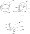
- FIG. 11 is a perspective view of a snap ring of the modular head assembly of FIG. 9 A ;
- FIG. 12 is a perspective view of an anvil of the modular head assembly of FIG. 9 A ;
- FIG. 13 is a front view of the anvil of FIG. 12 ;
- FIG. 14 A is a front view of the spinal fixation device of FIG. 9 A , shown in an assembled state;
- FIG. 14 B is a cross-sectional view of the spinal fixation device of FIG. 9 A , taken along section-line 14 B- 14 B of FIG. 14 A ;
- FIG. 15 A is a side view of the spinal fixation device of FIG. 9 A , shown with a spinal rod and set screw provided in accordance with the present disclosure;
- FIG. 15 B is a cross-sectional view of the spinal fixation device of FIG. 9 A and the spinal rod and set screw of FIG. 15 A , taken along section-line 15 B- 15 B of FIG. 15 A ;
- FIG. 16 A is a front view of yet another embodiment of a spinal fixation device including a modular head assembly and a bone screw provided in accordance with the present disclosure
- FIG. 16 B is a cross-sectional view of the spinal fixation device of FIG. 16 A , taken along section-line 16 B- 16 B of FIG. 16 A ;
- FIG. 17 is a perspective view of the spinal fixation device of FIG. 16 A , shown with parts separated;
- FIG. 18 A is a side view of an insertion tool
- FIG. 18 B is a detail view of the area of detail indicated in FIG. 18 A .
- FIGS. 1 A, 1 B, and 2 illustrate an embodiment of a spinal fixation device provided in accordance with the present disclosure and generally identified as reference numeral 10 .
- the spinal fixation device 10 includes a modular head assembly 12 and a bone screw 14 , although it is contemplated that the spinal fixation device may only include the modular head assembly 12 , depending upon the needs of the procedure being performed. As can be appreciated, it is contemplated that the modular head assembly 12 may be utilized with a spinal hook or other similar spinal fixation devices.
- the modular head assembly 12 includes a housing 16 , an anvil 18 , a snap ring 20 , and an insert 22 .
- the housing 16 includes a body portion 16 a extending between a proximal surface 16 b and an opposite, distal surface 16 c defining a longitudinal axis A-A therethrough.
- the body portion 16 a may include any suitable profile capable of being used during spinal surgery.
- the proximal surface 16 b of the housing 16 defines a through-hole 24 therethrough that extends through the distal surface 16 c of the housing 16 .
- An inner surface 24 a of a proximal portion of the through-hole 24 defines a plurality of threads 24 b configured to threadably engage a set screw 40 ( FIG. 8 B ), as will be described in further detail hereinbelow.
- a distal portion of the inner surface 24 a of the through-hole 24 defines a pair of slots 24 c disposed in juxtaposed relation to one another and extending along the longitudinal axis A-A. Although illustrated as defining a pair of slots 24 c , it is contemplated that the inner surface 24 a of the through-hole 24 may define only one slot 24 c .
- Each slot 24 c is configured to slidably engage a corresponding feature of the anvil 18 to enable translation of the anvil 18 within the through-hole 24 , but inhibit rotation of the anvil 18 within the through-hole 24 .
- the pair of slots 24 c ensures that a U-shaped slot 28 of the housing 16 remains aligned with a concave relief 18 g ( FIG. 4 ) defined in the anvil 18 , as will be described in further detail hereinbelow.
- the distal surface 16 c of the body portion 16 a defines a counterbore 26 extending towards the proximal surface 16 b and terminating at an annular face 26 a located at a middle portion of the body portion 16 a , although it is contemplated that the counterbore 26 may extend any suitable distance from the lower portion 16 c .
- An inner surface 26 b of the counterbore 26 defines a plurality of threads 26 c configured to threadably engage the insert 22 , as will be described in further detail hereinbelow.
- An outer surface 16 d of the body portion 16 a of the housing 16 defines a U-shaped slot 28 therethrough and extending through the proximal surface 16 b thereof.
- the U-shaped slot 28 is configured to receive a spinal rod 34 ( FIG. 8 A ), as will be described in further detail hereinbelow.
- the outer surface 16 d of the body portion 16 a defines a pair of reliefs 30 therein which are aligned with the U-shaped slot 28 (e.g., oriented transverse to the longitudinal axis A-A).
- the pair of reliefs 30 is configured to engage a suitable tool (not shown) to enable a clinician to grasp and manipulate the modular head assembly 12 during the surgical procedure.
- the housing 16 may be formed from any biocompatible material suitable for use in surgical procedures, such as metallic materials (e.g., titanium (e.g., commercially pure titanium), titanium alloys, (e.g., Ti-6Al-4V), stainless steels, cobalt chrome alloys, etc.) or non-metallic materials (e.g., ceramics, polyetheretherketone (PEEK), etc.).
- metallic materials e.g., titanium (e.g., commercially pure titanium), titanium alloys, (e.g., Ti-6Al-4V), stainless steels, cobalt chrome alloys, etc.
- non-metallic materials e.g., ceramics, polyetheretherketone (PEEK), etc.
- the anvil 18 defines a body portion 18 a extending between a proximal surface 18 b and an opposite, distal surface 18 c defining a longitudinal axis B-B therethrough.
- the body portion 18 a includes a profile that is complimentary to the profile of the through-hole 24 of the housing 16 such that the anvil 18 is capable of being slidably received therein.
- An outer surface 18 d of the body portion 18 a defines a pair of tabs 18 e thereon extending along the longitudinal axis B-B. In embodiments, it is contemplated that the outer surface 18 d may form only a single tab 18 e thereon.
- Each tab 18 e is oriented 180 degrees apart relative to the other tab 18 e such that each tab 18 e of the pair of tabs 18 e is received within a corresponding slot 24 c of the pair of slots 24 c of the housing 16 to permit the anvil 18 to translate within the through-hole 24 along axis A-A, but inhibit rotation of the anvil 18 relative thereto.
- the proximal and distal surfaces 18 b , 18 c define a bore 18 f therethrough.
- the proximal surface 18 b defines a relief 18 g therein having a concave profile (e.g., extending toward the distal surface 18 c ) and configured to receive a portion of the spinal rod 34 ( FIG. 8 A ) therein.
- the anvil 18 may be formed from any material suitable for use in surgical procedures, such as those described hereinabove, and may be formed from the same or a different material than the housing 16 .
- the snap ring 20 is illustrated in FIG. 5 and is configured to be slidably received within a portion of the insert 22 ( FIG. 1 B ), as will be described in further detail hereinbelow.
- the snap ring 20 includes a generally cylindrical body 20 a extending between an upper surface 20 b and an opposite, lower surface 20 c defining a longitudinal axis C-C therethrough.
- the body 20 a may include any suitable profile, and may conform to the profile of the portion of the insert 22 in which the snap ring 20 is configured to be received.
- the upper and lower surfaces 20 b , 20 c define a lumen 20 d therethrough which defines a curvate inner surface 20 e thereon.
- the curvate inner surface 20 e defines a generally concave profile extending along the longitudinal axis C-C and generally corresponds to the profile of a head 14 a of the bone screw 14 ( FIG. 2 ).
- An outer surface 20 f of the body 20 a defines a slot 20 g therethrough extending through the inner surface 20 e of the lumen 20 d and through the upper and lower surfaces 20 b , 20 c such that the slot 20 g is in open communication with the lumen 20 d .
- the slot 20 g interrupts a perimeter of the snap ring 20 such that the snap ring 20 forms a generally C-shaped profile which enables the body 20 a to expand and compress (e.g., the outer diameter of the body 20 a increases or decreases) due to an external or internal force being applied thereto.
- the proximal surface 20 b defines a channel 20 g therein extending transverse to the longitudinal axis C-C and disposed opposite to the slot 20 d .
- the intersection of the distal surface 20 b and the inner surface 20 f of the body 20 a defines a bevel 20 i that extends towards the lumen 20 d .
- the snap ring 20 may be formed from any material suitable for use in surgical procedures such as those described hereinabove, and may be formed from the same or a different material than the housing 16 and the anvil 18 .
- the snap ring 20 is formed from a resilient material that enables the snap ring to expand and compress without being permanently deformed.
- the insert 22 includes a body 22 a defining a generally cylindrical profile extending between a proximal surface 22 b and an opposite, distal surface 22 c .
- An outer surface of the body 22 a defines a plurality of threads 22 d configured to threadably engage the plurality of threads 26 c of the counterbore 26 of the housing 16 such that the insert 22 may be threadably coupled to the housing 16 .
- the proximal surface 22 b defines a first counterbore 22 e therein terminating at a first annular surface or annular shoulder 22 f disposed approximately halfway between the proximal and distal surfaces 22 b , 22 c of the body 22 a .
- the first annular surface 22 f may be disposed at any suitable location depending upon the needs of the procedure being performed.
- the first annular surface 22 f defines a second counterbore 22 g therein terminating at a second annular surface or annular shoulder 22 h disposed adjacent the distal surface 22 c of the body 22 a .
- the second counterbore 22 g is concentric with the first counterbore 22 e and includes a diameter that is less than the first counterbore 22 e .
- the first counterbore 22 e is configured to slidably receive the snap ring 20 therein whereas the second counterbore 22 g is configured to compress the snap ring 20 as the snap ring 20 is received therein.
- the second counterbore 22 g compresses around a head of the bone screw 14 to secure the bone screw 14 in position relative to the housing 16 , as will be described in further detail hereinbelow.
- the second annular surface 22 h of the second counterbore 22 g defines a bore 22 i therethrough and extending through the distal surface 22 c of the body 22 a .
- the bore 22 i may be defined at any suitable location on the second annular surface 22 h .
- the bore 22 i defines a diameter capable of permitting the head of the bone screw 14 to pass therethrough, as will be described in further detail below.
- the insert 22 may be formed from any material suitable for use in surgical procedures such as those described hereinabove, and may be formed from the same or a different material than the housing 16 , anvil 18 , and/or snap ring 20 .
- the insert 22 is formed from a material that is as hard or harder than the material forming the snap ring 20 , such that neither the snap ring 20 nor the insert 22 is damaged as the snap ring 22 transitions from the first counterbore 22 e to the second counterbore 22 g of the insert 22 .
- a bone screw 14 capable of being used with the modular head assembly 12 is illustrated. Although generally illustrated as being a poly-axial pedicle screw, it is contemplated that the bone screw 14 may be any suitable bone screw capable of being used during spinal surgery (e.g. mono-axial or uni-axial).
- the bone screw 14 includes a head 14 a at a proximal end thereof and a shank 14 b extending distally therefrom.
- the shank 14 b includes a distal tip portion 14 c , an elongated body portion 14 d , and a proximal end 14 e that is coupled to the head 14 a (e.g., monolithically formed therewith).
- the distal tip portion 14 c is generally conically-shaped to facilitate insertion of the bone screw 14 into bone, and in embodiments, may be self-tapping or self-starting.
- the elongated body portion 14 d of the shank 14 b includes a substantially uniform outer diameter and includes a continuous helical thread 14 f of substantially uniform pitch formed thereon to allow for threaded insertion and retention of the bone screw 14 within the bone.
- the thread 14 f disposed about the elongated body portion 14 d of the shank 14 b may be single threaded, double threaded, etc., depending upon the needs of the procedure being performed.
- the shank 14 b may be cannulated to permit passage of a guide wire (not shown) or other instrumentation therethrough.
- the head 14 a of the bone screw 14 defines a generally spherical shape and defines a tool engaging recess 14 g at a proximal portion thereof that is configured to engage the engagement region 310 of the driver 300 ( FIGS. 18 A, 18 B ).
- the tool engaging recess 14 g may define any suitable shape capable of transmitting the rotational motion of the tool to the head 14 a of the bone screw, and in one non-limiting embodiment, may define a hexalobe configuration.
- the bone screw 14 may be formed from any material suitable for use in surgical procedures such as those described hereinabove, and may be formed from the same or a different material than the housing 16 , the anvil 18 , the snap ring 20 , and/or the insert 22 .
- the head 14 a of the bone screw 14 may be formed from a different material than the shank 14 b of the bone screw.
- a method of assembling the spinal fixation device 10 is illustrated. Initially, the anvil 18 is positioned below the counterbore 26 of the housing 16 with the pair of tabs 18 e of the anvil aligned with the pair of slots 24 c of the housing 16 . The anvil 18 is urged in a proximal direction into the counterbore 26 such that the pair of tabs 18 e is received within the pair of slots 24 c.
- FIGS. 7 A and 7 B illustrate the spinal fixation system 10 in an assembled state.
- the modular head assembly 12 of the spinal fixation system 10 is assembled by first aligning the pair of tabs 18 e of the anvil with the corresponding pair of slots 24 c of the through-hole 24 of the housing 16 . Once the pair of tabs 18 e is in alignment with the pair of slots 24 c , the anvil is advanced in a proximal direction within the through-hole 24 until an upper portion of the pair of tabs 18 e abuts a proximal-most portion of the pair of slots 24 c .
- the snap ring 20 is placed adjacent the counterbore 26 of the housing 16 and advanced in a proximal direction such that the snap ring 20 is slidably received therein.
- the insert 22 is initially placed adjacent the counterbore 26 of the housing 16 .
- the insert 22 is then rotated in a first direction such that the plurality of threads 22 d of the insert threadably engages the corresponding plurality of threads 26 c of the counterbore 26 of the housing 16 .
- the insert 22 is further rotated until the insert 22 is fully received within the counterbore 26 . In this position, the anvil 18 is in a proximal most position and the snap ring 20 is disposed within the first counterbore 22 e of the insert 22 such that the snap ring 20 is in a first, uncompressed state.
- the bone screw 14 is driven into bone using the driver 300 ( FIGS. 18 A, 18 B ) engaged with the tool engaging recess 14 g of the head 14 a of the bone screw 14 .
- the modular head assembly 12 With the bone screw 14 secured at a desired location, the modular head assembly 12 is placed adjacent the head 14 a of the bone screw 14 .
- the modular head assembly 12 is then advanced in a distal direction such that the head 14 a of the bone screw 14 is received within the bore 22 i of the insert 22 , and thereafter, within the lumen 20 d of the snap ring 20 .
- the head 14 a of the bone screw 14 advances within the bore 22 i of the snap ring 20 , the head 14 a causes the snap ring 20 to expand (e.g., the diameter enlarges) to accept the head 14 a therein.
- the concave inner surface 20 e of the lumen 20 d conforms to the spheroid profile of the head 14 a such that the diameter of the snap ring 20 reduces from an expanded state during insertion of the head 14 a therein to a compressed state where the inner diameter of the lumen 20 d conforms to the diameter of the head 14 a and provides a compressive force thereon (e.g., an intermediate position that is between the expanded state and the clamped state described hereinbelow).
- the axial orientation of the bone screw 14 relative to the modular head assembly 10 may be locked when a suitable spinal rod 34 is secured within the housing 16 using a suitable set screw 40 .
- the spinal rod 34 is inserted within the U-shaped slot 28 of the housing 16 and is received within the relief 18 g and abuts the anvil 18 .
- a suitable tool or driver 300 FIGS. 18 A and 18 B ) inserted within a tool engaging recess 40 a defined within the set screw 40 , the set screw 40 is inserted into the through-hole 24 of the housing.
- the set screw 40 defines a plurality of threads 42 thereon to threadably engage the plurality of threads 24 b of the through-hole 24 .
- the set screw 40 is rotated in a first direction to cause the set screw 40 to translate in a distal direction and urge the spinal rod 34 in a corresponding distal direction.
- the set screw 40 continues rotation of the set screw 40 in the first direction causes the set screw 40 to further urge the spinal rod 34 in a distal direction within the through-hole 24 and in turn, causes the spinal rod 34 to urge the anvil 18 in a distal direction.
- the distal translation of the anvil 18 urges the snap ring 20 , along with the bone screw 14 captured therewithin, to translate into the second counterbore 22 g of the insert 22 .
- the smaller diameter of the second counterbore 22 g causes the snap ring 20 to compress around the head 14 a of the bone screw 14 , thereby clamping the head 14 a of the bone screw 14 and fixing the rotational and angular position of the bone screw 14 with respect the housing 16 .
- the set screw 40 is rotated in a second, opposite direction to translate the set screw 40 in a proximal direction. Continued rotation of the set screw 40 in the second direction enables the set screw 40 to be removed from the through-hole 24 of the housing 16 . As can be appreciated, it may not be necessary to completely remove the set screw 40 from the housing 16 to enable repositioning of the modular head assembly 10 relative to the bone screw 14 . At this point, the housing 16 of the modular head assembly 10 may be urged in a distal direction.
- the head 14 a of the bone screw 14 urges the snap ring 20 in a proximal direction, which in turn, causes the snap ring 20 to translate from the second counterbore 22 g of the insert 22 to the first counterbore 22 e of the insert 22 .
- Translation from the second counterbore 22 g to the first counterbore 22 e enables the snap ring 20 to transition from a second, compressed state where the modular head assembly 10 is inhibited from movement relative to the bone screw 14 , to the first, uncompressed state where the modular head assembly 10 is permitted to move relative to the bone screw 14 .
- the modular head assembly 10 may be placed in the desired position relative to the bone screw 14 and modular head assembly 10 may be locked relative to the bone screw using the procedure described hereinabove.
- FIGS. 9 A, 9 B, and 10 another embodiment of a spinal fixation device is illustrated and generally identified by reference numeral 110 .
- the spinal fixation device 110 is substantially similar to the spinal fixation device 10 , and therefore, only the differences therebetween will be described hereinbelow in the interest of brevity.
- the pair of tabs 118 e of the anvil 118 extend distal of the lower surface 118 c to define a corresponding pair of extensions 118 h .
- only a single extension 118 h may be defined regardless of if there is only a single tab 118 e or a pair of tabs 118 e defined on the anvil 118 .
- An inner surface 118 i of each extension of the pair of extensions 118 h defines a barb or protrusion 118 j extending toward one another (e.g., in an interior direction) and are configured to grasp a corresponding feature defined in the head 114 a of the bone screw 114 , as will be described in further detail hereinbelow.
- the inner surface 120 e of the snap ring 120 defines a pair of opposed channels 120 g therein extending through each of the upper and lower surfaces 120 b , 120 c .
- the pair of opposed channels 120 g is configured to slidably receive the pair of extensions 118 h of the anvil 118 and inhibit rotation of the snap ring 120 relative to the anvil 118 , and in turn, the housing 116 .
- FIGS. 9 A, 9 B, and 10 another embodiment of a bone screw is provided and generally identified by reference numeral 114 .
- the bone screw 114 is substantially similar to the bone screw 14 and therefore only the differences therebetween will be described hereinbelow in the interest of brevity.
- An outer surface 114 d of the head 114 of bone screw 114 defines a pair of opposed reliefs 114 e .
- the pair of reliefs 114 e is disposed approximately at the equator (e.g., the widest portion of the head 114 ) and define a generally triangular profile such that the apex of the pair of reliefs is disposed adjacent the distal end of the head 114 a .
- Each relief of the pair of reliefs 114 e is configured to slidably receive a respective extension of the pair of extensions 118 h of the anvil 118 .
- the depth and width of the pair of reliefs 114 d may vary depending upon how much angular movement of the bone screw 114 relative to the housing 116 is desired. In this manner, a pair of reliefs 114 d having a smaller width will allow a corresponding small amount of angular movement of the bone screw 114 relative to the housing 116 of the modular head assembly 112 . Similarly, a pair of reliefs 114 e having a larger width will allow a corresponding larger amount of angular movement of the bone screw 114 relative to the housing 116 .
- the pair of reliefs 114 e inhibits rotation of the bone screw 114 about the longitudinal axis C-C since after assembly, the pair of extensions 118 h compress against the pair of reliefs 114 e to constrain movement of the bone screw 114 to a single plane.
- Assembly of the spinal fixation device 110 is substantially similar to the assembly of the spinal fixation device 10 , and therefore only the differences therebetween will be described in detail hereinbelow.
- the pair of opposed channels 120 g of the snap ring is aligned with the pair of extensions 118 h of the anvil 118 such that as the snap ring 120 is urged in a proximal direction, the pair of extensions 118 h of the anvil 118 are received within the pair of opposed channels 120 g .
- the pair of reliefs 114 e of the bone screw 114 is initially aligned with the pair of extensions 118 h of the anvil 118 . Thereafter, the bone screw 114 is urged in a proximal direction such that each extension of the pair of extensions 118 h is received within a corresponding relief of the pair of reliefs 114 e.
- the process to lock the axial orientation of the bone screw 114 relative to the modular head assembly 112 is substantially similar to that of locking the bone screw 14 relative to the modular head assembly 12 . Therefore, only the differences therebetween will be described herein in the interest of brevity.
- the set screw 40 is rotated in the first direction to urge the spinal rod 34 in a distal direction
- the anvil 118 along with the snap ring 120 is urged also urged in a distal direction and into the second counterbore 122 g of the insert 122 .
- the smaller diameter of the second counterbore 122 g causes the snap ring 120 to compress around the head 114 a of the bone screw 114 , as well as the pair of extensions 118 h of the anvil 118 .
- the snap ring 120 compresses the pair of extensions 118 h against the pair of reliefs 114 d to apply additional compressive force to the head 114 a of the bone screw 114 to ensure the axial orientation of the bone screw 114 relative to the modular head assembly 112 is locked.
- the process to readjust the axial orientation of the bone screw 114 relative to the modular head assembly 112 is substantially similar to the process to readjust the axial orientation of the bone screw 14 relative to the modular head assembly 12 and therefore, will not be described herein in detail.
- FIGS. 16 A, 16 B, and 17 yet another embodiment of a spinal fixation device is illustrated and generally identified by reference numeral 210 .
- the spinal fixation device 210 is substantially similar to the spinal fixation device 10 , and therefore, only the differences therebetween will be described in detail hereinbelow in the interest of brevity.
- the bone screw 214 is a mono-axial bone screw and includes a head 214 a at a proximal end thereof and a threaded shank 214 b extending distally therefrom.
- the head 214 a includes a proximal end and a distal end and may define a generally spheroid configuration.
- the proximal end of the head 214 a defines a tool engaging recess 214 c that is configured to engage the engagement region 310 of the driver 300 .
- the tool engaging recess may define any suitable shape capable of transmitting the rotational motion of the tool to the 214 a of the bone screw 214 , and in one non-limiting embodiment may define a hexalobe shape.
- the distal end of the head 214 a defines a collar 214 d having a proximal facing annular surface 214 e that is configured to abut a portion of the snap ring 220 when the head 214 a is captured therein, as will be described in further detail hereinbelow.
- Assembly of the spinal fixation device 210 is substantially similar to that of the spinal fixation device 10 and therefore, only the differences therebetween will be described in detail hereinbelow in the interest of brevity.
- the proximal facing annular surface 214 e of the collar 214 d of the bone screw 214 abuts a proximal surface of the snap ring 220 and inhibits radial movement of the bone screw 214 relative to the modular head assembly 212 , but permitting axial rotation thereof relative to the modular head assembly 212 (e.g., about longitudinal axis C-C).
- the bone screw 214 is constrained to movement in a single axis, and therefore is considered a mono-axial bone screw.
- a driver suitable for use with the spinal fixation device 10 is provided and generally identified by reference numeral 300 .
- the driver includes an elongate shaft 302 having a proximal portion 304 and an opposed distal portion 306 .
- the proximal portion 304 of the elongate shaft 302 defines a handle 308 that is configured to enable a clinician to selectively rotate the driver 300 (e.g., by gripping the handle 308 and applying rotational force thereto).
- the distal portion 306 of the driver 300 tapers to a driving but or a reduced diameter engagement region 310 .
- the engagement region 310 includes protrusions 312 and recesses 314 that are complementary to the tool engaging recess 14 g of the bone screw and the tool engaging recess 40 a of the set screw 40 .
Landscapes
- Health & Medical Sciences (AREA)
- Orthopedic Medicine & Surgery (AREA)
- Neurology (AREA)
- Life Sciences & Earth Sciences (AREA)
- Surgery (AREA)
- Heart & Thoracic Surgery (AREA)
- Engineering & Computer Science (AREA)
- Biomedical Technology (AREA)
- Nuclear Medicine, Radiotherapy & Molecular Imaging (AREA)
- Medical Informatics (AREA)
- Molecular Biology (AREA)
- Animal Behavior & Ethology (AREA)
- General Health & Medical Sciences (AREA)
- Public Health (AREA)
- Veterinary Medicine (AREA)
- Surgical Instruments (AREA)
Abstract
Description
Claims (19)
Priority Applications (1)
| Application Number | Priority Date | Filing Date | Title |
|---|---|---|---|
| US17/393,832 US11786279B2 (en) | 2017-01-18 | 2021-08-04 | Modular spinal fixation device |
Applications Claiming Priority (5)
| Application Number | Priority Date | Filing Date | Title |
|---|---|---|---|
| US201762447515P | 2017-01-18 | 2017-01-18 | |
| US201762487516P | 2017-04-20 | 2017-04-20 | |
| PCT/US2018/014179 WO2018136602A1 (en) | 2017-01-18 | 2018-01-18 | Modular spinal fixation device |
| US201916478944A | 2019-07-18 | 2019-07-18 | |
| US17/393,832 US11786279B2 (en) | 2017-01-18 | 2021-08-04 | Modular spinal fixation device |
Related Parent Applications (2)
| Application Number | Title | Priority Date | Filing Date |
|---|---|---|---|
| PCT/US2018/014179 Continuation WO2018136602A1 (en) | 2017-01-18 | 2018-01-18 | Modular spinal fixation device |
| US16/478,944 Continuation US11096727B2 (en) | 2017-01-18 | 2018-01-18 | Modular spinal fixation device |
Publications (2)
| Publication Number | Publication Date |
|---|---|
| US20210361327A1 US20210361327A1 (en) | 2021-11-25 |
| US11786279B2 true US11786279B2 (en) | 2023-10-17 |
Family
ID=62908806
Family Applications (2)
| Application Number | Title | Priority Date | Filing Date |
|---|---|---|---|
| US16/478,944 Active 2038-06-12 US11096727B2 (en) | 2017-01-18 | 2018-01-18 | Modular spinal fixation device |
| US17/393,832 Active US11786279B2 (en) | 2017-01-18 | 2021-08-04 | Modular spinal fixation device |
Family Applications Before (1)
| Application Number | Title | Priority Date | Filing Date |
|---|---|---|---|
| US16/478,944 Active 2038-06-12 US11096727B2 (en) | 2017-01-18 | 2018-01-18 | Modular spinal fixation device |
Country Status (4)
| Country | Link |
|---|---|
| US (2) | US11096727B2 (en) |
| EP (1) | EP3570765B1 (en) |
| AU (3) | AU2018210147B2 (en) |
| WO (1) | WO2018136602A1 (en) |
Families Citing this family (14)
| Publication number | Priority date | Publication date | Assignee | Title |
|---|---|---|---|---|
| US9259247B2 (en) | 2013-03-14 | 2016-02-16 | Medos International Sarl | Locking compression members for use with bone anchor assemblies and methods |
| US11096727B2 (en) * | 2017-01-18 | 2021-08-24 | K2M, Inc. | Modular spinal fixation device |
| WO2018183830A2 (en) | 2017-03-30 | 2018-10-04 | K2M, Inc. | Fixation device and method of using the same |
| WO2018183833A1 (en) | 2017-03-30 | 2018-10-04 | K2M, Inc. | Fixation device and method of using the same |
| US10864090B2 (en) * | 2019-04-23 | 2020-12-15 | Warsaw Orthopedic, Inc. | Spinal implant system and methods of use |
| US12262921B2 (en) * | 2020-06-26 | 2025-04-01 | K2M, Inc. | Modular head assembly |
| WO2022108875A1 (en) * | 2020-11-19 | 2022-05-27 | K2M, Inc. | Modular head assembly for spinal fixation |
| US12127766B2 (en) | 2021-03-05 | 2024-10-29 | Medos International Sàrl | Selectively locking polyaxial screw |
| AU2022230734A1 (en) | 2021-03-05 | 2023-10-19 | Medos International Sarl | Multi-feature polyaxial screw |
| US11439437B1 (en) | 2021-06-09 | 2022-09-13 | Medos International Sarl | Bottom loading bone anchor assemblies with drag retaining ring and related methods |
| WO2023022886A2 (en) * | 2021-08-18 | 2023-02-23 | K2M, Inc. | Modular head for pedicle screw |
| EP4537774A3 (en) * | 2021-12-23 | 2025-06-04 | K2M, Inc. | Modular head assembly for spinal fixation |
| US11690652B1 (en) * | 2022-08-17 | 2023-07-04 | Zavation Medical Products Llc | Modular screw assembly |
| EP4686453A1 (en) * | 2024-08-01 | 2026-02-04 | Biedermann Technologies GmbH & Co. KG | Receiving part of a bone anchoring device and system of at least one instrument and a receiving part |
Citations (23)
| Publication number | Priority date | Publication date | Assignee | Title |
|---|---|---|---|---|
| US20020026193A1 (en) | 1999-09-01 | 2002-02-28 | B. Thomas Barker | Multi-axial bone screw assembly |
| US20040097933A1 (en) * | 2002-11-19 | 2004-05-20 | Rodolphe Lourdel | Vertebral anchoring device and its blocking device on a polyaxial screw |
| US20060247631A1 (en) * | 2005-04-27 | 2006-11-02 | Ahn Sae Y | Spinal pedicle screw assembly |
| US20080004625A1 (en) * | 2006-06-27 | 2008-01-03 | Runco Thomas J | Bone anchor assemblies |
| US20100160978A1 (en) * | 2008-12-23 | 2010-06-24 | John Carbone | Bone screw assembly with non-uniform material |
| EP2277466A1 (en) | 2009-07-23 | 2011-01-26 | Heinrich Dr. Böhm | Bone anchoring element |
| US20110098755A1 (en) | 2009-06-15 | 2011-04-28 | Jackson Roger P | Polyaxial bone anchor with non-pivotable retainer and pop-on shank, some with friction fit |
| US20110208248A1 (en) * | 2007-10-23 | 2011-08-25 | Michael Barrus | Polyaxial screw assembly |
| US20120046700A1 (en) * | 2009-06-15 | 2012-02-23 | Jackson Roger P | Polyaxial bone anchor with pop-on shank and pivotable retainer |
| US20130046345A1 (en) | 2010-08-20 | 2013-02-21 | K2M, Inc. | Spinal fixation system |
| US20130345754A1 (en) | 2011-10-28 | 2013-12-26 | Ortho Innovations, Llc | Spring clip bottom loading polyaxial ball and socket fastener |
| US20140236238A1 (en) * | 2013-02-20 | 2014-08-21 | K2M Inc | Iliosacral polyaxial screw |
| US20150119940A1 (en) | 2013-10-29 | 2015-04-30 | Roger P Jackson | Cervical bone anchor with collet retainer and outer locking sleeve |
| US20150142059A1 (en) * | 2013-11-14 | 2015-05-21 | Lutz Biedermann | Polyaxial bone anchoring device with enlarged pivot angle |
| US9247965B2 (en) * | 2011-08-18 | 2016-02-02 | Biedermann Technologies Gmbh & Co. Kg | Polyaxial bone anchoring device with enlarged pivot angle |
| US9277938B2 (en) * | 2011-08-18 | 2016-03-08 | Biedermann Technologies Gmbh & Co. Kg | Polyaxial bone anchoring system |
| US9393048B2 (en) | 2010-02-23 | 2016-07-19 | K2M, Inc. | Polyaxial bonescrew assembly |
| US20160262801A1 (en) | 2015-03-12 | 2016-09-15 | Warsaw Orthopedic, Inc. | Spinal implant system and methods of use |
| US20160331413A1 (en) | 2014-06-13 | 2016-11-17 | Orthopediatrics Corp. | Bottom loaded pedicle screw |
| US20180014858A1 (en) * | 2016-07-13 | 2018-01-18 | Medos International Sarl | Bone anchor assemblies and related instrumentation |
| US10363073B2 (en) | 2016-07-13 | 2019-07-30 | Medos International Sàrl | Bone anchor assemblies and related instrumentation |
| US10568667B2 (en) * | 2016-07-13 | 2020-02-25 | Medos International Sàrl | Bone anchor assemblies and related instrumentation |
| US11096727B2 (en) * | 2017-01-18 | 2021-08-24 | K2M, Inc. | Modular spinal fixation device |
-
2018
- 2018-01-18 US US16/478,944 patent/US11096727B2/en active Active
- 2018-01-18 WO PCT/US2018/014179 patent/WO2018136602A1/en not_active Ceased
- 2018-01-18 AU AU2018210147A patent/AU2018210147B2/en active Active
- 2018-01-18 EP EP18742380.1A patent/EP3570765B1/en active Active
-
2021
- 2021-08-04 US US17/393,832 patent/US11786279B2/en active Active
-
2023
- 2023-01-27 AU AU2023200449A patent/AU2023200449B2/en active Active
-
2025
- 2025-05-27 AU AU2025203921A patent/AU2025203921A1/en active Pending
Patent Citations (24)
| Publication number | Priority date | Publication date | Assignee | Title |
|---|---|---|---|---|
| US20020026193A1 (en) | 1999-09-01 | 2002-02-28 | B. Thomas Barker | Multi-axial bone screw assembly |
| US20040097933A1 (en) * | 2002-11-19 | 2004-05-20 | Rodolphe Lourdel | Vertebral anchoring device and its blocking device on a polyaxial screw |
| US20060247631A1 (en) * | 2005-04-27 | 2006-11-02 | Ahn Sae Y | Spinal pedicle screw assembly |
| US20080004625A1 (en) * | 2006-06-27 | 2008-01-03 | Runco Thomas J | Bone anchor assemblies |
| US20110208248A1 (en) * | 2007-10-23 | 2011-08-25 | Michael Barrus | Polyaxial screw assembly |
| US20100160978A1 (en) * | 2008-12-23 | 2010-06-24 | John Carbone | Bone screw assembly with non-uniform material |
| US20110098755A1 (en) | 2009-06-15 | 2011-04-28 | Jackson Roger P | Polyaxial bone anchor with non-pivotable retainer and pop-on shank, some with friction fit |
| US20120046700A1 (en) * | 2009-06-15 | 2012-02-23 | Jackson Roger P | Polyaxial bone anchor with pop-on shank and pivotable retainer |
| EP2277466A1 (en) | 2009-07-23 | 2011-01-26 | Heinrich Dr. Böhm | Bone anchoring element |
| US9393048B2 (en) | 2010-02-23 | 2016-07-19 | K2M, Inc. | Polyaxial bonescrew assembly |
| US20130046345A1 (en) | 2010-08-20 | 2013-02-21 | K2M, Inc. | Spinal fixation system |
| US9247965B2 (en) * | 2011-08-18 | 2016-02-02 | Biedermann Technologies Gmbh & Co. Kg | Polyaxial bone anchoring device with enlarged pivot angle |
| US9277938B2 (en) * | 2011-08-18 | 2016-03-08 | Biedermann Technologies Gmbh & Co. Kg | Polyaxial bone anchoring system |
| US20130345754A1 (en) | 2011-10-28 | 2013-12-26 | Ortho Innovations, Llc | Spring clip bottom loading polyaxial ball and socket fastener |
| US20140243900A1 (en) | 2013-02-20 | 2014-08-28 | K2M Inc. | Iliosacral polyaxial screw |
| US20140236238A1 (en) * | 2013-02-20 | 2014-08-21 | K2M Inc | Iliosacral polyaxial screw |
| US20150119940A1 (en) | 2013-10-29 | 2015-04-30 | Roger P Jackson | Cervical bone anchor with collet retainer and outer locking sleeve |
| US20150142059A1 (en) * | 2013-11-14 | 2015-05-21 | Lutz Biedermann | Polyaxial bone anchoring device with enlarged pivot angle |
| US20160331413A1 (en) | 2014-06-13 | 2016-11-17 | Orthopediatrics Corp. | Bottom loaded pedicle screw |
| US20160262801A1 (en) | 2015-03-12 | 2016-09-15 | Warsaw Orthopedic, Inc. | Spinal implant system and methods of use |
| US20180014858A1 (en) * | 2016-07-13 | 2018-01-18 | Medos International Sarl | Bone anchor assemblies and related instrumentation |
| US10363073B2 (en) | 2016-07-13 | 2019-07-30 | Medos International Sàrl | Bone anchor assemblies and related instrumentation |
| US10568667B2 (en) * | 2016-07-13 | 2020-02-25 | Medos International Sàrl | Bone anchor assemblies and related instrumentation |
| US11096727B2 (en) * | 2017-01-18 | 2021-08-24 | K2M, Inc. | Modular spinal fixation device |
Non-Patent Citations (2)
| Title |
|---|
| Extended European Search Report for EP18742380.1 dated Jun. 16, 2020; 3 pages. |
| International Search Report from Application No. PCT/US2018/014179 dated Apr. 30, 2018, 2 pages. |
Also Published As
| Publication number | Publication date |
|---|---|
| US11096727B2 (en) | 2021-08-24 |
| EP3570765A1 (en) | 2019-11-27 |
| EP3570765A4 (en) | 2020-07-15 |
| AU2018210147B2 (en) | 2022-10-27 |
| EP3570765B1 (en) | 2023-07-05 |
| WO2018136602A1 (en) | 2018-07-26 |
| AU2025203921A1 (en) | 2025-06-19 |
| AU2023200449B2 (en) | 2025-02-27 |
| US20200038075A1 (en) | 2020-02-06 |
| US20210361327A1 (en) | 2021-11-25 |
| AU2018210147A1 (en) | 2019-08-08 |
| AU2023200449A1 (en) | 2023-03-02 |
Similar Documents
| Publication | Publication Date | Title |
|---|---|---|
| US11786279B2 (en) | Modular spinal fixation device | |
| US10874296B2 (en) | Retraction devices, systems, and methods for minimally invasive spinal surgery | |
| EP2956075B1 (en) | Devices for monoaxial screw conversion | |
| EP2355732B1 (en) | Reduction tool for spinal rod | |
| US11259845B2 (en) | Bone anchor apparatus and method of use thereof | |
| US20110040335A1 (en) | Bone fixation element with reduction tabs | |
| US20230157728A1 (en) | Bone anchor | |
| US20160066967A1 (en) | Tower tool for minimally invasive surgery | |
| US12207855B2 (en) | Fixation device and method of using the same | |
| US11109894B2 (en) | Apparatus, system, and method for spinal vertebrae stabilization | |
| US11317958B2 (en) | Surgical fixation assembly and methods of use |
Legal Events
| Date | Code | Title | Description |
|---|---|---|---|
| FEPP | Fee payment procedure |
Free format text: ENTITY STATUS SET TO UNDISCOUNTED (ORIGINAL EVENT CODE: BIG.); ENTITY STATUS OF PATENT OWNER: LARGE ENTITY |
|
| AS | Assignment |
Owner name: K2M, INC., VIRGINIA Free format text: ASSIGNMENT OF ASSIGNORS INTEREST;ASSIGNORS:BARRUS, MICHAEL;MOORE, BRANDON;SIGNING DATES FROM 20190905 TO 20190911;REEL/FRAME:057089/0632 |
|
| STPP | Information on status: patent application and granting procedure in general |
Free format text: DOCKETED NEW CASE - READY FOR EXAMINATION |
|
| STPP | Information on status: patent application and granting procedure in general |
Free format text: NON FINAL ACTION MAILED |
|
| STPP | Information on status: patent application and granting procedure in general |
Free format text: RESPONSE TO NON-FINAL OFFICE ACTION ENTERED AND FORWARDED TO EXAMINER |
|
| STPP | Information on status: patent application and granting procedure in general |
Free format text: FINAL REJECTION MAILED |
|
| STPP | Information on status: patent application and granting procedure in general |
Free format text: NOTICE OF ALLOWANCE MAILED -- APPLICATION RECEIVED IN OFFICE OF PUBLICATIONS |
|
| STPP | Information on status: patent application and granting procedure in general |
Free format text: PUBLICATIONS -- ISSUE FEE PAYMENT RECEIVED |
|
| STPP | Information on status: patent application and granting procedure in general |
Free format text: PUBLICATIONS -- ISSUE FEE PAYMENT VERIFIED |
|
| STCF | Information on status: patent grant |
Free format text: PATENTED CASE |
|
| AS | Assignment |
Owner name: ANKURA TRUST COMPANY, LLC, AS COLLATERAL AGENT, CONNECTICUT Free format text: PATENT SECURITY AGREEMENT;ASSIGNORS:K2M, INC.;VB SPINE US OPCO LLC;VB SPINE LLC;REEL/FRAME:071682/0116 Effective date: 20250616 |