US1177458A - Vehicle-wheel rim. - Google Patents
Vehicle-wheel rim. Download PDFInfo
- Publication number
- US1177458A US1177458A US63995311A US1911639953A US1177458A US 1177458 A US1177458 A US 1177458A US 63995311 A US63995311 A US 63995311A US 1911639953 A US1911639953 A US 1911639953A US 1177458 A US1177458 A US 1177458A
- Authority
- US
- United States
- Prior art keywords
- tire
- rim
- flange
- base
- flanges
- Prior art date
- Legal status (The legal status is an assumption and is not a legal conclusion. Google has not performed a legal analysis and makes no representation as to the accuracy of the status listed.)
- Expired - Lifetime
Links
Images
Classifications
-
- B—PERFORMING OPERATIONS; TRANSPORTING
- B60—VEHICLES IN GENERAL
- B60B—VEHICLE WHEELS; CASTORS; AXLES FOR WHEELS OR CASTORS; INCREASING WHEEL ADHESION
- B60B23/00—Attaching rim to wheel body
- B60B23/06—Attaching rim to wheel body by screws, bolts, pins, or clips
- B60B23/10—Attaching rim to wheel body by screws, bolts, pins, or clips arranged axially
Definitions
- Fig. 4 isia'view similar to ⁇ Fig. l, illustrating a.” modified lformot' my invention
- Fig. 5 is a ⁇ side ele- ⁇ vationof the parts shoWniriAFig. 4i, illu'sf ⁇ ti'ating the means for locking'the ends fof' fthe-split removable side flange.
- the retaining flanges if are each formed on one side with a groeve 5 shaped to receive e ne of" he projecting beads of a clencher,y tire, as indicated in dotted lines in Fig. 1.
- the other sideofI each flange is'provided ith" a curved surface or roll 6 adapted t0.
- the dimension b is preferably about one-tenth o J an inch greater than the 75l dimension a.- /The inturned or hooked formation of vthe'lianges 3 hi's another importantffunction.
- a transversely split rim baseer rim has lbeen used heretofore-Iil&j. has ordinarily been -found necessary to pril-,f 8p vide means for locking' the rim against.
- the flanges 3 are preferably given just thev ⁇ the arrow p. ,iper inward inclination toifit the toe of a tire-retaining flange provided with agroove for a clencher bead of standard dimensions
- the resultant stress placed upon the tireretaining flange oy a straight-sided "re is in approximately the direction -indicated ⁇ by.v ⁇ 1910. I do-not wish 24 in Fig. 2, and, as wil1"be.seen, v such stress-will have a tendency to force the toe of the flange always more firmly into its scat.
- the outwardly curved edges or rolls 6V of the tire-retaining flangesy give the'sides of .the tire adequate support at the point where support is needed, and also provide rounded surfaces tosupport the tire if it should be necessary to use the same tcmpml rarily while deflated. Itis ⁇ also possible to so proportionthe parts that the space beto ⁇ "carry av straight-sided tire.
- the transversely split rim vbase is collapsed and the tii'e-retainin vthe rim, receives no .internal support and must be securely held fromy collapsing under v the pressure of the inflated tire. yWith the construction shownl such collapse is effectually, prevented by" the engagement of.
- any suitablemeans may be used, ⁇ the's ⁇ e means, however, forming no part of my resent invention.
- the rim aseV may be provided withl inwardly or downwardly projecting flanges 11 and 12 engaging beveled vsurfaces 13 and 14 of a felly band 15 permanently mounted upon thefelly 16.
- the beveled surfaces'on the rim ba'seand felly band may be fored into enga ement by means of the rotata le eccentrief ⁇ eepers 17, ⁇ or by any other suite" able devices.
- Figs. 4v and 5 I have shownmy invention as'applicd to the modified. form of rim in which the rim base 18 is endless. it being provided at one .side only withan inwardly turned or hooked flange 19 adapted to engage an endless tire-retaining flange 4 of the ,adaptedjftoireceiveA a, ⁇ portion of a reversible ,transversely split 'tireeretaining :flange '21 havingthe clencherygrooveQQ in one face ⁇ thereof',f and having a rollportion 23o-n ,thelotherixface"thereof for engagement-with a straight-"sided tire.
- the split flange may be retainedsinits groovel in any suitable manf ⁇ nerg-"asjloy means of the lockingdevice shown t in Figa, ⁇ which is that n.nllyset forthnxnd claimed in Patent Number 912,537, granted s "toRichardyS Bryant on February 16,1909
- Avehicle wheel rim comprising a ⁇ rim base ⁇ having 'an inwardly hooked flange Qforinedfat one side thereof and a reversible tireretaining flange having one side shaped; toengagea clencher'tire and the other ⁇ side shaped to engage a straight-sided tire, the
- Y t e 2.:1A vehi le wheel rim comprising a rim basel having an inwardly hooked flange formed at oneedgethereof 'and a reversible tirefretaining ⁇ flange adaptedl to be retained yuponsaidkrim ⁇ base by said hooked flange, ⁇ said"tire-retaining flange having onetside i shaped to engagea clencher tire and the " ⁇ other5gside shapedlyto engage a straightsidedetire and having wedge portions on y i ⁇ leach side thereof adapted alternately to fit i inthe recesses beneath said 'hookeddflanga IftheWedgeportions having the saine ⁇ inclinationljto the base.
- a vehicle Wheel rim comprising al.
- a vehicle wheel rim comprising a rim c base. having an inwardly hooked portion at each edge thereof and a pair of similar reversible tire-retaining flanges adapted to en- ⁇ gage said hooked portions of the rim base,
- each ⁇ of ysaid flanges having one side shaped v to engage a clencher. tire and the other side shaped to engage a straight-sided tire, and
Description
J.H.WAGE H RSL VEHICLE RIM.
APPLICATION LY 22.1911.
1,177,458, Patented Mar. 28, 1916.
wir f ssfs` v Y f. f A Hr' INVENTOH m mon/vsn? Niioiis'r, for Anson. oiiio.
etait, ONE-FIFTH. *ro` THE eonromi'rron or omo, N. Yigg.
come.;
Mmmifwncem: n n known `"that, 1,. JMEs H. WAC citizen .ofi the :United Statesgxresidf kron, county of Summit, andState have" 'f entedfc'ertaininewfand use vements in; Vehicle-[Viheel Rims,
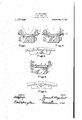
he following isa specification.` ntionwrelatesfito improvements 1n n* "heel `rims of the type 'designed to aticf or other lifesilientz tires and l to` rimsof this type in Whichone vable andr" lersible side ,flanges l sgormedfas to be adapted to ejorm'of y,fsuchkasa olencher 'nggploj ec," g; b aids, when arranged` sition, to receive a different y ire,}such`lis straightfsidedfori Du lo tire, whenarrangedinreverse posionstruction, `which my improvedrc i ereinaltterI Adescribed detail,` I' stronger `rimfwliile kat the"k same 'me materially l reducing th'ei Weight "of the The latter is a point of great o nee,"A as iweigli'tlfon the wheel` oi a hiole is", as is Wellknowm peculiarlyfobiecable@ and also; Where ya number of extra" mstted with` tiresarelto be carried, `as is f common` gpractice, fthe; reduction o eight` of these `extra rims` of yery benefit fw i proved struct tivi/hen` embodied in" arim, comtransyersely, split@ tireeseating por geitha ai these.fflangesinterlock beneath the ori `hooked `flanges on `theledges of baseand serve to locktthe same accidental collap l`unteduponlthenfheel. he accompanying drawings` which o, part of" thisspecificaton, Figure `1 l ransverse` sectional View.;through@` a e fellvffellyband and ,rim, thelatter ag `preferredform I "`gn2 Vis aiview-similar lto Fig; 1,
vnrneLnfWHnnL RIM.
. versely :split `rim b 1 designatesa rimf'base or tire-seating mem-I ure alsohas` the ad-l `ni.baselprovided with one `orf` endless;` tire-.retaining iianges,fthe
se `beforefthe rim" of `my invenhe` tire-retaining vflanges `reversed pianti i the felly fandjrim l, Ifgfj 1.51; Showing .the transf EDSTAES PATENT FFioE AssieNon, `im MssNn AssmNMEN'rs-or ANY,` onyNnwYonK, N. Y., A consona- An TIRE e emanen COMPANY, or Nn ONE-FIFTH To THE UNITED STATES conPoRATioN or NEW Yom i Patented Mar. 2s, i916.
` ase; Fig. 4 isia'view similar to` Fig. l, illustrating a." modified lformot' my invention; Fig. 5 is a `side ele-` vationof the parts shoWniriAFig. 4i, illu'sf` ti'ating the means for locking'the ends fof' fthe-split removable side flange.
cation and in the drawings accompanying the same I. have desxibed 60- andshown certainpreferredr embodrntifhts I of my invention, but these embodiments'are `used merelyifor illustration, and I do' not desire to limit myself to the details thereof any more than as specified in the claims, asniy invention is capable of being. embodied in many otlertstructural forms.
\ Referring-to the drawings in detail, and particularly to 'Figs i, 2 and 3, the numeral.'
"f In y this specifi 70 ber`whici,ias shown in Fig.` 3, is trans-i versely split at the point 2. This rim-base `isprovided-at one or` both edges With inivardly inclined oreilianginglv 'or hooked flanges 3* adapted to engage with, and re?y ,tain upon the rimbase, the endless tire re-` taining ilanges 4. As will `be understood, `in :some cases one endless retaining flange `may be used, other means being provided` toreta'inuthe other side of the tire, such as a Wretaining flange formed integrally with the rimbase f The retaining flanges if are each formed on one side with a groeve 5 shaped to receive e ne of" he projecting beads of a clencher,y tire, as indicated in dotted lines in Fig. 1. The other sideofI each flange is'provided ith" a curved surface or roll 6 adapted t0. engage and support the foot ot a straightsided tire, the roll being for the purposegefoo `preventing the cutting .ofthe tireybfthe `edge 'of the flange in case the tire" becomes deflated Whilein use. It hasliereto'fore `been considered/ necessaryv to have this curvedibeaiing surface `followV the line of the foot of the tire continuously to the sur.` face of the rim base in order to properly support the tire. I have found` however, "that this is not necessary, but that if the tire is supported by the curved surface of "the rim flange near the edge thereof, the [action of the rim and tire is entirelyT satisfacto-ry. I accrrdingly form in the ange a groove? shaped to receive the overhangng or hooked flange 3, the wall 8 of the groove preferably having the same inclination as.
the inner wall ofthe flange 3, sothat it will be closelyv engaged by said flange. 'When the anges are inthe position shown in Fig. 1,`4
therefore, that is, in position `toretain a..
' clencher tire, the wallsk 8 ofthe grooves 7 engage closely against the flanges 3 and the' flanges are held firmly in position u on the rim base. The stress placed upon t e tire- `retaining flanges by an inflated clencher tire is approximately in the directionindicated,
by the arrow 9 in Fig. 1, this direction being,vas willl be seen, approximately-,normal tothei-surface 8 and 'the contacting inner surface ofthe flange ,3. There i's-thus n0 tendency for tlie tire-retaining flange to roll or tiltl over the flange 3, or for it to stretch over it by enlarging in'diameter, as the' stress ris directly toward the Ainner surface ofV theafl'ange and there is .no component parallel ,with such surface, as where a vertical side flange is used. It'will. thusbe seen that itis impossible for the tire-retainingflange Ito escape from the side flange on,
i 'the rim base -without actually shearing ofi' the latter.v 'A much stronger 'structure is what lighter.
thus produced than where a vertical side flange `is used engaging a vertical face o-n 'the tireeretaining flange. 'Atv the same time` a substantial saving in .weight is possible,
asffthe section is reduced by an amount e nale'4 tothe sectional area of the groove 7. jlei' thereon, but it is thel usual practice'to carry tween the tire supporting'slIrfaces-...Q the tire-retaining fianges when mounted in position, to support a ystraight-sided tire, this'v :distance rbeing represented by the dimension b in Fig. A2, shall :be somewhat gre'tvlter than the distance between the edges of the flanges when mounted in "position, to ,retain al clenclier' tire, as indicated by the dimension'v ain Fig.y 1-. ,The dimension b is preferably about one-tenth o J an inch greater than the 75l dimension a.- /The inturned or hooked formation of vthe'lianges 3 hi's another importantffunction. When a, transversely split rim baseer rim has lbeen used heretofore-Iil&j. has ordinarily been -found necessary to pril-,f 8p vide means for locking' the rim against. ac cidental collapse when removed from the felly. The felly will ordinarily prevent w such collapse whenv the rim is mounted l one or lmore of theserims provided with in- Iflated tires" to be substituted upon the felly in case of accident. In such case, of. course,
resultant saving in weight' of the tire-retain# ing. flanges `iswery material, and owing-to the increased strength of the improved structure, a further saving in weight'may be effected by making all of the p artssoine'- When the rim is to be used flanges removed. and replaced -in reverse position, as indicated in Fig. 2. ,When 1n this ,position the toe 10 of each tire-retaining rflange enters the space beneath the corresponding'flange 3 and seats securely therein.
The flanges 3 are preferably given just thev `\the arrow p. ,iper inward inclination toifit the toe of a tire-retaining flange provided with agroove for a clencher bead of standard dimensions The resultant stress placed upon the tireretaining flange oy a straight-sided "re is in approximately the direction -indicated`by.v`1910. I do-not wish 24 in Fig. 2, and, as wil1"be.seen, v such stress-will have a tendency to force the toe of the flange always more firmly into its scat. The outwardly curved edges or rolls 6V of the tire-retaining flangesy give the'sides of .the tire adequate support at the point where support is needed, and also provide rounded surfaces tosupport the tire if it should be necessary to use the same tcmpml rarily while deflated. Itis `also possible to so proportionthe parts that the space beto `"carry av straight-sided tire. the transversely split rim vbase is collapsed and the tii'e-retainin vthe rim, receives no .internal support and must be securely held fromy collapsing under v the pressure of the inflated tire. yWith the construction shownl such collapse is effectually, prevented by" the engagement of. the base portions "ofi the tire-retaining' V.flanges beneath the ,flanges 3. The expansion'of'the inflated rtire holds theseparts in secure engagement, and it is therefore impossible forV .theriiii-base tocolla se..Y The endless flanges also/prevent the un ueexpansion of the rim base, sof'tht no lockingmeans whatever are required for the ends of the latter.
For removably mounting the rim base upon thev wheel felly, any suitablemeans may be used,`the's`e means, however, forming no part of my resent invention. For example; the rim aseV may be provided withl inwardly or downwardly projecting flanges 11 and 12 engaging beveled vsurfaces 13 and 14 of a felly band 15 permanently mounted upon thefelly 16. The beveled surfaces'on the rim ba'seand felly band may be fored into enga ement by means of the rotata le eccentrief` eepers 17,` or by any other suite" able devices. vThe specific construction of the rotatable' keepers is not 'set fprth herein, as thesame is fully described, illustrated and claimed iii-my co-/pending application Serial Number 589,680, lfiled October 29,
,to bqfunderstoo'd, however, as limiting niyself to theuse of these meansin connection with theinvention-'of this case. l i
` In Figs. 4v and 5 I have shownmy invention as'applicd to the modified. form of rim in which the rim base 18 is endless. it being provided at one .side only withan inwardly turned or hooked flange 19 adapted to engage an endless tire-retaining flange 4 of the ,adaptedjftoireceiveA a, `portion of a reversible ,transversely split 'tireeretaining :flange '21 havingthe clencherygrooveQQ in one face `thereof',f and having a rollportion 23o-n ,thelotherixface"thereof for engagement-with a straight-"sided tire. The split flange may be retainedsinits groovel in any suitable manf `nerg-"asjloy means of the lockingdevice shown t in Figa, `which is that n.nllyset forthnxnd claimed in Patent Number 912,537, granted s "toRichardyS Bryant on February 16,1909
. `will beobvious, this-is merely an'illustrationgvof one formr of rim to whichymy" inventionisapplicable. i t
Hiving `thus `described my invention, yI
Avehicle wheel rim. comprising a `rim base` having 'an inwardly hooked flange Qforinedfat one side thereof and a reversible tireretaining flange having one side shaped; toengagea clencher'tire and the other `side shaped to engage a straight-sided tire, the
y basewportion of Asaid" flange having outof lthefsrim base,` theirfcontaeting ssiirfaces` beingnorlnal to` thestress exerted by an wardlygflaringfaces,"one'of the faces lying againstrfthe"ilndensiderof"the hooked portion n fiinflatedctire, the otherfface conforming to l" uthehooked,portion ofl the-rim and having a e toe" seated; `in the hook npon reversal of the tirezretaining flange. Y t e 2.:1A vehi le wheel rim comprising a rim basel having an inwardly hooked flange formed at oneedgethereof 'and a reversible tirefretaining` flange adaptedl to be retained yuponsaidkrim` base by said hooked flange, `said"tire-retaining flange having onetside i shaped to engagea clencher tire and the "`other5gside shapedlyto engage a straightsidedetire and having wedge portions on y i `leach side thereof adapted alternately to fit i inthe recesses beneath said 'hookeddflanga IftheWedgeportions having the saine `inclinationljto the base.
Azireversible tire-retaining flange for `vehicle l, Wheel rims having in one face a clencher groove5, the inner portion of said #side beingformed into a toejl'() having an'` inclined; outer face, the 4other side of said oiflangeuhaving a curved surfaceor `roll d tion are formed at each edge of the rim adapted to supportl astraight-sided tire, said `side` of the flange haviigformedinside of'saidcurved surface a groove/,7, the inner wall 8 of which is inclined t form a `bearing surface, the inclinations of e outer surface of the toe 10and of the wall 8 being equal in degree but opposite in direction'.
4. A vehicle Wheel rim comprising al.
transversely split rini base^having means e for retaining one side -of a tire at one edge t `thereof and having at the other edge thereof fanV inwardly hooked fiange,'and an endless reversible tire-retainingflange mounted on said yrim base, one side of said tire-retaining Iflange having a clencher groove therein, the other side of said flange being formed to engage a straight-sided tire, the base o f said tire-retaining -iflange being 4of dovetail sec- 'SliA tion, thesidefl portions of whichdaave subing bases of dovetail-shaped section,
wedge-shapedside portions of said .e basesl adapted to interchangeably fit into the Wedge-shapedirecesses formed beneath said inclined flanges. e .4
G. A vehicle wheel rim comprising a rim c base. having an inwardly hooked portion at each edge thereof and a pair of similar reversible tire-retaining flanges adapted to en-` gage said hooked portions of the rim base,
each` of ysaid flanges having one side shaped v to engage a clencher. tire and the other side shaped to engage a straight-sided tire, and
having a base portion of dovetail section n the hooked portion` of the rim' base with which the flange'is adapted to engage,
yf 'JAMES n. waennnonsfr;
Witnesses: l EDMU-ND QUINCY Mosns, v Kann S. DIETZ.
, with sides of equal inclination to the` base, i ',said inclination being the same as that of
Priority Applications (1)
| Application Number | Priority Date | Filing Date | Title |
|---|---|---|---|
| US63995311A US1177458A (en) | 1911-07-22 | 1911-07-22 | Vehicle-wheel rim. |
Applications Claiming Priority (1)
| Application Number | Priority Date | Filing Date | Title |
|---|---|---|---|
| US63995311A US1177458A (en) | 1911-07-22 | 1911-07-22 | Vehicle-wheel rim. |
Publications (1)
| Publication Number | Publication Date |
|---|---|
| US1177458A true US1177458A (en) | 1916-03-28 |
Family
ID=3245447
Family Applications (1)
| Application Number | Title | Priority Date | Filing Date |
|---|---|---|---|
| US63995311A Expired - Lifetime US1177458A (en) | 1911-07-22 | 1911-07-22 | Vehicle-wheel rim. |
Country Status (1)
| Country | Link |
|---|---|
| US (1) | US1177458A (en) |
-
1911
- 1911-07-22 US US63995311A patent/US1177458A/en not_active Expired - Lifetime
Similar Documents
| Publication | Publication Date | Title |
|---|---|---|
| US1177458A (en) | Vehicle-wheel rim. | |
| US1088656A (en) | Vehicle wheel-rim. | |
| US969779A (en) | Vehicle-wheel rim. | |
| US1161348A (en) | Wheel-rim. | |
| US800835A (en) | Vehicle-wheel. | |
| US894293A (en) | Vehicle-wheel rim. | |
| US1009445A (en) | Vehicle wheel-rim. | |
| US1160223A (en) | Vehicle-wheel. | |
| US1086330A (en) | Vehicle-wheel. | |
| US1009529A (en) | Vehicle-wheel | |
| US915304A (en) | Vehicle-wheel. | |
| US1601455A (en) | Wheel | |
| US1013387A (en) | Vehicle-rim. | |
| US1136985A (en) | Vehicle wheel-rim. | |
| US1702647A (en) | Wheel rim and tire structupve | |
| US1690999A (en) | Vehicle wheel | |
| US1504689A (en) | Vehicle wheel | |
| US1247684A (en) | Vehicle-wheel. | |
| US1108546A (en) | Rim for wheels. | |
| US1279801A (en) | Spare-tire carrier. | |
| US964462A (en) | Vehicle-wheel. | |
| US1374101A (en) | Wheel | |
| US1166972A (en) | Vehicle-wheel rim. | |
| US1201117A (en) | Vehicle-wheel rim. | |
| US977589A (en) | Fastening device for vehicle-tires. |