US11770011B2 - Processing circuit, method, and electronic device for multiple power supply ports - Google Patents
Processing circuit, method, and electronic device for multiple power supply ports Download PDFInfo
- Publication number
- US11770011B2 US11770011B2 US17/208,598 US202117208598A US11770011B2 US 11770011 B2 US11770011 B2 US 11770011B2 US 202117208598 A US202117208598 A US 202117208598A US 11770011 B2 US11770011 B2 US 11770011B2
- Authority
- US
- United States
- Prior art keywords
- power supply
- bus
- protocol
- supply port
- control module
- Prior art date
- Legal status (The legal status is an assumption and is not a legal conclusion. Google has not performed a legal analysis and makes no representation as to the accuracy of the status listed.)
- Active, expires
Links
Images


Classifications
-
- H—ELECTRICITY
- H02—GENERATION; CONVERSION OR DISTRIBUTION OF ELECTRIC POWER
- H02J—CIRCUIT ARRANGEMENTS OR SYSTEMS FOR SUPPLYING OR DISTRIBUTING ELECTRIC POWER; SYSTEMS FOR STORING ELECTRIC ENERGY
- H02J7/00—Circuit arrangements for charging or depolarising batteries or for supplying loads from batteries
- H02J7/00032—Circuit arrangements for charging or depolarising batteries or for supplying loads from batteries characterised by data exchange
- H02J7/00034—Charger exchanging data with an electronic device, i.e. telephone, whose internal battery is under charge
-
- H02J7/42—
-
- G—PHYSICS
- G06—COMPUTING OR CALCULATING; COUNTING
- G06F—ELECTRIC DIGITAL DATA PROCESSING
- G06F1/00—Details not covered by groups G06F3/00 - G06F13/00 and G06F21/00
- G06F1/26—Power supply means, e.g. regulation thereof
- G06F1/266—Arrangements to supply power to external peripherals either directly from the computer or under computer control, e.g. supply of power through the communication port, computer controlled power-strips
-
- H—ELECTRICITY
- H02—GENERATION; CONVERSION OR DISTRIBUTION OF ELECTRIC POWER
- H02J—CIRCUIT ARRANGEMENTS OR SYSTEMS FOR SUPPLYING OR DISTRIBUTING ELECTRIC POWER; SYSTEMS FOR STORING ELECTRIC ENERGY
- H02J1/00—Circuit arrangements for DC mains or DC distribution networks
- H02J1/10—Parallel operation of DC sources
-
- H—ELECTRICITY
- H02—GENERATION; CONVERSION OR DISTRIBUTION OF ELECTRIC POWER
- H02J—CIRCUIT ARRANGEMENTS OR SYSTEMS FOR SUPPLYING OR DISTRIBUTING ELECTRIC POWER; SYSTEMS FOR STORING ELECTRIC ENERGY
- H02J7/00—Circuit arrangements for charging or depolarising batteries or for supplying loads from batteries
- H02J7/007—Regulation of charging or discharging current or voltage
- H02J7/00712—Regulation of charging or discharging current or voltage the cycle being controlled or terminated in response to electric parameters
- H02J7/00714—Regulation of charging or discharging current or voltage the cycle being controlled or terminated in response to electric parameters in response to battery charging or discharging current
-
- H—ELECTRICITY
- H02—GENERATION; CONVERSION OR DISTRIBUTION OF ELECTRIC POWER
- H02J—CIRCUIT ARRANGEMENTS OR SYSTEMS FOR SUPPLYING OR DISTRIBUTING ELECTRIC POWER; SYSTEMS FOR STORING ELECTRIC ENERGY
- H02J7/00—Circuit arrangements for charging or depolarising batteries or for supplying loads from batteries
- H02J7/007—Regulation of charging or discharging current or voltage
- H02J7/00712—Regulation of charging or discharging current or voltage the cycle being controlled or terminated in response to electric parameters
- H02J7/007182—Regulation of charging or discharging current or voltage the cycle being controlled or terminated in response to electric parameters in response to battery voltage
-
- H02J7/94—
-
- H02J7/96—
-
- H02J13/16—
-
- H—ELECTRICITY
- H02—GENERATION; CONVERSION OR DISTRIBUTION OF ELECTRIC POWER
- H02J—CIRCUIT ARRANGEMENTS OR SYSTEMS FOR SUPPLYING OR DISTRIBUTING ELECTRIC POWER; SYSTEMS FOR STORING ELECTRIC ENERGY
- H02J2207/00—Indexing scheme relating to details of circuit arrangements for charging or depolarising batteries or for supplying loads from batteries
- H02J2207/30—Charge provided using DC bus or data bus of a computer
Definitions
- the present invention relates to the field for supplying power, particularly to a processing circuit, a method, and an electronic device for multiple power supply ports.
- different power supply ports can be used to supply power to the outside, so as to play the role of consuming electricity and/or charging.
- the power supply resources such as the total rated power
- the power supply resources such as the actual output power
- the power supply information e.g., power, voltage, current, etc.
- Each power supply port can supply power under the control of the corresponding port controller. Therefore, the power supply information refers to the specific information mentioned above, and the port controller is the control module mentioned above.
- each control module in order to obtain the power supply information of the other control modules (for example, the operating parameters of the corresponding power supply port), each control module can be connected to the central controller through a digital signal bus such as an IIC bus.
- the central controller can obtain the actual operating parameters (such as power, voltage, etc.) through the control module (such as the port controller).
- dynamic power allocation can be performed based on the obtained operating parameters, and finally the dynamically-allocated results are applied to each power supply port.
- the present invention provides a processing circuit, a method, and an electronic device for multiple power supply ports to solve the problem with high cost of the existing solution.
- a processing circuit for multiple power supply ports which comprises N control modules and a bus, each of the N control modules is correspondingly connected to a power supply port, wherein N is an integer larger than or equal to 2, a communication interface of each of the N control modules is connected to the bus, the bus is connected to a power line ground through a resistor, and the bus is a one-wire bus;
- the control modules transmit value signals to the bus
- the value signals represent values of present power supply information corresponding to the control modules
- the present power supply information represents any one of the operating parameters of the power supply port connected to the control module
- a varied range of a first physical quantity of a bus signal carried by the bus is related to first physical quantities or second physical quantities of all target signals transmitted to the bus;
- control module detects the first quantity of the bus signal carried by the bus through the communication interface and adjusts the operating parameter of the connected power supply port according to the varied range of the detected first physical quantity.
- control module when the control module controls the operating parameter of the connected power supply port according to a varied range of the detected first physical quantity, the control module is configured to:
- control module comprises a detection unit and a protocol processing unit, the detection unit is connected to the communication interface and the protocol processing unit, the detection unit detects and feeds the first physical quantity of the bus signal to the protocol processing unit, the protocol processing unit is connected to the corresponding power supply port, and the protocol processing unit adjusts the operating parameter of the connected power supply port according to the varied range of the detected first physical quantity.
- the protocol processing unit comprises a charging protocol subunit and a communication protocol subunit
- the communication protocol subunit is respectively connected to the detection unit and the charging protocol subunit
- a sum of the second physical quantities is determined and calculated by the communication protocol subunit and fed to the charging protocol subunit or is determined and calculated by the charging protocol subunit
- the charging protocol subunit is connected to the corresponding power supply port
- the charging protocol subunit adjusts the operating parameter of the connected power supply port according to the varied range of the detected first physical quantity.
- control module comprises an output control unit and a protocol processing unit, the output control unit is connected to the communication interface, and the protocol processing unit is connected to the output control unit and the corresponding power supply port;
- the value signal is transmitted from the output control unit of the corresponding control module to the bus, and the value signal is determined by the protocol processing unit of the corresponding control module according to the present information of the power supply port that connected to the protocol processing unit.
- the protocol processing unit comprises a charging protocol subunit and a communication protocol subunit, the communication protocol subunit is respectively connected to the detection unit and the charging protocol subunit, the charging protocol subunit is connected to the corresponding power supply port, and the value signal is determined by the charging protocol subunit and/or the communication protocol subunit of the corresponding control module according to present information determined by the charging protocol subunit.
- the different control modules are arranged in different chips and the chips are USB PD charging protocol chips.
- the first physical quantities are voltage and the second physical quantities are current.
- the operating parameter comprises one of power, voltage, current, and temperature.
- an electronic device comprising the processing circuit for multiple power supply ports and the N power supply ports of the first aspect is provided.
- a processing method for multiple power supply ports applied to one present control module of N control modules each of the N control modules for power management is correspondingly connected to a power supply port, N is an integer larger than or equal to 2, the communication interface of each of the N control modules is connected to the same bus, the bus is connected to a power line ground through a resistor, the bus is a one-wire bus, and the method comprises:
- the method further comprises:
- the first physical quantities are voltage and the second physical quantities are current.
- the operating parameter comprises any one of power, voltage, current, and temperature, etc.
- the present invention provides a processing circuit, a method, and an electronic device for multiple power supply ports. Since each control module is connected to the same one-wire bus through the communication interface.
- the bus signal carried by the bus is influenced and changed by the value signal transmitted from the control module.
- the bus signal is implemented with an analog signal that represents the information represented by the value signal.
- each control module detects the first physical quantity of the bus signal in order to conveniently obtain the information of the other modules instead of uploading the information to a central controller for unified management. As a result, a central processor and a bi-directional communication bus are not arranged, thereby decreasing the cost.
- the present invention inventively proposes that the varied range of the physical quantity of the bus signal is related to the information that needs to be transmitted and corresponds to the same time when communication among multiple modules is implemented by using bus.
- the bus transmits digital signals to achieve communication.
- the present invention simultaneously transmits signals to the bus at any time to reduce the cost of the solution and simplify the circuit and the processing procedure.
- discrete signals are used to represent information during digital signal communication.
- the present invention uses the varied range of the physical quantity of the bus signal to relate with the information.
- the logic of the represented information of the bus signal of the present invention is different from that of the digital signal bus.
- the bus signal is the result of the joint action of all target signals, wherein the result does not represent the information transmitted by a certain module.
- the bus can only use digital signals to respectively transmit information that each module needs to transmit.
- the represented information of the bus signal of the present invention is different from that of the digital signal bus.
- FIG. 1 is a diagram schematically illustrating a processing circuit for multiple power supply ports and the power supply ports according to an embodiment of the present invention
- FIG. 2 is a diagram schematically illustrating a processing circuit for multiple power supply ports and the power supply ports according to an embodiment of the present invention
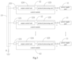
- FIG. 3 is a diagram schematically illustrating a processing circuit for multiple power supply ports and the power supply ports according to an embodiment of the present invention
- FIG. 4 is a diagram schematically illustrating a processing circuit for multiple power supply ports and the power supply ports according to an embodiment of the present invention
- FIG. 5 is a diagram schematically illustrating a circuit for determining broadcast power according to an embodiment of the present invention
- FIG. 6 is a flowchart of a processing method for multiple power supply ports according to an embodiment of the present invention.
- FIG. 7 is a flowchart of a processing method for multiple power supply ports according to an embodiment of the present invention.
- FIG. 8 is a flowchart of a processing method for multiple power supply ports according to an embodiment of the present invention.
- FIG. 1 is a diagram schematically illustrating a processing circuit for multiple power supply ports and the power supply ports according to an embodiment of the present invention.
- FIG. 2 is a diagram schematically illustrating a processing circuit for multiple power supply ports and the power supply ports according to an embodiment of the present invention.
- FIG. 3 is a diagram schematically illustrating a processing circuit for multiple power supply ports and the power supply ports according to an embodiment of the present invention.
- FIG. 4 is a diagram schematically illustrating a processing circuit for multiple power supply ports and the power supply ports according to an embodiment of the present invention.
- the processing circuit for multiple power supply ports includes N control modules 12 and a bus 13 .
- Each of the N control modules 12 is correspondingly connected to a power supply port 11 , wherein N is an integer larger than or equal to 2.
- the communication interface 121 of each of the N control modules 12 is connected to the bus 13 .
- the bus 13 is connected to the power line ground through a resistor R.
- the bus is a one-wire bus.
- the power supply port 11 is a port with any structure. As long as the port can output power to the outside, the demands for consuming power or charging external devices are included within the scope of the embodiment.
- the power supply port can be a USB port of Type-C, Type-A, or Type-B standard. In other embodiments, other ports or the lightning ports can be used.
- the control module 12 is directly or indirectly connected to the power supply port 11 . It can be understood that the direct or indirect connection for the power supply information of the power supply port obtained by the corresponding control module is included within the scope of the embodiment.
- the power supply information of the power supply port is controlled and determined by the control module.
- the control module can obtain its power supply information.
- the power supply information of the power supply port is detected by the control module through the related circuit.
- the communication interface 121 of each control module 12 is connected to the bus 13 .
- the bus 13 is connected to the power line ground through the bus resistor R.
- the bus 13 is a one-wire bus.
- the bus 13 is directly connected to a bus power.
- the bus 13 is connected to the bus power through another bus resistor.
- the one-wire bus has a current-flowing path along a single direction, wherein the current can flow from a terminal far from the power line ground (e.g., the power terminal) to the power line ground.
- the method of forming the circuit and the metal wires, the method of wiring the metal wires, and the size and the number of the metal wires are included within the scope of the embodiment.
- the one-wire bus has lower cost.
- the embodiment arranges the control module 12 and the corresponding processing procedure based on the one-wire bus, such that the control module 12 obtains the power supply information of the other control modules 12 . Simultaneously, due to the one-wire bus, the value signal of any control module can have an effect on the bus. Thus, the other modules can accurately know the effect.
- control module 12 can transmit the value signal to the bus 13 through the communication interface 121 , such that the first physical quantity of the bus signal correspondingly changes.
- the varied range of the first physical quantity of the bus signal carried by the bus is related to the first physical quantities or second physical quantities of all target signals transmitted to the bus.
- the control module 12 detects the first quantity of the bus signal carried by the bus 13 through the communication interface 121 and adjusts the operating parameter of the connected power supply port according to the varied range of the detected first physical quantity.
- the value signal represents the value of the present power supply information of the power supply port connected to the corresponding control module.
- the value signal is outputted such that the first physical quantity correspondingly changes in order to conveniently identify the power supply information and the other related information.
- the present power supply information represents one of the operating parameters of the power supply port connected to the present main module.
- the operating parameter includes, for example, power, voltage, current, temperature, etc.
- the value of the value signal may be the corresponding value of power, voltage, current, or temperature. Alternatively, the embodiment uses other parameters and the corresponding values.
- each control module is connected to the same one-wire bus through the communication interface and the bus signal carried by the bus is influenced and changed by the value signal transmitted by the main module.
- the bus signal represents the power supply information represented by the value signal.
- each control module detects the first physical quantity of the bus signal in order to conveniently obtain the power supply information of the power supply port controlled by the other modules instead of uploading the information to a central controller for unified management. As a result, a central processor and a bi-directional communication bus are not arranged, thereby effectively decreasing the cost.
- a part of the conventional technology can also use a bi-directional communication circuit to connect to two control modules, such that the control modules communicate with each other to obtain power supply information.
- the conventional technology does not support the situation for 3-to-3 power supply ports.
- the present invention can support the situation for 3-to-3 power supply ports. Since the bi-directional communication circuit is not arranged, the cost can be reduced.
- control module when the control module adjusts the operating parameter of the connected power supply port according to the varied range of the detected first physical quantity, the control module is configured to:
- the first physical quantities may be voltage and the second physical quantities may be current.
- the second physical quantities may be voltage or power and first physical quantities may be power.
- the sum of the present power supply information and the adjusted operating parameter may be the same parameter.
- the power of the connected power supply port is adjusted based on the sum of power of the other control modules.
- the sum of the present power supply information and the adjusted operating parameter may be different parameters.
- the voltage and current of the connected power supply port are adjusted based on the sum of power of the other control modules.
- the power of the connected power supply port is adjusted based on the sum of the temperature of the other control modules.
- I(n) represents a current outputted from the nth control module to the bus, namely the second physical quantity outputted from nth control module to the bus;
- I(total) represents the sum of currents outputted from all the modules to the bus, namely the sum of the second physical quantities of the signals outputted by all the modules;
- V represents the voltage of the presently-detected bus signal, namely the first physical quantity of the bus signal
- R represents the resistance of the bus resistor.
- the current flowing through the bus resistor is equal to the sum of currents of output currents of all the modules.
- I(total) is obtained based on the foregoing equation.
- the operating parameter of the connected power supply port is adjusted based on the sum of the present power supply information of the other control modules. For example, if the sum of the present power supply information is the sum of power, the power of the connected power supply port is adjusted based on the sum of power. For example, the sum of power of all the power supply ports can reach the maximum value. Alternatively, the sum of power of all the power supply ports is less than a secure power threshold.
- I(others) may represent the sum of the present power supply information of the other control modules. Then, I(others) can be converted into the specific value of the sum of the power supply information. In other situations, I(total) or its converted specific value can be used without separating from I(k). Besides, the statistical information such as the mean value is calculated based on I(others), I(total), or their converted specific values. The other processing requirements are satisfied based on I(others) and I(total) in different periods or their converted specific value.
- the control module 12 includes a detection unit 122 and a protocol processing unit 123 .
- the detection unit 122 connected to the communication interface 121 and the protocol processing unit 123 , detects and feeds the first physical quantity of the bus signal to the protocol processing unit 123 .
- the protocol processing unit 123 is connected to the corresponding power supply port.
- the protocol processing unit 123 adjusts the operating parameter of the connected power supply port according to the varied range of the first physical quantity detected.
- the detection unit 122 will be a voltage detection unit.
- the protocol processing unit 123 may include a charging protocol subunit 1232 and a communication protocol subunit 1231 .
- the communication protocol subunit 1231 is respectively connected to the detection unit 122 and the charging protocol subunit 1232 .
- the sum of the second physical quantities is determined by the communication protocol subunit 1231 and fed to the charging protocol subunit 1232 .
- the charging protocol subunit 1232 is connected to the corresponding power supply port 11 .
- the charging protocol subunit 1232 adjusts the operating parameter of the connected power supply port 11 according to the varied range of the detected first physical quantity.
- the charging protocol subunit 1232 may be a circuit subunit for processing based on the charging protocol.
- the charging protocol subunit 1232 may be a circuit subunit in the existing control module, such as a circuit subunit based on the USB PD protocol.
- the communication protocol subunit 1231 may be a circuit subunit for processing based on the communication protocol.
- the charging protocol subunit will not be used or another circuit will be used.
- the control module 12 includes an output control unit 124 and a protocol processing unit 123 .
- the output control unit 124 is connected to the communication interface 121 .
- the protocol processing unit 123 is connected to the output control unit 124 and the corresponding power supply port 11 .
- the value signal is transmitted from the output control unit 124 of the corresponding control module to the bus 23 .
- the value signal is determined by the protocol processing unit 123 of the corresponding control module according to present information of the connected power supply port 11 .
- the output control unit 124 may be a current control unit.
- the protocol processing unit 123 includes a charging protocol subunit 1232 and a communication protocol subunit 1231 .
- the communication protocol subunit 1231 is respectively connected to the output control unit 124 and the charging protocol subunit 1232 .
- the charging protocol subunit 1232 is connected to the corresponding power supply port 11 .
- the value signal is determined by the charging protocol subunit 1232 and/or the communication protocol subunit 1231 of the corresponding control module according to the present information determined by the charging protocol subunit 1232 .
- the charging protocol subunit 1232 is a circuit subunit for processing based on the charging protocol.
- the charging protocol subunit 1232 may be a circuit subunit in the existing control module, such as a circuit subunit based on the USB PD protocol.
- the communication protocol subunit 1231 may be a circuit subunit for processing based on the communication protocol.
- the charging protocol subunit will not be used or another circuit will be used.
- control modules may be arranged in different chips.
- the chip may be a USB PD charging protocol chip or another charging protocol chip. Depending on the different ports used, the corresponding chip can adopt different charging protocols.
- FIG. 5 is a diagram schematically illustrating a circuit for determining broadcast power according to an embodiment of the present invention.
- the process of determining power supply information including power as the operating parameter is taken as an example for detailed explanation.
- the other processes of determining the other operating parameters such as voltage and current can also be understood with reference to this process.
- the value of the value signal generated by the chip is power.
- the chip needs to obtain the power supply information of the other chips, namely broadcast power.
- the voltage detection unit 1221 detects the voltage signal VS of the bus XPLINK.
- all the chips Chip(i) can obtain the sum of physical quantities such as voltage, current, or temperature of the other chips interconnected to the bus.
- an electronic device including the processing circuit for multiple power supply ports and the N power supply ports of the foregoing embodiments.
- the electronic device may be a charging device dedicated to charging, such as a portable battery.
- the electronic device may also be a power supply device dedicated to supplying power, such as a power socket.
- the electronic device may be equipped with multiple power supply ports and not dedicated to supplying power and charging, such as a computer, a camera, a mobile phone, a household appliance, industrial equipment, etc.
- the electronic device can supply power to the equipment connected to the power supply port of the electronic device to satisfy requirements for power consumption or charging. It can be seen that an electronic device that has any functions and meets the description of the embodiment is included within the scope of the embodiment.
- the processing circuit for multiple power supply ports and the electronic device are provided. Since each control module is connected to the same one-wire bus through the communication interface.
- the bus signal carried by the bus is influenced and changed by the value signal transmitted from the control module.
- the bus signal is implemented with an analog signal that represents the information represented by the value signal.
- each control module detects the first physical quantity of the bus signal in order to conveniently obtain the information of the other modules instead of uploading the information to a central controller for unified management.
- a central processor and a bi-directional communication bus are not arranged, thereby decreasing the cost.
- FIG. 6 is a flowchart of a processing method for multiple power supply ports according to an embodiment of the present invention.
- FIG. 7 is a flowchart of a processing method for multiple power supply ports according to an embodiment of the present invention.
- FIG. 8 is a flowchart of a processing method for multiple power supply ports according to an embodiment of the present invention.
- the method can be applied to the processing circuit for multiple power supply ports and one present control module of N control modules of the electronic device.
- Each of the N control modules for power management is correspondingly connected to a power supply port, wherein N is an integer larger than or equal to 2.
- the communication interface of each of the N control modules is connected to the same bus.
- the bus is connected to a power line ground through a resistor.
- the bus is a one-wire bus.
- the method includes:
- Step S 201 if the result of Step S 201 is yes, performing Step S 202 and transmitting value signals to a bus.
- the value signals are transmitted to the bus when the present control module needs to transmit the present power supply information to the other control modules.
- the value signal represents the value of the present power supply information corresponding to the present control module.
- the present power supply information represents an operating parameter of the power supply port connected to the corresponding control module.
- the varied range of the first physical quantity is related to the first physical quantities or the second physical quantities of the target signals transmitted to the bus.
- the method includes:
- the first physical quantity of the bus signal carried by the bus is detected through the communication interface and the operating parameter of the connected power supply port is adjusted according to the varied range of the detected first physical quantity when the present control module needs to obtain the present power supply information transmitted by the other control modules.
- Step S 205 may include:
- each control module Since each control module is connected to the same one-wire bus through the communication interface.
- the bus signal carried by the bus is influenced and changed by the value signal transmitted from the control module.
- the bus signal is implemented with an analog signal that represents the information represented by the value signal.
- each control module detects the first physical quantity of the bus signal in order to conveniently obtain the information of the other modules instead of uploading the information to a central controller for unified management. As a result, a central processor and a bi-directional communication bus are not arranged, thereby decreasing the cost.
- the foregoing program can be stored in a computer readable storage medium.
- the foregoing storage medium includes a ROM, a RAM, a magnetic disk, an optical disk, or a media that can store program codes.
Landscapes
- Engineering & Computer Science (AREA)
- General Engineering & Computer Science (AREA)
- Theoretical Computer Science (AREA)
- Power Engineering (AREA)
- Computer Hardware Design (AREA)
- Physics & Mathematics (AREA)
- General Physics & Mathematics (AREA)
- Power Sources (AREA)
Abstract
Description
-
- when obtaining present information transmitted by the other control modules, detecting a first physical quantity of the bus signal carried by the bus through the communication interface;
- when transmitting present power supply information to the other control modules, transmitting a value signal to the bus, the value signals represent values of present power supply information of the control modules, and a varied range of a first physical quantity of a bus signal carried by the bus is related to first physical quantities or second physical quantities of all target signals transmitted to the bus;
- the present power supply information represents any one of the operating parameters of the power supply port connected to the control module.
-
- determining the sum of second physical quantities of signals transmitted from other control modules connected to the bus to the bus and using the sum to represent a sum of present power supply information of other control modules according to the first physical quantity of the bus signal.
-
- Description of the reference numerals:
- 11—power supply port;
- 12—control module;
- 121—communication interface;
- 122—detection unit;
- 1221—voltage detection unit;
- 123—protocol processing unit;
- 124—output control unit;
- 13—bus.
-
- S203: determining whether the present control module needs to obtain the present power supply information transmitted by the other control modules;
- if the result of Step S203 is yes, performing Step S204 of detecting the first physical quantity of a bus signal carried by the bus through the communication interface;
- S205: adjusting the operating parameter of the connected power supply port according to the varied range of the detected first physical quantity.
-
- S2051: determining the sum of second physical quantities of signals transmitted from the other control modules connected to the bus to the bus and using the sum to represent the sum of present power supply information of the other control modules according to the first physical quantity of the bus signal;
- S2052: adjusting the operating parameter of the connected power supply port according to the sum of present power supply information of the other control modules.
Claims (20)
Priority Applications (1)
| Application Number | Priority Date | Filing Date | Title |
|---|---|---|---|
| US17/208,598 US11770011B2 (en) | 2021-03-22 | 2021-03-22 | Processing circuit, method, and electronic device for multiple power supply ports |
Applications Claiming Priority (1)
| Application Number | Priority Date | Filing Date | Title |
|---|---|---|---|
| US17/208,598 US11770011B2 (en) | 2021-03-22 | 2021-03-22 | Processing circuit, method, and electronic device for multiple power supply ports |
Publications (2)
| Publication Number | Publication Date |
|---|---|
| US20220302720A1 US20220302720A1 (en) | 2022-09-22 |
| US11770011B2 true US11770011B2 (en) | 2023-09-26 |
Family
ID=83284385
Family Applications (1)
| Application Number | Title | Priority Date | Filing Date |
|---|---|---|---|
| US17/208,598 Active 2041-10-25 US11770011B2 (en) | 2021-03-22 | 2021-03-22 | Processing circuit, method, and electronic device for multiple power supply ports |
Country Status (1)
| Country | Link |
|---|---|
| US (1) | US11770011B2 (en) |
Families Citing this family (1)
| Publication number | Priority date | Publication date | Assignee | Title |
|---|---|---|---|---|
| CN117406847B (en) * | 2023-12-14 | 2024-04-09 | 浙江地芯引力科技有限公司 | Chip, power supply circuit thereof and electronic equipment |
Citations (4)
| Publication number | Priority date | Publication date | Assignee | Title |
|---|---|---|---|---|
| US20110278921A1 (en) * | 2010-05-11 | 2011-11-17 | Erik Jon Fretheim | Adaptive Power Bus |
| US20150177813A1 (en) * | 2013-12-23 | 2015-06-25 | Dell, Inc. | Global throttling of computing nodes in a modular, rack-configured information handling system |
| US20200225721A1 (en) * | 2019-01-15 | 2020-07-16 | Dell Products, Lp | System and method for dynamically identifying a power adaptor power rating based on operating conditions |
| US20210223838A1 (en) * | 2020-01-16 | 2021-07-22 | Alpha And Omega Semiconductor (Cayman) Ltd. | Multi-port power delivery system and related control method |
-
2021
- 2021-03-22 US US17/208,598 patent/US11770011B2/en active Active
Patent Citations (4)
| Publication number | Priority date | Publication date | Assignee | Title |
|---|---|---|---|---|
| US20110278921A1 (en) * | 2010-05-11 | 2011-11-17 | Erik Jon Fretheim | Adaptive Power Bus |
| US20150177813A1 (en) * | 2013-12-23 | 2015-06-25 | Dell, Inc. | Global throttling of computing nodes in a modular, rack-configured information handling system |
| US20200225721A1 (en) * | 2019-01-15 | 2020-07-16 | Dell Products, Lp | System and method for dynamically identifying a power adaptor power rating based on operating conditions |
| US20210223838A1 (en) * | 2020-01-16 | 2021-07-22 | Alpha And Omega Semiconductor (Cayman) Ltd. | Multi-port power delivery system and related control method |
Also Published As
| Publication number | Publication date |
|---|---|
| US20220302720A1 (en) | 2022-09-22 |
Similar Documents
| Publication | Publication Date | Title |
|---|---|---|
| US10860074B2 (en) | Power supply system and semiconductor device used for the same | |
| EP3413426B1 (en) | Hub | |
| CA2940788C (en) | Power over ethernet method and device | |
| TWI530112B (en) | Power line communications device, power line communications system, and monitoring power method thereof | |
| US8415826B2 (en) | Power outlet apparatus with multiple sockets detection, and detection method thereof | |
| US9831913B2 (en) | Power source equipment and power supplying method for power over ethernet system | |
| US20160105038A1 (en) | Adapter, portable electronic device and charge control method thereof | |
| US20200228353A1 (en) | Energy-saving power sourcing method, power sourcing equipment, and powered device | |
| US10374265B2 (en) | Communication terminating resistance automatic setting method of energy storage system | |
| US9712897B2 (en) | Communication device, receiving device, and communication system for transmitting information in daisy chain network | |
| US8941342B2 (en) | Integrated servo system | |
| TWI633418B (en) | Supply voltage control module, circuit including the same and related methods | |
| WO2017152631A1 (en) | Power-supply control device, power supply system, load, and base station | |
| CN103399251A (en) | USB communication line detection device | |
| US9923368B2 (en) | Electronic apparatus and driving control method thereof | |
| CN108667082A (en) | A kind of line loss compensation method, apparatus and system | |
| US11770011B2 (en) | Processing circuit, method, and electronic device for multiple power supply ports | |
| CN106888056A (en) | Power adjustment method and device for visible light communication | |
| CN110941538A (en) | Processing circuit and method for multiple power supply ports and electronic equipment | |
| CN211264302U (en) | Processing circuit and electronic equipment for multiple power supply ports | |
| CN111010326B (en) | Multi-module communication system, processing circuit and method of power supply port and electronic equipment | |
| US20200285301A1 (en) | Server system, server device and power management method for server device | |
| US10719111B2 (en) | Multiport connector and power control method | |
| US9735837B2 (en) | Method and wireless charging receiver capable of automatically detecting information of wireless power transmitter to limit maximum charging current provided for portable device | |
| CN103777666A (en) | AVS master slave |
Legal Events
| Date | Code | Title | Description |
|---|---|---|---|
| FEPP | Fee payment procedure |
Free format text: ENTITY STATUS SET TO UNDISCOUNTED (ORIGINAL EVENT CODE: BIG.); ENTITY STATUS OF PATENT OWNER: SMALL ENTITY |
|
| AS | Assignment |
Owner name: SHENZHEN WING SEMICONDUCTOR CO., LTD., CHINA Free format text: ASSIGNMENT OF ASSIGNORS INTEREST;ASSIGNORS:LIU, WENJUN;CHEN, SONGTAO;REEL/FRAME:055687/0129 Effective date: 20210312 |
|
| FEPP | Fee payment procedure |
Free format text: ENTITY STATUS SET TO SMALL (ORIGINAL EVENT CODE: SMAL); ENTITY STATUS OF PATENT OWNER: SMALL ENTITY |
|
| STPP | Information on status: patent application and granting procedure in general |
Free format text: DOCKETED NEW CASE - READY FOR EXAMINATION |
|
| STPP | Information on status: patent application and granting procedure in general |
Free format text: NON FINAL ACTION MAILED |
|
| STPP | Information on status: patent application and granting procedure in general |
Free format text: RESPONSE TO NON-FINAL OFFICE ACTION ENTERED AND FORWARDED TO EXAMINER |
|
| STPP | Information on status: patent application and granting procedure in general |
Free format text: PUBLICATIONS -- ISSUE FEE PAYMENT RECEIVED |
|
| STPP | Information on status: patent application and granting procedure in general |
Free format text: PUBLICATIONS -- ISSUE FEE PAYMENT VERIFIED |
|
| STCF | Information on status: patent grant |
Free format text: PATENTED CASE |