US11768180B1 - Method for ultrasonic guided wave quantitative imaging in form of variable array - Google Patents
Method for ultrasonic guided wave quantitative imaging in form of variable array Download PDFInfo
- Publication number
- US11768180B1 US11768180B1 US18/176,439 US202318176439A US11768180B1 US 11768180 B1 US11768180 B1 US 11768180B1 US 202318176439 A US202318176439 A US 202318176439A US 11768180 B1 US11768180 B1 US 11768180B1
- Authority
- US
- United States
- Prior art keywords
- denoting
- green
- function
- guided wave
- probes
- Prior art date
- Legal status (The legal status is an assumption and is not a legal conclusion. Google has not performed a legal analysis and makes no representation as to the accuracy of the status listed.)
- Active
Links
Images


Classifications
-
- G—PHYSICS
- G01—MEASURING; TESTING
- G01N—INVESTIGATING OR ANALYSING MATERIALS BY DETERMINING THEIR CHEMICAL OR PHYSICAL PROPERTIES
- G01N29/00—Investigating or analysing materials by the use of ultrasonic, sonic or infrasonic waves; Visualisation of the interior of objects by transmitting ultrasonic or sonic waves through the object
- G01N29/04—Analysing solids
- G01N29/06—Visualisation of the interior, e.g. acoustic microscopy
- G01N29/0654—Imaging
- G01N29/069—Defect imaging, localisation and sizing using, e.g. time of flight diffraction [TOFD], synthetic aperture focusing technique [SAFT], Amplituden-Laufzeit-Ortskurven [ALOK] technique
-
- G—PHYSICS
- G01—MEASURING; TESTING
- G01N—INVESTIGATING OR ANALYSING MATERIALS BY DETERMINING THEIR CHEMICAL OR PHYSICAL PROPERTIES
- G01N29/00—Investigating or analysing materials by the use of ultrasonic, sonic or infrasonic waves; Visualisation of the interior of objects by transmitting ultrasonic or sonic waves through the object
- G01N29/04—Analysing solids
- G01N29/06—Visualisation of the interior, e.g. acoustic microscopy
- G01N29/0654—Imaging
-
- G—PHYSICS
- G01—MEASURING; TESTING
- G01N—INVESTIGATING OR ANALYSING MATERIALS BY DETERMINING THEIR CHEMICAL OR PHYSICAL PROPERTIES
- G01N29/00—Investigating or analysing materials by the use of ultrasonic, sonic or infrasonic waves; Visualisation of the interior of objects by transmitting ultrasonic or sonic waves through the object
- G01N29/04—Analysing solids
- G01N29/041—Analysing solids on the surface of the material, e.g. using Lamb, Rayleigh or shear waves
-
- G—PHYSICS
- G01—MEASURING; TESTING
- G01N—INVESTIGATING OR ANALYSING MATERIALS BY DETERMINING THEIR CHEMICAL OR PHYSICAL PROPERTIES
- G01N29/00—Investigating or analysing materials by the use of ultrasonic, sonic or infrasonic waves; Visualisation of the interior of objects by transmitting ultrasonic or sonic waves through the object
- G01N29/44—Processing the detected response signal, e.g. electronic circuits specially adapted therefor
- G01N29/4481—Neural networks
-
- G—PHYSICS
- G01—MEASURING; TESTING
- G01N—INVESTIGATING OR ANALYSING MATERIALS BY DETERMINING THEIR CHEMICAL OR PHYSICAL PROPERTIES
- G01N29/00—Investigating or analysing materials by the use of ultrasonic, sonic or infrasonic waves; Visualisation of the interior of objects by transmitting ultrasonic or sonic waves through the object
- G01N29/44—Processing the detected response signal, e.g. electronic circuits specially adapted therefor
- G01N29/46—Processing the detected response signal, e.g. electronic circuits specially adapted therefor by spectral analysis, e.g. Fourier analysis or wavelet analysis
-
- G—PHYSICS
- G06—COMPUTING OR CALCULATING; COUNTING
- G06T—IMAGE DATA PROCESSING OR GENERATION, IN GENERAL
- G06T7/00—Image analysis
- G06T7/0002—Inspection of images, e.g. flaw detection
- G06T7/0004—Industrial image inspection
-
- G—PHYSICS
- G01—MEASURING; TESTING
- G01N—INVESTIGATING OR ANALYSING MATERIALS BY DETERMINING THEIR CHEMICAL OR PHYSICAL PROPERTIES
- G01N2291/00—Indexing codes associated with group G01N29/00
- G01N2291/01—Indexing codes associated with the measuring variable
- G01N2291/015—Attenuation, scattering
-
- G—PHYSICS
- G01—MEASURING; TESTING
- G01N—INVESTIGATING OR ANALYSING MATERIALS BY DETERMINING THEIR CHEMICAL OR PHYSICAL PROPERTIES
- G01N2291/00—Indexing codes associated with group G01N29/00
- G01N2291/02—Indexing codes associated with the analysed material
- G01N2291/023—Solids
- G01N2291/0234—Metals, e.g. steel
-
- G—PHYSICS
- G01—MEASURING; TESTING
- G01N—INVESTIGATING OR ANALYSING MATERIALS BY DETERMINING THEIR CHEMICAL OR PHYSICAL PROPERTIES
- G01N2291/00—Indexing codes associated with group G01N29/00
- G01N2291/02—Indexing codes associated with the analysed material
- G01N2291/028—Material parameters
- G01N2291/02854—Length, thickness
-
- G—PHYSICS
- G01—MEASURING; TESTING
- G01N—INVESTIGATING OR ANALYSING MATERIALS BY DETERMINING THEIR CHEMICAL OR PHYSICAL PROPERTIES
- G01N2291/00—Indexing codes associated with group G01N29/00
- G01N2291/02—Indexing codes associated with the analysed material
- G01N2291/028—Material parameters
- G01N2291/0289—Internal structure, e.g. defects, grain size, texture
-
- G—PHYSICS
- G01—MEASURING; TESTING
- G01N—INVESTIGATING OR ANALYSING MATERIALS BY DETERMINING THEIR CHEMICAL OR PHYSICAL PROPERTIES
- G01N2291/00—Indexing codes associated with group G01N29/00
- G01N2291/04—Wave modes and trajectories
- G01N2291/042—Wave modes
- G01N2291/0427—Flexural waves, plate waves, e.g. Lamb waves, tuning fork, cantilever
-
- G—PHYSICS
- G01—MEASURING; TESTING
- G01N—INVESTIGATING OR ANALYSING MATERIALS BY DETERMINING THEIR CHEMICAL OR PHYSICAL PROPERTIES
- G01N2291/00—Indexing codes associated with group G01N29/00
- G01N2291/10—Number of transducers
- G01N2291/106—Number of transducers one or more transducer arrays
-
- G—PHYSICS
- G06—COMPUTING OR CALCULATING; COUNTING
- G06T—IMAGE DATA PROCESSING OR GENERATION, IN GENERAL
- G06T2207/00—Indexing scheme for image analysis or image enhancement
- G06T2207/30—Subject of image; Context of image processing
- G06T2207/30108—Industrial image inspection
-
- G—PHYSICS
- G06—COMPUTING OR CALCULATING; COUNTING
- G06T—IMAGE DATA PROCESSING OR GENERATION, IN GENERAL
- G06T7/00—Image analysis
- G06T7/40—Analysis of texture
Definitions
- the present disclosure relates to the technical field of ultrasonic non-destructive testing, in particular to a method for ultrasonic guided wave quantitative imaging in a form of variable array.
- Lamb wave features long propagation distance and dispersion in a metal plate structure, and is quite sensitive to the change of plate thickness. Lamb wave has been applied in many fields such as liquid storage tank detection, oil and gas pipeline detection, and aircraft skin detection in the chemical industry. Therefore, ultrasonic guided wave non-destructive testing technology based on lamb wave has become a research hotspot in the field of non-destructive testing.
- the objectives of the present disclosure are to overcome the defects in the prior art and provide a method for ultrasonic guided wave quantitative imaging in a form of variable array.
- imaging of the thickness of a tested region may be performed with scattered field experimental signals acquired by an ultrasonic transducer, so as to achieve quantitative evaluation.
- a method for ultrasonic guided wave quantitative imaging in a form of variable array includes:
- U ( t ) U ( in ) + C ⁇ O ⁇ U ( t )
- U ( s ) D ⁇ O ⁇ U ( t ) by a method of moments, U (t) denoting a total field, U (in) denoting an incident field, U (s) denoting a scattered field, C denoting a Green's function of a zero-defect aluminum plate, O denoting an objective function to be solved, D denoting a Green's function of a defective aluminum plate;
- the selecting, based on data of a measured scattered field, acquisition arrays with different numbers of probes as an initial input, and selecting different solution algorithms for the acquisition arrays with different numbers of probes includes:
- the selecting to construct a single-layer neural network algorithm to solve the unknown vector to be solved includes:
- T 1 2 ⁇ ⁇ ⁇ k ⁇ 2 2 , ⁇ ⁇ k ⁇ 2 2 denoting the square of a 2-norm of ⁇ k ⁇ , X 1 denoting a weight of a neural network training, X 1 k denoting a weight of a kth neural network training;
- the selecting a principal component analysis algorithm to solve the unknown vector to be solved includes:
- the modifying the Green's functions by variable born approximation for continuous iterations to approximate a true solution includes:
- the objective function needs to be further processed to facilitate imaging and quantitative evaluation, specifically including: based on an analytical expression form
- O ⁇ ( r n ) k 0 2 [ ( c 0 c ⁇ ( r n ) ) 2 - 1 ] of the objective function, performing correspondence on the objective function O k (r n ) to a phase velocity c(r n ), obtaining actual aluminum plate thickness distribution by combining a lamb wave dispersion curve, and performing imaging and quantitative evaluation based on a thickness value of each grid point, k 0 denoting the wave number of A0 mode lamb waves of the zero-defect aluminum plate at a selected center frequency, c 0 denoting the phase velocity of the zero-defect aluminum plate, c(r n ) denoting a phase velocity of a grid point r n in a tested region.
- the nonlinear lippmann-Schwinger equation is converted into the form of linear matrix summation, and the solution method is variable born approximation iterations, which can continuously correct the Green's functions to approximate the true solution.
- the method can be quickly implemented by programming.
- the number of the probes can be selected based on the testing accuracy. Since different arrays obtain different numbers of scattered fields, an equation is under-determined in the case of sparse arrays, the equation is over-determined in the case of dense arrays, and suitable algorithms are selected for solutions.
- the method has strict mathematical logics and rigorous derivation, can allow experimental verification and realize the quantitative evaluation of non-destructive testing, and can be widely used in practical guided wave testing applications of industrial non-destructive testing.
- FIG. 1 is a schematic structural diagram of an array for obtaining acquired signals by adjusting the number of probes of the array and adopting a one-transmitting and multi-receiving form;
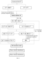
- FIG. 2 is a schematic flow diagram of a method according to the present disclosure
- FIG. 3 is a diagram illustrating actual defects of a tested aluminum plate according to the present disclosure
- FIG. 4 are experimental imaging effect diagrams of an 8-probe array, a 16-probe array, a 32-probe array, and a 64-probe array according to the present disclosure.
- FIG. 5 is a graph of a defect trend quantitatively evaluated by intercepting a line segment passing a center according to a method of the present disclosure.
- the present disclosure relates to a method for ultrasonic guided wave quantitative imaging in a form of variable array.
- the method includes: Set up an ultrasonic guided wave non-destructive testing platform, and design a circular sensor array including different numbers of probes. Acquire guided wave scattered field signals through the array with one probe for excitation and the other probes for receiving by changing an excitation position to repeat operations. Invert the acquired scattered field signals through a lippmann-Schwinger equation in the form of linear summation, an inversion algorithm being a variable born approximation iteration algorithm.
- the inversion algorithm corresponds to different solution methods in different arrays: the inversion algorithm corresponds to a neural network algorithm when in an under-determined form, and corresponds to a principal component analysis algorithm when in an over-determined form. Map an objective function obtained by a final result of the inversion algorithm to obtain a thickness value of each grid point in an imaging region, and perform imaging based on the thickness values. Therefore, the effect of quantitative evaluation is achieved.
- the ultrasonic guided wave non-destructive testing platform includes a PC, a signal generator, a power amplifier, a guided wave probe, an aluminum plate to be tested, a preamplifier, and an acquisition card.
- the PC is equipped with labview for modulation of an acquired signal, a digital signal is transferred to the signal generator for digital-to-electrical conversion, a voltage signal is amplified by the power amplifier and transferred to the guided wave probe to excite a trigger signal, the trigger signal is then received by acquisition probes, transferred to the preamplifier to be amplified once at a receiving end, and transmitted to the acquisition card, and the acquired signal is displayed and stored by the PC.
- a specific testing target is an aluminum plate with an unknown defect.
- the thickness of the aluminum plate is 3 mm, and the testing diameter is 40 cm.
- a certain number of transducers (sensor probes) are arranged on the testing circumference.
- a circular array in a one-transmitting and multi-receiving form is adopted, and probes of any number may be provided.
- a total of four arrays are provided in the design of the present disclosure, which are an 8-probe array, a 16-probe array, a 32-probe array, and a 64-probe array respectively.
- the four arrays may acquire 56 groups of signals, 240 groups of signals, 992 groups of signals, and 4032 groups of signals respectively. Based on array requirements, if m probes are provided, m(m ⁇ 1) groups of acquired signals may be obtained.
- the acquisition probe in the array may be an air-coupled guided wave probe.
- the excitation frequency is 200 k
- an oblique incidence angle is 9.74 degrees through calculation based on the snell law
- an excitation mode is a lamb wave A0 mode.
- a processing method includes the following steps:
- the core of the present disclosure lies in the linear lippmann-Schwinger equation in the form as:
- variable born approximation iteration algorithm is used for solving the objective function in the linear lippmann-Schwinger equation, and includes the following steps:
- variable born approximation iteration algorithm is to constantly correct the Green's functions and cyclically iterate to solve the objective function.
- the solution method is directly related to the number of probes. A region to be tested is divided into N grids, and m probes are provided, such that m(m ⁇ 1) groups of scattered field signals may be obtained.
- the matrix equation is over-determined, and the principal component analysis algorithm is selected for a solution.
- selecting to construct the single-layer neural network algorithm to solve an unknown vector to be solved includes:
- T 1 2 ⁇ ⁇ ⁇ k ⁇ 2 2 , ⁇ ⁇ k ⁇ 2 2 denoting the square of a 2-norm of ⁇ k ⁇ , X 1 denoting a weight of a neural network training, X 1 k denoting a weight of a kth neural network training; calculate a weight adjustment amount
- O ⁇ ( r n ) k 0 2 [ ( c 0 c ⁇ ( r n ) ) 2 - 1 ] , k 0 denoting the wave number of A0 mode lamb waves of the zero-defect aluminum plate at a selected center frequency, c 0 denoting the phase velocity of the zero-defect aluminum plate, c(r n ) denoting a phase velocity of a grid point r n in the tested region.
- the objective function O k (r n ) may correspond to the phase velocity c(r n )
- actual aluminum plate thickness distribution may be obtained by combining a lamb wave dispersion curve, and imaging and quantitative evaluation are performed based on a thickness value of each grid point.
- the imaging region is divided into 1793 grids in total.
- the number of scattered field data obtained by the 8-probe array, the 16-probe array and the 32-probe array is less than the number of output data, such that the single-layer neural network solution algorithm is selected.
- the number of scattered field data obtained by the 64-probe array is greater than 1793, such that the principal component analysis algorithm is selected.
- FIG. 3 illustrates actual defects of the aluminum plate tested by the four embodiments, including a triangular defect and an elliptical defect.
- the residual thickness of the triangular defect is 1 mm
- the residual thickness of the elliptical defect is 2 mm.
- a line segment passing the center of the defect was intercepted, and thickness distribution thereof was observed, as shown in FIG. 5 .
- the acquired data of the 8-probe array was too little to achieve quantitative evaluation.
- the thickness reconstruction of the 16-probe array, the 32-probe array and the 64-probe array achieved a desirable effect. Therefore, the purpose of quantitative evaluation may be achieved by applying the method to the field of industrial non-destructive testing.
Landscapes
- Physics & Mathematics (AREA)
- General Physics & Mathematics (AREA)
- Engineering & Computer Science (AREA)
- Pathology (AREA)
- Analytical Chemistry (AREA)
- Biochemistry (AREA)
- General Health & Medical Sciences (AREA)
- Life Sciences & Earth Sciences (AREA)
- Immunology (AREA)
- Health & Medical Sciences (AREA)
- Chemical & Material Sciences (AREA)
- Acoustics & Sound (AREA)
- Signal Processing (AREA)
- Mathematical Physics (AREA)
- Spectroscopy & Molecular Physics (AREA)
- Artificial Intelligence (AREA)
- Evolutionary Computation (AREA)
- Quality & Reliability (AREA)
- Computer Vision & Pattern Recognition (AREA)
- Theoretical Computer Science (AREA)
- Investigating Or Analyzing Materials By The Use Of Ultrasonic Waves (AREA)
Abstract
The present disclosure relates to a method for ultrasonic guided wave quantitative imaging in a form of variable array and belongs to the technical field of ultrasonic non-destructive testing. The method includes: converting a non-linear lippmann-Schwinger equation into a form of linear summation by a method of moments; and selecting acquisition arrays with different numbers of probes to measure a scattered field signal, and modifying Green's functions by variable born approximation for continuous iterations to approximate a true solution, so as to obtain a final objective function Ok to be solved. According to the present disclosure, by adjusting the arrays, the number of probes and appropriate solution algorithm can be selected based on the testing accuracy; and the method can achieve quantitative evaluation of non-destructive testing, and can be widely used in practical guided wave testing applications of industrial non-destructive testing.
Description
The present disclosure relates to the technical field of ultrasonic non-destructive testing, in particular to a method for ultrasonic guided wave quantitative imaging in a form of variable array.
Lamb wave features long propagation distance and dispersion in a metal plate structure, and is quite sensitive to the change of plate thickness. Lamb wave has been applied in many fields such as liquid storage tank detection, oil and gas pipeline detection, and aircraft skin detection in the chemical industry. Therefore, ultrasonic guided wave non-destructive testing technology based on lamb wave has become a research hotspot in the field of non-destructive testing.
In order to meet the requirements for ultrasonic guided wave quantitative inspection, many important achievements have been made in many research fields related to guided wave in recent years, such as the design of ultrasonic transducers, guided wave modal separation, and dispersion compensation technology. Since 1985, ultrasonic guided wave technology has been rapidly applied in the fields of non-destructive testing and structural health monitoring, and new ultrasonic computational tomography techniques have been developed in the industrial field and used to qualitatively characterize defects. In recent years, many researchers have been trying to improve the imaging accuracy and realize the quantitative description of defects. Although they have made a lot of systematic research achievements, most of them stay in the level of numerical calculation or simulation, and there are still some defects in practical operation and feasibility.
The objectives of the present disclosure are to overcome the defects in the prior art and provide a method for ultrasonic guided wave quantitative imaging in a form of variable array. By means of the method, in the case of sparse or dense acquisition arrays, imaging of the thickness of a tested region may be performed with scattered field experimental signals acquired by an ultrasonic transducer, so as to achieve quantitative evaluation.
The objectives of the present disclosure are implemented through the following technical solutions: a method for ultrasonic guided wave quantitative imaging in a form of variable array includes:
-
- converting a non-linear integral result of a lippmann-Schwinger equation into a form of linear summation
by a method of moments, U(t) denoting a total field, U(in) denoting an incident field, U(s) denoting a scattered field, C denoting a Green's function of a zero-defect aluminum plate, O denoting an objective function to be solved, D denoting a Green's function of a defective aluminum plate;
-
- selecting, based on data of a measured scattered field, acquisition arrays with different numbers of probes as an initial input, selecting different solution algorithms for the acquisition arrays with different numbers of probes, and modifying the Green's functions by variable born approximation for continuous iterations to approximate a true solution, so as to obtain a final objective function Ok to be solved; and converting, through a dispersion curve, the final objective function Ok to be solved into a form of thickness d, where d=f(Ok), and performing imaging based on a thickness of each point on a plate, pixels of each point representing the thickness of the point on the plate.
The selecting, based on data of a measured scattered field, acquisition arrays with different numbers of probes as an initial input, and selecting different solution algorithms for the acquisition arrays with different numbers of probes includes:
-
- A1, dividing a region to be tested into N grids, and arranging m sensor probes on a circumferential boundary;
- A2, capturing actual scattered field signals with any one of the sensor probes as excitation and all residual sensor probes as receiving points, so as to obtain a group of scattered field signals;
- A3, selecting different sensor probes as excitation, repeating step A2 to obtain m(m−1) groups of scattered field signals, and converting, through the scattered field, the objective function to be solved into a general form of a linear system of equations: AX=b, A denoting a coefficient matrix, b denoting a column vector, X denoting an unknown vector to be solved;
- A4, in the case of m(m−1)<=N, selecting to construct a single-layer neural network algorithm to solve the unknown vector to be solved; and
- A5, in the case of m(m−1)>N, selecting a principal component analysis algorithm to solve the unknown vector to be solved.
The selecting to construct a single-layer neural network algorithm to solve the unknown vector to be solved includes:
-
- setting a function ƒ(X1)=AX1−b, and outputting ƒ(X1 k)=AX1 k−b, k=1, 2, . . . , n and denoting the number of sample training iterations, an error being δk=0−ƒ(X1 k)=−ƒ(X1 k), a performance index being
denoting the square of a 2-norm of ∥δk∥, X1 denoting a weight of a neural network training, X1 k denoting a weight of a kth neural network training;
-
- calculating a weight adjustment amount
η denoting a learning rate, 0<η<1, AT denoting a transposed matrix of A; and calculating a single-layer neural network to iterate a rooting formula
X 1 k+1 =X 1 k +ΔX 1 k =X 1 k+ηΔTδk.
The selecting a principal component analysis algorithm to solve the unknown vector to be solved includes:
-
- performing singular value decomposition on A to obtain A=UΛVT=CVT, V denoting a matrix formed by AT eigenvectors, C denoting a principal component matrix, Λ denoting a diagonal matrix with a principal diagonal including singular values of A, having a consistent dimension as A and being also an eigenvalue of ATA, column vectors of U being standard orthogonal eigenvectors of AHA, AH denoting transpose conjugates;
- setting Y=VTX2, converting the equation AX2=b into solving CY=b, and selecting first p column vectors of C and Y as principal components, denoted as C1 and Y1 respectively, where the idea of principal component analysis is that only first p columns are selected as the principal components and the components other than the first p columns are not considered, p is selected by observing the cumulative percentage of eigenvalues, C=(C1, C2), V=(V1, V2), C1 and V1 are formed by the first p column vectors of C and V, C2 and V2 being formed by residual column vectors except the principal components, and C1Y1=b is solved to obtain Y1˜C1 +b=Λ1 +C1 Tb such that X2˜(V1 T)+Y1, “+” denoting generalized inverse and being equivalent to an inverse matrix when a matrix is nonsingular, “˜” denoting to take a least squares approximate solution, rather than an absolute true solution; and
- calculating a rooting formula {tilde over (X)}2=V1Y1 that uses principal component analysis, a calculation error being ∥A{tilde over (X)}2−b∥2, {tilde over (X)}2 denoting an estimated value of X2, namely, a least squares solution.
The capturing scattered field signals with sensor probes includes:
-
- B1, acquiring the group of incident field signals through the sensor probes, performing fast Fourier transform on the group of signals to extract a value corresponding to a center frequency, and obtaining a ratio of the value to a theoretical Green's function, so as to obtain a group of calibration factors
U(in,exp) denoting a frequency domain value of an experimental signal, G(in) denoting a calculation result of the theoretical Green's function;
-
- B2, performing fast Fourier transform processing on all incident field signals received by the sensor probes in batches, extracting values corresponding to the center frequency to obtain m(m−1) groups of frequency-domain total field signals, and obtaining ratios of all the signals to the calibration factor Q for calibration;
- B3, calculating Green's functions corresponding to paths of the m(m−1) groups of signals respectively based on a theoretical solution of a two-dimensional Green's function; and
- B4, subtracting the Green's functions obtained by calculation in step B3 from the total field signals calibrated in step B2, so as to obtain the final scattered field signals.
The modifying the Green's functions by variable born approximation for continuous iterations to approximate a true solution includes:
-
- C1, based on born approximation, namely total field signals being equal to incident field signals, obtaining an initial solution O0(rn) of the objective function based on U(s)=DOU(t), rn denoting a grid point position;
- C2, substituting Ok(rn) into U(t)=U(in)+COU(1) to obtain a total field Uk (t) denoting the number of iterations;
- C3, modifying the Green's functions based on a latest unknown function Ok(rn) recalculating a Green's function matrix Dk=D(I−OkC)−1, calculating a difference between the scattered field and the measured scattered field: ΔUk (s)=Uk (s)−U(s), stopping iterations in the case of reaching a given accuracy value, otherwise performing step C4; and
- C4, solving the equation ΔUk (s)=DkΔOkUk (t) with latest Uk (t) and Dk obtained in step C2 and step C3, so as to obtain an increment ΔOk of the unknown function, allowing Ok+1=Ok+ΔOk, and returning to step C2.
Upon solving the final objective function Ok to be solved, the objective function needs to be further processed to facilitate imaging and quantitative evaluation, specifically including: based on an analytical expression form
of the objective function, performing correspondence on the objective function Ok(rn) to a phase velocity c(rn), obtaining actual aluminum plate thickness distribution by combining a lamb wave dispersion curve, and performing imaging and quantitative evaluation based on a thickness value of each grid point, k0 denoting the wave number of A0 mode lamb waves of the zero-defect aluminum plate at a selected center frequency, c0 denoting the phase velocity of the zero-defect aluminum plate, c(rn) denoting a phase velocity of a grid point rn in a tested region.
The present disclosure has the following advantages:
1. The nonlinear lippmann-Schwinger equation is converted into the form of linear matrix summation, and the solution method is variable born approximation iterations, which can continuously correct the Green's functions to approximate the true solution. The method can be quickly implemented by programming.
2. By adjusting the arrays, the number of the probes can be selected based on the testing accuracy. Since different arrays obtain different numbers of scattered fields, an equation is under-determined in the case of sparse arrays, the equation is over-determined in the case of dense arrays, and suitable algorithms are selected for solutions.
3. Different from a traditional non-destructive testing localization algorithm, the method has strict mathematical logics and rigorous derivation, can allow experimental verification and realize the quantitative evaluation of non-destructive testing, and can be widely used in practical guided wave testing applications of industrial non-destructive testing.
In order to make the objective, technical solutions and advantages of embodiments of the present application clearer, the technical solutions in the embodiments of the present application will be clearly and completely described below with reference to the accompanying drawings in the embodiments of the present application. Apparently, the embodiments described hereinafter are merely a part of the embodiments of the present application, rather than all the embodiments. Generally, the components of the embodiments of the present application, which are described and illustrated in the figures herein, may be arranged and designed in a variety of different configurations. Accordingly, the following detailed description of the embodiments of the present application provided in conjunction with the accompanying drawings is not intended to limit the protection scope of the present application as claimed, but is merely representative of selected embodiments of the present application. Based on the embodiments of the present application, all other embodiments obtained by a person skilled in the art without involving any inventive effort fall within the protection scope of the present application. The present disclosure is further illustrated below in conjunction with the accompanying drawings.
The present disclosure relates to a method for ultrasonic guided wave quantitative imaging in a form of variable array. The method includes: Set up an ultrasonic guided wave non-destructive testing platform, and design a circular sensor array including different numbers of probes. Acquire guided wave scattered field signals through the array with one probe for excitation and the other probes for receiving by changing an excitation position to repeat operations. Invert the acquired scattered field signals through a lippmann-Schwinger equation in the form of linear summation, an inversion algorithm being a variable born approximation iteration algorithm. The inversion algorithm corresponds to different solution methods in different arrays: the inversion algorithm corresponds to a neural network algorithm when in an under-determined form, and corresponds to a principal component analysis algorithm when in an over-determined form. Map an objective function obtained by a final result of the inversion algorithm to obtain a thickness value of each grid point in an imaging region, and perform imaging based on the thickness values. Therefore, the effect of quantitative evaluation is achieved.
Further, the ultrasonic guided wave non-destructive testing platform includes a PC, a signal generator, a power amplifier, a guided wave probe, an aluminum plate to be tested, a preamplifier, and an acquisition card. The PC is equipped with labview for modulation of an acquired signal, a digital signal is transferred to the signal generator for digital-to-electrical conversion, a voltage signal is amplified by the power amplifier and transferred to the guided wave probe to excite a trigger signal, the trigger signal is then received by acquisition probes, transferred to the preamplifier to be amplified once at a receiving end, and transmitted to the acquisition card, and the acquired signal is displayed and stored by the PC.
As shown in FIG. 1 , a specific testing target is an aluminum plate with an unknown defect. The thickness of the aluminum plate is 3 mm, and the testing diameter is 40 cm. A certain number of transducers (sensor probes) are arranged on the testing circumference. A circular array in a one-transmitting and multi-receiving form is adopted, and probes of any number may be provided. A total of four arrays are provided in the design of the present disclosure, which are an 8-probe array, a 16-probe array, a 32-probe array, and a 64-probe array respectively. The four arrays may acquire 56 groups of signals, 240 groups of signals, 992 groups of signals, and 4032 groups of signals respectively. Based on array requirements, if m probes are provided, m(m−1) groups of acquired signals may be obtained.
Further, the acquisition probe in the array may be an air-coupled guided wave probe. Corresponding to the aluminum plate with the thickness of 3 mm, the excitation frequency is 200 k, an oblique incidence angle is 9.74 degrees through calculation based on the snell law, and an excitation mode is a lamb wave A0 mode.
Further, as shown in FIG. 2 , the acquired signals of the array need to be processed correspondingly so as to obtain scattered fields. A processing method includes the following steps:
-
- A. First, acquire, by the sensor probes, a group of zero-defect incident field signals, that is, actual signals received by the sensor probes, perform Fast Fourier transform on the group of signals to extract a value corresponding to a center frequency, the value being a complex number, and obtain a ratio of the value to a theoretical Green's function, so as to obtain a group of calibration factors:
-
- where U(in,exp) denotes a frequency domain value of an experimental signal, G(in) denotes a calculation result of the theoretical Green's function, and Q denotes the calibration factors.
- B. Then, perform fast Fourier transform processing on all signals received by the sensor probes in batches, extract values corresponding to the center frequency to obtain m(m−1) groups of frequency-domain total field signals, and obtain ratios of all the signals to Q for calibration.
- C. Calculate Green's functions corresponding to paths of the m(m−1) groups of signals respectively based on a theoretical solution of a two-dimensional Green's function.
- D. Subtract the Green's functions obtained by calculation in step C from the total field signals calibrated in step B, so as to obtain the final scattered field signals.
Further, the core of the present disclosure lies in the linear lippmann-Schwinger equation in the form as:
-
- where U(t) denotes a total field, U(in) denotes an incident field, U(s) denotes a scattered field, C denotes a Green's function of a zero-defect aluminum plate, O denotes an objective function to be solved, D denoting a Green's function of the defective aluminum plate. In order to obtain sufficient imaging accuracy, the variable born approximation iteration solution algorithm is selected as the solution algorithm of the equation, and the Green's functions are modified constantly to obtain the real objective function. A solution method is selected for each iteration process based on the array form.
Further, the variable born approximation iteration algorithm is used for solving the objective function in the linear lippmann-Schwinger equation, and includes the following steps:
-
- A. First, based on born approximation, namely the total field signals being equal to the incident field signals, obtain an initial solution O0(rn) of the objective function based on U(s)=DOU(t), rn being a grid point position.
- B. Substitute Ok(rn) into U(t)=U(in)+COU(t) to obtain a total field Uk (t), k denoting the number of iterations.
- C. Modify the Green's functions based on a latest unknown function Ok(rn) recalculate a Green's function matrix Dk=D(I−OkC)−1, calculate a difference between the scattered field and a measured scattered field: ΔUk (s)=Uk (s)−U(s), stop iterations in the case of reaching a given accuracy value δ, otherwise proceed to the next step.
- D. Solve the equation ΔUk (s)=DkΔOkUk (t) with latest a Dk obtained in step B and step C, so as to obtain an increment ΔOk of the unknown function, allow Ok+1=Ok+ΔOk, and return to step B.
Further, the variable born approximation iteration algorithm is to constantly correct the Green's functions and cyclically iterate to solve the objective function. In each iteration, ΔUk (s)=DkΔOkUk (t) has a corresponding solution method, and all matrix equations to be solved may be written in the form of AX=b. The solution method is directly related to the number of probes. A region to be tested is divided into N grids, and m probes are provided, such that m(m−1) groups of scattered field signals may be obtained. In the case of m(m−1)<=N, a matrix equation is under-determined, and a single-layer neural network algorithm is constructed for a solution. In the case of m(m−1)>N, the matrix equation is over-determined, and the principal component analysis algorithm is selected for a solution.
Further, selecting to construct the single-layer neural network algorithm to solve an unknown vector to be solved includes:
-
- Solve AX1=b, set a function ƒ(X1)=AX1−b, and output ƒ(X1 k)=AX1 k−b, k=1, 2, . . . , n and denoting the number of sample training iterations, an error being δk=0−ƒ(X1 k)=−ƒ(X1 k), a performance index being
denoting the square of a 2-norm of ∥δk∥, X1 denoting a weight of a neural network training, X1 k denoting a weight of a kth neural network training; calculate a weight adjustment amount
AT denoting a transposed matrix of A, η denoting a learning rate, 0<η<1.
Calculate a single-layer neural network to iterate a rooting formula X1 k+1=X1 k+ΔX1 k=X1 k+ηATδk.
Further, selecting the principal component analysis algorithm to solve the unknown vector to be solved includes: Solve AX2=b, and perform singular value decomposition on A to obtain A=UΛVT=CVT, V denoting a matrix formed by AT eigenvectors, C denoting a principal component matrix, Λ denoting a diagonal matrix with a principal diagonal including singular values of A, having a consistent dimension as A and being also an eigenvalue of ATA, column vectors of U being standard orthogonal eigenvectors of AHA, *T denoting transposition of a matrix *, AH denoting transpose conjugates.
Set Y=VTX2, convert the equation AX2=b into solving CY=b, and select first p column vectors of C and Y as principal components, denoted as C1 and Y1 respectively. The idea of principal component analysis is that only the first p columns are selected as the principal components, and the components other than the first p columns are not considered, where p is selected by observing the cumulative percentage of eigenvalues. C=(C1, C2), and V=(V1, V2). C1 and V1 are formed by the first p column vectors of C and V. C2 and V2 are formed by residual column vectors except the principal components. C1Y1=b is solved to obtain Y1˜C1 +b=Λ1C1 Tb, such that X2˜(V1 T)+Y1, “+” denoting generalized inverse and being equivalent to an inverse matrix when a matrix is nonsingular, “˜” denoting to take a least squares approximate solution, rather than an absolute true solution.
Calculate {tilde over (X)}2=V1Y1, a calculation error being ∥A{tilde over (X)}2−b∥2, {tilde over (X)}2 denoting an estimated value of X2, namely, a least squares solution, and {tilde over (X)}2=V1Y1 being the rooting formula that uses principal component analysis.
Further, upon solving the final objective function Ok, the objective function needs to be further processed to facilitate imaging and quantitative evaluation. An analytical expression form of the objective function is
k0 denoting the wave number of A0 mode lamb waves of the zero-defect aluminum plate at a selected center frequency, c0 denoting the phase velocity of the zero-defect aluminum plate, c(rn) denoting a phase velocity of a grid point rn in the tested region. With the formula, the objective function Ok(rn) may correspond to the phase velocity c(rn), actual aluminum plate thickness distribution may be obtained by combining a lamb wave dispersion curve, and imaging and quantitative evaluation are performed based on a thickness value of each grid point.
For the embodiments of the 8-probe array, the 16-probe array, the 32-probe array, and the 64-probe array, the imaging region is divided into 1793 grids in total. The number of scattered field data obtained by the 8-probe array, the 16-probe array and the 32-probe array is less than the number of output data, such that the single-layer neural network solution algorithm is selected. The number of scattered field data obtained by the 64-probe array is greater than 1793, such that the principal component analysis algorithm is selected.
A line segment passing the center of the defect was intercepted, and thickness distribution thereof was observed, as shown in FIG. 5 . The acquired data of the 8-probe array was too little to achieve quantitative evaluation. The thickness reconstruction of the 16-probe array, the 32-probe array and the 64-probe array achieved a desirable effect. Therefore, the purpose of quantitative evaluation may be achieved by applying the method to the field of industrial non-destructive testing.
While the foregoing is directed to the preferred embodiments of the present disclosure, it is to be understood that the present disclosure is not limited to the forms disclosed herein or construed as excluding other embodiments, but may be used in various other combinations, modifications, and environments.
Modifications may be made within the concepts described herein, through the above teachings or through the skill or knowledge of the relevant art. The alterations and changes made by a person skilled in the art without departing from the spirit and scope of the present disclosure shall fall within the protection scope of the appended claims of the present disclosure.
Claims (7)
1. A method for ultrasonic guided wave quantitative imaging in a form of variable array, comprising:
converting a non-linear integral result of a lippmann-Schwinger equation into a form of linear summation
by a method of moments, U(t) denoting a total field, U(in) denoting an incident field, U(s) denoting a scattered field, C denoting a Green's function of a zero-defect aluminum plate, O denoting an objective function to be solved, D denoting a Green's function of a defective aluminum plate;
selecting, based on data of a measured scattered field, acquisition arrays with different numbers of probes as an initial input, selecting different solution algorithms for the acquisition arrays with different numbers of probes, and modifying the Green's functions by variable born approximation for continuous iterations to approximate a true solution, so as to obtain a final objective function Ok to be solved; and
converting, through a dispersion curve, the final objective function Ok to be solved into a form of thickness d, wherein d=f(Ok), and performing imaging in terms of a thickness of each point on a plate, pixels of each point representing the thickness of the point on the plate.
2. The method for ultrasonic guided wave quantitative imaging in a form of variable array according to claim 1 , wherein the selecting, based on data of a measured scattered field, acquisition arrays with different numbers of probes as an initial input, and selecting different solution algorithms for the acquisition arrays with different numbers of probes comprises
A1, dividing a region to be tested into N grids, and arranging m sensor probes on a circumferential boundary;
A2, capturing actual scattered field signals with any one of the sensor probes as excitation and all residual sensor probes as receiving points, so as to obtain a group of scattered field signals;
A3, selecting different sensor probes as excitation, repeating step A2 to obtain m(m−1) groups of scattered field signals, and converting, through the scattered field, the objective function to be solved into a general form of a linear system of equations: AX=b, A denoting a coefficient matrix, b denoting a column vector, X denoting an unknown vector to be solved;
A4, in the case of m(m−1)<=N, selecting to construct a single-layer neural network algorithm to solve the unknown vector to be solved; and
A5, in the case of m(m−1)>N, selecting a principal component analysis algorithm to solve the unknown vector to be solved.
3. The method for ultrasonic guided wave quantitative imaging in a form of variable array according to claim 2 , wherein the selecting to construct a single-layer neural network algorithm to solve the unknown vector to be solved comprises:
setting a function ƒ(X1)=AX1−b, and outputting ƒ(X1 k)=AX1 k−b, k=1, 2, . . . , n and denoting the number of sample training iterations, an error being δk=0−ƒ(X1 k)=−ƒ(X1 k), a performance index being
denoting the square of a 2-norm of ∥δk∥, X1 denoting a weight of a neural network training, X1 k denoting a weight of a kth neural network training;
calculating a weight adjustment amount
η denoting a learning rate, 0<η<1, AT denoting a transposed matrix of A; and
calculating a single-layer neural network to iterate a rooting formula X1 k+1=X1 k+ΔX1 k=X1 k+ηATδk.
4. The method for ultrasonic guided wave quantitative imaging in a form of variable array according to claim 2 , wherein the selecting a principal component analysis algorithm to solve the unknown vector to be solved comprises:
performing singular value decomposition on A to obtain A=UΛVT=CVT, V denoting a matrix formed by AT eigenvectors, C denoting a principal component matrix, Λ denoting a diagonal matrix with a principal diagonal comprising singular values of A, having a consistent dimension as A and being also an eigenvalue of ATA, column vectors of U being standard orthogonal eigenvectors of AHA, AH denoting transpose conjugates;
setting Y=VTX2, converting the equation AX2=b into solving CY=b, and selecting first p column vectors of C and Y as principal components, denoted as C1 and Y1 respectively, wherein C=(C1, C2), V=(V1, V2), C1 and V1 are formed by the first p column vectors of C and V, C2 and V2 are formed by residual column vectors except the principal components, C1Y1=b is solved to obtain Y1˜C1 +b=Λ1 +C1 T b, such that X2˜(V1)+Y1, “+” denoting generalized inverse and being equivalent to an inverse matrix when a matrix is nonsingular, “˜” denoting to take a least squares approximate solution, rather than an absolute true solution; and
calculating a rooting formula {tilde over (X)}2=V1Y1 that uses principal component analysis, a calculation error being ∥A{tilde over (X)}2−b∥2, {tilde over (X)}2 denoting an estimated value of X2 namely, a least squares solution.
5. The method for ultrasonic guided wave quantitative imaging in a form of variable array according to claim 2 , wherein the capturing scattered field signals with sensor probes comprises:
B1, acquiring the group of incident field signals through the sensor probes, performing fast Fourier transform on the group of signals to extract a value corresponding to a center frequency, and obtaining a ratio of the value to a theoretical Green's function, so as to obtain a group of calibration factors
U(in,exp) denoting a frequency domain value of an experimental signal, G(in) denoting a calculation result of the theoretical Green's function;
B2, performing fast Fourier transform processing on all incident field signals received by the sensor probes in batches, extracting values corresponding to the center frequency to obtain m(m−1) groups of frequency-domain total field signals, and obtaining ratios of all the signals to the calibration factor Q for calibration;
B3, calculating Green's functions corresponding to paths of the m(m−1) groups of signals respectively based on a theoretical solution of a two-dimensional Green's function; and
B4, subtracting the Green's functions obtained by calculation in step B3 from the total field signals calibrated in step B2, so as to obtain the final scattered field signals.
6. The method for ultrasonic guided wave quantitative imaging in a form of variable array according to claim 1 , wherein the modifying the Green's functions by variable born approximation for continuous iterations to approximate a true solution comprises:
C1, based on born approximation, namely total field signals being equal to incident field signals, obtaining an initial solution O0(rn) of the objective function based on U(s)=DOU(t), rn denoting a grid point position;
C2, substituting Ok(rn) into U(t)=U(in)+COU(t) to obtain a total field Uk (t), k denoting the number of iterations;
C3, modifying the Green's functions based on a latest unknown function Ok(rn), recalculating a Green's function matrix Dk=D(I−OkC)−1, calculating a difference between the scattered field and the measured scattered field: ΔUk (2)=Uk (s)−U(s), stopping iterations in the case of reaching a given accuracy value, otherwise performing step C4; and
C4, solving the equation ΔUk (s)=DkΔOkUk (t) with latest Uk (t) and Dk obtained in step C2 and step C3, so as to obtain an increment ΔOk of the unknown function, allowing Ok+1=Ok+ΔOk, and returning to step C2.
7. The method for ultrasonic guided wave quantitative imaging in a form of variable array according to claim 1 , wherein upon solving the final objective function Ok to be solved, the objective function needs to be further processed to facilitate imaging and quantitative evaluation, specifically comprising: based on an analytical expression form
of the objective function, performing correspondence on the objective function Ok(rn) to a phase velocity c(rn) obtaining actual aluminum plate thickness distribution by combining a lamb wave dispersion curve, and performing imaging and quantitative evaluation based on a thickness value of each grid point, k0 denoting the wave number of A0 mode lamb waves of the zero-defect aluminum plate at a selected center frequency, c0 denoting the phase velocity of the zero-defect aluminum plate, c(rn) denoting a phase velocity of a grid point rn in a tested region.
Applications Claiming Priority (2)
| Application Number | Priority Date | Filing Date | Title |
|---|---|---|---|
| CN202210701315.3 | 2022-06-16 | ||
| CN202210701315.3A CN114778691B (en) | 2022-06-16 | 2022-06-16 | Ultrasonic guided wave quantitative imaging method in variable array form |
Publications (1)
| Publication Number | Publication Date |
|---|---|
| US11768180B1 true US11768180B1 (en) | 2023-09-26 |
Family
ID=82420831
Family Applications (1)
| Application Number | Title | Priority Date | Filing Date |
|---|---|---|---|
| US18/176,439 Active US11768180B1 (en) | 2022-06-16 | 2023-02-28 | Method for ultrasonic guided wave quantitative imaging in form of variable array |
Country Status (2)
| Country | Link |
|---|---|
| US (1) | US11768180B1 (en) |
| CN (1) | CN114778691B (en) |
Cited By (12)
| Publication number | Priority date | Publication date | Assignee | Title |
|---|---|---|---|---|
| CN114720565A (en) * | 2022-03-22 | 2022-07-08 | 四川陆通检测科技有限公司 | Method and device for scanning concrete structure quality based on signal energy |
| CN117686597A (en) * | 2023-11-17 | 2024-03-12 | 中国海洋大学 | Ultrasonic guided wave near-field multiple damage identification and positioning method based on weighted subspace fitting |
| CN117969682A (en) * | 2024-03-28 | 2024-05-03 | 北京工业大学 | An optical flow image processing method for ultrasonic guided wave monitoring signals |
| CN118070648A (en) * | 2024-02-20 | 2024-05-24 | 数据空间研究院 | An electromagnetic inverse scattering method, device and storage medium combining SOM and complex phase |
| CN118330037A (en) * | 2024-06-14 | 2024-07-12 | 广东惠丰达电气设备有限公司 | Imaging algorithm of blind area defects in lead sealing based on ultrasonic phased array |
| CN118395860A (en) * | 2024-04-29 | 2024-07-26 | 哈尔滨工业大学 | Method for optimizing measuring point arrangement in guided wave dispersion relation recovery problem |
| CN118658800A (en) * | 2024-08-16 | 2024-09-17 | 北京炎黄国芯科技有限公司 | Integrated circuit packaging sealing detection method and system based on composite metamaterials |
| CN118777330A (en) * | 2024-06-13 | 2024-10-15 | 东北林业大学 | A method for detecting internal defects of standing trees in the wild |
| CN119535358A (en) * | 2025-01-21 | 2025-02-28 | 南京正泽科技股份有限公司 | An array-type multi-channel acoustic imaging device and abnormal sound source positioning and display method |
| CN120046516A (en) * | 2025-04-24 | 2025-05-27 | 深圳十沣科技有限公司 | Heat transfer solving method, device, equipment and storage medium for changing physical conditions |
| CN120254862A (en) * | 2025-06-05 | 2025-07-04 | 中国海洋大学 | Target motion velocity estimation method and sound velocity profile inversion method based on modal decomposition |
| CN121081031A (en) * | 2025-11-10 | 2025-12-09 | 合肥综合性国家科学中心人工智能研究院(安徽省人工智能实验室) | Three-dimensional ultrasonic fault acoustic velocity imaging method based on multi-template rapid advancing method |
Families Citing this family (3)
| Publication number | Priority date | Publication date | Assignee | Title |
|---|---|---|---|---|
| CN116818889B (en) * | 2022-11-16 | 2024-02-06 | 苏州仁正智探科技有限公司 | Quantitative imaging method for pipeline surface defects |
| CN116465974B (en) * | 2023-02-27 | 2025-08-05 | 江苏省特种设备安全监督检验研究院 | A method for ultrasonic guided wave defect detection and location based on singular value decomposition |
| CN117805247B (en) * | 2023-12-29 | 2024-07-26 | 广东融创高科检测鉴定有限公司 | Ultrasonic detection method and system for concrete defects |
Citations (3)
| Publication number | Priority date | Publication date | Assignee | Title |
|---|---|---|---|---|
| US20090049916A1 (en) * | 2005-12-16 | 2009-02-26 | Bae Systems Pic | Detection of defects in welded structures |
| US20140216158A1 (en) * | 2011-08-17 | 2014-08-07 | Sergio José Sanabria Martin | Air coupled ultrasonic contactless method for non-destructive determination of defects in laminated structures |
| US20190072526A1 (en) * | 2017-09-01 | 2019-03-07 | Hitachi-Ge Nuclear Energy, Ltd. | Ultrasonic Probe, Ultrasonic Flaw Detection Apparatus and Method |
Family Cites Families (13)
| Publication number | Priority date | Publication date | Assignee | Title |
|---|---|---|---|---|
| JPH0989847A (en) * | 1995-09-27 | 1997-04-04 | Sumitomo Metal Ind Ltd | Plate wave ultrasonic flaw detection method and apparatus |
| SE517701C2 (en) * | 2000-08-31 | 2002-07-02 | October Biometrics Ab | Device, method and system for measuring distrubution of selected properties in a material |
| CA2350816A1 (en) * | 2001-06-14 | 2002-12-14 | Michael L. Cowan | Dynamic sound scattering |
| US7520667B2 (en) * | 2006-05-11 | 2009-04-21 | John Bean Technologies Ab | Method and system for determining process parameters |
| US9638671B2 (en) * | 2012-05-25 | 2017-05-02 | Fbs, Inc. | Systems and methods for damage detection in structures using guided wave phased arrays |
| CN106018552A (en) * | 2016-05-09 | 2016-10-12 | 南京航空航天大学 | No-reference SH wave guide method used for flat plate thinning defect quantitative detection |
| CN106153724A (en) * | 2016-08-16 | 2016-11-23 | 南京航空航天大学 | Based on Lamb wave without the method with reference to the quantification detection thinning defect of flat board |
| FR3060743B1 (en) * | 2016-12-15 | 2019-05-17 | Commissariat A L'energie Atomique Et Aux Energies Alternatives | METHOD AND SYSTEM FOR INTEGRATED HEALTH CONTROL OF A MECHANICAL STRUCTURE BY DIFFUSED ELASTIC WAVES |
| FR3084166B1 (en) * | 2018-07-19 | 2020-10-16 | Centre Nat Rech Scient | METHODS AND SYSTEMS FOR THE NON-INVASIVE ULTRASONIC CHARACTERIZATION OF A HETEROGENOUS ENVIRONMENT |
| CN109187769B (en) * | 2018-07-27 | 2021-02-12 | 南京航空航天大学 | Method for quantitatively detecting pipeline defects based on ultrasonic guided waves |
| FR3117215B1 (en) * | 2020-12-08 | 2022-12-09 | Commissariat Energie Atomique | Imaging of elastic waveguides interconnected by a junction |
| CN113252779B (en) * | 2021-04-20 | 2023-08-01 | 桂林电子科技大学 | Method for improving defect inversion imaging quality |
| CN114152676A (en) * | 2021-11-16 | 2022-03-08 | 上海工程技术大学 | Method for realizing automatic detection of wind power blade defects based on ultrasonic waves |
-
2022
- 2022-06-16 CN CN202210701315.3A patent/CN114778691B/en active Active
-
2023
- 2023-02-28 US US18/176,439 patent/US11768180B1/en active Active
Patent Citations (3)
| Publication number | Priority date | Publication date | Assignee | Title |
|---|---|---|---|---|
| US20090049916A1 (en) * | 2005-12-16 | 2009-02-26 | Bae Systems Pic | Detection of defects in welded structures |
| US20140216158A1 (en) * | 2011-08-17 | 2014-08-07 | Sergio José Sanabria Martin | Air coupled ultrasonic contactless method for non-destructive determination of defects in laminated structures |
| US20190072526A1 (en) * | 2017-09-01 | 2019-03-07 | Hitachi-Ge Nuclear Energy, Ltd. | Ultrasonic Probe, Ultrasonic Flaw Detection Apparatus and Method |
Cited By (14)
| Publication number | Priority date | Publication date | Assignee | Title |
|---|---|---|---|---|
| CN114720565A (en) * | 2022-03-22 | 2022-07-08 | 四川陆通检测科技有限公司 | Method and device for scanning concrete structure quality based on signal energy |
| CN117686597A (en) * | 2023-11-17 | 2024-03-12 | 中国海洋大学 | Ultrasonic guided wave near-field multiple damage identification and positioning method based on weighted subspace fitting |
| CN118070648A (en) * | 2024-02-20 | 2024-05-24 | 数据空间研究院 | An electromagnetic inverse scattering method, device and storage medium combining SOM and complex phase |
| CN117969682A (en) * | 2024-03-28 | 2024-05-03 | 北京工业大学 | An optical flow image processing method for ultrasonic guided wave monitoring signals |
| CN117969682B (en) * | 2024-03-28 | 2024-06-04 | 北京工业大学 | An optical flow image processing method for ultrasonic guided wave monitoring signals |
| CN118395860A (en) * | 2024-04-29 | 2024-07-26 | 哈尔滨工业大学 | Method for optimizing measuring point arrangement in guided wave dispersion relation recovery problem |
| CN118777330A (en) * | 2024-06-13 | 2024-10-15 | 东北林业大学 | A method for detecting internal defects of standing trees in the wild |
| CN118330037A (en) * | 2024-06-14 | 2024-07-12 | 广东惠丰达电气设备有限公司 | Imaging algorithm of blind area defects in lead sealing based on ultrasonic phased array |
| CN118658800A (en) * | 2024-08-16 | 2024-09-17 | 北京炎黄国芯科技有限公司 | Integrated circuit packaging sealing detection method and system based on composite metamaterials |
| CN119535358A (en) * | 2025-01-21 | 2025-02-28 | 南京正泽科技股份有限公司 | An array-type multi-channel acoustic imaging device and abnormal sound source positioning and display method |
| CN120046516A (en) * | 2025-04-24 | 2025-05-27 | 深圳十沣科技有限公司 | Heat transfer solving method, device, equipment and storage medium for changing physical conditions |
| CN120254862A (en) * | 2025-06-05 | 2025-07-04 | 中国海洋大学 | Target motion velocity estimation method and sound velocity profile inversion method based on modal decomposition |
| CN120254862B (en) * | 2025-06-05 | 2025-08-08 | 中国海洋大学 | Target motion speed estimation method and sound velocity profile inversion method based on modal decomposition |
| CN121081031A (en) * | 2025-11-10 | 2025-12-09 | 合肥综合性国家科学中心人工智能研究院(安徽省人工智能实验室) | Three-dimensional ultrasonic fault acoustic velocity imaging method based on multi-template rapid advancing method |
Also Published As
| Publication number | Publication date |
|---|---|
| CN114778691A (en) | 2022-07-22 |
| CN114778691B (en) | 2022-09-06 |
Similar Documents
| Publication | Publication Date | Title |
|---|---|---|
| US11768180B1 (en) | Method for ultrasonic guided wave quantitative imaging in form of variable array | |
| CN113848252B (en) | Corrosion imaging method based on ultrasonic guided wave and convolutional neural network | |
| Zhao et al. | Ultrasonic Lamb wave tomography in structural health monitoring | |
| Hua et al. | Modified minimum variance imaging of Lamb waves for damage localization in aluminum plates and composite laminates | |
| CN104280455B (en) | Ultrasonic scattering coefficient optimal computation method for crack direction recognition | |
| Bai et al. | Ultrasonic defect characterization using the scattering matrix: A performance comparison study of Bayesian inversion and machine learning schemas | |
| CN103499432B (en) | A kind of image quality detection method of imaging system and system | |
| Chang et al. | Corrosion monitoring using a new compressed sensing-based tomographic method | |
| Wang et al. | Full waveform inversion guided wave tomography with a recurrent neural network | |
| CN103018729B (en) | Calculation Method of Metal Cylindrical Radar Cross Section | |
| CN115586140A (en) | Lake pollutant detection method and system based on remote sensing data and storage medium thereof | |
| Jing et al. | A multi-scale deep residual network-based guided wave imaging evaluation method for fatigue crack quantification | |
| CN107907591B (en) | Ultrasonic detection system and method for component concentration of multi-component solid-liquid two-phase mixture | |
| CN112818762A (en) | Large-size composite material and rapid nondestructive testing method for sandwich structure thereof | |
| CN115718144B (en) | Method and device for high-resolution imaging detection of micro defects at mesoscopic scale | |
| Xiao et al. | Physical perspective forward-inverse learning for ultrasonic sensing diagnosis in small diameter and thin-wall tube | |
| Hu et al. | Nonlinear electromagnetic inversion of damaged experimental data by a receiver approximation machine learning method | |
| Hanabusa et al. | Deep-learning-based calibration in contrast source inversion based microwave subsurface imaging | |
| CN105022024A (en) | Method for identifying noise source of structure based on Helmholtz integral equation | |
| CN117115083B (en) | A Shack-Hartmann wavefront sensor error evaluation method | |
| CN115508449B (en) | Defect positioning imaging method based on ultrasonic guided wave multi-frequency sparseness and application thereof | |
| JP2021085776A (en) | Aperture synthetic processing device, aperture synthetic processing method and program for the same | |
| CN116305665A (en) | An analysis method and related device for the distribution of residual stress in the cross-section of a workpiece | |
| CN113052018A (en) | Acoustic emission signal identification method in sheet metal stretching process | |
| CN120761521B (en) | Method, apparatus and equipment for measuring the void fraction in the internal cross section of liquid metal |
Legal Events
| Date | Code | Title | Description |
|---|---|---|---|
| FEPP | Fee payment procedure |
Free format text: ENTITY STATUS SET TO UNDISCOUNTED (ORIGINAL EVENT CODE: BIG.); ENTITY STATUS OF PATENT OWNER: SMALL ENTITY |
|
| FEPP | Fee payment procedure |
Free format text: ENTITY STATUS SET TO SMALL (ORIGINAL EVENT CODE: SMAL); ENTITY STATUS OF PATENT OWNER: SMALL ENTITY |
|
| STCF | Information on status: patent grant |
Free format text: PATENTED CASE |