US11765853B2 - Server rack - Google Patents
Server rack Download PDFInfo
- Publication number
- US11765853B2 US11765853B2 US17/346,689 US202117346689A US11765853B2 US 11765853 B2 US11765853 B2 US 11765853B2 US 202117346689 A US202117346689 A US 202117346689A US 11765853 B2 US11765853 B2 US 11765853B2
- Authority
- US
- United States
- Prior art keywords
- strips
- plate
- server rack
- tray
- portions
- Prior art date
- Legal status (The legal status is an assumption and is not a legal conclusion. Google has not performed a legal analysis and makes no representation as to the accuracy of the status listed.)
- Active, expires
Links
Images


Classifications
-
- H—ELECTRICITY
- H05—ELECTRIC TECHNIQUES NOT OTHERWISE PROVIDED FOR
- H05K—PRINTED CIRCUITS; CASINGS OR CONSTRUCTIONAL DETAILS OF ELECTRIC APPARATUS; MANUFACTURE OF ASSEMBLAGES OF ELECTRICAL COMPONENTS
- H05K7/00—Constructional details common to different types of electric apparatus
- H05K7/18—Construction of rack or frame
-
- H—ELECTRICITY
- H05—ELECTRIC TECHNIQUES NOT OTHERWISE PROVIDED FOR
- H05K—PRINTED CIRCUITS; CASINGS OR CONSTRUCTIONAL DETAILS OF ELECTRIC APPARATUS; MANUFACTURE OF ASSEMBLAGES OF ELECTRICAL COMPONENTS
- H05K7/00—Constructional details common to different types of electric apparatus
- H05K7/20—Modifications to facilitate cooling, ventilating, or heating
- H05K7/20709—Modifications to facilitate cooling, ventilating, or heating for server racks or cabinets; for data centers, e.g. 19-inch computer racks
- H05K7/20718—Forced ventilation of a gaseous coolant
- H05K7/20736—Forced ventilation of a gaseous coolant within cabinets for removing heat from server blades
-
- G—PHYSICS
- G06—COMPUTING OR CALCULATING; COUNTING
- G06F—ELECTRIC DIGITAL DATA PROCESSING
- G06F1/00—Details not covered by groups G06F3/00 - G06F13/00 and G06F21/00
- G06F1/16—Constructional details or arrangements
- G06F1/20—Cooling means
-
- H—ELECTRICITY
- H05—ELECTRIC TECHNIQUES NOT OTHERWISE PROVIDED FOR
- H05K—PRINTED CIRCUITS; CASINGS OR CONSTRUCTIONAL DETAILS OF ELECTRIC APPARATUS; MANUFACTURE OF ASSEMBLAGES OF ELECTRICAL COMPONENTS
- H05K7/00—Constructional details common to different types of electric apparatus
- H05K7/14—Mounting supporting structure in casing or on frame or rack
- H05K7/1485—Servers; Data center rooms, e.g. 19-inch computer racks
- H05K7/1488—Cabinets therefor, e.g. chassis or racks or mechanical interfaces between blades and support structures
- H05K7/1489—Cabinets therefor, e.g. chassis or racks or mechanical interfaces between blades and support structures characterized by the mounting of blades therein, e.g. brackets, rails, trays
-
- H—ELECTRICITY
- H05—ELECTRIC TECHNIQUES NOT OTHERWISE PROVIDED FOR
- H05K—PRINTED CIRCUITS; CASINGS OR CONSTRUCTIONAL DETAILS OF ELECTRIC APPARATUS; MANUFACTURE OF ASSEMBLAGES OF ELECTRICAL COMPONENTS
- H05K7/00—Constructional details common to different types of electric apparatus
- H05K7/14—Mounting supporting structure in casing or on frame or rack
- H05K7/1485—Servers; Data center rooms, e.g. 19-inch computer racks
- H05K7/1488—Cabinets therefor, e.g. chassis or racks or mechanical interfaces between blades and support structures
- H05K7/1491—Cabinets therefor, e.g. chassis or racks or mechanical interfaces between blades and support structures having cable management arrangements
Definitions
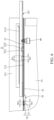
- FIG. 2 is another perspective view of the server rack, the servers and the network switches in FIG. 1 ;
Landscapes
- Engineering & Computer Science (AREA)
- Microelectronics & Electronic Packaging (AREA)
- General Engineering & Computer Science (AREA)
- Computer Hardware Design (AREA)
- Physics & Mathematics (AREA)
- Theoretical Computer Science (AREA)
- Thermal Sciences (AREA)
- Human Computer Interaction (AREA)
- General Physics & Mathematics (AREA)
- Cooling Or The Like Of Electrical Apparatus (AREA)
Abstract
Description
Claims (8)
Applications Claiming Priority (2)
| Application Number | Priority Date | Filing Date | Title |
|---|---|---|---|
| CN202110231857.4 | 2021-03-02 | ||
| CN202110231857.4A CN112987885B (en) | 2021-03-02 | 2021-03-02 | Server cabinet |
Publications (2)
| Publication Number | Publication Date |
|---|---|
| US20220287199A1 US20220287199A1 (en) | 2022-09-08 |
| US11765853B2 true US11765853B2 (en) | 2023-09-19 |
Family
ID=76352180
Family Applications (1)
| Application Number | Title | Priority Date | Filing Date |
|---|---|---|---|
| US17/346,689 Active 2042-02-25 US11765853B2 (en) | 2021-03-02 | 2021-06-14 | Server rack |
Country Status (2)
| Country | Link |
|---|---|
| US (1) | US11765853B2 (en) |
| CN (1) | CN112987885B (en) |
Families Citing this family (1)
| Publication number | Priority date | Publication date | Assignee | Title |
|---|---|---|---|---|
| CN115767978B (en) * | 2022-11-08 | 2024-12-17 | 超聚变数字技术有限公司 | Server support, server node and computing device |
Citations (16)
| Publication number | Priority date | Publication date | Assignee | Title |
|---|---|---|---|---|
| US20030161114A1 (en) * | 2001-06-29 | 2003-08-28 | Intel Corporation | Rack-mounted server and associated methods |
| US20030193781A1 (en) * | 2002-04-10 | 2003-10-16 | Mori Robert F. | System structure for convenient service access in a rack/cabinet |
| US6719149B2 (en) * | 2001-09-04 | 2004-04-13 | Allied Telesis Kabushiki Kaisha | Accommodation apparatus for communication devices |
| US20080217497A1 (en) * | 2007-03-09 | 2008-09-11 | Hon Hai Precision Industry Co., Ltd. | Server rack |
| US7508660B2 (en) * | 2006-06-07 | 2009-03-24 | Inventec Corporation | Fixing mechanism |
| US7780254B2 (en) * | 2008-10-09 | 2010-08-24 | Inventec Corporation | Slide rail structure |
| US8226181B2 (en) * | 2008-08-08 | 2012-07-24 | Inventec Corporation | Slide rail structure |
| US8287059B2 (en) * | 2009-11-04 | 2012-10-16 | Inventec Corporation | Rail device and server |
| US8371542B2 (en) * | 2010-09-13 | 2013-02-12 | Hong Fu Jin Precision Industry (Shenzhen) Co., Ltd. | Slide rail assembly |
| US8474924B2 (en) * | 2009-11-03 | 2013-07-02 | Inventec Corporation | Rail device and server |
| TW201703031A (en) * | 2015-07-14 | 2017-01-16 | 緯創資通股份有限公司 | Server kit capable of supporting hard disks, server slide rail applied to server kit, and related server system |
| US9648771B1 (en) * | 2016-03-31 | 2017-05-09 | Middle Atlantic Products, Inc. | Multi-piece rack shelf |
| US10111354B2 (en) * | 2015-01-27 | 2018-10-23 | Chenbro Micom Co., Ltd. | Storage carrier |
| US20200187378A1 (en) * | 2018-12-07 | 2020-06-11 | Chenbro Micom Co.,Ltd. | Server chassis |
| TWI711359B (en) * | 2020-01-15 | 2020-11-21 | 緯創資通股份有限公司 | Detachable partition assembly and chassis |
| RU2763157C2 (en) * | 2020-02-14 | 2021-12-27 | Общество С Ограниченной Ответственностью «Яндекс» | Frame structure |
Family Cites Families (9)
| Publication number | Priority date | Publication date | Assignee | Title |
|---|---|---|---|---|
| CN2585532Y (en) * | 2002-10-16 | 2003-11-05 | 川湖工厂股份有限公司 | Adjustable fixed structure of cable management frame |
| CN201707620U (en) * | 2010-04-16 | 2011-01-12 | 长盛科技股份有限公司 | Cloud server case |
| CN103163990B (en) * | 2011-12-16 | 2016-07-06 | 国家电网公司 | Cabinet-type server system |
| CN104298324A (en) * | 2014-09-25 | 2015-01-21 | 英业达科技有限公司 | Server |
| CN106292913B (en) * | 2016-08-05 | 2019-03-26 | 英业达科技有限公司 | server |
| CN109445536A (en) * | 2018-10-31 | 2019-03-08 | 英业达科技有限公司 | Fan bracket |
| CN110554748A (en) * | 2019-09-05 | 2019-12-10 | 英业达科技有限公司 | Server |
| CN210986568U (en) * | 2019-10-31 | 2020-07-10 | 北京比特大陆科技有限公司 | PCB heat dissipation assembly and server with same |
| CN111596737B (en) * | 2020-05-28 | 2023-09-19 | 英业达科技有限公司 | Servo chassis and cable management rack |
-
2021
- 2021-03-02 CN CN202110231857.4A patent/CN112987885B/en active Active
- 2021-06-14 US US17/346,689 patent/US11765853B2/en active Active
Patent Citations (19)
| Publication number | Priority date | Publication date | Assignee | Title |
|---|---|---|---|---|
| US20030161114A1 (en) * | 2001-06-29 | 2003-08-28 | Intel Corporation | Rack-mounted server and associated methods |
| US6719149B2 (en) * | 2001-09-04 | 2004-04-13 | Allied Telesis Kabushiki Kaisha | Accommodation apparatus for communication devices |
| US20030193781A1 (en) * | 2002-04-10 | 2003-10-16 | Mori Robert F. | System structure for convenient service access in a rack/cabinet |
| US7508660B2 (en) * | 2006-06-07 | 2009-03-24 | Inventec Corporation | Fixing mechanism |
| US20080217497A1 (en) * | 2007-03-09 | 2008-09-11 | Hon Hai Precision Industry Co., Ltd. | Server rack |
| US8226181B2 (en) * | 2008-08-08 | 2012-07-24 | Inventec Corporation | Slide rail structure |
| US7780254B2 (en) * | 2008-10-09 | 2010-08-24 | Inventec Corporation | Slide rail structure |
| US8474924B2 (en) * | 2009-11-03 | 2013-07-02 | Inventec Corporation | Rail device and server |
| US8287059B2 (en) * | 2009-11-04 | 2012-10-16 | Inventec Corporation | Rail device and server |
| US8371542B2 (en) * | 2010-09-13 | 2013-02-12 | Hong Fu Jin Precision Industry (Shenzhen) Co., Ltd. | Slide rail assembly |
| US10111354B2 (en) * | 2015-01-27 | 2018-10-23 | Chenbro Micom Co., Ltd. | Storage carrier |
| TW201703031A (en) * | 2015-07-14 | 2017-01-16 | 緯創資通股份有限公司 | Server kit capable of supporting hard disks, server slide rail applied to server kit, and related server system |
| US9648771B1 (en) * | 2016-03-31 | 2017-05-09 | Middle Atlantic Products, Inc. | Multi-piece rack shelf |
| US20200187378A1 (en) * | 2018-12-07 | 2020-06-11 | Chenbro Micom Co.,Ltd. | Server chassis |
| US11116104B2 (en) * | 2018-12-07 | 2021-09-07 | Chenbro Micom Co., Ltd. | Server chassis |
| US20210400834A1 (en) * | 2018-12-07 | 2021-12-23 | Chenbro Micom Co.,Ltd. | Server chassis |
| US11547013B2 (en) * | 2018-12-07 | 2023-01-03 | Chenbro Micom Co., Ltd. | Server chassis |
| TWI711359B (en) * | 2020-01-15 | 2020-11-21 | 緯創資通股份有限公司 | Detachable partition assembly and chassis |
| RU2763157C2 (en) * | 2020-02-14 | 2021-12-27 | Общество С Ограниченной Ответственностью «Яндекс» | Frame structure |
Also Published As
| Publication number | Publication date |
|---|---|
| CN112987885A (en) | 2021-06-18 |
| CN112987885B (en) | 2023-03-14 |
| US20220287199A1 (en) | 2022-09-08 |
Similar Documents
| Publication | Publication Date | Title |
|---|---|---|
| US6516954B2 (en) | Equipment rack with integral HVAC and power distribution features | |
| US8355246B2 (en) | Modular air management devices | |
| US9071041B2 (en) | Twist-in latching arrangement for cable management structure | |
| US5626406A (en) | Integrated chassis slide assembly | |
| US5957556A (en) | Cable management system for a computer | |
| US20120049706A1 (en) | Air Flow Management Enclosure | |
| US20050221683A1 (en) | Vertical cable manager | |
| US20110175505A1 (en) | Adjustable blanking panel | |
| US10701830B1 (en) | Data center cooling device | |
| US10707664B2 (en) | Enclosure and face plate support member for use with the enclosure | |
| US7229050B2 (en) | Raceway system | |
| CN113016240A (en) | Modular rack assembly | |
| US20200068747A1 (en) | Flue device for computer racks | |
| US10732680B1 (en) | Hard disk drive chassis and hard disk drive chassis assembly | |
| US20120273627A1 (en) | Horizontal Cable Manager | |
| US20130161277A1 (en) | Plenum Kit | |
| US11765853B2 (en) | Server rack | |
| CN104684354A (en) | Universal inlet duct system for side air intake equipment | |
| US8199486B2 (en) | Server cabinet | |
| US20090026326A1 (en) | Cable management apparatus for fans | |
| US8757581B2 (en) | Fixing device for fan | |
| US9485890B2 (en) | Electrical connector system | |
| US9297496B2 (en) | Plug-in module bottom rail system and method | |
| US20170234573A1 (en) | Baffle for directing air flow in a rack | |
| US20210345505A1 (en) | Systems and methods for modular cabinet cable pass-through |
Legal Events
| Date | Code | Title | Description |
|---|---|---|---|
| AS | Assignment |
Owner name: INVENTEC CORPORATION, TAIWAN Free format text: ASSIGNMENT OF ASSIGNORS INTEREST;ASSIGNOR:LU, XIAOGANG;REEL/FRAME:056587/0353 Effective date: 20210609 Owner name: INVENTEC (PUDONG) TECHNOLOGY CORPORATION, CHINA Free format text: ASSIGNMENT OF ASSIGNORS INTEREST;ASSIGNOR:LU, XIAOGANG;REEL/FRAME:056587/0353 Effective date: 20210609 |
|
| FEPP | Fee payment procedure |
Free format text: ENTITY STATUS SET TO UNDISCOUNTED (ORIGINAL EVENT CODE: BIG.); ENTITY STATUS OF PATENT OWNER: LARGE ENTITY |
|
| STPP | Information on status: patent application and granting procedure in general |
Free format text: DOCKETED NEW CASE - READY FOR EXAMINATION |
|
| STPP | Information on status: patent application and granting procedure in general |
Free format text: NON FINAL ACTION MAILED |
|
| STPP | Information on status: patent application and granting procedure in general |
Free format text: PUBLICATIONS -- ISSUE FEE PAYMENT VERIFIED |
|
| STCF | Information on status: patent grant |
Free format text: PATENTED CASE |